JP2004106974A - Conveying device for goods - Google Patents
Conveying device for goods Download PDFInfo
- Publication number
- JP2004106974A JP2004106974A JP2002269800A JP2002269800A JP2004106974A JP 2004106974 A JP2004106974 A JP 2004106974A JP 2002269800 A JP2002269800 A JP 2002269800A JP 2002269800 A JP2002269800 A JP 2002269800A JP 2004106974 A JP2004106974 A JP 2004106974A
- Authority
- JP
- Japan
- Prior art keywords
- guide
- group
- lane
- shift
- magnetic
- Prior art date
- Legal status (The legal status is an assumption and is not a legal conclusion. Google has not performed a legal analysis and makes no representation as to the accuracy of the status listed.)
- Granted
Links
- 238000011144 upstream manufacturing Methods 0.000 claims abstract description 54
- 230000032258 transport Effects 0.000 claims description 46
- 238000000034 method Methods 0.000 abstract description 7
- 230000008569 process Effects 0.000 abstract description 6
- 230000008859 change Effects 0.000 abstract description 3
- 238000004519 manufacturing process Methods 0.000 description 15
- 230000003028 elevating effect Effects 0.000 description 4
- 238000010438 heat treatment Methods 0.000 description 3
- 238000010586 diagram Methods 0.000 description 2
- XAGFODPZIPBFFR-UHFFFAOYSA-N aluminium Chemical compound [Al] XAGFODPZIPBFFR-UHFFFAOYSA-N 0.000 description 1
- 229910052782 aluminium Inorganic materials 0.000 description 1
- 230000000694 effects Effects 0.000 description 1
- 230000002452 interceptive effect Effects 0.000 description 1
- 238000010409 ironing Methods 0.000 description 1
- 239000000696 magnetic material Substances 0.000 description 1
- 239000000463 material Substances 0.000 description 1
- 230000007246 mechanism Effects 0.000 description 1
- 229920003023 plastic Polymers 0.000 description 1
- 239000004033 plastic Substances 0.000 description 1
- 238000003825 pressing Methods 0.000 description 1
- 238000007634 remodeling Methods 0.000 description 1
- 239000004575 stone Substances 0.000 description 1
Images


Landscapes
- Branching, Merging, And Special Transfer Between Conveyors (AREA)
- Attitude Control For Articles On Conveyors (AREA)
- Relays Between Conveyors (AREA)
Abstract
Description
【0001】
【発明の属する技術分野】
本発明は、たとえば異なる形状,寸法の缶等を同一製造ラインで製造する多品種生産方式の製造ラインに適した物品の搬送装置に関し、特に予備の処理設備の切換ラインを備えた物品の搬送装置に関する。
【0002】
【従来の技術】
従来より、缶製造ラインの生産性を上げるため、複数の処理機械、例えば複数のプレスを並列に配置し、缶を同時並行で成形して同一の搬送ラインを通じて次工程に搬送することがなされている。
従来の缶の生産は、一種類の形状,寸法の缶を大量に生産する一品種大量生産方式が主流であったが、近年、様々な形状,寸法の缶を必要数だけ生産する多品種生産方式に変わりつつある。
従来の大量生産方式の製造ラインで多品種の缶を生産するためには、プレスの型替え作業の間、製造ラインを止めるか、異なる形状,寸法の缶毎に新たに製造ラインを構築する等の対応が必要で、生産性が悪くなる。
【0003】
【発明が解決しようとする課題】
そこで、このような生産性低下を防止するためには、異なる形状,寸法の缶の製造に際し、予備の処理設備、例えばプレスを準備しておいて、型替え作業中は予備のプレスを稼動することが考えられるが、缶の搬送ラインが複雑となり、搬送系をどのような配置にするかが重要な問題となる。
【0004】
本発明は上記した従来の問題を解決するためになされたもので、型替え等の作業中にも予備の処理設備に切換えて物品の処理を行い得る搬送レーンの切換構造を構築し、多品種の物品を効率よく処理し得る物品の搬送装置を提供することにある。
【0005】
【課題を解決するための手段】
上記目的を達成するために、本発明にあっては、互いに隣り合う2つのレーンを備えた主コンベアと、該主コンベアの側方に配設された3つの処理設備とを備え、該3つの処理設備のうち一つを予備として2つの処理設備で処理された物品群を主コンベアの側方から2つのレーンに供給して搬送する物品の搬送装置であって、
前記2つのレーンのうち第1のレーンから第2のレーンに物品群を移動させるシフトガイドと、前記3つの処理設備のうち第1の処理設備から供給される物品群を前記シフトガイドより下流位置で第1のレーンに流入させる下流側ガイドと、前記3つの処理設備のうち第2の処理設備から供給される物品群を前記シフトガイドより上流位置で前記第1のレーンに流入させる中間ガイドと、前記3つの処理設備のうち第3の処理設備から供給される物品群を前記シフトガイドより上流位置で第2のレーンに流入させる上流側ガイドとを備え、前記シフトガイドのシフト機能の有効無効を切換可能としたことを特徴とする。
【0006】
下流側ガイドについてもガイド機能の有効無効を切換可能としたことを特徴とする。
前記第1,第2および第3の処理設備が、主コンベアの搬送方向に沿って互いに隣り合って配設されていることを特徴とする。
主コンベア上の各レーンを搬送される各物品群の物品の幅方向の位置関係は、前記第1,第2,第3の各処理設備から主コンベアに供給される際の物品の幅方向の位置関係に対応する構成となっている。
【0007】
前記シフトガイド,下流側ガイド,中間ガイドおよび上流側ガイドは、磁力によって物品群を移動させる構成となっていることを特徴とする。
前記シフトガイドのシフト機能の有効無効の切換は、前記シフトガイドを物品群の搬送に磁力が影響しない位置まで退避させる退避手段によって行う。
下流側ガイドのガイド機能の有効無効の切換は、前記上流側ガイドを物品群の搬送に影響しない位置まで退避させる退避手段によって行う。
【0008】
前記シフトガイド,上流側ガイド,中間ガイドおよび下流側ガイドは、主コンベアの下方に配置される磁石軌道によって構成される。磁石軌道とは、予定される物品の軌道に沿って磁石を配置した構造である。
前記シフトガイド,上流側ガイド,中間ガイドおよび下流側ガイドは、主コンベアの上方に配置される磁石軌道によって構成してもよい。
前記磁石軌道は複数本のマグネットレールによって構成される。隣り合うマグネットレールの対向面の磁極は同極となっていることが好ましい。
第1乃至第3の処理設備は缶を絞り加工するプレス設備に適用することが好適である。なお、ここでの絞り加工とは、絞り加工,薄肉化絞り加工,しごき加工,これらの組み合わせ加工等を含むものである。
【0009】
【発明の実施の形態】
以下に本発明を図示の実施の形態に基づいて説明する。
実施の形態1
図1乃至図4は、本発明の実施の形態1に係る物品の搬送装置を示している。
この物品の搬送装置1は、2種類の缶を同一ラインで製造する多品種生産方式の缶の製造ラインに適用されるもので、互いに隣り合う2つの第1,第2レーン11,12を有する主コンベア10と、主コンベア10の側方に主コンベア10の搬送方向(図中矢印F)に沿って配設される互いに隣り合う処理設備としての3台の第1,第2,第3プレス21,22,23と、各プレス21,22,23で成形処理された第1,第2,第3缶群C1,C2,C3をそれぞれ主コンベア10に側方から供給する第1,第2,第3供給コンベア41,42,43とを備えている。
【0010】
主コンベア10の第1レーン11の上流端は第2プレス22との対向位置までで、第1レーン11には第1プレス21と第2プレス22が対向する。第2レーン12の上流端は第1レーン11よりも第3プレス23との対向位置まで上流側に延びており、第3プレス23からの第3供給コンベア43は第2レーン12の側縁に直接接続されている。
主コンベア10は、第1,第2レーン11,12に対応して互いに同期回転する長さの異なる2本の無端状のベルト11a,12aと、ベルト11a,12aを回転駆動するモータ15とを備えている。ベルト11a,12aはプラスチックス等の非磁性材料によって構成されている。ベルト11a,12aはフレーム17に配置された複数のスプロケット16,16間に掛け回されている。ベルト11a,12aはスプロケット16が噛み合うチェーン構成となっており、一つのスプロケット16がモータによって回転駆動される。フレーム17は支持脚18によって所定高さに支持されている。
【0011】
第1,第2,第3プレス21,22,23は缶を板材から絞り加工するもので、各缶の形状,寸法に応じた金型が装着され、形状,寸法の異なる缶が成形可能である。次工程設備はプレスされた缶を加熱するオーブン等の熱処理設備30であり、特に形状,寸法に関係しない。
第1,第2,第3供給コンベア41,42,43は、いずれも主コンベア10に対して互いに直交する配置で、主コンベア10側縁から直角に各缶群C1,C2,C3が乗り移る。この例では、第1,第2供給コンベア41,42は主コンベア10の第1レーン11の側縁に接続され、第3供給コンベア43は第2レーン12の側縁に接続されている。第1,第2,第3供給コンベア41,42,43は、共に多数の缶Cを複数列に整列させて搬送する多列構成で、図示例では、すべて6列で搬送される。主コンベア10の第1レーン11及び第2レーン12もそれぞれ6列で搬送される。
【0012】
主コンベア10には、互いに隣り合う第1,第2レーン11,12のうちプレス側の第1レーン11から反プレス側の第2レーン12に缶群を磁力によって移動させるシフトガイドとしての磁気シフトガイド51が設けられている。この磁気シフトガイド51より下流位置には、下流側の第1プレス21から供給される第1缶群C1を磁力によって第1レーン11に流入させる下流側ガイドとしての第1磁気ガイド61が設けられている。
【0013】
磁気シフトガイド51より上流位置には、中間の第2プレス22から供給される第2缶群C2を磁力によって第1レーン11に流入させる中間ガイドとしての第2磁気ガイド62が、さらに、磁気シフトガイド51より上流位置には前記第2プレス22よりさらに一つ上流側の第3プレス23から供給される第3缶群C3を磁力によって第2レーン12に流入させる上流側ガイドとしての第3磁気ガイド63が設けられている。
【0014】
磁気シフトガイド51は、シフト機能の有効無効が切換可能となっており、この実施の形態では、磁気シフトガイド51を缶群の搬送に磁力が影響しない位置まで退避させる退避装置70によって行う。磁気シフトガイド51を退避させれば、第2缶群C2は第2レーン12にシフトせず、第1レーン11上を搬送される。
退避装置70は、磁気シフトガイド51の前端部及び後端部の左右両端を支持する4つの昇降装置71によって構成され、昇降装置71によって磁気シフトガイド51の高さを調整し、主コンベア10上の缶群に対する距離を調整するようになっている。昇降装置71としては、油空圧シリンダやねじ機構など、種々の構成を適用可能である。
【0015】
また、第1磁気ガイド61も、ガイド機能の有効無効を切換可能となっており、この実施の形態では、磁気シフトガイド51と同様に、缶群の搬送に磁力が影響しない位置まで退避させる退避装置70によって行われる。第1磁気ガイド61を退避させれば、第2缶群C2が第1磁気ガイド61に乱されることなく、缶列を維持しつつ整然と搬送される。
【0016】
退避装置70は、第1磁気ガイド61の前端部及び後端部の左右両端を4つの昇降装置71によって支持し、昇降装置71の調整によって第1磁気ガイド61の高さを調整し、主コンベア10上の缶群に対する距離を調整するようになっている。
【0017】
磁気シフトガイド51は、図3に示すように、缶を案内する複数の軌道に沿って配置される複数本(この実施の形態では6本)のマグネットレール501によって構成される磁石軌道50を備え、主コンベア10の第1,第2レーン11,12の各ベルト11a,12aの下方に配置されている。
【0018】
各マグネットレール501は互いに平行に配置されるもので、第1レーン11を第2レーン12の境界を跨いで搬送方向に対して斜めに延びる斜行レール部501aと、この斜行レール部101aの上流端から上流に向かって搬送方向に沿って真っ直ぐ延びる第1直行レール部501bと、斜行レール部501aの下流端から下流に向かって搬送方向に沿って真っ直ぐ延びる第2直行レール部501cと、を備えた構成となっている。斜行レール部501aは搬送方向下流に向かうにしたがって徐々に反プレス側に変位するように傾斜している。第1直行レール部501bの長さは、反プレス側のマグネットレール501がプレス側のマグネットレール501より短く、各上流端位置が搬送方向に同一位置となるように揃えられている。また、第2直行レール部501cの長さは、反プレス側のマグネットレール501がプレス側のマグネットレール501より長く、各下流端位置が搬送方向同一位置となるように揃えられている。
この6本のマグネットレール501によって、缶列が第1レーン11上での並び順を維持したままで、第2レーン12上にシフトされる。
【0019】
各マグネットレール501は、ベースプレート50aと、ベースプレート50a上に重ねられる磁石50bと、磁石50b上面を覆い磁石50bをベースプレート50aに対して固定する薄肉の磁石カバー50cと、を備えた構成となっている。ベースプレート50aと磁石50bは同一幅で、ベースプレート50aの下面には取付用のねじ穴50dが設けられ、組み付けフレーム50eにねじ部材50fによって一対的に固定され、組み付けフレーム50eが前記退避装置70によって支持される。
【0020】
磁石カバー50cは磁力作用面となる磁石上面を覆う上面部50c1と、上面部50c1の左右側縁から下方に屈曲して磁石側面を支持すると共に下端部がベースプレート50aの左右側面にねじ部材50gによって固定される側面部50c2とから構成されている。
また、各マグネットレール501は、それぞれ中心線に対して左右両側部がS極,N極となっており、隣り合うマグネットレールの対向部分は同極となっている。
【0021】
次に、第1缶群C1を案内する第1磁気ガイド61と、第2缶群C2を案内する第2磁気ガイド62と、第3缶群C3を案内する第3磁気ガイド63について説明する。
これらの第1乃至第3磁気ガイド61〜63は基本的に同一の構成で、図4に示すような磁石軌道60によって構成される。
磁石軌道60は缶群の軌道に沿って磁石を配置したもので、缶を案内する複数の軌道に沿って互いに平行に配置される複数本(図示例では6本)のマグネットレール601によって構成され、主コンベア10の第1,第2レーン11,12の各ベルト11a,12aの下方に配置される。
【0022】
各マグネットレール601の形状は「く」の字形状で、主コンベア10のプレス側の側縁から反プレス側に離れるに従って徐々に搬送方向下流に向かって斜めに延びる斜行レール部601aと、この斜行レール部601aの搬送方向下流端から主コンベア10の搬送方向に沿ってさらに下流側に延びる直行レール部601bと、を備えている。
この平行に配置される6本のマグネットレール601によって、供給コンベア41,42,43上の缶列C1,C2,C3の並び順が主コンベア10の第1レーン11あるいは第2レーン12上でも対応する並び順となるように案内される。
【0023】
各マグネットレール601の断面構造は上記磁気シフトガイド51を構成するマグネットレール501と全く同一の構成で、各マグネットレール601は、ベースプレート60aと、ベースプレート60a上に重ねられる磁石60bと、磁石60b上面を覆い磁石60bをベースプレート60aに対して固定する薄肉の磁石カバー60cと、を備えた構成となっている。ベースプレート60aと磁石60bは同一幅で、ベースプレート60aの下面には取付用のねじ穴60dが設けられ、組み付けフレーム60eにねじ部材60fによって一対的に固定され、組み付けフレーム60eが前記退避装置70によって支持される。
【0024】
磁石カバー60cは磁力作用面となる磁石上面を覆う上面部60c1と、上面部60c1の左右側縁から下方に屈曲して磁石側面を支持すると共に下端部がベースプレート60aの左右側面にねじ部材60gによって固定される側面部60c2とから構成されている。
また、各マグネットレール601は、それぞれ中心線に対して左右両側部がS極,N極となっており、隣り合うマグネットレールの対向部分は同極となっている。
主コンベア10のプレス側側縁から主コンベア10上に乗り移った缶Cは、案内用磁石軌道60の各マグネットレール601の斜行レール部60aによって互いに干渉することなく、第1レーン11あるいは第2レーン12上の6列の軌道に案内される。
なお、上記した磁気シフトガイド51のマグネットレール501および第1〜第3磁気ガイド61〜63のマグネットレール601の各斜行レール部501a,601aは直線的に構成しているが、円弧形状など曲線構成としてもよい。
【0025】
次に、図2を参照して、本実施の形態の物品の搬送装置による缶の搬送について説明する。
缶の搬送は、予備となるプレスによって3形態がある。
1)第3プレス23を予備とする場合
この場合には、図2(A)に示すように、第3プレス23からの第3缶群C3が第2レーン12上を搬送されないので、磁気シフトガイド51および第1磁気ガイド61は初期状態のままとする。
第1プレス21から第1磁気ガイド61を通じて第1缶群C1が主コンベア10上の第1レーン11上を搬送され、第2プレス22から第2磁気ガイド62を通じて第1レーン11に案内された第2缶群C2は、磁気シフトガイド51の各マグネットレール501に磁気吸引され、各マグネットレール501に沿って第2レーン12に移動し、第2レーン12上を搬送される。
【0026】
2)第2プレス22を予備とする場合
次に、第2プレス22の金型を交換する場合には、図2(B)に示すように、第2プレス22が稼動状態の間に第3プレス23の稼動準備をし、第2プレス22を停止すると共に第3プレス23を稼動し、製造ラインを停止することなく第2プレス22の金型交換作業を行う。この場合、磁気シフトガイド51を退避させてシフト機能を無効とする。
第3プレス23から供給される第3缶群C3は第2レーン12上を搬送され、磁気シフトガイド51が退避されているので、第3缶群C3が磁気シフトガイド51上を通過しても第3缶群C3の缶列が乱されない。第1レーン11には第1プレス21から供給される第1缶群C1が第1レーン11上を搬送される。
【0027】
3)第1プレス21を予備とする場合、
この場合にも、図2(C)に示すように、磁気シフトガイド51を退避させてシフト機能を無効とすると同時に、第1磁気ガイド61を退避させてガイド機能を無効とする。
第2プレス22から第2磁気ガイド62を通じて案内された第2缶群C2は第1レーン11上を搬送される。第2缶群C2が第1磁気ガイド61上を通過しても、第1磁気ガイド61が退避されているので、第2缶群C2の缶列が乱されない。
また、第3プレス23から供給される第3缶群C3は第2レーン12を搬送される。磁気シフトガイド51が退避されているので、第3缶群C3が磁気シフトガイド51上を通過しても缶列を乱されることなく、第2レーン12上を搬送される。
【0028】
他の実施の形態
次に本発明の他の実施の形態について説明する。以下の説明では上記実施の形態と異なる点についてのみ説明し、同一の構成部分については同一の符号を付して説明を省略するものとする。
【0029】
実施の形態2
図5には、本発明の実施の形態2に係る物品の搬送装置を示している。
上記実施の形態では、隣り合う第1,第2,第3プレス21,22,23のうち一つを予備とし残り二つのプレスから第1,第2レーン11,12に缶群を供給する搬送構成を一組だけ有する構成であったが、この実施の形態2では、このような3つのプレスから2つのレーンに供給される缶群の搬送構成を複数組有する場合で、下流側の組の上流側2つのプレスと上流側の組の下流側2つのプレスが重複し、下流側の組の反プレス側のレーンと上流側の組のプレス側のレーンが重複する構成となっている。
図示例では本発明の搬送構成を2組有する場合で、全体として4つのプレスのうち一つを予備とし、3つのプレスで成形された缶群を3つのレーンに案内して搬送させるようになっている。
第1の組の搬送構成は、隣り合う第1,第2,第3プレス21,22,23から供給される缶群を第1,第2レーン11,12に搬送する搬送構成、第2の組の搬送構成は、隣り合う第2,第3,第4プレス22,23,24から第2,第3レーン12,13に搬送する搬送構成となっている。
【0030】
第1の組の搬送構成は、第1レーン11から反プレス側の第2レーン12に物品群を磁力によって移動させる第1磁気シフトガイド51と、第1磁気シフトガイド51より下流位置で第1のプレス21から供給される第1缶群C1を磁力によって第1レーン11に流入させる下流側ガイドとしての第1磁気ガイド61と、磁気シフトガイド51より上流位置で第2プレス22から供給される第2缶群C2を磁力によって第1レーン11に流入させる中間ガイドとしての第2磁気ガイド62と、磁気シフトガイド51の上流位置で第3プレス23から供給される第3缶群C3を磁力によって第2レーン12に流入させる上流側ガイドとしての第3磁気ガイド63とを備えている。
【0031】
この場合、第2レーン12の第1磁気シフトガイド51上流側には、第2磁気シフトガイド52と第2の磁気ガイド62、第3の磁気ガイド63が存在するが、中間の第2プレス22からの第2物品群C2を第2レーンに流入させるガイドは第1磁気シフトガイド51であり、第2磁気ガイド62が本発明の中間ガイド、第3磁気ガイド63が上流側ガイドに対応する。
第1シフトガイド51のシフト機能の有効無効を退避装置70によって切換可能とし、第1磁気ガイド61のガイド機能の有効無効を退避装置70によって切換可能とする。
【0032】
次に、第2の組の搬送構成は、第2レーン12から反プレス側の第3レーン13に缶群を磁力によって移動させる第2磁気シフトガイド52と、第2磁気シフトガイド52より下流位置で下流側の第2のプレス22から供給される第2缶群C2を磁力によって第2レーン12に流入させる下流側ガイドとしての第1シフトガイド51と、第2磁気シフトガイド52より上流位置で中間の第3プレス23から供給される第3缶群C3を磁力によって第2レーン12に流入させる中間ガイドとしての第3磁気ガイド63と、上流側の第4プレス24から供給される第4缶群C4を第2シフトガイド52より上流位置で磁力によって第3レーン13に流入させる上流側ガイドとしての第4磁気ガイド64とを備えている。
【0033】
この場合、第2,第3レーン12,13の関係では、第1磁気シフトガイド51が、プレス側のレーンとなる第2レーン12に下流側の第2プレス22からの第2缶群C2を流入させる下流側ガイドに対応する。
そして、第2磁気シフトガイド52のシフト機能の有効無効を退避装置70によって切換可能とし、下流側ガイドとしての第1シフトガイド51のガイド機能についても退避装置70によって切換可能となっている。
【0034】
本実施の形態2では、つぎの4つの搬送形態がある。
1)第4プレス24を予備とする場合
この場合には、第1,第2磁気シフトガイド51,52、第1磁気ガイド61は退避させないで、シフト機能およびガイド機能を有効としておく。
第1レーン11には第1缶群C1が搬送され、第2レーンには第2缶群C2が搬送され、第3レーン13には第3缶群C3が搬送される。
2)第3プレス23を予備とする場合
この場合には、第2磁気シフトガイド52を退避させてシフト機能を無効とする。
第1レーン11には第1缶群C1が、第2レーン12には第2缶群C2が、第3レーン13には第4缶群C4が搬送される。
【0035】
3)第2プレス22を予備とする場合
この場合には、第1,第2磁気シフトガイド51,52を退避させてシフト機能を無効とする。
第1レーン11には第1缶群C1が、第2レーン12には第3缶群C3が、第3レーン13には第4缶群C4が搬送される。
4)第1プレス21を予備とする場合、
この場合には、第1,第2磁気シフトガイド51,52および第1磁気ガイド61を退避させて、シフト機能およびガイド機能を無効とする。
第1レーン11には第2缶群C2が、第2レーン12には第3缶群C3が、第3レーン13には第4缶群C4が搬送される。
【0036】
実施の形態3
図6には、本発明の本実施の形態3に係る物品の搬送装置を示している。
この実施の形態3は、3つのプレスから2つのレーンに供給される缶群の搬送構成を複数組有する場合で、各組の搬送構成は下流側の組の上流側2つのプレスと上流側の組の下流側2つのプレスが重複し、下流側の組の2つのレーンと上流側の組の2つのレーンが共通する構成となっている。
【0037】
図示例では搬送構成を2組有する場合で、全体として4つのプレスの内2つのプレスを予備とするようになっており、第1組の搬送構成は、隣り合う第1,第2,第3プレス21,22,23から第1,第2レーン11,12に供給される缶群を第1,第2レーン11,12に搬送する搬送構成、第2組の搬送構成は、隣り合う第2,第3,第4プレスから第1,第2レーン11,12に搬送する搬送構成となっている。
第1組の搬送構成は、第1レーン11から反プレス側の第2レーン12に物品群を磁力によって移動させる第1磁気シフトガイド51と、第1磁気シフトガイド51より下流位置で第1のプレス21から供給される第1缶群C1を磁力によって第1レーン11に流入させる下流側ガイドとしての第1磁気ガイド61と、磁気シフトガイド51より上流位置で第2プレス22から供給される第2缶群C2を磁力によって第1レーン11に流入させる中間ガイドとしての第2磁気ガイド62と、磁気シフトガイド51の上流位置で第3プレス23から供給される第3缶群C3を磁力によって第2レーン12に流入させる上流側ガイドとしての第2磁気シフトガイド52とを備えている。
第1磁気シフトガイド51のシフト機能の有効無効を退避装置70によって切換可能とし、第1磁気ガイド61のガイド機能の有効無効を退避装置70によって切換可能とする。
【0038】
次に、隣り合う第2,第3,第4プレス22,23,24から第1,第2レーン11,12に供給される缶群の搬送構成について説明する。
第2の組の搬送構成は、第1レーン11から反プレス側の第2レーン12に物品群を磁力によって移動させる第2磁気シフトガイド52と、第2磁気シフトガイド52より下流位置で第2のプレス22から供給される第2缶群C1を磁力によって第1レーン11に流入させる下流側ガイドとしての第2磁気ガイド62と、第2磁気シフトガイド52より上流位置で第3プレス23から供給される第3缶群C3を磁力によって第1レーン11に流入させる中間ガイドとしての第3磁気ガイド63と、第2磁気シフトガイド52の上流位置で第4プレス24から供給される第4缶群C4を磁力によって第2レーン12に流入させる上流側ガイドとしての第4磁気ガイド64とを備えている。
第2磁気シフトガイド52のシフト機能の有効無効が退避装置70によって切換可能とし、第2磁気ガイド62のガイド機能の有効無効を退避装置70によって切換可能とする。
この場合にも、第1,第2磁気シフトガイド51,52および第1磁気ガイド61,第2磁気ガイド62を適宜退避させることにより、搬送経路を切り換えることが可能となる。
【0039】
なお、上記各実施の形態では、各プレスから供給される缶群の缶列と主コンベア上の缶列の列数を同数としているが、列数が異なっていてもよい。また、多数の缶が整列しないで不規則に搬送されるランダム搬送についても適用可能である。
また、処理設備としての各プレスを主コンベアの片側に搬送方向に沿って隣り合って配置される場合について説明したが、処理設備が主コンベアの両側に配置される場合についても適用可能であり、処理設備の配置構成は限定されない。
また、上記各実施の形態では、磁気シフトガイド、上流側,中間および下流側磁気ガイドの磁石軌道を永久磁石によって構成したが、電磁石によって構成してもよい。電磁石によって構成する場合には、磁気シフトガイドや上流側磁気ガイドのシフト機能およびガイド機能の有効,無効の切換は電気的に行うことができる。有効,無効の切換に退避装置を用いる場合には、上記各実施の形態では下方に退避させる構成としたが、側方に退避させる構成としてもよい。
また、上記各実施の形態では、磁石軌道を線状に延びるマグネットレールによって構成としたが、軌道に沿って点状の磁石を飛び石状に配置して軌道を構成してもよい。
さらに、磁石軌道は缶に磁力を作用させて所定方向に案内できればよく、主コンベア10の上方に配置してもよい。
また、上記各実施の形態では、シフトガイド,上流側,中間および下流側ガイドを磁力によって物品を移動させる構成としているが、磁力を用いないで、例えばバキュームを利用したり、ガイド板に当接させて物品群を案内するような案内構造としてもよく、アルミ缶のような物品の搬送についても適用可能である。
【0040】
【発明の効果】
以上説明したように、本請求項1に記載の発明によれば、第1のレーンから第2のレーンに物品群を移動させるシフトガイドと、第1の処理設備から供給される物品群を第1のレーンに流入させる下流側ガイドと、第2の処理設備から供給される物品群を第1のレーンに流入させる中間ガイドと、第3の処理設備から供給される物品群を第2のレーンに流入させる上流側ガイドとを備え、シフトガイドのシフト機能の有効無効を切換可能としたので、予備となる処理設備の位置に応じてシフトガイドのシフト機能の有効無効を切り換えることにより、一つの処理設備が型替え等の作業中であっても他の処理設備によって物品を処理して下流側の次工程の設備に搬送可能であり、多品種の物品を効率よく生産することができる。また、最新式の処理設備に更新した場合に、旧設備を予備として有効利用することができる。
請求項2に記載の発明によれば、下流側ガイドについても有効無効を切換可能としたので、第1の処理設備についても予備として使用することができる。
請求項3に記載の発明によれば、第1,第2および第3の処理設備が、主コンベアの搬送方向に沿って互いに隣り合って配置されているので、処理設備を主コンベアの片側に配置することができる。
請求項4に記載の発明によれば、主コンベア上の物品の幅方向の位置関係が各処理設備から主コンベアに供給される物品の幅方向の位置関係に対応する構成となっているので、物品同士が互いに干渉することなく、主コンベアへの乗り移りがスムースになる。
請求項5に記載の発明によれば、シフトガイド,下流側ガイド,中間ガイドおよび上流側ガイドは、磁力によって物品群を移動させる構成となっているので、物品を非接触で移動させることができる。
請求項6,7に記載の発明によれば、シフトガイド,上流側,中間および下流側ガイドの機能を無効にする手段は、物品群の搬送に磁力が影響しない位置まで退避させる構成としたので、簡単かつ確実に無効にすることができる。
【0041】
請求項8に記載の発明によれば、シフトガイド,上流側,中間および下流側ガイドは、主コンベアの下方に配置される磁石軌道によって構成されるので、構成が簡単で、また、物品を磁気吸引力でコンベアに対して吸引するので、搬送される物品が安定する。
また、請求項9に記載のように、磁石軌道を主コンベアの上方に配置すれば、物品の主コンベアに対する接触荷重が小さくなり、物品が移動させやすくなる。
【0042】
請求項10に記載の発明によれば、磁石軌道は複数本のマグネットレールによって構成されるので、物品はマグネットレールに沿って安定して移動する。
る。
【0043】
請求項11に記載の発明によれば、隣り合うマグネットレールの対向面の磁極は同極となっているので、物品が隣り合うマグネットレールにまたがることがなく、一つのマグネットレールに沿って案内される。
請求項12に記載のように、本発明を缶のプレス工程に適用すれば、金型の交換作業をラインを止めることなく行うことができ、生産性向上を図ることができる。
【図面の簡単な説明】
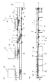
【図1】図1は本発明の実施の形態1に係る物品の搬送装置を示すもので、同図(A)は一部破断平面図、同図(B)は正面図である。
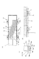
【図2】図2(A)乃至(C)は図1の装置の3つの各搬送形態を示す説明図である。
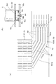
【図3】図3(A)は図1の装置の磁気シフトガイド部分の拡大平面図、同図(B)は同図(A)の正面図、同図(C)はマグネットレールの構造を示す断面図である。
【図4】図4(A)は図1の装置の第1磁気ガイドの部分拡大平面図、同図(B)は同図(A)のマグネットレールの構造を示す断面図である。
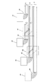
【図5】図5は本発明の実施の形態2に係る物品の搬送装置の搬送経路を模式的に示す図である。
【図6】図6は本発明の実施の形態3に係る物品の搬送装置の搬送経路を模式的に示す図である。
【符号の説明】
1 物品の搬送装置、10 主コンベア
11,12 第1,第2レーン
15 モータ、16 スプロケット、17 フレーム
C1,C2,C3 第1,第2,第3缶群
21,21,23 第1,第2,第3プレス(処理設備)
30 熱処理設備(次工程設備)
41,42,43 第1,第2,第3供給コンベア
51 磁気シフトガイド
50 磁石軌道
501 マグネットレール
501a 斜行レール部、501b,c 第1,第2直行レール部
50a ベースプレート、50b 磁石、
50c 磁石カバー、50c1 上面部、50c2 側面部
50d ねじ穴、50e 組み付けフレーム、50f,50g ねじ部材
61 第1磁気ガイド(下流側磁気ガイド)
62 第2磁気ガイド(中間磁気ガイド)
63 第3磁気ガイド(上流側磁気ガイド)
60 磁石軌道
601 マグネットレール、601a 斜行レール部、601b 直行レール部
70 退避装置、71 昇降装置[0001]
TECHNICAL FIELD OF THE INVENTION
BACKGROUND OF THE
[0002]
[Prior art]
Conventionally, in order to increase the productivity of a can manufacturing line, a plurality of processing machines, for example, a plurality of presses are arranged in parallel, and cans are formed simultaneously and transferred to the next step through the same transfer line. I have.
Conventional production of cans was based on a single-product mass-production system in which cans of a single shape and size were mass-produced. In recent years, multi-product production of the required number of cans of various shapes and sizes has been performed. The method is changing.
In order to produce many kinds of cans on a conventional mass production type production line, the production line must be stopped during the press change operation, or a new production line must be constructed for each can of different shape and size. Needs to be dealt with, resulting in poor productivity.
[0003]
[Problems to be solved by the invention]
Therefore, in order to prevent such a decrease in productivity, when manufacturing cans having different shapes and dimensions, a spare processing facility, for example, a press is prepared, and the spare press is operated during the mold changing operation. However, the transport line for cans becomes complicated, and how to arrange the transport system becomes an important issue.
[0004]
SUMMARY OF THE INVENTION The present invention has been made to solve the above-described conventional problems, and has established a transport lane switching structure capable of processing articles by switching to a spare processing facility even during work such as type change. It is an object of the present invention to provide an article conveying device capable of efficiently processing the same article.
[0005]
[Means for Solving the Problems]
In order to achieve the above object, according to the present invention, there is provided a main conveyor having two lanes adjacent to each other, and three processing facilities arranged on the sides of the main conveyor, and An article transport apparatus that supplies and transports a group of articles processed by two processing facilities from one side of a main conveyor to two lanes with one of the processing facilities as a spare,
A shift guide that moves a group of articles from a first lane to a second lane of the two lanes; and a group of articles supplied from the first processing facility among the three processing facilities is positioned downstream of the shift guide. And a middle guide for causing a group of articles supplied from a second processing facility among the three processing facilities to flow into the first lane at a position upstream of the shift guide. An upstream guide for causing a group of articles supplied from a third processing facility among the three processing facilities to flow into a second lane at a position upstream of the shift guide, and enabling or disabling a shift function of the shift guide. Can be switched.
[0006]
The present invention is also characterized in that the validity / invalidity of the guide function can be switched for the downstream side guide.
The first, second, and third processing facilities are arranged adjacent to each other along a conveying direction of a main conveyor.
The positional relationship in the width direction of the articles of each group of articles conveyed on each lane on the main conveyor is determined in the width direction of the articles when supplied to the main conveyor from the first, second, and third processing facilities. It has a configuration corresponding to the positional relationship.
[0007]
The shift guide, the downstream guide, the intermediate guide, and the upstream guide are configured to move an article group by magnetic force.
The switching of the shift function of the shift guide between valid and invalid is performed by a retracting unit that retracts the shift guide to a position where the magnetic force does not affect the conveyance of the group of articles.
The switching of the guide function of the downstream guide between valid and invalid is performed by a retracting unit that retracts the upstream guide to a position that does not affect the conveyance of the group of articles.
[0008]
The shift guide, the upstream guide, the intermediate guide, and the downstream guide are constituted by magnet tracks arranged below the main conveyor. The magnet track is a structure in which magnets are arranged along the track of a planned article.
The shift guide, the upstream guide, the intermediate guide, and the downstream guide may be constituted by magnet tracks arranged above the main conveyor.
The magnet track is constituted by a plurality of magnet rails. It is preferable that the magnetic poles on the opposing surfaces of the adjacent magnet rails have the same polarity.
The first to third processing facilities are preferably applied to a press facility for drawing a can. The drawing here includes drawing, thinning drawing, ironing, a combination thereof, and the like.
[0009]
BEST MODE FOR CARRYING OUT THE INVENTION
Hereinafter, the present invention will be described based on the illustrated embodiments.
1 to 4 show an article conveying apparatus according to
The
[0010]
The upstream end of the
The
[0011]
The first, second, and
The first, second, and
[0012]
The
[0013]
At a position upstream of the
[0014]
The shift function of the
The retracting
[0015]
The first
[0016]
The retracting
[0017]
As shown in FIG. 3, the
[0018]
The magnet rails 501 are arranged in parallel with each other, and include a
With these six
[0019]
Each
[0020]
The
In addition, each
[0021]
Next, the first
These first to third
The magnet track 60 has magnets arranged along the trajectory of the can group, and is constituted by a plurality of (six in the illustrated example) magnet rails 601 arranged parallel to each other along a plurality of trajectories for guiding the can. The first and
[0022]
Each of the magnet rails 601 has a “<” shape, and a
With the six
[0023]
The sectional structure of each
[0024]
The
In addition, each
The cans C transferred from the press-side edge of the
The sloping
[0025]
Next, with reference to FIG. 2, the transport of cans by the article transport device of the present embodiment will be described.
There are three types of can transport depending on the press used as a backup.
1) When the
In this case, as shown in FIG. 2A, since the third can group C3 from the
The first can group C1 was conveyed on the
[0026]
2) When the
Next, when the mold of the
Since the third can group C3 supplied from the
[0027]
3) When the
Also in this case, as shown in FIG. 2C, the
The second can group C2 guided from the
Further, the third can group C3 supplied from the
[0028]
Other embodiments
Next, another embodiment of the present invention will be described. In the following description, only differences from the above-described embodiment will be described, and the same components will be denoted by the same reference numerals and description thereof will be omitted.
[0029]
Embodiment 2
FIG. 5 shows an article conveying apparatus according to Embodiment 2 of the present invention.
In the above embodiment, one of the adjacent first, second and
In the illustrated example, when two sets of the transport configuration of the present invention are provided, one of the four presses is set as a spare, and the can group formed by the three presses is guided and transported to the three lanes. ing.
The first set of transport configurations includes a transport configuration for transporting a group of cans supplied from adjacent first, second, and
[0030]
The transport configuration of the first set includes a first
[0031]
In this case, the second
The validity / invalidity of the shift function of the
[0032]
Next, the transport configuration of the second set includes a second
[0033]
In this case, in the relationship between the second and
The
[0034]
In the second embodiment, there are the following four transport modes.
1) When the
In this case, the first and second magnetic shift guides 51 and 52 and the first
The
2) When the
In this case, the second
The
[0035]
3) When the
In this case, the first and second magnetic shift guides 51 and 52 are retracted to invalidate the shift function.
The
4) When the
In this case, the first and second magnetic shift guides 51 and 52 and the first
The
[0036]
FIG. 6 shows an article conveying apparatus according to
The third embodiment has a case in which a plurality of sets of can groups supplied from three presses to two lanes are provided, and each set includes two sets of upstream presses and an upstream set of a downstream set. The two presses on the downstream side of the set overlap, and the two lanes of the downstream set and the two lanes of the upstream set are common.
[0037]
In the illustrated example, when two sets of transport configurations are provided, two of the four presses are set as spares, and the first set of transport configurations is composed of adjacent first, second, and third presses. The transport configuration for transporting the can group supplied from the
The first set of transport configurations includes a first
The validity / invalidity of the shift function of the first
[0038]
Next, a description will be given of a transport configuration of a group of cans supplied to the first and
The second set of transport configurations includes a second
The validity / invalidity of the shift function of the second
Also in this case, the transport path can be switched by appropriately retracting the first and second magnetic shift guides 51 and 52 and the first and second
[0039]
In each of the above embodiments, the number of rows of cans supplied from each press is the same as the number of rows of cans on the main conveyor, but the number of rows may be different. Further, the present invention is also applicable to random conveyance in which a large number of cans are irregularly conveyed without being aligned.
Also, the case where each press as a processing facility is arranged adjacent to one side of the main conveyor along the transport direction has been described, but it is also applicable to a case where the processing facilities are arranged on both sides of the main conveyor, The arrangement of the processing equipment is not limited.
Further, in each of the above embodiments, the magnet trajectory of the magnetic shift guide and the upstream, middle and downstream magnetic guides is constituted by permanent magnets, but may be constituted by electromagnets. In the case of using an electromagnet, the shift function of the magnetic shift guide and the upstream magnetic guide and the switching between the valid and invalid states of the guide function can be electrically performed. When the evacuation device is used for switching between valid and invalid, in each of the above-described embodiments, the configuration is such that the evacuation device is retracted downward.
Further, in each of the above embodiments, the magnet track is constituted by the magnet rail extending linearly, but the track may be constituted by arranging point-like magnets in a stepping stone shape along the track.
Further, the magnet track only needs to be able to guide the can in a predetermined direction by applying a magnetic force to the can, and may be arranged above the
In each of the above embodiments, the shift guide, the upstream side, the middle side, and the downstream side guide are configured to move articles by magnetic force. However, without using magnetic force, for example, a vacuum can be used or a guide plate can be abutted. It is also possible to adopt a guide structure for guiding a group of articles in such a manner as to guide the group of articles, and is also applicable to conveying articles such as aluminum cans.
[0040]
【The invention's effect】
As described above, according to the first aspect of the present invention, the shift guide for moving the group of articles from the first lane to the second lane, and the group of articles supplied from the first processing equipment, A downstream guide that flows into the first lane, an intermediate guide that causes the group of articles supplied from the second processing facility to flow into the first lane, and a second lane that guides the group of articles supplied from the third processing facility. And an upstream guide that allows the shift function of the shift guide to be switched on and off, so that the shift function of the shift guide can be switched on and off according to the position of the spare processing equipment. Even if the processing equipment is in the process of remodeling or the like, the article can be processed by another processing equipment and transported to the equipment of the next process on the downstream side, so that a wide variety of articles can be efficiently produced. In addition, when the equipment is updated to the latest processing equipment, the old equipment can be effectively used as a spare.
According to the second aspect of the present invention, the validity / invalidity of the downstream guide can be switched, so that the first processing equipment can be used as a spare.
According to the third aspect of the present invention, since the first, second, and third processing facilities are arranged adjacent to each other along the transport direction of the main conveyor, the processing facilities are arranged on one side of the main conveyor. Can be arranged.
According to the invention as set forth in claim 4, since the positional relationship in the width direction of the articles on the main conveyor corresponds to the positional relationship in the width direction of the articles supplied to the main conveyor from each processing facility, The transfer to the main conveyor is smooth without the articles interfering with each other.
According to the fifth aspect of the present invention, since the shift guide, the downstream guide, the intermediate guide, and the upstream guide are configured to move the group of articles by magnetic force, the articles can be moved in a non-contact manner. .
According to the sixth and seventh aspects of the present invention, the means for disabling the functions of the shift guide, the upstream side, the intermediate side, and the downstream side is configured to retract to a position where the magnetic force does not affect the conveyance of the group of articles. , Can be easily and reliably disabled.
[0041]
According to the eighth aspect of the present invention, the shift guide, the upstream side, the middle side, and the downstream side guide are constituted by the magnet tracks arranged below the main conveyor, so that the structure is simple and the article is magnetic. Because the suction force is applied to the conveyor, the conveyed articles are stabilized.
In addition, when the magnet track is disposed above the main conveyor, the contact load of the article on the main conveyor is reduced, and the article can be easily moved.
[0042]
According to the tenth aspect of the present invention, since the magnet track is constituted by a plurality of magnet rails, the article moves stably along the magnet rail.
You.
[0043]
According to the eleventh aspect of the present invention, since the magnetic poles on the opposing surfaces of the adjacent magnet rails have the same polarity, the article is guided along one magnet rail without straddling the adjacent magnet rail. You.
If the present invention is applied to a can pressing process as described in
[Brief description of the drawings]
BRIEF DESCRIPTION OF THE DRAWINGS FIG. 1 shows an article conveying apparatus according to
FIGS. 2A to 2C are explanatory views showing three transport modes of the apparatus of FIG. 1;
3 (A) is an enlarged plan view of a magnetic shift guide portion of the apparatus of FIG. 1, FIG. 3 (B) is a front view of FIG. 3 (A), and FIG. 3 (C) is a structure of a magnet rail. FIG.
4 (A) is a partially enlarged plan view of a first magnetic guide of the apparatus of FIG. 1, and FIG. 4 (B) is a sectional view showing a structure of the magnet rail of FIG. 4 (A).
FIG. 5 is a diagram schematically showing a transport path of an article transport device according to Embodiment 2 of the present invention.
FIG. 6 is a diagram schematically showing a transport path of an article transport device according to
[Explanation of symbols]
1 Conveyor for goods, 10 main conveyor
11,12 1st and 2nd lane
15 motors, 16 sprockets, 17 frames
C1, C2, C3 First, second, third can group
21,21,23 First, second, third press (processing equipment)
30 Heat treatment equipment (next process equipment)
41, 42, 43 1st, 2nd, 3rd supply conveyor
51 Magnetic Shift Guide
50 magnet orbit
501 magnet rail
501a sloping rail section, 501b, c first and second orthogonal rail sections
50a base plate, 50b magnet,
50c magnet cover, 50c1 top surface, 50c2 side surface
50d screw hole, 50e assembly frame, 50f, 50g screw member
61 1st magnetic guide (downstream magnetic guide)
62 Second magnetic guide (intermediate magnetic guide)
63 Third magnetic guide (upstream magnetic guide)
60 magnet orbit
601 magnet rail, 601a sloping rail part, 601b direct rail part
70 evacuation device, 71 elevating device
Claims (12)
前記2つのレーンのうち第1のレーンから第2のレーンに物品群を移動させるシフトガイドと、
前記3つの処理設備のうち第1の処理設備から供給される物品群を前記シフトガイドより下流位置で第1のレーンに流入させる下流側ガイドと、
前記3つの処理設備のうち第2の処理設備から供給される物品群を前記シフトガイドより上流位置で前記第1のレーンに流入させる中間ガイドと、
前記3つの処理設備のうち第3の処理設備から供給される物品群を前記シフトガイドより上流位置で第2のレーンに流入させる上流側ガイドとを備え、
前記シフトガイドのシフト機能の有効無効を切換可能としたことを特徴とする物品の搬送装置。A main conveyor having two lanes adjacent to each other, and three processing facilities arranged on the side of the main conveyor, wherein one of the three processing facilities is processed as a spare by two processing facilities. An article transport device that supplies and transports the group of articles to two lanes from the side of the main conveyor,
A shift guide for moving a group of articles from a first lane to a second lane of the two lanes;
A downstream guide that allows a group of articles supplied from a first processing facility among the three processing facilities to flow into a first lane at a position downstream of the shift guide;
An intermediate guide that allows a group of articles supplied from a second processing facility among the three processing facilities to flow into the first lane at a position upstream of the shift guide;
An upstream guide that allows a group of articles supplied from a third processing facility among the three processing facilities to flow into a second lane at a position upstream of the shift guide;
An article conveying device, wherein the shift function of the shift guide is enabled / disabled.
Priority Applications (1)
| Application Number | Priority Date | Filing Date | Title |
|---|---|---|---|
| JP2002269800A JP4103516B2 (en) | 2002-09-17 | 2002-09-17 | Article transport device |
Applications Claiming Priority (1)
| Application Number | Priority Date | Filing Date | Title |
|---|---|---|---|
| JP2002269800A JP4103516B2 (en) | 2002-09-17 | 2002-09-17 | Article transport device |
Publications (2)
| Publication Number | Publication Date |
|---|---|
| JP2004106974A true JP2004106974A (en) | 2004-04-08 |
| JP4103516B2 JP4103516B2 (en) | 2008-06-18 |
Family
ID=32267622
Family Applications (1)
| Application Number | Title | Priority Date | Filing Date |
|---|---|---|---|
| JP2002269800A Expired - Lifetime JP4103516B2 (en) | 2002-09-17 | 2002-09-17 | Article transport device |
Country Status (1)
| Country | Link |
|---|---|
| JP (1) | JP4103516B2 (en) |
Cited By (4)
| Publication number | Priority date | Publication date | Assignee | Title |
|---|---|---|---|---|
| JP2011097834A (en) * | 2009-11-04 | 2011-05-19 | Seiko Kikai Kk | Device for stirring cooked rice, and rice-cooking system with the same |
| CN104568854A (en) * | 2014-12-02 | 2015-04-29 | 爱彼思(苏州)自动化科技有限公司 | Transporting device for detecting glossiness of workpiece |
| EP3140229A4 (en) * | 2014-05-08 | 2018-01-10 | Laitram, L.L.C. | Touchless guide device for a conveyor |
| CN113493108A (en) * | 2020-03-20 | 2021-10-12 | 上海烟草机械有限责任公司 | Conveying device capable of changing cigarette packet arrangement mode |
Families Citing this family (1)
| Publication number | Priority date | Publication date | Assignee | Title |
|---|---|---|---|---|
| JPH0632929U (en) * | 1992-10-02 | 1994-04-28 | サンデン株式会社 | High-altitude air conditioner |
-
2002
- 2002-09-17 JP JP2002269800A patent/JP4103516B2/en not_active Expired - Lifetime
Cited By (5)
| Publication number | Priority date | Publication date | Assignee | Title |
|---|---|---|---|---|
| JP2011097834A (en) * | 2009-11-04 | 2011-05-19 | Seiko Kikai Kk | Device for stirring cooked rice, and rice-cooking system with the same |
| EP3140229A4 (en) * | 2014-05-08 | 2018-01-10 | Laitram, L.L.C. | Touchless guide device for a conveyor |
| EP3578482A1 (en) * | 2014-05-08 | 2019-12-11 | Laitram, L.L.C. | Touchless guide device for a conveyor |
| CN104568854A (en) * | 2014-12-02 | 2015-04-29 | 爱彼思(苏州)自动化科技有限公司 | Transporting device for detecting glossiness of workpiece |
| CN113493108A (en) * | 2020-03-20 | 2021-10-12 | 上海烟草机械有限责任公司 | Conveying device capable of changing cigarette packet arrangement mode |
Also Published As
| Publication number | Publication date |
|---|---|
| JP4103516B2 (en) | 2008-06-18 |
Similar Documents
| Publication | Publication Date | Title |
|---|---|---|
| CN1276835C (en) | Paper delivery systems for rotary printing presses | |
| KR101164595B1 (en) | Printed Circuit Board Transfer Device for Component Mounter and Printed Circuit Board Transfer Method Using the Same | |
| JP4922454B2 (en) | Automatic mounting apparatus and method for mounting components on a substrate by automatic mounting apparatus | |
| JP2010132406A (en) | Grouping device | |
| JP6630359B2 (en) | Component mounting machine | |
| JP4162930B2 (en) | Substrate transfer device for electronic component mounting equipment | |
| JP4103516B2 (en) | Article transport device | |
| JP2012059798A (en) | Component mounting apparatus | |
| JP2007039237A (en) | Magnetic belt driven type track carrying method and device | |
| JP2004182388A (en) | Driving controller for electronic part holding means, its method, and program for it | |
| JP4494910B2 (en) | Surface mount equipment | |
| JPH0524652A (en) | Transport device | |
| JPH09278179A (en) | Carrier machine | |
| KR100244083B1 (en) | Semiconductor Package Adsorption Transfer Device of Trim / Forming Equipment for Semiconductor Package Manufacturing | |
| CN111315580B (en) | Printing device | |
| KR20140100015A (en) | Apparatus for forming disposable vinyl glove | |
| JP2001348118A (en) | Buffer conveyor | |
| JP2004083230A (en) | Article conveying device | |
| JP2002002949A (en) | Sorting device | |
| JP4146985B2 (en) | Substrate transfer apparatus and method, and component mounting apparatus | |
| JPH0367813A (en) | Transport device | |
| JPH11244968A (en) | Press material transfer device | |
| JPH05162831A (en) | Widthwise adjustable belt conveyor device | |
| JP2822318B2 (en) | Sorting device | |
| KR101902844B1 (en) | Piston Coating System Using Screen Printing |
Legal Events
| Date | Code | Title | Description |
|---|---|---|---|
| A621 | Written request for application examination |
Free format text: JAPANESE INTERMEDIATE CODE: A621 Effective date: 20050823 |
|
| A977 | Report on retrieval |
Effective date: 20080212 Free format text: JAPANESE INTERMEDIATE CODE: A971007 |
|
| TRDD | Decision of grant or rejection written | ||
| A01 | Written decision to grant a patent or to grant a registration (utility model) |
Effective date: 20080304 Free format text: JAPANESE INTERMEDIATE CODE: A01 |
|
| A61 | First payment of annual fees (during grant procedure) |
Effective date: 20080317 Free format text: JAPANESE INTERMEDIATE CODE: A61 |
|
| R150 | Certificate of patent (=grant) or registration of utility model |
Free format text: JAPANESE INTERMEDIATE CODE: R150 |
|
| FPAY | Renewal fee payment (prs date is renewal date of database) |
Year of fee payment: 3 Free format text: PAYMENT UNTIL: 20110404 |
|
| FPAY | Renewal fee payment (prs date is renewal date of database) |
Year of fee payment: 4 Free format text: PAYMENT UNTIL: 20120404 |
|
| S531 | Written request for registration of change of domicile |
Free format text: JAPANESE INTERMEDIATE CODE: R313531 |
|
| FPAY | Renewal fee payment (prs date is renewal date of database) |
Free format text: PAYMENT UNTIL: 20120404 Year of fee payment: 4 |
|
| R350 | Written notification of registration of transfer |
Free format text: JAPANESE INTERMEDIATE CODE: R350 |
|
| FPAY | Renewal fee payment (prs date is renewal date of database) |
Year of fee payment: 5 Free format text: PAYMENT UNTIL: 20130404 |
|
| FPAY | Renewal fee payment (prs date is renewal date of database) |
Year of fee payment: 5 Free format text: PAYMENT UNTIL: 20130404 |
|
| FPAY | Renewal fee payment (prs date is renewal date of database) |
Year of fee payment: 6 Free format text: PAYMENT UNTIL: 20140404 |
|
| S533 | Written request for registration of change of name |
Free format text: JAPANESE INTERMEDIATE CODE: R313533 |
|
| FPAY | Renewal fee payment (prs date is renewal date of database) |
Year of fee payment: 6 Free format text: PAYMENT UNTIL: 20140404 |
|
| R350 | Written notification of registration of transfer |
Free format text: JAPANESE INTERMEDIATE CODE: R350 |
|
| S111 | Request for change of ownership or part of ownership |
Free format text: JAPANESE INTERMEDIATE CODE: R313111 |
|
| R350 | Written notification of registration of transfer |
Free format text: JAPANESE INTERMEDIATE CODE: R350 |