JP2004108317A - Electric blower and vacuum cleaner using the same - Google Patents
Electric blower and vacuum cleaner using the same Download PDFInfo
- Publication number
- JP2004108317A JP2004108317A JP2002274546A JP2002274546A JP2004108317A JP 2004108317 A JP2004108317 A JP 2004108317A JP 2002274546 A JP2002274546 A JP 2002274546A JP 2002274546 A JP2002274546 A JP 2002274546A JP 2004108317 A JP2004108317 A JP 2004108317A
- Authority
- JP
- Japan
- Prior art keywords
- electric blower
- casing
- impeller
- exhaust
- rotor
- Prior art date
- Legal status (The legal status is an assumption and is not a legal conclusion. Google has not performed a legal analysis and makes no representation as to the accuracy of the status listed.)
- Pending
Links
Images




Landscapes
- Electric Suction Cleaners (AREA)
- Structures Of Non-Positive Displacement Pumps (AREA)
Abstract
Description
【0001】
【発明の属する技術分野】
本発明は電動送風機及び電気掃除機に関するものである。
【0002】
【従来の技術】
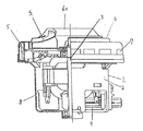
従来の電動送風機について図15を用いて説明する。
【0003】
従来のこの種の電動送風機は、モータ部2の回転軸3にインペラ4を取付固定した電動送風機である。前記インペラ4の外周に対向してエアガイド5が配置されている。6はインペラ4とエアガイド5を内包し、かつモータ部2の外周に気密に取り付けられた中央部に吸気孔6aを有するケーシングである。前記ケーシング6の外周には複数個の排気部A7が設けられている。また、モータ部2を構成するブラケット8には排気部B9が設けられている。
【0004】
以上の構成における動作について説明すると、モータ部2が運転し、回転軸3に取付固定されたインペラ4が高速で回転すると吸込まれる気流が発生し、この気流はインペラ4の外周より排出されエアガイド5を経由して、気流の一部はケーシング6の外周に設けられた排気部A7から外部に排出され、その他の気流はブラケット8の排気部B9から排出されるものであった(特許文献1参照。)。
【0005】
【特許文献1】
実開昭61−47964公報
【0006】
【発明が解決しようとする課題】
しかしながら、このように吸込んだ気流の一部をケーシング6の外周から排出させることにより、電動送風機1の送風効率が向上することは以前から知られていたが、具体的な排気部7の面積や形状、エアガイド5との相対位置関係等については詳しく述べられていなかった。
【0007】
本発明は上記の課題に対して、送風効率を高めた電動送風機及びそれを有する電気掃除機を提供することを目的とするものである。
【0008】
【課題を解決するための手段】
上記目的を達成するために本発明は、ステータと自在に回転するロータと、前記ロータの回転軸に設けられたインペラと、前記インペラの周囲に複数の案内翼を有するエアガイドと、前記インペラ及び前記エアガイドを覆うケーシングとを備え、前記ケーシングの外周に、前記インペラにより吸引された気流の一部を排出する排気部を設けるとともに、前記排気部の外周方向の幅の長さは、隣り合う案内翼の外周端間の距離と略同一にしたもので、送風効率を著しく向上できるものである。
【0009】
【発明の実施の形態】
本発明の請求項1記載の発明は、ステータと自在に回転するロータと、前記ロータの回転軸に設けられたインペラと、前記インペラの周囲に複数の案内翼を有するエアガイドと、前記インペラ及び前記エアガイドを覆うケーシングとを備え、前記ケーシングの外周に、前記インペラにより吸引された気流の一部を排出する排気部を設けるとともに、前記排気部の外周方向の幅の長さは、隣り合う案内翼の外周端間の距離と略同一にしたもので、排気がスムーズに排出されて送風効率が向上するものである。
【0010】
本発明の請求項2記載の発明は、ステータと自在に回転するロータと、前記ロータの回転軸に設けられたインペラと、前記インペラの周囲に複数の案内翼を有するエアガイドと、前記インペラ及び前記エアガイドを覆うケーシングとを備え、前記ケーシングの外周に、前記インペラにより吸引された気流の一部を排出する排気部を設けるとともに、前記排気部の外周方向の幅の長さは、隣り合う案内翼の外周端間の距離より小さくしたもので、高周波音などの騒音を抑制することができるものである。
【0011】
本発明の請求項3記載の発明は、ステータと自在に回転するロータと、前記ロータの回転軸に設けられたインペラと、前記インペラの周囲に複数の案内翼を有するエアガイドと、前記インペラ及び前記エアガイドを覆うケーシングとを備え、前記ケーシングの外周に、前記インペラにより吸引された気流の一部を排出する排気部を設けるとともに、前記排気部の外周方向の幅の長さは、隣り合う案内翼の外周端間の距離より大きくしたもので、隣り合う案内翼によって形成されたボリュート室からの排気同士が干渉しあって高周波音を抑制することができるものである。
【0012】
本発明の請求項4記載の発明は、排気部の面積を40mm2以上に設定したもので、送風効率を向上できるものである。
【0013】
本発明の請求項5記載の発明は、エアガイドの外周とケーシングの内周との間に隙間を設けたもので、前記隙間で気流の還流が僅かに発生して、気流の干渉により高周波音を抑制することができるものである。
【0014】
本発明の請求項6記載の発明は、案内翼が排気部の外周方向の幅の略中央部に位置するように配されたもので、隣り合う案内翼によって形成されたボリュート室からの排気同士が干渉しあって高周波音を抑制することができるものである。
【0015】
本発明の請求項7記載の発明は、排気部の気流排出側のケーシングにリブを設けたもので、ケーシングからの排気が空気流の下流側に強制的に流れるようにして送風効率を向上できるものである。
【0016】
本発明の請求項8記載の発明は、排気部の上下方向両端壁の傾斜を、隣り合う案内翼を連結して形成ボリュート室の底面の傾斜と略同一としたもので、スムーズに気流が排出されて送風効率が向上できるものである。
【0017】
本発明の請求項9記載の発明は、排気部の上下方向両端壁の傾斜を、回転軸の長手方向に対して傾斜させたもので、スムーズに電動機の下流側に気流が流れるようにして送風効率を向上できるものである。
【0018】
本発明の請求項10記載の発明は、排気部をケーシングの半周部以内に設けたもので、高周波音を抑制できるものである。
【0019】
本発明の請求項11記載の発明は、隣り合う案内翼を連結して形成ボリュート室の数と、排気部との数を同一にしたもので、気流のスムーズな排出ができ送風効率が向上できるものである。
【0020】
本発明の請求項12記載の発明は、略四角状の排気部の上下方向の壁を、回転軸の長手方向に対して傾斜させ、面積を小さくしたもので、高周波音の抑制をしながら送風効率を向上できるものである。
【0021】
本発明の請求項13記載の発明は、ステータと自在に回転するロータと、前記ロータの回転軸に設けられたインペラと、前記インペラを覆うケーシングを備え、前記ケーシングの外周に、前記インペラにより吸引された気流の一部を排出する小孔形状なる排気部を多数個設けたもので、高周波音の抑制をしながら送風効率を向上できるものである。
【0022】
本発明の請求項14記載の発明は、ケーシングの外周に、排気部を覆いかつ下流側に開口を有するモータカバーを設けたもので、送風効率を向上できるものである。
【0023】
本発明の請求項15記載の発明は、ケーシングの外周に、排気部を覆いかつステータ側に開口を有するモータカバーを設けるとともに、前記モータカバーは、排気部と対向した位置にスクロール形状の羽根を有するもので、更に送風効率を向上できるものである。
【0024】
本発明の請求項16記載の発明は、塵埃を捕集する集塵室を備え、請求項1〜15のいずれか1項に記載の電動送風機を内蔵した電気掃除機で、電動送風機の送風効率を向上させて吸込み力の強い電気掃除機を実現できるものである。
【0025】
【実施例】
(実施例1)
以下、本発明の第1の実施例を、図1、図2を用いて説明する。
【0026】
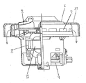
1は、モータ部2とファン部10から成る電動送風機である。前記モータ部2は、負荷側の軸受け11を保持するブラケットA12と、反負荷側の軸受け13を保持するブラケットB14とから外郭を構成し、前記ブラケットB14内には、回転軸3に整流子15と薄い珪素鋼板を積層して成る電機子コア16を圧入固定し、巻線(図示せず)を施したロータ17と、薄い珪素鋼板を積層して成る界磁コア18に巻線(図示せず)を施したステータ19を内蔵している。また、前記ブラケットB14には整流子15と摺動するカーボンブラシ(図示せず)を収納したブラシホルダー20を設けている。前記ファン部10は、前記回転軸3に、一対の前面シュラウド21と後面シュラウド22によって複数枚のブレード23を挟持固定して構成されたインペラ4が取付固定されている。前面シュラウド21の中央部に吸気孔21aが設けられている。また、前記インペラ4の外周には、複数の案内翼24で形成したボリュート室25を有するエアガイド5を配置している。6はインペラ4とエアガイド5を内包し、かつブラケットB14の外周に気密に取り付けられた中央部に吸気孔6aを有するケーシングであり、その外周にはエアガイド5を経由した気流の一部が排出される排気部A7が設けられている。また、ブラケットB14には排気部B9が設けられている。
【0027】
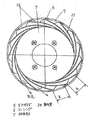
ここで、前記ケーシング6に設けられた排気部A7の外周方向の長さAと、エアガイド5に設けられた隣り合う案内翼24の外周端での距離Bが略同一で対向して設けられている。つまり、前記隣り合う案内翼24の外周端に対向するケーシング6に、略四角形の排気部B9が形成されている。
【0028】
上記構成による作用は以下の通りである。
【0029】
まず、電力がモータ部2のカ−ボンブラシ24及び整流子9を経由してロータ17の巻線とステータ19の巻線に供給されてモータ部2が運転し、ロータ17の回転軸3が高速で回転し、回転軸3に固定されたインペラ4が高速で回転する。その結果発生した気流は、前記インペラ4の前面シュラウド21に設けた吸込み口21aから吸込まれ、前面、後面シュラウド21、22と複数のブレード23で囲まれた空間を通ってインペラ4外周より排出される。そして、インペラ4より排出された気流は、エアガイド5に設けられた隣り合う複数の案内翼24で構成されるボリュート室25を通ってエアガイド5の外周より排出される。
【0030】
このエアガイド5の外周から排出された気流の一部はケーシング6に設けられた排気部A7から外部へ排出され、残りの気流はブラケットB14内に内蔵されたロータ17、ステータ19等を冷却した後にブラケットB14に設けられた排気部B9から外部に排出されるものである。
【0031】
ここで、吸込まれた気流の一部がケーシング6に設けられた排気部A7から直接外部に排出されるので、エアガイド5に形成されたボリュート室25を経由してエアガイド5の裏面へ導かれる際に生じる気流の屈曲による圧力損失(曲がり損失)が低減される。
【0032】
また、同時にモータ部2内を通過する気流が減少するので、その際に生じる抵抗による圧力損失(風損)も低減される。従って上記「曲がり損失」と「風損」の流体的損失が低減できるので全体の送風効率が向上するものである。
【0033】
この時、排気部A7の外周方向の長さAと、エアガイド5に設けられた隣り合う案内翼24の外周端での距離Bが略同一、つまり、前記隣り合う案内翼24の外周端に対向するケーシング6に、略四角形の排気部B9が対向して設けられているので、ボリュート室25内を通った気流が効率良くスムーズに排気部A7より排出され、モータ部2内を通過する気流が減少する。その結果「曲がり損」と「風損」の損失が減少するため更に送風効率が向上するものである。
【0034】
(実施例2)
次に本発明の第2の実施例を、図3を用いて説明する。なお上記実施例と同一構成部品については同一符号を付してその説明を省略する。
【0035】
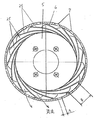
ケーシング6に設けられた排気部A7の外周方向の長さAが、エアガイド5に設けられた隣り合う案内翼24の外周端での距離Bよりも小さくなる関係にして、排気部A7とボリュート室25が対向するように配置されている。
【0036】
なお、前記排気部A7は前記ボリュート室25の略中央対向位置に設けられている。
【0037】
上記構成による作用は以下の通りである。
【0038】
ケーシング6に設けられた排気部A7から気流が直接排出されるため高周波音が増大する傾向がある。そこで排気部A7の面積を小さめにすることによりモータ部2内を通過する気流を増加させて高周波音の抑制を図れるものである。
【0039】
当然ながら排気部A7の数を減らしたり、ケーシング6のどちらか一方向の半周のみに排気部A7を設けても同様の効果が得られる事は言うまでもない。
【0040】
(実施例3)
次に本発明の第3の実施例を、図4を用いて説明する。なお上記実施例と同一構成部品については同一符号を付してその説明を省略する。
【0041】
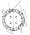
ケーシング6に設けられた排気部A7の外周方向の長さAが、エアガイド5に設けられた隣り合う案内翼24の外周端での距離Bよりも大きくなる関係にしている。なお、前記排気部A7の外周方向の両端を形成する壁は、前記ボリュート室25の略中央対向位置に設けられている。
【0042】
上記構成による作用は以下の通りである。
【0043】
ケーシング6に設けられた排気部Aから気流が直接排出されるため高周波音が増大する傾向がある。そこで排気部A7の外周方向の長さAを、エアガイド5に設けた隣り合う案内翼24の外周端での距離Bよりも大きくなるように設定し、一つの排気部A7に対して複数のボリュート室25が対向するように配置することにより、隣同士のボリュート室25から排出された気流がケーシング6外周より排出されると同時に混ざり合い高周波音を打ち消す効果が図れるものである。
【0044】
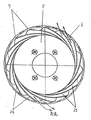
これは図5に示すように排気部A7の中間にエアガイド5の案内翼25が位置するように設定したり、エガイド5の外周とケーシング6の内周との間に隙間を設けて僅かに還流を発生させることでも同様の効果が得られる。
【0045】
また、排気部A7の形状を、図6に示すようなスリット形状や、図7に示すような多数個の小孔にしても同様な効果が得られる。
【0046】
(実施例4)
次に本発明の第4の実施例を、図8を用いて説明する。なお上記実施例と同一構成部品については同一符号を付してその説明を省略する。
【0047】
ケーシング6の外周に設けた排気部A7の面積を40mm2以上に設定したものである。
【0048】
上記構成による作用は以下の通りである。
【0049】
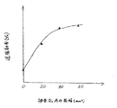
前に述べたようにケーシング6に設けた排気部A7の面積が大きいほど流体的損失が低減できて全体の送風効率を向上できるが、図8のグラフに示すように排気部A7の面積が約40mm2以上になるとその効果がサチレートしてくる。グラフの横軸は排気部A7の面積で、縦軸が送風効率である。
【0050】
(実施例5)
次に本発明の第5の実施例を、図9を用いて説明する。なお上記実施例と同一構成部品については同一符号を付してその説明を省略する。
【0051】
ケーシング6の外周に設けた排気部A7のケーシング6の気流排出側にリブ26を設けている。
【0052】
上記構成による作用は以下の通りである。
【0053】
排気部A7に設けたリブ26により、ケーシング6の排気部A7から排出された気流は排出されると同時に拡散することなくモータ部2側、いわゆる空気流の下流側に強制的に流れるようになる。その結果、スムーズな気流となり気流の排出量が増加して流体的損失を低減して送風効率を向上させることができる。
【0054】
(実施例6)
次に本発明の第6の実施例を、図10を用いて説明する。なお上記実施例と同一構成部品については同一符号を付してその説明を省略する。
【0055】
エアガイド5に設けた隣り合う案内翼24で形成されるボリュート室25の底面部25aの傾斜と、略四角形の排気部A7の上下方向両端壁の傾斜が略同一となるよう構成している。
【0056】
上記構成による作用は以下の通りである。
【0057】
ケーシング6に設けられた排気部A7は、ボリュート室25から排出される気流の角度と略同一の角度で斜めに開口しているので気流の流れがスムーズになる。
【0058】
その結果、上記の実施例と同様に気流の排出量が増加して流体的損失を低減して送風効率を向上させることができる。これは、図11のように略四角状の排気部A7の上下方向の壁を、回転軸3の長手方向に対して傾斜させ、面積を小さくして形成することでも同様な効果が得られる。
【0059】
(実施例7)
次に本発明の第7の実施例を、図12を用いて説明する。なお上記実施例と同一構成部品については同一符号を付してその説明を省略する。
【0060】
排気部A7を覆いかつ下流側に開口を有するモータカバー27を設けることで、排気部A7から排出された気流を、モータ部2側、いわゆる空気流の下流側にスムーズに流れるようしているものである。
【0061】
上記構成による作用は以下の通りである。
【0062】
ケーシング6の外周に配設したモータカバー27により、ケーシング6の排気部A7から排出された気流が排出されると同時に拡散するのを防止しできるので、気流はモータ部2の下流側にスムーズに流れる。その結果、気流の排出量が増加して流体的損失を低減するので送風効率を向上させることができる。
【0063】
また、図13のようにモータカバー27に、ケーシング6の排気部A7と対向した位置にスクロ−ル状の羽根28を設けることにより更に送風効率を向上できる事は言うまでもない。
【0064】
(実施例8)
次に本発明の第8の実施例を、図14を用いて説明する。なお上記実施例と同一構成部品については同一符号を付してその説明を省略する。
【0065】
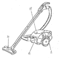
28は、塵埃を捕集する集塵室29と、前記集塵室29に連通するように接続される吸い込み部30と請求項1〜15のいずれか1項記載の電動送風機1を備えた電気掃除機である。
【0066】
上記構成による作用は以下の通りである。
【0067】
電動送風機1の送風効率を向上させて吸込み力の強い電気掃除機30を実現できるものである。
【0068】
【発明の効果】
本発明によれば、送風効率を高めた電動送風機及びそれを有する電気掃除機を提供できる。
【図面の簡単な説明】
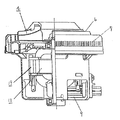
【図1】本発明の第1の実施例を示す電動送風機の半断面図
【図2】同電動送風機の案内翼と排気部Aの位置関係を示す横断面図(図1のC−C断面図)
【図3】本発明の第2の実施例の案内翼と排気部Aの位置関係を示す横断面図(図1のC−C断面図)
【図4】本発明の第3の実施例の案内翼と排気部Aの位置関係を示す横断面図(図1のC−C断面図)
【図5】同電動送風機の案内翼と排気部Aの位置関係を示す横断面図(図1のC−C断面図)
【図6】同電動送風機の半断面図
【図7】同他の電動送風機の半断面図
【図8】本発明の第4の実施例の排気部A面積と送風効率の関係を示すグラフ
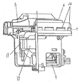
【図9】本発明の第5の実施例を示す電動送風機の半断面図
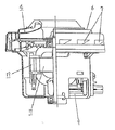
【図10】本発明の第6の実施例を示す電動送風機の半断面図
【図11】同他の電動送風機の半断面図
【図12】本発明の第7の実施例を示す電動送風機の半断面図
【図13】同他の電動送風機の下方斜視図
【図14】本発明の第7の実施例を示す電気掃除機全体の斜視図
【図15】従来の電動送風機の半断面図
【符号の説明】
1 電動送風機
2 電動機
3 回転軸
4 インペラ
5 エアガイド
6 ケーシング
6a 吸気孔
7 排気部A
8 ブラケット
9 排気部B
10 ファンユニット
17 ロータ
19 ステータ
24 案内翼
25 ボリュート室
26 リブ
27 モータカバー
28 電気掃除機
29 集塵室
30 吸込み部[0001]
TECHNICAL FIELD OF THE INVENTION
The present invention relates to an electric blower and a vacuum cleaner.
[0002]
[Prior art]
A conventional electric blower will be described with reference to FIG.
[0003]
This type of conventional electric blower is an electric blower in which an
[0004]
The operation in the above configuration will be described. When the
[0005]
[Patent Document 1]
Published Japanese Utility Model Application No. 61-47964
[Problems to be solved by the invention]
However, it has been known for some time that the air flow efficiency of the
[0007]
It is an object of the present invention to provide an electric blower with improved blowing efficiency and a vacuum cleaner having the same for the above-mentioned problems.
[0008]
[Means for Solving the Problems]
In order to achieve the above object, the present invention provides a rotor that freely rotates with a stator, an impeller provided on a rotating shaft of the rotor, an air guide having a plurality of guide vanes around the impeller, the impeller, A casing that covers the air guide, and an exhaust unit that exhausts a part of the airflow sucked by the impeller is provided on the outer periphery of the casing, and the width of the exhaust unit in the outer peripheral direction is adjacent to the exhaust unit. The distance between the outer peripheral ends of the guide vanes is substantially equal to that of the guide vanes, so that the blowing efficiency can be significantly improved.
[0009]
BEST MODE FOR CARRYING OUT THE INVENTION
The invention according to
[0010]
According to a second aspect of the present invention, there is provided a rotor freely rotating with a stator, an impeller provided on a rotation shaft of the rotor, an air guide having a plurality of guide vanes around the impeller, the impeller, and A casing that covers the air guide, and an exhaust unit that exhausts a part of the airflow sucked by the impeller is provided on the outer periphery of the casing, and the width of the exhaust unit in the outer peripheral direction is adjacent to the exhaust unit. This is smaller than the distance between the outer peripheral ends of the guide vanes, and can suppress noise such as high-frequency sound.
[0011]
According to a third aspect of the present invention, there is provided a rotor freely rotating with a stator, an impeller provided on a rotating shaft of the rotor, an air guide having a plurality of guide vanes around the impeller, the impeller, A casing that covers the air guide, and an exhaust unit that exhausts a part of the airflow sucked by the impeller is provided on the outer periphery of the casing, and the width of the exhaust unit in the outer peripheral direction is adjacent to the exhaust unit. The distance between the outer peripheral ends of the guide vanes is larger than that of the guide vanes. Exhaust gas from the volute chamber formed by adjacent guide vanes interferes with each other to suppress high-frequency noise.
[0012]
According to the invention of
[0013]
According to a fifth aspect of the present invention, a gap is provided between the outer periphery of the air guide and the inner periphery of the casing. Can be suppressed.
[0014]
In the invention according to
[0015]
In the invention according to
[0016]
According to the eighth aspect of the present invention, the inclination of both end walls in the vertical direction of the exhaust unit is substantially the same as the inclination of the bottom surface of the formed volute chamber by connecting the adjacent guide vanes, so that the air flow is smoothly discharged. Thus, the blowing efficiency can be improved.
[0017]
According to a ninth aspect of the present invention, the upper and lower end walls of the exhaust portion are inclined with respect to the longitudinal direction of the rotating shaft, so that air flows smoothly downstream of the electric motor. It can improve efficiency.
[0018]
According to a tenth aspect of the present invention, the exhaust portion is provided within a half circumference of the casing, and high-frequency sound can be suppressed.
[0019]
According to the eleventh aspect of the present invention, the number of volute chambers formed by connecting adjacent guide vanes and the number of exhaust portions are made the same, so that the air flow can be smoothly discharged and the blowing efficiency can be improved. Things.
[0020]
According to a twelfth aspect of the present invention, the vertical wall of the substantially rectangular exhaust portion is inclined with respect to the longitudinal direction of the rotating shaft to reduce the area, and the air is blown while suppressing high-frequency sound. It can improve efficiency.
[0021]
According to a thirteenth aspect of the present invention, there is provided a rotor that freely rotates with a stator, an impeller provided on a rotation shaft of the rotor, and a casing that covers the impeller, and the outer periphery of the casing is suctioned by the impeller. A large number of small-hole-shaped exhaust portions for discharging a part of the generated air current are provided, and the blowing efficiency can be improved while suppressing high-frequency sound.
[0022]
According to a fourteenth aspect of the present invention, a motor cover that covers the exhaust portion and has an opening on the downstream side is provided on the outer periphery of the casing, so that the blowing efficiency can be improved.
[0023]
The invention according to claim 15 of the present invention provides a motor cover that covers an exhaust portion and has an opening on a stator side on an outer periphery of a casing, and the motor cover has scroll-shaped blades at a position facing the exhaust portion. It can further improve the blowing efficiency.
[0024]
According to a sixteenth aspect of the present invention, there is provided a vacuum cleaner including a dust collecting chamber for collecting dust, and a built-in electric blower according to any one of the first to fifteenth aspects. And a vacuum cleaner having a strong suction force can be realized.
[0025]
【Example】
(Example 1)
Hereinafter, a first embodiment of the present invention will be described with reference to FIGS.
[0026]
[0027]
Here, the length A in the outer peripheral direction of the exhaust portion A7 provided in the
[0028]
The operation of the above configuration is as follows.
[0029]
First, electric power is supplied to the winding of the
[0030]
A part of the airflow discharged from the outer periphery of the
[0031]
Here, a part of the sucked airflow is directly discharged to the outside from the exhaust part A7 provided in the
[0032]
At the same time, since the airflow passing through the
[0033]
At this time, the length A of the exhaust portion A7 in the outer peripheral direction is substantially the same as the distance B at the outer peripheral end of the
[0034]
(Example 2)
Next, a second embodiment of the present invention will be described with reference to FIG. The same components as those in the above embodiment are denoted by the same reference numerals, and description thereof will be omitted.
[0035]
The relationship between the length A in the outer peripheral direction of the exhaust portion A7 provided in the
[0036]
Note that the exhaust portion A7 is provided at a position substantially opposite the center of the
[0037]
The operation of the above configuration is as follows.
[0038]
Since the airflow is directly discharged from the exhaust part A7 provided in the
[0039]
It goes without saying that the same effect can be obtained even if the number of the exhaust portions A7 is reduced or the exhaust portions A7 are provided in only one half of the
[0040]
(Example 3)
Next, a third embodiment of the present invention will be described with reference to FIG. The same components as those in the above embodiment are denoted by the same reference numerals, and description thereof will be omitted.
[0041]
The length A in the outer peripheral direction of the exhaust portion A7 provided in the
[0042]
The operation of the above configuration is as follows.
[0043]
Since the airflow is directly discharged from the exhaust portion A provided in the
[0044]
This is done by setting the
[0045]
The same effect can be obtained by changing the shape of the exhaust portion A7 to a slit shape as shown in FIG. 6 or a large number of small holes as shown in FIG.
[0046]
(Example 4)
Next, a fourth embodiment of the present invention will be described with reference to FIG. The same components as those in the above embodiment are denoted by the same reference numerals, and description thereof will be omitted.
[0047]
The area of the exhaust portion A7 provided on the outer periphery of the
[0048]
The operation of the above configuration is as follows.
[0049]
As described above, as the area of the exhaust portion A7 provided in the
[0050]
(Example 5)
Next, a fifth embodiment of the present invention will be described with reference to FIG. The same components as those in the above embodiment are denoted by the same reference numerals, and description thereof will be omitted.
[0051]
A
[0052]
The operation of the above configuration is as follows.
[0053]
Due to the
[0054]
(Example 6)
Next, a sixth embodiment of the present invention will be described with reference to FIG. The same components as those in the above embodiment are denoted by the same reference numerals, and description thereof will be omitted.
[0055]
The inclination of the bottom surface 25a of the
[0056]
The operation of the above configuration is as follows.
[0057]
Since the exhaust portion A7 provided in the
[0058]
As a result, similarly to the above-described embodiment, the amount of discharged airflow is increased, the fluid loss is reduced, and the blowing efficiency can be improved. The same effect can be obtained by forming the substantially rectangular exhaust portion A7 in the vertical direction as shown in FIG. 11 so that the vertical wall is inclined with respect to the longitudinal direction of the
[0059]
(Example 7)
Next, a seventh embodiment of the present invention will be described with reference to FIG. The same components as those in the above embodiment are denoted by the same reference numerals, and description thereof will be omitted.
[0060]
By providing a
[0061]
The operation of the above configuration is as follows.
[0062]
The
[0063]
It is needless to say that the
[0064]
(Example 8)
Next, an eighth embodiment of the present invention will be described with reference to FIG. The same components as those in the above embodiment are denoted by the same reference numerals, and description thereof will be omitted.
[0065]
28. An electric device comprising: a
[0066]
The operation of the above configuration is as follows.
[0067]
This improves the air-blowing efficiency of the
[0068]
【The invention's effect】
Advantageous Effects of Invention According to the present invention, it is possible to provide an electric blower with improved blowing efficiency and a vacuum cleaner having the same.
[Brief description of the drawings]
FIG. 1 is a half sectional view of an electric blower showing a first embodiment of the present invention; FIG. 2 is a transverse sectional view showing a positional relationship between a guide blade and an exhaust portion A of the electric blower (a sectional view taken along line CC in FIG. 1); (Fig.)
FIG. 3 is a cross-sectional view showing a positional relationship between a guide vane and an exhaust portion A according to a second embodiment of the present invention (a cross-sectional view taken along line CC in FIG. 1).
FIG. 4 is a cross-sectional view showing a positional relationship between a guide vane and an exhaust portion A according to a third embodiment of the present invention (a cross-sectional view taken along line CC in FIG. 1).
FIG. 5 is a cross-sectional view showing a positional relationship between a guide blade and an exhaust portion A of the electric blower (a cross-sectional view taken along line CC in FIG. 1).
FIG. 6 is a half sectional view of the electric blower. FIG. 7 is a half sectional view of another electric blower. FIG. 8 is a graph showing the relationship between the area of the exhaust section A and the blowing efficiency according to the fourth embodiment of the present invention. FIG. 9 is a half sectional view of an electric blower showing a fifth embodiment of the present invention. FIG. 10 is a half sectional view of an electric blower showing a sixth embodiment of the present invention. FIG. 11 is a half sectional view of another electric blower. FIG. 12 is a half sectional view of an electric blower showing a seventh embodiment of the present invention. FIG. 13 is a lower perspective view of another electric blower. FIG. 14 is an electric diagram showing a seventh embodiment of the present invention. 15 is a perspective view of the entire vacuum cleaner. FIG. 15 is a half sectional view of a conventional electric blower.
DESCRIPTION OF
8
10
Claims (16)
Priority Applications (14)
| Application Number | Priority Date | Filing Date | Title |
|---|---|---|---|
| JP2002274546A JP2004108317A (en) | 2002-09-20 | 2002-09-20 | Electric blower and vacuum cleaner using the same |
| AT06018585T ATE420293T1 (en) | 2002-09-20 | 2003-09-18 | ELECTRIC FAN AND VACUUM CLEANER EQUIPPED THEREOF |
| AT03021203T ATE382121T1 (en) | 2002-09-20 | 2003-09-18 | ELECTRIC FAN AND VACUUM CLEANER EQUIPPED THEREOF |
| DE60318286T DE60318286T2 (en) | 2002-09-20 | 2003-09-18 | Electric blower and vacuum cleaner equipped therewith |
| ES06018585T ES2320795T3 (en) | 2002-09-20 | 2003-09-18 | ELECTRIC BLOWER AND VACUUM CLEANER PROVIDED OF THE SAME. |
| DE60325790T DE60325790D1 (en) | 2002-09-20 | 2003-09-18 | Electric blower and vacuum cleaner equipped therewith |
| EP06018586A EP1731767A3 (en) | 2002-09-20 | 2003-09-18 | Electric blower and vacuum cleaner using the same |
| ES03021203T ES2297084T3 (en) | 2002-09-20 | 2003-09-18 | ELECTRIC BLOWER AND VACUUM CLEANER PROVIDED OF THE SAME. |
| DK03021203T DK1400699T3 (en) | 2002-09-20 | 2003-09-18 | Electric fan and vacuum cleaner using it |
| EP06018585A EP1736670B1 (en) | 2002-09-20 | 2003-09-18 | Electric blower and vacuum cleaner using the same |
| CNB03158988XA CN1311167C (en) | 2002-09-20 | 2003-09-18 | Electric fan and electric dust collector using said fan |
| EP03021203A EP1400699B1 (en) | 2002-09-20 | 2003-09-18 | Electric blower and vacuum cleaner using the same |
| CNU032078994U CN2704707Y (en) | 2002-09-20 | 2003-09-19 | Electric blower and electric vacuum cleaner using the same |
| US10/664,975 US7416384B2 (en) | 2002-09-20 | 2003-09-22 | Electric blower and vacuum cleaner using same |
Applications Claiming Priority (1)
| Application Number | Priority Date | Filing Date | Title |
|---|---|---|---|
| JP2002274546A JP2004108317A (en) | 2002-09-20 | 2002-09-20 | Electric blower and vacuum cleaner using the same |
Publications (1)
| Publication Number | Publication Date |
|---|---|
| JP2004108317A true JP2004108317A (en) | 2004-04-08 |
Family
ID=32270986
Family Applications (1)
| Application Number | Title | Priority Date | Filing Date |
|---|---|---|---|
| JP2002274546A Pending JP2004108317A (en) | 2002-09-20 | 2002-09-20 | Electric blower and vacuum cleaner using the same |
Country Status (1)
| Country | Link |
|---|---|
| JP (1) | JP2004108317A (en) |
Cited By (6)
| Publication number | Priority date | Publication date | Assignee | Title |
|---|---|---|---|---|
| JP2007002769A (en) * | 2005-06-24 | 2007-01-11 | Hitachi Appliances Inc | Electric blower and vacuum cleaner equipped with the same |
| JP2007002770A (en) * | 2005-06-24 | 2007-01-11 | Hitachi Appliances Inc | Electric blower and vacuum cleaner equipped with the same |
| CN100432449C (en) * | 2005-01-19 | 2008-11-12 | 乐金电子(天津)电器有限公司 | Impeller cover of centrifugal fan |
| JP2012193679A (en) * | 2011-03-17 | 2012-10-11 | Mitsubishi Electric Corp | Electric blower |
| JP2019094825A (en) * | 2017-11-22 | 2019-06-20 | 日立アプライアンス株式会社 | Electric blower and vacuum cleaner mounting the same |
| CN113446264A (en) * | 2020-03-26 | 2021-09-28 | 日立环球生活方案株式会社 | Fan and washing machine |
Citations (6)
| Publication number | Priority date | Publication date | Assignee | Title |
|---|---|---|---|---|
| JPH0584169A (en) * | 1991-09-26 | 1993-04-06 | Matsushita Electric Ind Co Ltd | Electrically-driven blower |
| JPH11113809A (en) * | 1997-10-08 | 1999-04-27 | Matsushita Electric Ind Co Ltd | Electric vacuum cleaner |
| JP2001003898A (en) * | 1999-06-23 | 2001-01-09 | Sanyo Electric Co Ltd | Electric blower and vacuum cleaner using it |
| JP2001012395A (en) * | 1999-06-25 | 2001-01-16 | Sanyo Electric Co Ltd | Electric fan |
| JP2001271794A (en) * | 2000-03-28 | 2001-10-05 | Matsushita Electric Ind Co Ltd | Electric blower and vacuum cleaner using it |
| JP2001340272A (en) * | 2000-03-31 | 2001-12-11 | Sanyo Electric Co Ltd | Vacuum cleaner |
-
2002
- 2002-09-20 JP JP2002274546A patent/JP2004108317A/en active Pending
Patent Citations (6)
| Publication number | Priority date | Publication date | Assignee | Title |
|---|---|---|---|---|
| JPH0584169A (en) * | 1991-09-26 | 1993-04-06 | Matsushita Electric Ind Co Ltd | Electrically-driven blower |
| JPH11113809A (en) * | 1997-10-08 | 1999-04-27 | Matsushita Electric Ind Co Ltd | Electric vacuum cleaner |
| JP2001003898A (en) * | 1999-06-23 | 2001-01-09 | Sanyo Electric Co Ltd | Electric blower and vacuum cleaner using it |
| JP2001012395A (en) * | 1999-06-25 | 2001-01-16 | Sanyo Electric Co Ltd | Electric fan |
| JP2001271794A (en) * | 2000-03-28 | 2001-10-05 | Matsushita Electric Ind Co Ltd | Electric blower and vacuum cleaner using it |
| JP2001340272A (en) * | 2000-03-31 | 2001-12-11 | Sanyo Electric Co Ltd | Vacuum cleaner |
Cited By (7)
| Publication number | Priority date | Publication date | Assignee | Title |
|---|---|---|---|---|
| CN100432449C (en) * | 2005-01-19 | 2008-11-12 | 乐金电子(天津)电器有限公司 | Impeller cover of centrifugal fan |
| JP2007002769A (en) * | 2005-06-24 | 2007-01-11 | Hitachi Appliances Inc | Electric blower and vacuum cleaner equipped with the same |
| JP2007002770A (en) * | 2005-06-24 | 2007-01-11 | Hitachi Appliances Inc | Electric blower and vacuum cleaner equipped with the same |
| JP2012193679A (en) * | 2011-03-17 | 2012-10-11 | Mitsubishi Electric Corp | Electric blower |
| JP2019094825A (en) * | 2017-11-22 | 2019-06-20 | 日立アプライアンス株式会社 | Electric blower and vacuum cleaner mounting the same |
| CN113446264A (en) * | 2020-03-26 | 2021-09-28 | 日立环球生活方案株式会社 | Fan and washing machine |
| CN113446264B (en) * | 2020-03-26 | 2024-03-08 | 日立环球生活方案株式会社 | Fan and washing machine |
Similar Documents
| Publication | Publication Date | Title |
|---|---|---|
| JP2003139094A (en) | Electric blower for vacuum cleaner and vacuum cleaner using the same | |
| CN116391080A (en) | Electric fan and electric vacuum cleaner with it | |
| CN101608630B (en) | Electric blower and electric duct collector equipped with the same | |
| CN100575714C (en) | Electric blower | |
| JP2004108317A (en) | Electric blower and vacuum cleaner using the same | |
| JPH1026099A (en) | Electric blower | |
| JP3581301B2 (en) | Electric blower | |
| EP3643925A1 (en) | Electric air blower, electric vacuum cleaner, and hand drier device | |
| JPH11125198A (en) | Electric blower | |
| CN100390424C (en) | Electric fan and vacuum cleaner using the same | |
| JPH1068397A (en) | Electric blower | |
| JP4140330B2 (en) | Electric blower and electric vacuum cleaner using the same | |
| JP4029333B2 (en) | Electric blower | |
| JP2007192034A (en) | Electric blower and electric vacuum cleaner using the same | |
| JPH11125197A (en) | Electric blower | |
| JP2005220853A (en) | Electric blower | |
| JP2001271794A (en) | Electric blower and vacuum cleaner using it | |
| JP7795026B2 (en) | Electric blower and electric vacuum cleaner equipped with same | |
| JP2007146746A (en) | Electric blower and electric vacuum cleaner using the same | |
| JP2004169592A (en) | Electric blower and vacuum cleaner using the same | |
| WO2019176625A1 (en) | Electric blower, electric cleaner, and air towel | |
| CN223104879U (en) | High-flow fan structure | |
| JP2681973B2 (en) | Electric blower | |
| JPH11173297A (en) | Electric vacuum cleaner | |
| JP2026007783A (en) | Electric blower and vacuum cleaner equipped with same |
Legal Events
| Date | Code | Title | Description |
|---|---|---|---|
| A621 | Written request for application examination |
Free format text: JAPANESE INTERMEDIATE CODE: A621 Effective date: 20041216 |
|
| RD01 | Notification of change of attorney |
Free format text: JAPANESE INTERMEDIATE CODE: A7421 Effective date: 20050707 |
|
| A977 | Report on retrieval |
Free format text: JAPANESE INTERMEDIATE CODE: A971007 Effective date: 20070807 |
|
| A131 | Notification of reasons for refusal |
Free format text: JAPANESE INTERMEDIATE CODE: A131 Effective date: 20070821 |
|
| A02 | Decision of refusal |
Free format text: JAPANESE INTERMEDIATE CODE: A02 Effective date: 20071218 |