【0001】
【発明の属する技術分野】
本発明は、例えば、下水や屎尿等の汚水、河川や湖沼等の水中に存在しているリン酸及びリン酸塩(以下、単に「リン」という)を除去する場合に用いられる脱リン材及びその製造方法に関するものである。
【0002】
【従来の技術】
近年、環境保全や水資源の確保は非常に重要な社会問題となっており、水処理に際して要求される技術的内容及び範囲はますます高度化、多様化する傾向にある。そして、水質の富栄養化現象をもたらす原因物質としてリンが知られており、このリンを水中から除去することが強く要望されている。
【0003】
そこで従来、水中のリンを除去する方法として、凝集沈殿法が一般に用いられている(例えば、非特許文献1参照)。この凝集沈殿法は、リンを含有した水に対して石灰、鉄、アルミニウム等の凝集剤を添加して難溶性のリン化合物(以下、「スラッジ」という)を生成し、該スラッジを沈殿させてリンを除去するようにしたものである。
【0004】
【非特許文献1】
山本 康次 著、「し尿浄化槽における窒素・リン除去処理」、環境技術、1982年、Vol.11、No.11、p.843
【0005】
【発明が解決しようとする課題】
しかしながら、上述した従来技術に係る凝集沈殿法では、多量の凝集剤を必要とするため、スラッジの生成量が多くなると共に、生成したスラッジは、沈降性が悪いため、該スラッジが沈殿しにくいという問題がある。
【0006】
本発明は、上述した実情に鑑みてなされたものであり、その目的は、水中のリンをスラッジに変え、しかも該スラッジの除去を容易に行うことができる脱リン材及びその製造方法を提供することにある。
【0007】
【課題を解決するための手段】
本発明者等は、上述した目的を達成するために鋭意研究を重ねた結果、多孔質体からなる脱リン材の表面や孔内面にスラッジを付着させることで、スラッジの除去を容易に行うことができるということを見出し、本発明を完成するに至った。請求項1に記載の発明の脱リン材は、シリカ及びアルミナを含有する無機材料と水酸化カルシウムと水とを混練し、その混練物を焼成して多孔質体としたことをその要旨としている。
【0008】
上記請求項1に記載の発明によれば、脱リン材をリンを含有する水中に設置すると、脱リン材に接触したリンは、難溶性のスラッジに変化し、該スラッジは、多孔質体からなる脱リン材の表面に付着したり、複数の孔内面に付着したり等するため、水中には放出され難い。
【0009】
請求項2に記載の発明の脱リン材は、混練物を造粒して造粒物とする以外、請求項1に記載の発明と同じであり、混練物を造粒して造粒物とすることで、その造粒物の焼成後に得られる脱リン材を所定粒径となるように調整することが容易となる。これにより、脱リン材を使用目的に応じた粒径とすることが可能となる。更に、脱リン材が所定粒径に揃っているため、脱リン材の取り扱いが簡便なものとなる。
【0010】
請求項3に記載の発明は、請求項1又は請求項2に記載の脱リン材において、前記無機材料として、鋳物工場から廃出された鋳物廃砂又は集塵ダストを用い、前記水酸化カルシウムとして、鋳物工場における溶湯の脱硫時に使用された石灰石を主成分とする脱硫剤を用いたことをその要旨としている。
【0011】
上記請求項3に記載の発明によれば、請求項1,請求項2に記載の発明の作用効果に加えて、無機材料及び水酸化カルシウムとして、鋳物工場から発生する廃棄物が用いられるため、廃棄物の有効利用を図ることが可能となり、廃棄物の埋め立て等の処理費用がかからなくて済むようになる。また、廃棄物を有効利用することで、脱リン材を安価に製造することも可能となる。
【0012】
請求項4に記載の発明における脱リン材の製造方法は、シリカ及びアルミナを含有する無機材料70〜82重量%と水酸化カルシウム15〜27重量%と水3〜15重量%とを準備する準備工程と、前記準備工程で準備した前記無機材料と前記水酸化カルシウムと前記水とを混練して混練物とする混練工程と、前記混練物を600〜1000℃で焼成する焼成工程とを備えたことをその要旨としている。
【0013】
ここで、無機材料を70〜82重量%としたのは、水中で崩壊し難い脱リン材を得るためである。水酸化カルシウムを15〜27重量%としたのは、水酸化カルシウムが15重量%未満の場合、脱リン材としての脱リン機能を十分に発揮できないおそれがあり、水酸化カルシウムが27重量%を超える場合、脱リン材の強度が不十分となって水中で崩壊してしまうおそれがあるからである。水を3〜15重量%としたのは、水が3重量%未満の場合、混練工程を行うことが困難になってしまうおそれがあり、水が15重量%を超える場合、混練物の取り扱いが不便なものとなってしまうおそれがあるからである。
【0014】
また、混練物を600〜100℃で焼成したのは、600℃未満の場合、焼成後の脱リン材の強度が不十分となったり、焼成後に多孔質体が得られなくなったりしてしまうおそれがあり、1000℃を超える場合、エネルギーコスト的に不利になるからである。
【0015】
上記請求項4に記載の発明によれば、上述した準備工程、混練工程及び焼成工程を行うことにより、多孔質体からなる脱リン材を得ることが可能となる。
【0016】
【発明の実施の形態】
脱リン材に供される無機材料としては、少なくともシリカ(二酸化ケイ素)及びアルミナ(酸化アルミニウム)の両成分を含有しているものであれば、その他の成分を含有しているものを用いてもよい。ここで、無機材料としては、鋳鉄を鋳造する際に鋳物工場の集塵装置から粉塵廃棄物として廃出される集塵ダストや鋳物工場から廃棄物として廃出される鋳物廃砂を用いることができる。集塵ダストや鋳物廃砂は、シリカ(50〜70重量%)及びアルミナ(5〜20重量%)以外に、酸化鉄(3〜10重量%)等を含有している。一例として、集塵ダストの成分比率を重量比で表すと、シリカ61.2重量%、アルミナ19.5重量%、酸化鉄4.97重量%、酸化カルシウム1.89重量%、酸化マグネシウム2.49重量%、その他(カーボン等を含む)9.95重量%となっている。特に、集塵ダストは、粒径(1〜300μm)となっているので、水酸化カルシウム及び水と一緒に混練する場合、それらが均等となるように混練し易い。その結果、得られる脱リン材に偏りが生じにくくなり、脱リン材としての機能を十分に発揮することが可能となる。
【0017】
脱リン材に供される水酸化カルシウムとしては、水酸化カルシウム成分のみからなるものや、水酸化カルシウム成分を一部に含有しているものを使用できる。水酸化カルシウムとしては、鋳物工場における溶湯の脱硫時に使用された石灰石を主成分とする脱硫剤、すなわち使用済みの脱硫剤(脱硫スラグ)を用いることができる。なお、本発明者等は、粉末X線回折により、使用済みの脱硫剤に水酸化カルシウム成分が含有されているということを確認している。
【0018】
脱リン材は、複数の孔を有した多孔質体からなるものであり、既述した無機材料、水酸化カルシウム及び水を混練し、その混練物を焼成することによって得られる。また、混練物を焼成する前に、その混練物を造粒して造粒物とし、その造粒物を焼成することで脱リン材を得るようにしてもよい。ここで、水酸化カルシウムとして、使用済みの脱硫剤を用いる場合には、その脱硫剤を粉砕して粉状又は粒状にすることが好ましい。理由は、使用済みの脱硫剤は、塊状となっている場合が多いので、無機材料及び水と一緒に混練しても均等となるように混練するのは困難だからである。均等となるように混練されないと、得られる脱リン材に偏りが生じてしまい、脱リン材としての機能が十分に発揮できなくなってしまうおそれがある。
【0019】
また、脱リン材は、その使用目的に応じて所定粒径となるように調整することが好ましい。脱リン材の粒径は、特に限定されるものではないが、1〜10mmに設定することが望ましく、2〜7mmに設定することがより望ましく、3〜5mmに設定することが更に望ましい。
【0020】
脱リン材は、酸化カルシウムを含有しており、この酸化カルシウム中のカルシウム成分に水中のリンが接触することにより、カルシウム成分とリンとが反応して難溶性のスラッジを生成するようになっている。
【0021】
さて、脱リン材の製造方法について詳述する。まず、上記無機材料と上記水酸化カルシウムと水とを準備する準備工程を行う。この場合、無機材料70〜82重量%、水酸化カルシウム15〜27重量%、水3〜15重量%とすることが好ましい。また、無機材料72〜76重量%、水酸化カルシウム20〜22重量%、水4〜8重量%とすることがより好ましい。
【0022】
次に、準備工程で準備した無機材料と水酸化カルシウムと水とを混練して混練物とする混練工程を行う。この場合、先に無機材料と水酸化カルシウムとを混合して混合物としてから、その混合物に水を加えて混練して混練物としてもよいし、無機材料と水酸化カルシウムとを混合した混合物に対して適宜水を加えながら混練して混練物としてもよいし、3つの材料を同時に合わせて混練することにより混練物としてもよい。特に、混合物に対して適宜水を加えながら調整して混練することにより、最適状態の混練物を得ることが可能となる。
【0023】
混練工程の後には、混練物を造粒して造粒物とする造粒工程を行ってもよいし、その造粒工程を省略して後述する焼成工程を行ってもよい。混練工程後に造粒工程を行う場合には、造粒物の焼成後に得られる脱リン材を所定粒径となるように調整することが容易となる。また、造粒物の粒径は、特に限定されるものではないが、2〜10mmに設定することが好ましく、3〜5mmに設定することがより好ましい。
【0024】
最後に、混練物又は造粒物を焼成する焼成工程を行う。焼成工程における焼成温度は、600〜1000℃が好ましく、700〜900℃がより好ましく、750〜850℃が更に好ましい。この焼成工程が完了した後に、多孔質体からなる脱リン材が得られることとなる。
【0025】
上述のようにして得られた脱リン材をリンの除去に使用する場合、脱リン材を下水や屎尿等の汚水の流路中に設置したり、脱リン材を下水や屎尿等の汚水処理槽中に設置したり、脱リン材をそのまま水中に設置したり等して使用することができる。そして、脱リン材にリンが接触すると、リンは難溶性のスラッジとなって生成して水中から除去され、生成したスラッジは、脱リン材に付着したり、脱リン材の孔内面に付着したり等する。
【0026】
脱リン材を汚水処理槽中に設置したり、そのまま水中に設置したりする場合には、脱リン材を例えば容器の中に入れて、脱リン材を容器共々、回収できるようにすることが好ましい。この場合、容器を水中から引き上げるだけで、脱リン材の回収と同時にスラッジの回収もできることとなる。また、スラッジの付着した脱リン材は、スラッジが付着した分だけ沈殿し易くなるため、容器を用いなくても、汚水処理槽の底部から脱リン材を取り除くだけで、スラッジも一緒に除去することができる。
【0027】
【実施例】
以下、本発明を更に具体化した実施例1及び実施例2、並びに、比較例1及び比較例2について、説明する。
【0028】
(実施例1)
実施例1では、集塵ダスト76重量%と、使用済みの脱硫剤19重量%と、水5重量%とを用意した。この集塵ダストは、63重量%のシリカ、12重量%のアルミナ、7重量%の酸化鉄、18重量%の残部からなるものである。使用済みの脱硫剤は、水酸化カルシウムを83.2重量%含有しており、粉砕された後に篩にかけられて、粒径1.4mm以下の粒状物となっている。
【0029】
そして、集塵ダスト80重量部に対して使用済み脱硫剤20重量部を混合して混合物とし、その混合物に水を適宜加えながら混練して混練物とした。その後、混練物を攪拌式造粒機により造粒して、平均粒径4mmの造粒物とした。
【0030】
次に、得られた造粒物を800℃の温度で4時間焼成して、焼成体を得た。この焼成体を篩にかけて、粒径3〜5mmの多孔質体からなる脱リン材(実施例1)を得た。本実施例の脱リン材は、表1に示す成分組成となっている。また、粉末X線回折により、実施例1の脱リン材に酸化カルシウムが含有していることを確認した。
【0031】
【表1】
【0032】
(脱リン性能評価実験1)
この脱リン材(実施例1)の脱リン性能を評価するために、以下に記すような実験(脱リン性能評価実験1)を行った。
【0033】
まず、内径5cm、高さ75cmのカラムを鉛直方向に延びるように設置し、そのカラムの中央部分の内部に水平方向に沿うように金網を配設し、その金網上に脱リン材(実施例1)を450g載置した。なお、金網の網目は3mmよりも小さく設定されており、脱リン材(実施例1)が金網から脱落することはない。
【0034】
次に、カラムの上端部に給水管を接続すると共に、カラムの下端部に排水管を接続する。排水管には、水溶液のリン酸濃度を測定するためのリン酸濃度測定装置が接続されており、この測定装置により、脱リン材(実施例1)で処理された水溶液のリン酸濃度が測定されるようになっている。
【0035】
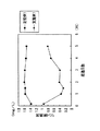
そして、1.6mg/Lのリン酸水溶液を毎時2.2リットルで給水管から導入し、カラム内を経て排水管まで到達した脱リン材(実施例1)で処理された水溶液のリン酸濃度をリン酸濃度測定装置で測定した。このリン酸濃度の測定は、リン酸水溶液を給水管から導入して45分後、1日後、1.5日後、2日後、3日後、4日後、5日後にそれぞれ行った。その結果を図1に示す。
【0036】
(脱リン性能評価実験2)
また、脱リン材(実施例1)の脱リン性能を評価するために、以下に記すような実験(脱リン性能評価実験2)も行った。
【0037】
まず、100mlの三角フラスコに脱リン材(実施例1)を20g投入した後、その三角フラスコ内に1.5mg/Lのリン酸水溶液を60ml加えて15分間保持した。15分経過後、リン酸水溶液中に浸漬された脱リン材(実施例1)を三角フラスコから取り出して、三角フラスコ内に残存するリン酸水溶液のリン酸濃度を測定した。
【0038】
次に、三角フラスコから取り出した脱リン材(実施例1)を新たな100mlの三角フラスコに投入し、その三角フラスコ内に1.6mg/Lのリン酸水溶液を60ml加えて15分間保持した。15分経過後、リン酸水溶液中に浸漬された脱リン材(実施例1)を三角フラスコから取り出して、三角フラスコ内に残存するリン酸水溶液のリン酸濃度を測定した。
【0039】
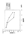
そして、この操作を繰り返して行い、脱リン材(実施例1)がリン酸水溶液に浸漬された累積時間が40分間、60分間となった後のリン酸水溶液のリン酸濃度をそれぞれ測定した。その結果を図2に示す。
【0040】
(脱リン性能評価実験3)
更に、脱リン材(実施例1)の脱リン性能を評価するために、以下に記すような実験(脱リン性能評価実験3)も行った。
【0041】
まず、1Lの三角フラスコに脱リン材(実施例1)を100g投入した後、その三角フラスコ内に4.3mg/Lのリン酸二水素カリウム(第1リン酸カリウム)水溶液を1L加えた。なお、脱リン材で処理する前のリン酸二水素カリウム水溶液のリン酸濃度は、3.28mg/Lであった。そして、振とう機を用いて100rpmで三角フラスコを振とうし、1時間後、3時間後、5時間後、7時間後における三角フラスコ内の水溶液のリン酸濃度をそれぞれ測定した。その結果を図3に示す。
【0042】
(実施例2)
実施例2では、実施例1の使用済み脱硫剤に代えて、粒状物からなる消石灰を用いた。そして、実施例1の脱リン材の製造方法に準じて、粒径3〜5mmの多孔質体からなる脱リン材(実施例2)を得た。本実施例の脱リン材は、表1に示す成分組成となっている。また、粉末X線回折により、実施例2の脱リン材に酸化カルシウムが含有していることを確認した。この脱リン材(実施例2)の脱リン性能に係る評価実験として、実施例1の脱リン性能評価実験2に準じて行った。その結果を図2に示す。
【0043】
(比較例1)
比較例1では、実施例1の集塵ダスト94重量%と、水6重量%とを用意した。そして、集塵ダストに水を適宜加えながら混練して混練物とした。その後の製造方法は、実施例1の脱リン材の製造方法に準じ、粒径3〜5mmの多孔質体からなる脱リン材(比較例1)を得た。比較例の脱リン材は、表1に示す成分組成となっている。この脱リン材(比較例1)の脱リン性能に係る評価実験として、実施例1の脱リン性能評価実験1及び脱リン性能評価実験2に準じて行った。その結果を図1及び図2に示す。
【0044】
(比較例2)
比較例2では、脱リン材として、従来技術に係る凝集剤としての消石灰をそのまま用いた。この脱リン材(比較例2)の脱リン性能に係る評価実験として、実施例1の脱リン性能評価実験3に準じて行った。その結果を図3に示す。
【0045】
(脱リン材の評価)
図1及び図2に示されるように、実施例1の脱リン材は、比較例1の脱リン材よりも脱リン性能に優れていることがわかる。また、図2から理解できるように、実施例1の脱リン材と実施例2の脱リン材とを比較した場合、両者の脱リン性能に差異は、ほとんど見られない。換言すれば、脱リン材に供される水酸化カルシウムとして、鋳物工場から廃出された使用済みの脱硫剤を用いた場合でも、水酸化カルシウム成分のみからなるものを用いた場合により得られる脱リン材と同等の脱リン性能を発揮することが可能であることがわかった。これにより、使用済みの脱硫剤を有効利用できることが確認できた。また、実施例1及び実施例2の脱リン材に供される集塵ダストも有効利用できることがわかった。
【0046】
図3に示されるように、実施例1の脱リン材は、比較例2の脱リン材よりも脱リン性能に優れていることがわかる。図3に係る評価実験において、評価実験後の実施例1に係る三角フラスコ内では、脱リン材にのみスラッジが付着しているのが観察され、三角フラスコから脱リン材を取り除くことでスラッジも一緒に取り除くことができるということを確認できた。一方、評価実験後の比較例2に係る三角フラスコ内では、内壁面にスラッジが付着していたり、底部にスラッジが沈殿していたり、スラッジが浮遊していたり等するのが観察され、スラッジの除去作業が容易でないことを確認できた。
【0047】
他に、特許請求の範囲の各請求項に記載されないものであって、前記実施の形態及び前記実施例等から把握される技術的思想について、以下にその効果と共に記載する。
【0048】
(a) 請求項1又は請求項2に記載の脱リン材において、前記無機材料は、72〜76重量%、前記水酸化カルシウムは、20〜22重量%、前記水は、4〜8重量%であることを特徴とする脱リン材。
【0049】
上記(a)によれば、請求項1,請求項2に記載の発明の効果を奏する。
【0050】
(b) シリカ及びアルミナを含有する無機材料72〜76重量%と水酸化カルシウム20〜22重量%と水4〜8重量%とを準備する準備工程と、
前記準備工程で準備した前記無機材料と前記水酸化カルシウムと前記水とを混練して混練物とする混練工程と、
前記混練物を粒径2〜10mmとなるように造粒して造粒物とする造粒工程と、
前記造粒物を600〜1000℃で焼成する焼成工程と
を備えたことを特徴とする脱リン材の製造方法。
【0051】
上記(b)によれば、請求項2に記載の発明の脱リン材と同様の効果を奏する多孔質体からなる脱リン材を製造することができる。
【0052】
(c) 請求項4又は上記(b)の脱リン材の製造方法において、前記無機材料として、鋳物工場から廃出された鋳物廃砂又は集塵ダストを用い、前記水酸化カルシウムとして、鋳物工場における溶湯の脱硫時に使用された石灰石を主成分とする脱硫剤を用いることを特徴とする脱リン材の製造方法。
【0053】
上記(c)によれば、請求項4,上記(b)に記載の効果に加えて、鋳物工場から発生する廃棄物を用いることができるため、廃棄物の有効利用を図ることができるようになる。また、廃棄物を有効利用することで、脱リン材を安価に製造することもできる。
【0054】
【発明の効果】
請求項1,請求項2に記載の発明によれば、水中のリンをスラッジに変え、該スラッジを脱リン材の表面や孔内面に付着させることにより、スラッジの除去を容易に行うことができる。すなわち、スラッジの除去作業を行う場合、従来技術の場合とは異なり、水中から脱リン材を取り除くだけでスラッジも一緒に除去することができるため、スラッジの除去作業を容易に行うことが可能となる。従って、従来技術のように、生成したスラッジの沈殿が完了するまでに時間がかかって作業性が悪くなったり、スラッジが沈降せずに浮遊等したままの状態で残って処理し難くなったりするという問題が生じることはなくなる。
【0055】
また、請求項2に記載の発明によれば、脱リン材を所定粒径となるように容易に調整できるため、脱リン材を使用目的に応じた粒径とすることが可能となる。更に、請求項2に記載の発明によれば、脱リン材の取り扱いを簡便なものとすることができる。
【0056】
請求項3に記載の発明によれば、請求項1,請求項2に記載の発明の効果に加えて、無機材料及び水酸化カルシウムとして、鋳物工場から発生する廃棄物を用いることができるため、廃棄物の有効利用を図ることができるようになる。また、廃棄物を有効利用することで、脱リン材を安価に製造することもできる。
【0057】
請求項4に記載の発明によれば、請求項1に記載の発明の脱リン材と同様の効果を奏する多孔質体からなる脱リン材を製造することができる。
【図面の簡単な説明】
【図1】実施例1及び比較例1の脱リン性能に係るリン酸濃度を測定した結果を示すグラフである。
【図2】実施例1、実施例2及び比較例1の脱リン性能に係るリン酸濃度を測定した結果を示すグラフである。
【図3】実施例1及び比較例2の脱リン性能に係るリン酸濃度を測定した結果を示すグラフである。[0001]
TECHNICAL FIELD OF THE INVENTION
The present invention relates to a dephosphorizing material used for removing phosphoric acid and phosphate (hereinafter, simply referred to as “phosphorus”) present in wastewater such as sewage and human waste, and water such as rivers and lakes. It relates to the manufacturing method.
[0002]
[Prior art]
In recent years, environmental conservation and securing of water resources have become very important social issues, and the technical content and range required for water treatment are tending to become more sophisticated and diversified. Phosphorus is known as a causative substance that causes the eutrophication phenomenon of water quality, and there is a strong demand for removing this phosphorus from water.
[0003]
Therefore, conventionally, as a method for removing phosphorus in water, a coagulation sedimentation method is generally used (for example, see Non-Patent Document 1). In this coagulation sedimentation method, a coagulant such as lime, iron, and aluminum is added to water containing phosphorus to generate a poorly soluble phosphorus compound (hereinafter, referred to as “sludge”), and the sludge is precipitated. This is to remove phosphorus.
[0004]
[Non-patent document 1]
Koji Yamamoto, "Nitrogen / phosphorus removal treatment in human waste septic tank", Environmental Technology, 1982, Vol. 11, No. 11, p. 843
[0005]
[Problems to be solved by the invention]
However, in the above-described coagulation-sedimentation method according to the related art, a large amount of coagulant is required, so that the amount of generated sludge increases, and the generated sludge has poor sedimentation properties. There's a problem.
[0006]
The present invention has been made in view of the above-mentioned circumstances, and an object of the present invention is to provide a dephosphorizing material capable of converting phosphorus in water into sludge and removing the sludge easily, and a method for producing the same. It is in.
[0007]
[Means for Solving the Problems]
The present inventors have conducted intensive studies to achieve the above-mentioned object, and as a result, by attaching sludge to the surface of the phosphorus removing material made of a porous body and the inner surface of the hole, the sludge can be easily removed. And found that the present invention was completed. The gist of the dephosphorizing material of the invention according to claim 1 is that an inorganic material containing silica and alumina, calcium hydroxide and water are kneaded, and the kneaded material is fired to form a porous body. .
[0008]
According to the first aspect of the present invention, when the dephosphorizing material is placed in water containing phosphorus, the phosphorus in contact with the dephosphorizing material changes into a poorly soluble sludge, and the sludge is converted from a porous material. It adheres to the surface of the dephosphorizing material or adheres to the inner surfaces of a plurality of holes, and is hardly released into water.
[0009]
The dephosphorizing material of the invention according to claim 2 is the same as the invention according to claim 1, except that the kneaded material is granulated to obtain a granulated product. By doing so, it becomes easy to adjust the dephosphorizing material obtained after firing the granulated product to have a predetermined particle size. This allows the dephosphorizing material to have a particle size according to the purpose of use. Further, since the dephosphorizing material has a uniform particle size, handling of the dephosphorizing material becomes simple.
[0010]
According to a third aspect of the present invention, there is provided the dephosphorizing material according to the first or second aspect, wherein, as the inorganic material, casting waste sand or dust collected from a foundry is used as the inorganic material; The gist of the invention is to use a desulfurizing agent mainly composed of limestone used at the time of desulfurization of molten metal in a foundry.
[0011]
According to the third aspect of the present invention, in addition to the functions and effects of the first and second aspects of the present invention, waste generated from a foundry is used as the inorganic material and calcium hydroxide. Effective utilization of waste can be achieved, and disposal costs such as landfill of waste can be eliminated. In addition, by effectively utilizing waste, it becomes possible to manufacture a dephosphorized material at low cost.
[0012]
According to a fourth aspect of the present invention, there is provided a method for preparing a dephosphorizing material comprising preparing 70 to 82% by weight of an inorganic material containing silica and alumina, 15 to 27% by weight of calcium hydroxide, and 3 to 15% by weight of water. A kneading step of kneading the inorganic material prepared in the preparation step, the calcium hydroxide and the water to form a kneaded product, and a baking process of firing the kneaded product at 600 to 1000 ° C. That is the gist.
[0013]
Here, the reason why the amount of the inorganic material is set to 70 to 82% by weight is to obtain a dephosphorizing material that is hardly disintegrated in water. The reason why the content of calcium hydroxide is set to 15 to 27% by weight is that if the content of calcium hydroxide is less than 15% by weight, the phosphorus removal function as a phosphorus removal material may not be sufficiently exhibited. If the amount exceeds the above range, the strength of the dephosphorizing material may be insufficient and the material may collapse in water. The reason for setting the water content to 3 to 15% by weight is that if the water content is less than 3% by weight, it may be difficult to perform the kneading step, and if the water content exceeds 15% by weight, handling of the kneaded material may be difficult. This is because there is a possibility that it will be inconvenient.
[0014]
When the kneaded material is fired at 600 to 100 ° C., if the temperature is lower than 600 ° C., the strength of the dephosphorizing material after firing may be insufficient or a porous body may not be obtained after firing. If the temperature exceeds 1000 ° C., it is disadvantageous in terms of energy cost.
[0015]
According to the fourth aspect of the present invention, by performing the above-described preparation step, kneading step, and firing step, it is possible to obtain a dephosphorized material made of a porous body.
[0016]
BEST MODE FOR CARRYING OUT THE INVENTION
As the inorganic material provided for the dephosphorizing material, a material containing other components as long as it contains at least both silica (silicon dioxide) and alumina (aluminum oxide) may be used. Good. Here, as the inorganic material, it is possible to use dust collected dust discharged as dust waste from a dust collector of a foundry when casting cast iron, or foundry sand discharged as waste from a foundry. Dust collected dust and foundry waste sand contain iron oxide (3 to 10% by weight) in addition to silica (50 to 70% by weight) and alumina (5 to 20% by weight). As an example, when the component ratio of the collected dust is represented by a weight ratio, silica 61.2% by weight, alumina 19.5% by weight, iron oxide 4.97% by weight, calcium oxide 1.89% by weight, magnesium oxide 2. 49% by weight, and 9.95% by weight (including carbon etc.). In particular, since the dust dust has a particle size (1 to 300 μm), when it is kneaded together with calcium hydroxide and water, it is easy to knead them so that they are even. As a result, the resulting dephosphorized material is less likely to be biased, and can sufficiently exhibit its function as a dephosphorized material.
[0017]
As the calcium hydroxide to be provided to the dephosphorizing material, those composed of only a calcium hydroxide component or those partially containing a calcium hydroxide component can be used. As the calcium hydroxide, a desulfurizing agent mainly composed of limestone used at the time of desulfurizing a molten metal in a foundry, that is, a used desulfurizing agent (desulfurized slag) can be used. The present inventors have confirmed by powder X-ray diffraction that the used desulfurizing agent contains a calcium hydroxide component.
[0018]
The phosphorus removing material is made of a porous body having a plurality of pores, and is obtained by kneading the above-described inorganic material, calcium hydroxide, and water, and firing the kneaded material. Before firing the kneaded material, the kneaded material may be granulated to obtain a granulated material, and the granulated material may be fired to obtain a dephosphorized material. Here, when a used desulfurizing agent is used as calcium hydroxide, it is preferable that the desulfurizing agent is pulverized into powder or granules. The reason is that since the used desulfurizing agent is often in a lump, it is difficult to knead evenly with the inorganic material and water evenly. If they are not kneaded so as to be uniform, the resulting dephosphorized material may be biased, and the function as the dephosphorized material may not be sufficiently exhibited.
[0019]
The dephosphorizing material is preferably adjusted to have a predetermined particle size according to the purpose of use. Although the particle size of the dephosphorizing material is not particularly limited, it is preferably set to 1 to 10 mm, more preferably to 2 to 7 mm, and still more preferably to 3 to 5 mm.
[0020]
Phosphorus-removing materials contain calcium oxide, and when phosphorus in water comes into contact with the calcium component in the calcium oxide, the calcium component reacts with the phosphorus to form hardly soluble sludge. I have.
[0021]
Now, a method for producing the dephosphorizing material will be described in detail. First, a preparation step for preparing the inorganic material, the calcium hydroxide, and water is performed. In this case, the content is preferably 70 to 82% by weight of an inorganic material, 15 to 27% by weight of calcium hydroxide, and 3 to 15% by weight of water. More preferably, the content is 72 to 76% by weight of an inorganic material, 20 to 22% by weight of calcium hydroxide, and 4 to 8% by weight of water.
[0022]
Next, a kneading step of kneading the inorganic material, calcium hydroxide, and water prepared in the preparing step to obtain a kneaded product is performed. In this case, the inorganic material and calcium hydroxide are first mixed to form a mixture, then water may be added to the mixture and kneaded to form a kneaded product, or a mixture of the inorganic material and calcium hydroxide may be mixed. The mixture may be kneaded by appropriately kneading while adding water, or may be kneaded by simultaneously mixing and kneading the three materials. In particular, it is possible to obtain a kneaded product in an optimum state by adjusting and kneading the mixture while appropriately adding water.
[0023]
After the kneading step, a granulating step of granulating the kneaded product to obtain a granulated product may be performed, or a firing step described below may be performed with the granulating step omitted. When the granulating step is performed after the kneading step, it becomes easy to adjust the dephosphorizing material obtained after firing the granulated material to have a predetermined particle size. The particle size of the granulated material is not particularly limited, but is preferably set to 2 to 10 mm, more preferably 3 to 5 mm.
[0024]
Finally, a firing step of firing the kneaded material or the granulated material is performed. The firing temperature in the firing step is preferably from 600 to 1000C, more preferably from 700 to 900C, even more preferably from 750 to 850C. After the completion of the firing step, a dephosphorized material composed of a porous body is obtained.
[0025]
When the dephosphorized material obtained as described above is used for phosphorus removal, the dephosphorized material is installed in a flow path of sewage such as sewage or human waste, or the dephosphorized material is treated for sewage such as sewage or human waste. It can be used by installing it in a tank or installing the dephosphorizing material as it is in water. When phosphorus comes into contact with the dephosphorized material, the phosphorus is formed as a sparingly soluble sludge and removed from the water, and the generated sludge adheres to the dephosphorized material or adheres to the inner surface of the hole of the dephosphorized material. And so on.
[0026]
When installing the dephosphorizing material in the sewage treatment tank or as it is in water, it is necessary to put the dephosphorizing material in, for example, a container so that the dephosphorizing material can be collected together with the container. preferable. In this case, by simply lifting the container from the water, sludge can be collected at the same time as the phosphorus-removing material is collected. In addition, since the dephosphorized material to which sludge adheres is easily precipitated by the amount to which sludge adhered, the sludge is removed together with the dephosphorization material from the bottom of the sewage treatment tank without using a container. be able to.
[0027]
【Example】
Hereinafter, Examples 1 and 2 and Comparative Examples 1 and 2 that further embody the present invention will be described.
[0028]
(Example 1)
In Example 1, 76% by weight of dust collected, 19% by weight of a used desulfurizing agent, and 5% by weight of water were prepared. This dust consists of 63% by weight of silica, 12% by weight of alumina, 7% by weight of iron oxide and 18% by weight of the balance. The used desulfurizing agent contains 83.2% by weight of calcium hydroxide, and after being pulverized, sieved to form granules having a particle size of 1.4 mm or less.
[0029]
Then, 80 parts by weight of the collected dust was mixed with 20 parts by weight of the used desulfurizing agent to form a mixture, and the mixture was kneaded while appropriately adding water to obtain a kneaded product. Thereafter, the kneaded product was granulated by a stirring granulator to obtain a granulated product having an average particle size of 4 mm.
[0030]
Next, the obtained granules were fired at a temperature of 800 ° C. for 4 hours to obtain a fired body. The fired body was sieved to obtain a phosphorus-removing material (Example 1) composed of a porous body having a particle size of 3 to 5 mm. The phosphorus removal material of this example has the component composition shown in Table 1. Further, it was confirmed by powder X-ray diffraction that the dephosphorizing material of Example 1 contained calcium oxide.
[0031]
[Table 1]
[0032]
(Dephosphorization performance evaluation experiment 1)
In order to evaluate the dephosphorization performance of the dephosphorization material (Example 1), the following experiment (dephosphorization performance evaluation experiment 1) was performed.
[0033]
First, a column having an inner diameter of 5 cm and a height of 75 cm is installed so as to extend in the vertical direction, a wire mesh is arranged inside the center portion of the column along the horizontal direction, and a dephosphorizing material (Example) is provided on the wire mesh. 450 g of 1) was placed. The mesh of the wire mesh is set to be smaller than 3 mm, and the dephosphorizing material (Example 1) does not fall off the wire mesh.
[0034]
Next, a water supply pipe is connected to the upper end of the column, and a drain pipe is connected to the lower end of the column. A phosphoric acid concentration measuring device for measuring the phosphoric acid concentration of the aqueous solution is connected to the drain pipe, and the measuring device measures the phosphoric acid concentration of the aqueous solution treated with the dephosphorizing material (Example 1). It is supposed to be.
[0035]
Then, a 1.6 mg / L phosphoric acid aqueous solution was introduced at 2.2 liters / hour from the water supply pipe, and the phosphoric acid concentration of the aqueous solution treated with the dephosphorizing material (Example 1) which reached the drain pipe through the column was reached. Was measured with a phosphoric acid concentration measuring device. The measurement of the phosphoric acid concentration was performed 45 minutes, 1 day, 1.5 days, 2 days, 3 days, 4 days, and 5 days after the phosphoric acid aqueous solution was introduced from the water supply pipe. The result is shown in FIG.
[0036]
(Dephosphorization performance evaluation experiment 2)
In addition, in order to evaluate the dephosphorization performance of the dephosphorizing material (Example 1), the following experiment (dephosphorization performance evaluation experiment 2) was also performed.
[0037]
First, 20 g of a dephosphorizing material (Example 1) was charged into a 100 ml Erlenmeyer flask, and then 60 ml of a 1.5 mg / L phosphoric acid aqueous solution was added to the Erlenmeyer flask and held for 15 minutes. After a lapse of 15 minutes, the phosphorus removing material (Example 1) immersed in the aqueous phosphoric acid solution was taken out of the Erlenmeyer flask, and the phosphoric acid concentration of the aqueous phosphoric acid solution remaining in the Erlenmeyer flask was measured.
[0038]
Next, the dephosphorizing material (Example 1) taken out of the Erlenmeyer flask was charged into a new 100 ml Erlenmeyer flask, and 60 ml of a 1.6 mg / L phosphoric acid aqueous solution was added to the Erlenmeyer flask and held for 15 minutes. After a lapse of 15 minutes, the phosphorus removing material (Example 1) immersed in the aqueous phosphoric acid solution was taken out of the Erlenmeyer flask, and the phosphoric acid concentration of the aqueous phosphoric acid solution remaining in the Erlenmeyer flask was measured.
[0039]
This operation was repeated to measure the phosphoric acid concentration of the phosphoric acid aqueous solution after the accumulated time during which the dephosphorizing material (Example 1) was immersed in the aqueous phosphoric acid solution was 40 minutes and 60 minutes, respectively. The result is shown in FIG.
[0040]
(Dephosphorization performance evaluation experiment 3)
Further, in order to evaluate the dephosphorization performance of the dephosphorizing material (Example 1), the following experiment (dephosphorization performance evaluation experiment 3) was also performed.
[0041]
First, 100 g of a dephosphorizing material (Example 1) was charged into a 1 L Erlenmeyer flask, and then 1 L of a 4.3 mg / L potassium dihydrogen phosphate (monobasic potassium phosphate) aqueous solution was added to the Erlenmeyer flask. The phosphoric acid concentration of the aqueous solution of potassium dihydrogen phosphate before the treatment with the dephosphorizing material was 3.28 mg / L. Then, the Erlenmeyer flask was shaken at 100 rpm using a shaker, and the phosphoric acid concentration of the aqueous solution in the Erlenmeyer flask was measured after 1 hour, 3 hours, 5 hours, and 7 hours. The result is shown in FIG.
[0042]
(Example 2)
In Example 2, slaked lime composed of granular material was used in place of the used desulfurizing agent of Example 1. And according to the manufacturing method of the phosphorus removal material of Example 1, the phosphorus removal material (Example 2) which consists of a porous body with a particle diameter of 3-5 mm was obtained. The phosphorus removal material of this example has the component composition shown in Table 1. Further, it was confirmed by powder X-ray diffraction that the phosphorus removal material of Example 2 contained calcium oxide. As an evaluation experiment relating to the dephosphorization performance of the dephosphorizing material (Example 2), it was performed in accordance with the dephosphorization performance evaluation experiment 2 of Example 1. The result is shown in FIG.
[0043]
(Comparative Example 1)
In Comparative Example 1, 94% by weight of the dust collected in Example 1 and 6% by weight of water were prepared. And it knead | mixed, adding water appropriately to dust collection dust, and obtained the kneaded material. The subsequent manufacturing method was the same as the method for manufacturing a dephosphorized material of Example 1 to obtain a dephosphorized material (Comparative Example 1) composed of a porous body having a particle size of 3 to 5 mm. The phosphorus removal material of the comparative example has the component composition shown in Table 1. As an evaluation experiment relating to the dephosphorization performance of the dephosphorization material (Comparative Example 1), the evaluation was performed in accordance with the dephosphorization performance evaluation experiment 1 and the dephosphorization performance evaluation experiment 2 of Example 1. The results are shown in FIGS.
[0044]
(Comparative Example 2)
In Comparative Example 2, slaked lime as a coagulant according to the prior art was used as it was as a dephosphorizing material. As an evaluation experiment relating to the dephosphorization performance of the dephosphorization material (Comparative Example 2), the evaluation was performed in accordance with the dephosphorization performance evaluation experiment 3 of Example 1. The result is shown in FIG.
[0045]
(Evaluation of phosphorus removal material)
As shown in FIGS. 1 and 2, it can be seen that the dephosphorizing material of Example 1 is more excellent in dephosphorizing performance than the dephosphorizing material of Comparative Example 1. Further, as can be understood from FIG. 2, when comparing the dephosphorizing material of Example 1 and the dephosphorizing material of Example 2, there is almost no difference in the dephosphorizing performance between the two. In other words, even when a used desulfurizing agent discharged from a foundry is used as the calcium hydroxide to be supplied to the dephosphorizing material, a dehydration obtained by using only a calcium hydroxide component is used. It was found that it was possible to exhibit the same dephosphorization performance as the phosphorus material. As a result, it was confirmed that the used desulfurizing agent can be effectively used. Further, it was found that the dust collected in the dephosphorizing materials of Example 1 and Example 2 can be effectively used.
[0046]
As shown in FIG. 3, it can be seen that the dephosphorizing material of Example 1 is more excellent in dephosphorizing performance than the dephosphorizing material of Comparative Example 2. In the evaluation experiment according to FIG. 3, in the Erlenmeyer flask according to Example 1 after the evaluation experiment, it was observed that sludge only adhered to the dephosphorizing material, and the sludge was removed by removing the dephosphorizing material from the Erlenmeyer flask. I was able to confirm that they could be removed together. On the other hand, in the Erlenmeyer flask according to Comparative Example 2 after the evaluation experiment, it was observed that sludge was attached to the inner wall surface, sludge was settled at the bottom, sludge was floating, and the like. It was confirmed that the removal operation was not easy.
[0047]
In addition, technical ideas that are not described in each claim of the claims and that are grasped from the embodiment, the example, and the like are described below together with their effects.
[0048]
(A) In the dephosphorizing material according to claim 1 or 2, the inorganic material is 72 to 76% by weight, the calcium hydroxide is 20 to 22% by weight, and the water is 4 to 8% by weight. A dephosphorizing material, characterized in that:
[0049]
According to the above (a), the effects of the first and second aspects of the invention are achieved.
[0050]
(B) a preparation step of preparing 72 to 76% by weight of an inorganic material containing silica and alumina, 20 to 22% by weight of calcium hydroxide, and 4 to 8% by weight of water;
A kneading step of kneading the inorganic material, the calcium hydroxide, and the water prepared in the preparing step to form a kneaded product,
A granulating step of granulating the kneaded product to a particle size of 2 to 10 mm to form a granulated product;
And baking the granulated material at a temperature of 600 to 1000 ° C.
[0051]
According to the above (b), it is possible to manufacture a dephosphorizing material made of a porous body having the same effect as the dephosphorizing material according to the second aspect of the present invention.
[0052]
(C) In the method for producing a dephosphorized material according to claim 4 or (b), as the inorganic material, foundry waste sand or dust collected from a foundry is used, and as the calcium hydroxide, a foundry is used. A method for producing a dephosphorized material, characterized by using a desulfurizing agent containing limestone as a main component used in desulfurizing a molten metal in the method.
[0053]
According to (c), in addition to the effects described in claim 4 and (b), waste generated from a foundry can be used, so that effective use of waste can be achieved. Become. Further, by effectively utilizing the waste, the phosphorus removal material can be manufactured at low cost.
[0054]
【The invention's effect】
According to the first and second aspects of the present invention, sludge can be easily removed by changing phosphorus in water to sludge and attaching the sludge to the surface of the phosphorus-free material or the inner surface of the hole. . In other words, when performing the sludge removal work, unlike the prior art, sludge can be removed together with water only by removing the dephosphorizing material from the water, so that the sludge removal work can be easily performed. Become. Therefore, as in the prior art, it takes time to complete the settling of the generated sludge, resulting in poor workability, or the sludge remains in a floating state without being settled and becomes difficult to treat. The problem will not occur.
[0055]
According to the second aspect of the present invention, since the dephosphorizing material can be easily adjusted to have a predetermined particle size, the particle size of the dephosphorizing material can be adjusted according to the purpose of use. Furthermore, according to the second aspect of the invention, the handling of the dephosphorizing material can be simplified.
[0056]
According to the third aspect of the present invention, in addition to the effects of the first and second aspects of the present invention, waste generated from a foundry can be used as the inorganic material and calcium hydroxide. Effective use of waste can be achieved. Further, by effectively utilizing the waste, the phosphorus removal material can be manufactured at low cost.
[0057]
According to the fourth aspect of the present invention, it is possible to produce a dephosphorizing material made of a porous body having the same effect as the dephosphorizing material of the first aspect.
[Brief description of the drawings]
FIG. 1 is a graph showing the results of measuring the phosphoric acid concentration relating to the dephosphorization performance of Example 1 and Comparative Example 1.
FIG. 2 is a graph showing the results of measuring the phosphoric acid concentration relating to the dephosphorization performance of Example 1, Example 2, and Comparative Example 1.
FIG. 3 is a graph showing the results of measuring the phosphoric acid concentration relating to the dephosphorization performance of Example 1 and Comparative Example 2.