JP2004122002A - Self-traveling type recycled article production machine, information processing device and information display device used for the same - Google Patents
Self-traveling type recycled article production machine, information processing device and information display device used for the same Download PDFInfo
- Publication number
- JP2004122002A JP2004122002A JP2002290664A JP2002290664A JP2004122002A JP 2004122002 A JP2004122002 A JP 2004122002A JP 2002290664 A JP2002290664 A JP 2002290664A JP 2002290664 A JP2002290664 A JP 2002290664A JP 2004122002 A JP2004122002 A JP 2004122002A
- Authority
- JP
- Japan
- Prior art keywords
- information data
- self
- pressure
- display
- propelled
- Prior art date
- Legal status (The legal status is an assumption and is not a legal conclusion. Google has not performed a legal analysis and makes no representation as to the accuracy of the status listed.)
- Pending
Links
- 238000004519 manufacturing process Methods 0.000 title claims abstract description 72
- 230000010365 information processing Effects 0.000 title claims description 30
- 238000001514 detection method Methods 0.000 claims abstract description 113
- 238000012545 processing Methods 0.000 claims abstract description 42
- 239000000463 material Substances 0.000 claims description 22
- 238000000034 method Methods 0.000 claims description 14
- 238000004064 recycling Methods 0.000 claims description 14
- 230000008569 process Effects 0.000 claims description 12
- 230000004044 response Effects 0.000 claims description 7
- 230000005856 abnormality Effects 0.000 abstract description 30
- 239000004973 liquid crystal related substance Substances 0.000 abstract description 16
- 230000002159 abnormal effect Effects 0.000 abstract description 5
- 230000010485 coping Effects 0.000 abstract 1
- 239000006148 magnetic separator Substances 0.000 description 58
- 239000000047 product Substances 0.000 description 57
- 239000003921 oil Substances 0.000 description 37
- 239000000446 fuel Substances 0.000 description 22
- 239000013642 negative control Substances 0.000 description 20
- XLYOFNOQVPJJNP-UHFFFAOYSA-N water Substances O XLYOFNOQVPJJNP-UHFFFAOYSA-N 0.000 description 16
- 239000010720 hydraulic oil Substances 0.000 description 13
- 238000002347 injection Methods 0.000 description 12
- 239000007924 injection Substances 0.000 description 12
- 239000002689 soil Substances 0.000 description 12
- 230000007423 decrease Effects 0.000 description 11
- 238000002156 mixing Methods 0.000 description 11
- 230000007935 neutral effect Effects 0.000 description 11
- 238000004891 communication Methods 0.000 description 9
- 238000010586 diagram Methods 0.000 description 9
- 230000008859 change Effects 0.000 description 7
- 230000006872 improvement Effects 0.000 description 7
- 239000002023 wood Substances 0.000 description 7
- 239000004576 sand Substances 0.000 description 6
- 238000011144 upstream manufacturing Methods 0.000 description 6
- 238000010276 construction Methods 0.000 description 5
- 230000002950 deficient Effects 0.000 description 5
- 230000000694 effects Effects 0.000 description 5
- 239000000203 mixture Substances 0.000 description 5
- 239000002699 waste material Substances 0.000 description 5
- 244000126211 Hericium coralloides Species 0.000 description 4
- 230000007246 mechanism Effects 0.000 description 4
- 238000004364 calculation method Methods 0.000 description 3
- 239000000498 cooling water Substances 0.000 description 3
- 238000006073 displacement reaction Methods 0.000 description 3
- 239000002828 fuel tank Substances 0.000 description 3
- 238000003825 pressing Methods 0.000 description 3
- 239000011435 rock Substances 0.000 description 3
- 239000011265 semifinished product Substances 0.000 description 3
- 239000003516 soil conditioner Substances 0.000 description 3
- 238000003756 stirring Methods 0.000 description 3
- 239000010426 asphalt Substances 0.000 description 2
- 238000007599 discharging Methods 0.000 description 2
- 238000005516 engineering process Methods 0.000 description 2
- 239000010419 fine particle Substances 0.000 description 2
- 239000002440 industrial waste Substances 0.000 description 2
- 230000033001 locomotion Effects 0.000 description 2
- 238000012423 maintenance Methods 0.000 description 2
- 239000002184 metal Substances 0.000 description 2
- 230000003014 reinforcing effect Effects 0.000 description 2
- 230000008439 repair process Effects 0.000 description 2
- 239000010865 sewage Substances 0.000 description 2
- 238000013024 troubleshooting Methods 0.000 description 2
- 230000009471 action Effects 0.000 description 1
- 230000003213 activating effect Effects 0.000 description 1
- 230000005540 biological transmission Effects 0.000 description 1
- 238000006243 chemical reaction Methods 0.000 description 1
- 238000004140 cleaning Methods 0.000 description 1
- 238000007796 conventional method Methods 0.000 description 1
- 230000001186 cumulative effect Effects 0.000 description 1
- 239000000428 dust Substances 0.000 description 1
- 239000000945 filler Substances 0.000 description 1
- 239000007788 liquid Substances 0.000 description 1
- 239000000696 magnetic material Substances 0.000 description 1
- 238000005065 mining Methods 0.000 description 1
- 239000002245 particle Substances 0.000 description 1
- 239000002994 raw material Substances 0.000 description 1
- 239000013049 sediment Substances 0.000 description 1
- 238000010008 shearing Methods 0.000 description 1
Images


Landscapes
- Component Parts Of Construction Machinery (AREA)
- Disintegrating Or Milling (AREA)
Abstract
Description
【0001】
【発明の属する技術分野】
本発明は、被破砕物を破砕する破砕装置を備えた自走式破砕機や、土砂に土質改良材を加えて混合する混合装置を備えた自走式土質改良機等を含む自走式リサイクル品生産機及びこれに用いる情報処理装置並びに情報表示装置に関するものである。
【0002】
【従来の技術】
近年の廃棄物再利用促進の背景の下、自走式破砕機や自走式土質改良機といった自走式リサイクル品生産機の活躍の場が拡がりつつある。
【0003】
自走式破砕機は、例えばビル解体時に搬出されるコンクリート塊や道路補修時に排出されるアスファルト塊などの建設現場で発生する大小さまざまな岩石・建設廃材、あるいは産業廃棄物等(以下適宜、被破砕物という)をリサイクル原料とするものであり、例えば油圧ショベル等によって自走式破砕機上部の受け入れ手段としてのホッパに投入された被破砕物を、例えばホッパ下方に設けたフィーダによって処理装置としての破砕装置へ導き、この破砕装置で所定の大きさに破砕処理する。破砕物は、破砕装置下部の空間から破砕装置下方の排出コンベア上に落下し、この排出コンベアで運搬される。この運搬の途中で、排出コンベア上方に配置された磁選機によって例えばコンクリート塊に混入している鉄筋片等を吸着して取り除き、リサイクル用の破砕物製品又は半製品(以下、「リサイクル品」のように称する)として搬出するようになっている。
【0004】
一方、自走式土質改良機は、例えば、ガス管等の埋設工事、上下水道工事、及びその他の道路工事・基礎工事等において発生する建設発生土のうち埋め戻しに適さないものをリサイクル原料とするものであり、例えば油圧ショベル等によって自走式土質改良機上部の受け入れ手段としての土砂ホッパに投入された前記リサイクル原料(土砂)を例えば土砂ホッパ下方に設けた導入コンベアによって処理装置としての混合装置へ導き、この混合装置で土質改良材とともに混合処理し、混合物を排出コンベア上に落下させ、この排出コンベアでリサイクル用の土砂製品又は半製品(=リサイクル品)として自走式土質改良機から搬出するようになっている。
【0005】
なお、上記混合装置としては、複数の回転軸に多数の攪拌翼(パドル)を設けた攪拌手段(パドルミキサ)で、土砂及び土質改良材を導入側から排出側へと徐々に移送しつつ攪拌混合するいわゆるミキシング方式の混合装置や、回転軸まわりに回転する複数の回転打撃子を備え、土砂と土質改良材とを高所にて回転カッタで予解砕後自重で落下させ、その落下途中で前記回転打撃子で打撃を加えて土塊を細かく解砕し土質改良材と混合させるいわゆる解砕方式の混合装置等がある。
これら自走式リサイクル品生産機は、リサイクル処理を行う処理装置として、例えば上記の破砕装置や混合装置を備えており、これらは、無限軌道履帯、フィーダ、導入コンベア、排出コンベア、及び磁選機等と共に油圧駆動のアクチュエータ(この場合は破砕装置用油圧モータや混合装置用油圧モータ等の処理装置用油圧モータ)によって駆動動作される。すなわち、原動機(エンジン)によって少なくとも1つの油圧ポンプを駆動し、その油圧ポンプから吐出された圧油を処理装置用油圧モータに供給して駆動する。そしてこのとき、処理装置用油圧モータへ供給する圧油の例えば方向及び流量を処理装置用制御弁手段によって制御するようになっている。
【0006】
このとき、上記処理装置、フィーダ、排出コンベア、磁選機等の各機器や上記エンジンに係わる状態量を各種センサによって検出し、その検出値に基づく情報のうち通常作業時に有用な一部情報を運転席の操作者に表示するようにしたものがある(例えば、特許文献1参照)。
【0007】
この従来技術では、自走式リサイクル品生産機の一例である自走式破砕機において、操作者の搭乗する運転席の側方に配置した制御盤に計器盤部を設け、この計器盤部にて、エンジンの冷却水(ラジエータ水)の水温計と、エンジンの燃料計と、エンジンの稼働時間を表すアワメータとを表示するようにしている。
【0008】
【特許文献1】
特開2000−325823号公報
【0009】
【発明が解決しようとする課題】
上記従来技術では、上述したように、処理装置、フィーダ、排出コンベア、磁選機等の各機器やエンジンに係わる上記状態量を各種センサによって検出するものの、運転席の操作者に表示するのは、各種検出値に基づく情報のうち、エンジン冷却水温、エンジン燃料残量と、エンジン稼働時間のみとなっている。
【0010】
したがって、何らかの理由で稼働中にいずれかの機器やエンジン等が故障した場合、上記表示情報だけからではその異常発生箇所の特定及びその異常発生原因を特定することは困難である。このため、上記従来技術の公報には明確には記載されていないが、現実には、このような場合、操作者からの故障発生の報を受けたメンテナンス作業員(サービスマン)が情報取得・表示用の外部接続機器(例えばパソコン)を携えて当該機械のもとへ赴き、制御盤にその外部接続機器を接続して、各種センサによって検出された処理装置、フィーダ、排出コンベア、磁選機等の各機器やエンジンに係わる上記状態量データを取得して表示させ、これによって異常発生箇所の特定及びその異常発生原因を特定しなければならない。
【0011】
以上説明したように、上記従来技術では、故障時において、異常発生箇所の特定及びその異常発生原因を特定するためには、必ず外部接続機器を用意しこれを接続しなければならなかったため、迅速かつ容易な故障時対応という面において改善の余地があった。
【0012】
本発明の目的は、故障時において、外部接続機器を用いることなく、迅速かつ容易に異常発生箇所及び異常発生原因を特定できる自走式リサイクル品生産機及びこれに用いる情報処理装置並びに情報表示装置を提供することにある。
【0013】
【課題を解決するための手段】
(1)上記目的を達成するために、本発明の自走式リサイクル品生産機は、機械稼働に係わる各機器の状態量を検出する複数の検出手段と、前記検出手段の検出信号に基づき、通常作業用の第1情報データ及び故障時対応用の第2情報データを生成し、その生成したデータ信号を出力する処理を行う情報処理手段と、この情報処理手段から出力された前記第1情報データ又は前記第2情報データを選択的に表示する表示手段とを備える。
【0014】
本発明においては、検出手段の検出値に基づき、情報処理手段が、例えば原動機の稼働時間、油圧アクチュエータの作動油温等の通常作業用の第1情報データ、または、例えば油圧ポンプの吐出圧、油圧アクチュエータの負荷圧、処理装置・補助機械の実際の動作速度、原動機の回転数指示値、処理装置・補助機械の動作速度指示値等の故障時対応用の第2情報データを算出して出力し、表示手段が、それら第1情報データ若しくは第2情報データを選択的に表示する。
【0015】
これにより、通常作業中は、従来構造と同様に、表示手段に上記原動機稼働時間等の第1情報データを表示させておく一方で、故障発生時には、表示手段に各機器や原動機の詳細情報としての上記油圧ポンプ吐出圧等の第2情報データを表示させることができる。したがって、故障発生時には、多数の第2情報データを順次表示させてチェックしていき、例えば信号の流れ上どこまでが正常値でどこからが異常値であるかを判定することによって、どこで異常が発生しているか、及びその異常の原因が何であるかを特定することができる。この結果、従来構造のように外部接続機器を用いることなく、迅速かつ容易に異常発生箇所及び異常発生原因を特定することができる。
【0016】
(2)上記(1)において、好ましくは、前記情報処理手段は、前記第1情報データと前記第2情報データのいずれを表示するかを選択する第1選択手段の選択状況に応じて、前記第1情報データ又は前記第2情報データのいずれか一方のデータ信号を出力する。
【0017】
このように情報処理手段で既に第1情報データ若しくは第2情報データのいずれかに選択したものを表示手段に出力することにより、情報処理手段から表示手段までの通信データ量を低減することができ、情報処理手段側の通信負荷を低減することができる。
【0018】
(3)上記(1)において、また好ましくは、前記情報処理手段は、前記第1情報データと前記第2情報データの双方のデータ信号を出力するとともに、前記表示手段は、前記第1情報データと前記第2情報データのいずれを表示するかを選択する第2選択手段の選択状況に応じて、前記第1情報データ又は前記第2情報データのいずれか一方のデータを表示する。
【0019】
このように情報処理手段からは第1情報データと第2情報データの両方を表示手段に出力し、表示手段側でそれらのうちいずれかを選択して表示することにより、情報処理手段において情報データの識別及び選別処理を行う必要がなくなり、情報処理手段側の演算処理負荷を低減することができる。
【0020】
(4)上記(2)又は(3)において、さらに好ましくは、リサイクル原料に対し所定のリサイクル処理を行う処理装置と、この処理装置による前記リサイクル処理作業に関連する作業を行う補助機械と、原動機と、この原動機により駆動される油圧ポンプと、この油圧ポンプから吐出される圧油が供給され前記処理装置又は前記補助機械を駆動する油圧アクチュエータとを備え、前記表示手段は、前記故障時対応用データとして、前記検出手段で検出した、前記油圧ポンプの吐出圧、前記油圧アクチュエータの負荷圧、前記処理装置の実際の動作速度、及び前記補助機械の実際の動作速度のうち少なくとも一方を表示する。
【0021】
(5)上記(2)又は(3)において、また好ましくは、リサイクル原料に対し所定のリサイクル処理を行う処理装置と、この処理装置による前記リサイクル処理作業に関連する作業を行う補助機械と、原動機と、この原動機により駆動される油圧ポンプと、この油圧ポンプから吐出される圧油が供給され前記処理装置又は前記補助機械を駆動する油圧アクチュエータと、前記各機器の動作状態を設定する設定手段とを備え、前記表示手段は、前記故障時対応用データとして、前記設定手段で設定した、前記原動機の回転数、前記処理装置の動作速度、及び前記補助機械の動作速度のうち少なくとも1つを表示する。
【0022】
(6)上記目的を達成するために、また本発明は、機械稼働に係わる各機器の状態量を検出する複数の検出手段を備えた自走式リサイクル品生産機に設けられる自走式リサイクル品生産機の情報処理装置において、前記検出手段の検出信号を入力する入力手段と、この入力手段で入力した前記検出信号に基づき、通常作業用の第1情報データ又は故障時対応用の第2情報データを生成する第1生成手段と、前記自走式リサイクル製品生産機に設けた第1選択手段の選択状況に応じて、前記第1生成手段で生成した前記第1情報データ又は前記第2情報データのいずれか一方のデータを選択的に表示手段に切換出力する第1出力手段とを備える。
【0023】
(7)上記目的を達成するために、また本発明は、機械稼働に係わる各機器の状態量を検出する複数の検出手段を備えた自走式リサイクル品生産機に設けられる自走式リサイクル品生産機の情報処理装置において、前記検出手段の検出信号を入力する入力手段と、この入力手段で入力した前記検出信号に基づき、通常作業用の第1情報データと故障時対応用の第2情報データの双方のデータを生成する第2生成手段と、この第2生成手段で生成した前記第1情報データと前記第2情報データの双方のデータ信号を、いずれか一方を選択切換表示するための基礎情報として表示手段に出力する第2出力手段とを備える。
【0024】
(8)上記目的を達成するために、また本発明は、機械稼働に係わる各機器の状態量を検出する複数の検出手段を備えた自走式リサイクル品生産機に設けられる自走式リサイクル品生産機の情報表示装置において、前記検出手段の検出信号に基づき生成された、通常作業用の第1情報データ又は故障時対応用の第2情報データのいずれか一方のデータ信号を入力し、その入力した第1情報データ又は第2情報データのいずれか一方のデータを選択的に表示する。
【0025】
(9)上記目的を達成するために、また本発明は、機械稼働に係わる各機器の状態量を検出する複数の検出手段を備えた自走式リサイクル品生産機に設けられる自走式リサイクル品生産機の情報表示装置において、前記検出手段の検出信号に基づき生成された、通常作業用の第1情報データと故障時対応用の第2情報データの双方のデータを入力し、前記自走式リサイクル製品生産機に設けた第2選択手段の選択状況に応じて、その入力した第1情報データ又は第2情報データのいずれか一方のデータを選択的に切換表示する。
【0026】
【発明の実施の形態】
以下、本発明の自走式リサイクル品生産機の一実施の形態を図面を用いて説明する。
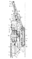
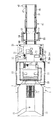
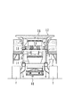
図1は、本発明の自走式リサイクル品生産機の一実施の形態の全体構造を表す側面図であり、図2はその上面図であり、図3は図1中左側から見た正面図である。これら図1乃至図3において、本実施の形態は、自走式リサイクル品生産機として、自走式破砕機を例にとった場合の実施の形態である。1は走行体で、この走行体1は、走行装置2と、この走行装置2の上部にほぼ水平に延設した本体フレーム3とで構成されている。また、4は走行装置2のトラックフレームで、このトラックフレーム4は、本体フレーム3の下部に連設している。5,6はそれぞれこのトラックフレーム4の両端に設けた従動輪(アイドラ)及び駆動輪、7はこれら従動輪5及び駆動輪6に巻回した履帯(無限軌道履帯)、8は駆動輪6に直結した走行用油圧モータであり、自走式破砕機の左側(図1中手前側、図2中下側)に配置された左走行用油圧モータ8L及び右側に配置された右走行用油圧モータ8R(図1中奥側、図2中上側)で構成されている(後述の図4参照)。9,10は本体フレーム3の長手方向一方側(図1中左側)に立設した支持ポスト、11はこれら支持ポスト9,10に支持された支持バーである。
【0027】
12は破砕対象となる被破砕物を受入れるホッパで、このホッパ12は、下方に向かって縮径するよう形成されており、上記支持バー11上に複数の支持部材13を介して支持されている。なお、この自走式破砕機は、例えばビル解体時に搬出されるコンクリート塊や道路補修時に排出されるアスファルト塊等の建設現場で発生する大小様々な建設廃材、産業廃棄物、若しくは岩石採掘現場や切羽で採掘される岩石・自然石等を処理対象とし、これらを上記被破砕物として受け入れ破砕処理するものである。
【0028】
15はホッパ12のほぼ直下に位置するフィーダ(グリズリフィーダ)で、このフィーダ15は、ホッパ12に受け入れた被破砕物を後述の破砕装置20に搬送し供給する役割を果たし、ホッパ12とは独立して支持バー11に支持されている。16はフィーダ15の本体で、このフィーダ本体16内には、先端(図2中右側端部)が櫛歯状に形成された櫛歯プレート17が複数(この例では2枚)階段状に固定されており、複数のばね18を介して支持バー11上に振動可能に支持されている。19はフィーダ用油圧モータで、このフィーダ用油圧モータ19は、投入された櫛歯プレート17上の被破砕物が後方側(図1中右側)に送られるようフィーダ15を加振するようになっている。なお、フィーダ用油圧モータ19の構成は、特に限定されるものではないが、例えば偏芯軸を回転駆動させる振動モータ等が挙げられる。なお、14は櫛歯プレート17の櫛歯部分のほぼ直下に設けたシュートで、このシュート14は、櫛歯プレート17の櫛歯の隙間から落下する被破砕物中に含まれた細粒(いわゆるズリ)等を後述の排出コンベア40上に導く役割を果たすものである。
【0029】
20は被破砕物を破砕する破砕装置としてのジョークラッシャ(以下適宜、破砕装置20と記述する)で、このジョークラッシャ20は、ホッパ12及びフィーダ15よりも後方側(図1中右側)に位置し、図1に示すように、本体フレーム3の長手方向(図1中左右方向)中央付近に搭載されている。また、ジョークラッシャ20の内部には、互いの間隙空間が下方に向かって縮径するよう対向した一対の動歯及び固定歯(共に図示せず)が設けられている。21は破砕装置用油圧モータ(図2参照)で、この破砕装置用油圧モータ21はフライホイール22を回転駆動させ、更にこのフライホイール22の回転運動は、公知の変換機構を介して前述の動歯の揺動運動に変換されるようになっている。即ち、動歯は、静止した固定歯に対して概ね前後方向(図1中左右方向)に揺動するようになっている。なお、本実施の形態において、破砕装置用油圧モータ21からフライホイール22への駆動伝達構造は、ベルト(図示せず)を介した構成となっているが、これに限られるものではなく、例えばチェーンを介する構成等、他の構成であっても構わない。
【0030】
25は各作動装置の動力源を内蔵した動力装置(パワーユニット)で、この動力装置25は、図1に示したように、破砕装置20より更に後方側(図1中右側)に位置し、支持部材26を介し本体フレーム3の長手方向他方側(後方側、図1中右側)端部に支持されている。またこの動力装置25内には、動力源となる後述のエンジン(原動機)61、このエンジン61によって駆動される後述の油圧ポンプ62,63、エンジン61の冷却水(ラジエータ水)を冷却するラジエータ(図示せず)等が備えられている(詳細は後述)。なお、エンジン61には、そのクランク軸からの駆動力によって発電を行い、バッテリ及び各電子機器に給電する公知のオルタネータ(図示せず)が設けられており、発電時にはその生成電圧信号Egが、発電していること(言い換えればエンジン61が起動していること)を表す検出信号として、コントローラ84に入力されるようになっている。また、このラジエータ水の循環系にはラジエータ水の水温Twを検出する公知の水温センサが設けられており、その検出信号をコントローラ84に入力するようになっている。
【0031】
また、30,31はそれぞれ動力装置25に内蔵した燃料タンク(図示せず)及び作動油タンク86(後述の図6参照)の給油口で、これら給油口30,31は、動力装置25の上部に設けられている。なお、燃料タンク内には燃料の残量(液面高さ)Hfを検出する公知の燃料センサが設けられており、その検出信号をコントローラ84に入力するようになっている。
【0032】
32はプレクリーナで、このプレクリーナ32は、エンジン61への吸気中の塵埃を、動力装置25内のエアクリーナ(図示せず)の上流側にて事前に捕集するものである。なお、上記エアクリーナ内にはエアフィルタ(図示せず)が設けられ、さらにこのエアフィルタには、エアフィルタ前後の圧力損失(言い換えればエアフィルタの目詰まり状況)Plossを検出する公知の圧力センサが設けられており、その検出信号をコントローラ84に入力するようになっている。なお、このような差圧を見るセンサでなく、機械的なセンサ、例えば、目詰まりが生じてくるとそのエアフィルタ内に設けた検出用の部材がばねの付勢力に打ち勝ってスイッチをONにし、これによって目詰まりが生じた旨の検出信号をコントローラ84へ出力するようなものを用いてもよい。
【0033】
35は操作者が搭乗する運転席で、この運転席35は、動力装置25の前方側(図1中左側)の区画に設けられている。36a,37aは左・右走行用油圧モータ8L,8Rを操作するための左・右走行用操作レバーである。
【0034】
40は被破砕物を破砕した破砕物や前述のズリ等を機外に搬送し排出する排出コンベアで、この排出コンベア40は、排出側(この場合、図1中右側)の部分が、斜めに立ち上がるよう、支持部材41,42を介し、動力装置25に取りつけたアーム部材43から懸架されている。また、この排出コンベア40は、その排出側と反対側(図1中左側)の部分が本体フレーム3からほぼ水平な状態で吊り下げ支持されている。45は排出コンベア40のコンベアフレーム、46,47はこのコンベアフレーム45の両端に設けた従動輪(アイドラ)及び駆動輪、48は駆動輪47に直結した排出コンベア用油圧モータ(図2参照)である。50は従動輪46及び駆動輪47に巻回した搬送ベルトで、この搬送ベルト50は、排出コンベア用油圧モータ48によって駆動輪47が回転駆動させられることにより循環駆動するようになっている。
【0035】
55は排出する破砕物中の鉄筋等といった異物(磁性物)を除去する磁選機で、この磁選機55は、支持部材56を介し上記アーム部材43に吊り下げ支持されている。磁選機55は、駆動輪57及び従動輪58に巻回した磁選機ベルト59が、排出コンベア40の搬送ベルト50の搬送面に対しほぼ直交するよう近接配置してある。60は駆動輪57に直結した磁選機用油圧モータである。なお、磁選機ベルト59の循環軌跡の内側には、図示しない磁力発生手段が設けられており、搬送ベルト50上の鉄筋等の異物は、磁選機ベルト59越しに作用する磁力発生手段からの磁力により磁選機ベルト59に吸着され、排出コンベア40の側方に搬送され落下させられるようになっている。
【0036】
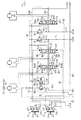
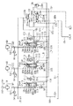
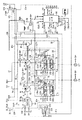
ここで、上記走行体1、フィーダ15、破砕装置20、排出コンベア40、及び磁選機55は、この自走式破砕機に備えられる油圧駆動装置によって駆動される被駆動部材を構成している。図4乃至図6は、本発明の自走式リサイクル製品生産機の一実施の形態を構成する油圧駆動装置の全体構成を表す油圧回路図である。
【0037】
これら図4乃至図6において、この油圧駆動装置は、前述のエンジン61と、このエンジン61によって駆動される可変容量型の第1油圧ポンプ62及び第2油圧ポンプ63と、同様にエンジン61によって駆動される固定容量型のパイロットポンプ64と、第1及び第2油圧ポンプ62,63から吐出される圧油がそれぞれ供給される上記左・右走行用油圧モータ8L,8R、上記フィーダ用油圧モータ19、上記破砕装置用油圧モータ21、上記排出コンベア用油圧モータ48、及び上記磁選機用油圧モータ60と、第1及び第2油圧ポンプ62,63からこれら油圧モータ8L,8R,19,21,48,60に供給される圧油の流れ(方向及び流量、若しくは流量のみ)を制御する6つのコントロールバルブ65,66,67,68,69,70と、前記の運転席35に設けられ、左・右走行用コントロールバルブ66,67(後述)をそれぞれ切り換え操作するための左・右走行用操作レバー36a,37aと、第1及び第2油圧ポンプ62,63の吐出流量Q1,Q2(後述の図8参照)を調整するポンプ制御手段、例えばレギュレータ装置71,72と、例えば運転席35内の後方側(プレクリーナ32の側方)に設けられ、破砕装置20、フィーダ15、排出コンベア40、及び磁選機55の始動・停止等を操作者が指示入力して操作するための操作盤73とを有している。
【0038】
上記6つのコントロールバルブ65〜70は、2位置切換弁又は3位置切換弁であり、破砕装置用油圧モータ21に接続された破砕装置用コントロールバルブ65と、左走行用油圧モータ8Lに接続された左走行用コントロールバルブ66と、右走行用油圧モータ8Rに接続された右走行用コントロールバルブ67と、フィーダ用油圧モータ19に接続されたフィーダ用コントロールバルブ68と、排出コンベア用油圧モータ48に接続された排出コンベア用コントロールバルブ69と、磁選機用油圧モータ60に接続された磁選機用コントロールバルブ70とから構成されている。
【0039】
このとき、第1及び第2油圧ポンプ62,63のうち、第1油圧ポンプ62は、左走行用コントロールバルブ66及び破砕装置用コントロールバルブ65を介して左走行用油圧モータ8L及び破砕装置用油圧モータ21へ供給するための圧油を吐出するようになっている。これらコントロールバルブ65,66はいずれも、対応する油圧モータ21,8Lへの圧油の方向及び流量を制御可能な3位置切換弁となっており、第1油圧ポンプ62の吐出管路74に接続されたセンターバイパスライン75において、上流側から、左走行用コントロールバルブ66、破砕装置用コントロールバルブ65の順序で配置されている。なお、センターバイパスライン75の最下流側には、ポンプコントロールバルブ76(詳細は後述)が設けられている。
【0040】
一方、第2油圧ポンプ63は、右走行用コントロールバルブ67、フィーダ用コントロールバルブ68、排出コンベア用コントロールバルブ69、及び磁選機用コントロールバルブ70を介し、右走行用油圧モータ8R、フィーダ用油圧モータ19、排出コンベア用油圧モータ48、及び磁選機用油圧モータ60へ供給するための圧油を吐出するようになっている。これらのうち右走行用コントロールバルブ67は対応する右走行用油圧モータ8Rへの圧油の流れを制御可能な3位置切換弁となっており、その他のコントロールバルブ68,69,70は対応する油圧モータ19,48,60への圧油の流量を制御可能な2位置切換弁となっており、第2油圧ポンプ63の吐出管路77に接続されたセンターバイパスライン78a及びこれの下流側にさらに接続されたセンターライン78bにおいて、上流側から、右走行用コントロールバルブ67、磁選機用コントロールバルブ70、排出コンベア用コントロールバルブ69、及びフィーダ用コントロールバルブ68の順序で配置されている。なお、センターライン78bは、最下流側のフィーダ用コントロールバルブ68の下流側で閉止されている。
【0041】
上記コントロールバルブ65〜70のうち、左・右走行用コントロールバルブ66,67はそれぞれ、パイロットポンプ64で発生されたパイロット圧を用いて操作されるセンターバイパス型のパイロット操作弁である。これら左・右走行用コントロールバルブ66,67は、パイロットポンプ64で発生され前述の操作レバー36a,37aを備えた操作レバー装置36,37で所定圧力に減圧されたパイロット圧により操作される。
【0042】
すなわち、操作レバー装置36,37は、操作レバー36a,37aとその操作量に応じたパイロット圧を出力する一対の減圧弁36b,36b及び37b,37bとを備えている。操作レバー装置36の操作レバー36aを図4中a方向(又はその反対方向、以下対応関係同じ)に操作すると、パイロット圧がパイロット管路79(又はパイロット管路80)を介して左走行用コントロールバルブ66の駆動部66a(又は駆動部66b)に導かれ、これによって左走行用コントロールバルブ66が図4中上側の切換位置66A(又は下側の切換位置66B)に切り換えられ、第1油圧ポンプ62からの圧油が吐出管路74、センターバイパスライン75、及び左走行用コントロールバルブ66の切換位置66A(又は下側の切換位置66B)を介して左走行用油圧モータ8Lに供給され、左走行用油圧モータ8Lが順方向(又は逆方向)に駆動される。
【0043】
なお、操作レバー36aを図4に示す中立位置にすると、左走行用コントロールバルブ66はばね66c,66dの付勢力で図4に示す中立位置に復帰し、左走行用油圧モータ8Lは停止する。
【0044】
同様に、操作レバー装置37の操作レバー37aを図4中b方向(又はその反対方向)に操作すると、パイロット圧がパイロット管路81(又はパイロット管路82)を介し右走行用コントロールバルブ67の駆動部67a(又は駆動部67b)に導かれて図4中上側の切換位置67A(又は下側の切換位置67B)に切り換えられ、右走行用油圧モータ8Rが順方向(又は逆方向)に駆動されるようになっている。操作レバー37aを中立位置にするとばね67c,67dの付勢力で右走行用コントロールバルブ67は中立位置に復帰し右走行用油圧モータ8Rは停止する。
【0045】
ここで、パイロットポンプ64からのパイロット圧を操作レバー装置36,37に導くパイロット導入管路83a,83bには、コントローラ84からの駆動信号St(後述)で切り換えられるソレノイド制御弁85が設けられている。このソレノイド制御弁85は、ソレノイド85aに入力される駆動信号StがONになると図6中左側の連通位置85Aに切り換えられ、パイロットポンプ64からのパイロット圧を導入管路83a,83bを介し操作レバー装置36,37に導き、操作レバー36a,37aによる左・右走行用コントロールバルブ66,67の上記操作を可能とする。
【0046】
一方、駆動信号StがOFFになると、ソレノイド制御弁85はばね85bの復元力で図6中右側の遮断位置85Bに復帰し、導入管路83aと導入管路83bとを遮断すると共に導入管路83bをタンク86へのタンクライン86aに連通させ、この導入管路83b内の圧力をタンク圧とし、操作レバー装置36,37による左・右走行用コントロールバルブ66,67の上記操作を不可能とするようになっている。
【0047】
破砕装置用コントロールバルブ65は、両端にソレノイド駆動部65a,65bを備えたセンターバイパス型の電磁比例弁である。ソレノイド駆動部65a,65bには、コントローラ84からの駆動信号Scrで駆動されるソレノイドがそれぞれ設けられており、破砕装置用コントロールバルブ65はその駆動信号Scrの入力に応じて切り換えられるようになっている。
【0048】
すなわち、駆動信号Scrが破砕装置20の正転(又は逆転、以下、対応関係同じ)に対応する信号、例えばソレノイド駆動部65a及び65bへの駆動信号ScrがそれぞれON及びOFF(又はソレノイド駆動部65a及び65bへの駆動信号ScrがそれぞれOFF及びON)になると、破砕装置用コントロールバルブ65が図4中上側の切換位置65A(又は下側の切換位置65B)に切り換えられる。これにより、第1油圧ポンプ62からの圧油が吐出管路74、センターバイパスライン75、及び破砕装置用コントロールバルブ65の切換位置65A(又は下側の切換位置65B)を介して破砕装置用油圧モータ21に供給され、破砕装置用油圧モータ21が順方向(又は逆方向)に駆動される。
【0049】
なお、このときの破砕装置用油圧モータ21の回転数Ncrが破砕装置用油圧モータ21に設けた回転数センサ(例えば金属式、磁力式、光電式等の公知のもの)150によって検出され、その検出信号はコントローラ84へ入力される。またこのときの破砕装置用油圧モータ21の負荷圧力Pcrが上記破砕装置用コントロールバルブ65より上流側から分岐して設けた圧力センサ151によって検出され、その検出信号はコントローラ84へ入力される。
【0050】
駆動信号Scrが破砕装置20の停止に対応する信号、例えばソレノイド駆動部65a及び65bへの駆動信号ScrがともにOFFになると、コントロールバルブ65がばね65c,65dの付勢力で図4に示す中立位置に復帰し、破砕装置用油圧モータ21は停止する。
【0051】
ポンプコントロールバルブ76は、流量を圧力に変換する機能を備えるものであり、前記のセンターバイパスライン75とタンクライン86bとを絞り部分76aaを介して接続・遮断可能なピストン76aと、このピストン76aの両端部を付勢するばね76b,76cと、前記のパイロットポンプ64の吐出管路87にパイロット導入管路88a(後述)及びパイロット導入管路88c(同)を介して上流側が接続されてパイロット圧が導かれ、下流側がタンクライン86cに接続され、かつ前記のばね76bによってリリーフ圧が可変に設定される可変リリーフ弁76dとを備えている。
【0052】
このような構成により、ポンプコントロールバルブ76は以下のように機能する。すなわち、上述したように左走行用コントロールバルブ66及び破砕装置用コントロールバルブ65はセンターバイパス型の弁となっており、センターバイパスライン75を流れる流量は、各コントロールバルブ66,65の操作量(すなわちスプールの切換ストローク量)により変化する。各コントロールバルブ66,65の中立時、すなわち第1油圧ポンプ62へ要求する各コントロールバルブ66,65の要求流量(言い換えれば左走行用油圧モータ8L及び破砕装置用油圧モータ21の要求流量)が少ない場合には、第1油圧ポンプ62から吐出される圧油のうちほとんどが余剰流量Qt1(後述の図7参照)としてセンターバイパスライン75を介してポンプコントロールバルブ76に導入され、比較的大きな流量の圧油がピストン76aの絞り部分76aaを介してタンクライン86bへ導出される。これにより、ピストン76aは図4中右側に移動するので、ばね76bによるリリーフ弁76dの設定リリーフ圧が低くなり、管路88cから分岐して設けられ後述のネガティブ傾転制御用の第1サーボ弁131へ至る管路90に、比較的低い制御圧力(ネガコン圧)Pc1を発生する。
【0053】
逆に、各コントロールバルブ66,65が操作されて開状態となった場合、すなわち第1油圧ポンプ62へ要求する要求流量が多い場合には、センターバイパスライン75に流れる前記余剰流量Qt1は、油圧モータ8L,21側へ流れる流量分だけ減じられるため、ピストン絞り部分76aaを介しタンクライン86bへ導出される圧油流量は比較的小さくなり、ピストン76aは図4中左側に移動してリリーフ弁76dの設定リリーフ圧が高くなるので、管路90の制御圧力Pc1は高くなる。
【0054】
本実施の形態では、後述するように、この制御圧力(ネガコン圧)Pc1の変動に基づき、第1油圧ポンプ62の斜板62Aの傾転角を制御するようになっている(詳細は後述)。
【0055】
なお、第1及び第2油圧ポンプ62,63の吐出管路74,77から分岐した管路91,92には、リリーフ弁93及びリリーフ弁94がそれぞれ設けられており、第1及び第2油圧ポンプ62,63の吐出圧P1,P2の最大値を制限するためのリリーフ圧の値を、それぞれに備えられたばね93a,94aの付勢力で設定するようになっている。
【0056】
また、タンク86の中には、油温検出手段として作動油の油温Toを検出する公知の油温センサ139が設けられており、その検出信号はコントローラ84へ入力される。
【0057】
フィーダ用コントロールバルブ68は、ソレノイド駆動部68aを備えた電磁比例弁である。ソレノイド駆動部68aには、コントローラ84からの駆動信号Sfで駆動されるソレノイドが設けられており、フィーダ用コントロールバルブ68はその駆動信号Sfの入力に応じて切り換えられるようになっている。すなわち、駆動信号Sfがフィーダ15を動作させるON信号になると、フィーダ用コントロールバルブ68が図5中上側の切換位置68Aに切り換えられる。
【0058】
これにより、吐出管路77、センターバイパスライン78a、及びセンターライン78bを介し導かれた第2油圧ポンプ63からの圧油は、切換位置68Aに備えられた絞り手段68Aaから、これに接続する管路95、この管路95に設けられた圧力制御弁96(詳細は後述)、切換位置68Aに備えられたポート68Ab、及びこのポート68Abに接続する供給管路97を経て、フィーダ用油圧モータ19に供給され、この油圧モータ19が駆動される。駆動信号Sfがフィーダ15の停止に対応するOFF信号になると、フィーダ用コントロールバルブ68はばね68bの付勢力で図5に示す遮断位置68Bに復帰し、フィーダ用油圧モータ19は停止する。
【0059】
なお、このときのフィーダ用油圧モータ19の回転数Nfがフィーダ用油圧モータ19に設けた回転数センサ(例えば金属式、磁力式、光電式等の公知のもの)152によって検出され、その検出信号はコントローラ84へ入力される。またこのときのフィーダ用油圧モータ19の負荷圧力Pfが上記供給管路97から分岐して設けた圧力センサ153によって検出され、その検出信号はコントローラ84へ入力される。
【0060】
排出コンベア用コントロールバルブ69は、上記フィーダ用コントロールバルブ68同様、そのソレノイド駆動部69aにコントローラ84からの駆動信号Scomで駆動されるソレノイドが設けられる。駆動信号Scomが排出コンベア40を動作させるON信号になると、コンベア用コントロールバルブ69は図5中上側の連通位置69Aに切り換えられ、センターライン78bからの圧油が、切換位置69Aの絞り手段69Aaから、管路98、圧力制御弁99(詳細は後述)、切換位置69Aのポート69Ab、及びこのポート69Abに接続する供給管路100を介し排出コンベア用油圧モータ48に供給されて駆動される。駆動信号Scomが排出コンベア40の停止に対応するOFF信号になると、排出コンベア用コントロールバルブ69はばね69bの付勢力で図5に示す遮断位置69Bに復帰し、排出コンベア用油圧モータ48は停止する。
【0061】
なお、このときのコンベア用油圧モータ48の負荷圧力Pcomが供給管路100から分岐して設けた圧力センサ154によって検出され、その検出信号はコントローラ84へ入力される。
【0062】
磁選機用コントロールバルブ70は、上記フィーダ用コントロールバルブ68及び排出コンベア用コントロールバルブ69同様、ソレノイド駆動部70aのソレノイドがコントローラ84からの駆動信号Smで駆動される。駆動信号SmがON信号になると、磁選機用コントロールバルブ70は図5中上側の連通位置70Aに切り換えられ、圧油が絞り手段70Aa、管路101、圧力制御弁102(詳細は後述)、ポート70Ab、供給管路103を介し磁選機用油圧モータ60に供給されて駆動される。駆動信号SmがOFF信号になると、磁選機用コントロールバルブ70はばね70bの付勢力で遮断位置70Bに復帰する。
【0063】
なお、このときの磁選機用油圧モータ60の負荷圧力Pmが供給管路103から分岐して設けた圧力センサ155によって検出され、その検出信号はコントローラ84へ入力される。
【0064】
なお、上記したフィーダ用油圧モータ19、排出コンベア用油圧モータ48、及び磁選機用油圧モータ60への圧油の供給に関し、回路保護等の観点から、供給管路97,100,103とタンクライン86bとの間を接続する管路104,105,106に、それぞれリリーフ弁107,108,109が設けられている。
【0065】
ここで、前述した管路95,98,101に設けた圧力制御弁96,99,102に係わる機能について説明する。
フィーダ用コントロールバルブ68の切換位置68Aの前記ポート68Ab、排出コンベア用コントロールバルブ69の切換位置69Aの前記ポート69Ab、及び磁選機用コントロールバルブ70の切換位置70Aのポート70Abには、それぞれ、対応するフィーダ用油圧モータ19、排出コンベア用油圧モータ48、磁選機用油圧モータ60の負荷圧力をそれぞれ検出するための負荷検出ポート68Ac、負荷検出ポート69Ac、負荷検出ポート70Acが連通されている。このとき、負荷検出ポート68Acは負荷検出管路110に接続しており、負荷検出ポート69Acは負荷検出管路111に接続しており、負荷検出ポート70Acは負荷検出管路112に接続している。
【0066】
ここで、フィーダ用油圧モータ19の負荷圧力が導かれる前記負荷検出管路110と、排出コンベア用油圧モータ48の負荷圧力が導かれる前記負荷検出管路111とは、さらにシャトル弁113を介して負荷検出管路114に接続され、シャトル弁113を介して選択された高圧側の負荷圧力はこの負荷検出管路114に導かれるようになっている。またこの負荷検出管路114と、磁選機用油圧モータ60の負荷圧力が導かれる前記負荷検出管路112とは、シャトル弁115を介して最大負荷検出管路116に接続され、シャトル弁115で選択された高圧側の負荷圧力が最大負荷圧力として最大負荷検出管路116に導かれるようになっている。
【0067】
そして、この最大負荷検出管路116に導かれた最大負荷圧力は、最大負荷検出管路116に接続する管路117,118,119,120を介して、対応する前記圧力制御弁96,99,102の一方側にそれぞれ伝達される。このとき、圧力制御弁96,99,102の他方側には前記の管路95,98,101内の圧力、すなわち絞り手段68Aa,69Aa,70Aaの下流側圧力が導かれている。
【0068】
以上により、圧力制御弁96,99,102は、コントロールバルブ68,69,70の絞り手段68Aa,69Aa,70Aaの下流側圧力と、フィーダ用油圧モータ19、排出コンベア用油圧モータ48、及び磁選機用油圧モータ60のうちの最大負荷圧力との差圧に応答して作動し、各油圧モータ19,48,60の負荷圧力の変化にかかわらず、前記の差圧を一定値に保持するようになっている。すなわち、絞り手段68Aa,69Aa,70Aaの下流側圧力を、前記の最大負荷圧力よりもばね96a,99a,102aによる設定圧分だけ高くするようになっている。
【0069】
一方、第2油圧ポンプ63の吐出管路77に接続したセンターバイパスライン78a及びセンターライン78bから分岐したブリードオフ管路121には、ばね122aを備えたリリーフ弁(アンロード弁)122が設けられている。このリリーフ弁122の一方側には、最大負荷検出管路116、これに接続する管路123を介し最大負荷圧力が導かれており、またリリーフ弁122の他方側にはポート122bを介しブリードオフ管路121内の圧力が導かれている。これにより、リリーフ弁122は、管路121及びセンターライン78b内の圧力を、前記の最大負荷圧力よりもばね122aによる設定圧分だけ高くするようになっている。すなわち、リリーフ弁122は、管路121及びセンターライン78b内の圧力が、最大負荷圧が導かれる管路123内の圧力にばね122aのばね力分が加算された圧力になったときに、管路121の圧油をポンプコントロールバルブ124を介してタンク86へと導くようになっている。以上の結果、第2油圧ポンプ63の吐出圧が最大負荷圧よりもばね122aによる設定圧分だけ高くなるロードセンシング制御が実現される。
なお、このときばね122aで設定されるリリーフ圧は、前述したリリーフ弁93及びリリーフ弁94の設定リリーフ圧よりも小さい値に設定されている。
【0070】
そして、ブリードオフ管路121のリリーフ弁122より下流側には、前記のポンプコントロールバルブ76と同様の流量−圧力変換機能をもつポンプコントロールバルブ124が設けられており、タンクライン86dに接続されるタンクライン86eと管路121とを絞り部分124aaを介して接続・遮断可能なピストン124aと、このピストン124aの両端部を付勢するばね124b,124cと、前記のパイロットポンプ64の吐出管路87にパイロット導入管路88a及びパイロット導入管路88bを介して上流側が接続されてパイロット圧が導かれ、下流側が上記タンクライン86eに接続され、かつ前記のばね124bによってリリーフ圧が可変に設定される可変リリーフ弁124dとを備えている。
【0071】
このような構成により、破砕作業時において、ポンプコントロールバルブ124は以下のように機能する。すなわち、上述したようにセンターライン78bの最下流側端は閉止されており、また破砕作業時には後述のように右走行用コントロールバルブ67は操作されないため、センターライン78bを流れる圧油の圧力は、フィーダ用コントロールバルブ68、排出コンベア用コントロールバルブ69、磁選機用コントロールバルブ70の操作量(すなわちスプールの切換ストローク量)により変化する。各コントロールバルブ68,69,70の中立時、すなわち第2油圧ポンプ63へ要求する各コントロールバルブ68,69,70の要求流量(言い換えれば各油圧モータ19,48,60の要求流量)が少ない場合には、第2油圧ポンプ63から吐出される圧油はほとんど供給管路97,100,103に導入されないため、余剰流量Qt2(後述の図7参照)としてリリーフ弁122から下流側へ導出され、ポンプコントロールバルブ124に導入される。これにより、比較的大きな流量の圧油がピストン124aの絞り部分124aaを介してタンクライン86eへ導出されるので、ピストン124aは図5中右側に移動してばね124bによるリリーフ弁124dの設定リリーフ圧が低くなり、パイロット導入管路88bから分岐して設けられ後述のネガティブ傾転制御用の第1サーボ弁132へ至る管路125に、比較的低い制御圧力(ネガコン圧)Pc2を発生する。
【0072】
逆に、各コントロールバルブが操作されて開状態となった場合、すなわち第2油圧ポンプ63への要求流量が多い場合には、ブリードオフ管路121に流れる前記余剰流量Qt2が油圧モータ19,48,60側へ流れる流量分だけ減じられるため、ピストン絞り部分124aaを介しタンクライン86eへ導出される圧油流量は比較的小さくなり、ピストン124aは図5中左側に移動してリリーフ弁124dの設定リリーフ圧が高くなるので、管路125の制御圧力Pc2は高くなる。本実施の形態では、後述するように、この制御圧力Pc2の変動に基づき、第2油圧ポンプ63の斜板63Aの傾転角を制御するようになっている(詳細は後述)。
【0073】
以上説明した、圧力制御弁96,99,102による絞り手段68Aa,69Aa,70Aaの下流側圧力と最大負荷圧力との間の制御、及びリリーフ弁122によるブリードオフ管路121内の圧力と最大負荷圧力との間の制御により、絞り手段68Aa,69Aa,70Aaの前後差圧を一定とする圧力補償機能を果たすこととなる。これにより、各油圧モータ19,48,60の負荷圧力の変化にかかわらず、コントロールバルブ68,69,70の開度に応じた流量の圧油を対応する油圧モータに供給できるようになっている。
そして、この圧力補償機能と、ポンプコントロールバルブ124からの制御圧力Pc2の出力に基づく後述の油圧ポンプ63の斜板63Aの傾転角制御とにより、結果として、第2油圧ポンプ63の吐出圧と絞り手段68Aa,69Aa,70Aaの下流側圧力との差が一定に保持されるようになっている(詳細は後述)。
【0074】
また、最大負荷圧が導かれる管路123とタンクライン86eとの間にはリリーフ弁126が設けられ、管路123内の最大圧力をばね126aの設定圧以下に制限し、回路保護を図るようになっている。すなわち、このリリーフ弁126と前記リリーフ弁122とでシステムリリーフ弁を構成しており、管路123内の圧力が、ばね126aで設定された圧力より大きくなると、リリーフ弁126の作用により管路123内の圧力がタンク圧に下がり、これによって前述のリリーフ弁122が作動しリリーフ状態となるようになっている。
【0075】
前記のレギュレータ装置71,72は、傾転アクチュエータ129,130と、第1サーボ弁131,132と第2サーボ弁133,134とを備え、これらのサーボ弁131〜134によりパイロットポンプ64や第1及び第2油圧ポンプ62,63から傾転アクチュエータ129,130に作用する圧油の圧力を制御し、第1及び第2油圧ポンプ62,63の斜板62A,63Aの傾転(すなわち押しのけ容積)を制御するようになっている。
【0076】
傾転アクチュエータ129,130は、両端に大径の受圧部129a,130a及び小径の受圧部129b,130bを有する作動ピストン129c,130cと、受圧部129a,129b及び130a,130bがそれぞれ位置する受圧室129d,129e及び130d,130eとを有する。そして、両受圧室129d,129e及び130d,130eの圧力が互いに等しいときは、作動ピストン129c,130cは受圧面積の差によって図6中右方向に移動し、これによって斜板62A,63Aの傾転は大きくなり、ポンプ吐出流量Q1,Q2が増大する。また、大径側の受圧室129d,130dの圧力が低下すると、作動ピストン129c,130cは図6中左方向に移動し、これによって斜板62A,63Aの傾転が小さくなりポンプ吐出流量Q1,Q2が減少するようになっている。なお、大径側の受圧室129d,130dは第1及び第2サーボ弁131〜134を介して、パイロットポンプ64の吐出管路87に連通する管路135に接続されており、小径側の受圧室129e,130eは直接管路135に接続されている。
【0077】
第1サーボ弁131,132のうち、レギュレータ装置71の第1サーボ弁131は前述したようにポンプコントロールバルブ76からの制御圧力(ネガコン圧)Pc1により駆動されるネガティブ傾転制御用のサーボ弁であり、レギュレータ装置72の第1サーボ弁132は、前述したようにポンプコントロールバルブ124からの制御圧力Pc2により駆動されるネガティブ傾転制御用のサーボ弁であり、これらは互いに同等の構造となっている。
【0078】
すなわち、制御圧力PC1,PC2が高いときは弁体131a,132aが図6中右方向に移動し、パイロットポンプ64からのパイロット圧PPを減圧せずに傾転アクチュエータ129,130の受圧室129d,130dに伝達し、これによって斜板62A,63Aの傾転が大きくなって第1及び第2油圧ポンプ62,63の吐出流量Q1,Q2を増大させる。そして制御圧力PC1,PC2が低下するにしたがって弁体131a,132aがばね131b,132bの力で図6中左方向に移動し、パイロットポンプ64からのパイロット圧PPを減圧して受圧室129d,130dに伝達し、第1及び第2油圧ポンプ62,63の吐出流量Q1,Q2を減少させるようになっている。
【0079】
以上により、レギュレータ装置71の第1サーボ弁131では、前述したポンプコントロールバルブ76の機能と併せてコントロールバルブ65,66の要求流量に応じた吐出流量Q1が得られるよう、具体的にはセンターバイパスライン75から流入しポンプコントロールバルブ76を通過する流量が最小となるように第1油圧ポンプ62の斜板62Aの傾転(吐出流量)を制御する、いわゆるネガティブコントロールが実現される。
【0080】
また、レギュレータ装置72の第1サーボ弁132では、前述したポンプコントロールバルブ124の機能と併せ、コントロールバルブ67,68,69,70の要求流量に応じた吐出流量Q2が得られるよう、具体的にはセンターバイパスライン78aから流入しポンプコントロールバルブ124を通過する流量が最小となるように第2油圧ポンプ63の斜板63Aの傾転(吐出流量)を制御する、いわゆるネガティブコントロールが実現される。
【0081】
なお、このときの上記制御圧力Pc1,Pc2は、管路90,125から分岐して設けた圧力センサ156,157によってそれぞれ検出され、その検出信号はコントローラ84へ入力される。
【0082】
以上のような構成の結果実現される、前記ポンプコントロールバルブ76,124及び前記レギュレータ装置71,72によるポンプ吐出流量の制御特性を図7及び図8を用いて説明する。
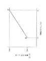
図7は、第1油圧ポンプ62から吐出されセンターバイパスライン75を介してポンプコントロールバルブ76のピストン絞り部分76aaへ導かれる前記余剰流量Qt1、又は第2油圧ポンプ63から吐出されリリーフ弁122を介してポンプコントロールバルブ124の前記ピストン絞り部分124aaへ導かれる前記余剰流量Qt2と、このときポンプコントロールバルブ76,124の前記可変リリーフ弁76d,124dの機能によって発生される前記制御圧力Pc1,Pc2との関係を表した図である。また、図8は、上記制御圧力Pc1,Pc2と第1及び第2油圧ポンプ62,63のポンプ吐出流量Q1,Q2との関係を示した図である。
【0083】
これらの図7及び図8において、コントロールバルブ65,66(又はコントロールバルブ67,70,69,68、以下対応関係同じ)の要求流量が多く第1油圧ポンプ62(又は第2油圧ポンプ63)からポンプコントロールバルブ76(又はポンプコントロールバルブ124)への余剰流量Qt1(又は余剰流量Qt2)が全くないと制御圧力Pc1(又は制御圧力Pc2)は最大値P1となり(図7中の点▲1▼)、この結果、図8中の点▲1▼′に示すように、ポンプ吐出流量Q1(又はポンプ吐出流量Q2)は最大値Qmaxとなる。
【0084】
コントロールバルブ65,66(又はコントロールバルブ67,70,69,68)の要求流量が減少して第1油圧ポンプ62(又は第2油圧ポンプ63)からポンプコントロールバルブ76(又はポンプコントロールバルブ124)への余剰流量Qt1(又はQt2)が増加するにつれて、図7中実線Aで示すように、制御圧力Pc1(又は制御圧力Pc2)は前記最大値P1からほぼ直線的に減少し、この結果、図8に示すように、ポンプ吐出流量Q1(又はポンプ吐出流量Q2)も前記最大値Qmaxからほぼ直線的に減少する。
【0085】
そして、図7において、コントロールバルブ65,66(又はコントロールバルブ67,70,69,68)の要求流量がさらに減少し余剰流量Qt1(又はQt2)がさらに増加して制御圧力Pc1(又はPc2)がタンク圧PTまで減少すると(図7中の点▲2▼)、図8中の点▲2▼′に示すようにポンプ吐出流量Q1(又はポンプ吐出流量Q2)は最小値Qminとなるが、これ以降は、可変リリーフ弁76d,124dが全開状態となり、余剰流量Qt1(又はQt2)が増加しても制御圧力Pc1(又はPc2)はタンク圧PTのままとなり、ポンプ吐出流量Q1(又はQ2)も最小値Qminのままとなる(図8中の点▲2▼′)。
【0086】
この結果、前述したように、コントロールバルブ65,66の要求流量に応じた吐出流量Q1が得られるよう第1油圧ポンプ62の斜板62Aの傾転を制御するネガティブコントロールや、コントロールバルブ67,70,69,68の要求流量に応じた吐出流量Q2が得られるよう第2油圧ポンプ63の斜板63Aの傾転を制御するネガティブコントロールを実現するようになっている。
【0087】
図4乃至図6に戻り、第2サーボ弁133,134は、いずれも入力トルク制限制御用のサーボ弁で、互いに同一の構造となっている。すなわち、第2サーボ弁133,134は、第1及び第2油圧ポンプ62,63の吐出圧P1,P2により作動する弁であり、それら吐出圧P1,P2が、第1及び第2油圧ポンプ62,63の吐出管路74,77から分岐して設けられた吐出圧検出管路136a〜c,137a〜cを介し、操作駆動部133aの受圧室133b,133c及び操作駆動部134aの受圧室134b,134cにそれぞれ導かれるようになっている。
【0088】
すなわち、第1及び第2油圧ポンプ62,63の吐出圧の和P1+P2によって操作駆動部133a,134aに作用する力がばね133d,134dで設定されるばね力によって弁体133e,134eに作用する力より小さいときは、弁体133e,134eは図6中右方向に移動し、パイロットポンプ64から第1サーボ弁131,132を介し導かれたパイロット圧PPを減圧せずに傾転アクチュエータ129,130の受圧室129d,130dに伝達し、これによって第1及び第2油圧ポンプ62,63の斜板62A,63Aの傾転を大きくして吐出流量を大きくする。
【0089】
そして、第1及び第2油圧ポンプ62,63の吐出圧の和P1+P2による力がばね133d,134dのばね力設定値による力よりも大きくなるにしたがって弁体133e,134eが図6中左方向に移動し、パイロットポンプ64から第1サーボ弁131,132を介し導かれたパイロット圧PPを減圧して受圧室129d,130dに伝達し、これによって第1及び第2油圧ポンプ62,63の吐出流量を減少させるようになっている。
【0090】
以上により、第1及び第2油圧ポンプ62,63の吐出圧P1,P2が上昇するに従って第1及び第2油圧ポンプ62,63の吐出流量Q1,Q2の最大値Q1max,Q2maxが小さく制限され、第1及び第2油圧ポンプ62,63の入力トルクの合計をエンジン61の出力トルク以下に制限するように第1及び第2油圧ポンプ62,63の斜板62A,63Aの傾転が制御されるいわゆる入力トルク制限制御(馬力制御)が実現される。このとき、さらに詳細には、第1油圧ポンプ62の吐出圧P1と第2油圧ポンプ63の吐出圧P2との和に応じて、第1及び第2油圧ポンプ62,63の入力トルクの合計をエンジン61の出力トルク以下に制限するいわゆる全馬力制御が実現されるようになっている。
【0091】
なお、このときの上記第1及び第2油圧ポンプ62,63の吐出圧P1,P2は、吐出圧検出管路136a,137aから分岐して設けた圧力センサ158,159によってそれぞれ検出され、その検出信号はコントローラ84へ入力される。
【0092】
ここで、本実施の形態では、第1油圧ポンプ62及び第2油圧ポンプ63の両方がほぼ同一の特性に制御される。すなわち、レギュレータ装置71の第2サーボ弁133において第1油圧ポンプ62を制御するときにおける第1及び第2油圧ポンプ62,63の吐出圧の和P1+P2と第1油圧ポンプ62の吐出流量Q1の最大値Q1maxとの関係と、レギュレータ装置72の第2サーボ弁134において第2油圧ポンプ63を制御するときにおける第1及び第2油圧ポンプ62,63の吐出圧の和P1+P2と第2油圧ポンプ63の吐出流量Q2の最大値Q2maxとの関係とが、互いに略同一の関係(例えば10%程度の幅で)となるように、かつ、第1及び第2油圧ポンプ62,63の吐出流量Q1,Q2の最大値Q1max,Q2maxを互いに略同じ値(同)で制限するようになっている。
【0093】
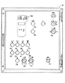
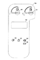
図9は、本発明の自走式リサイクル品生産機の一実施の形態を構成する操作盤73の全体構成を表す正面図である。
【0094】
図9において、操作盤73は、破砕装置20を正転方向に起動させるためのクラッシャ正転起動ボタン73aと、逆転方向に起動させるためのクラッシャ逆転起動ボタン73bと、停止させるためのクラッシャ停止ボタン73cと、上記正転又は逆転時における破砕装置20の動作速度(破砕装置用油圧モータ21の回転速度、回転数)を設定するためのクラッシャ回転数設定ダイヤル73dと、フィーダ15を起動させるためのフィーダ起動ボタン73eと、フィーダ15を停止させるためのフィーダ停止ボタン73fと、上記起動時におけるフィーダ15の動作速度(フィーダ用油圧モータ19の回転速度、回転数)を設定するためのフィーダ速度設定ダイヤル73gと、排出コンベア40を起動させるための排出コンベア起動ボタン73hと、排出コンベア40を停止させるための排出コンベア停止ボタン73iと、磁選機55を起動させるための磁選機起動ボタン73jと、磁選機55を停止させるための磁選機停止ボタン73kと、走行操作を行う走行モード及び破砕作業を行う破砕モードのいずれか一方を選択するためのモード選択スイッチ73lと、エンジン61の回転数を設定するためのエンジン回転数設定ダイヤル73mとを備えている。
【0095】
操作者が上記操作盤73の各種スイッチ及びダイヤルの操作を行うと、その操作信号が前記のコントローラ84に入力される。コントローラ84は、まず第1の機能として、操作盤73からの操作信号に基づき、前述した破砕装置用コントロールバルブ65、フィーダ用コントロールバルブ68、排出コンベア用コントロールバルブ69、磁選機用コントロールバルブ70、及びソレノイド制御弁85のソレノイド駆動部65a,65b、ソレノイド駆動部68a、ソレノイド駆動部69a、ソレノイド駆動部70a、及びソレノイド85aへの前記の駆動信号Scr,Sf,Scom,Sm,Stを生成し、対応するソレノイドにそれらを出力するようになっている。
【0096】
すなわち、操作盤73のモード選択スイッチ73lで「走行モード」が選択された場合には、ソレノイド制御弁85への駆動信号StをONにしてソレノイド制御弁85を図6中左側の連通位置85Aに切り換え、操作レバー36a,37aによる走行用コントロールバルブ66,67の操作を可能とする。操作盤73のモード選択スイッチ73lで「破砕モード」が選択された場合には、ソレノイド制御弁85への駆動信号StをOFFにして図6中右側の遮断位置85Bに復帰させ、操作レバー36a,37aによる走行用コントロールバルブ66,67の操作を不可能とする。
【0097】
また、操作盤73のクラッシャ正転起動ボタン73a(又はクラッシャ逆転起動ボタン73b)が押された場合、破砕装置用コントロールバルブ65のソレノイド駆動部65a(又はソレノイド駆動部65b)への駆動信号ScrをONにするとともにソレノイド駆動部65b(又はソレノイド駆動部65a)への駆動信号ScrをOFFにし、そのときのクラッシャ回転数設定ダイヤル73dの操作量(ダイヤル角度)に応じたストローク量で破砕装置用コントロールバルブ65を図4中上側の切換位置65A(又は下側の切換位置65B)に切り換え、第1油圧ポンプ62からの圧油を破砕装置用油圧モータ21に供給して駆動し、破砕装置20を正転方向(又は逆転方向)にそのときのクラッシャ回転数設定ダイヤル73dの操作量(ダイヤル角度)に応じた回転数で起動する。
【0098】
その後、クラッシャ停止ボタン73cが「停止」側へ押された場合、破砕装置用コントロールバルブ65のソレノイド駆動部65a及びソレノイド駆動部65bへの駆動信号ScrをともにOFFにして図4に示す中立位置に復帰させ、破砕装置用油圧モータ21を停止し、破砕装置20を停止させる。
【0099】
また、操作盤73のフィーダ起動ボタン73eが押された場合、フィーダ用コントロールバルブ68のソレノイド駆動部68aへの駆動信号SfをONにしてそのときのフィーダ速度設定ダイヤル73gの操作量(ダイヤル角度)に応じたストローク量で図5中上側の切換位置68Aに切り換え、第2油圧ポンプ63からの圧油をフィーダ用油圧モータ19に供給して駆動し、フィーダ15をそのときのフィーダ速度設定ダイヤル73gの操作量(ダイヤル角度)に応じた速度で起動する。その後、操作盤73のフィーダ停止ボタン73fが押されると、フィーダ用コントロールバルブ68のソレノイド駆動部68aへの駆動信号SfをOFFにして図5に示す中立位置に復帰させ、フィーダ用油圧モータ19を停止し、フィーダ15を停止させる。
【0100】
同様に、排出コンベア起動・停止ボタン73dが「起動」側へ押された場合、排出コンベア用コントロールバルブ69を図5中上側の切換位置69Aに切り換え、排出コンベア用油圧モータ48を駆動して排出コンベア40を起動し、排出コンベア停止ボタン73iが押されると、排出コンベア用コントロールバルブ69を中立位置に復帰させ、排出コンベア40を停止させる。
【0101】
また、磁選機起動・停止ボタン73eが「起動」側へ押された場合、磁選機用コントロールバルブ70を図5中上側の切換位置70Aに切り換え、磁選機用油圧モータ60を駆動して磁選機55を起動し、磁選機起動・停止ボタン73eが「停止」側へ押されると、磁選機用コントロールバルブ70を中立位置に復帰させ、磁選機55を停止させる。
【0102】
このときコントローラ84は、第2の機能として、操作盤73の操作設定に基づきエンジン61の回転数制御を行う機能を備えている。以下、この機能の詳細について説明する。
図4乃至図6において、138はエンジン61へ燃料を噴射する燃料噴射装置、140はエンジン61の回転数を検出する回転数センサである。燃料噴射装置138には公知のガバナ機構が備えられており、その燃料噴射量をステッピングモータ(ECモータ)の入力パルス数に応じた回転角度(EC角)に応じて制御されるようになっている。コントローラ84は上記エンジン回転数設定ダイヤル73mの操作量(ダイヤル角度)に応じてエンジン目標回転数(回転速度)Noを算出し、これを対応するパルスの形で燃料噴射装置138の上記ステッピングモータへ出力する。ステッピングモータはこのエンジン目標回転数Noに応じた回転角度(EC角)でガバナ機構からの噴射量を制御し、エンジン61をその目標回転数Noで回転させる。このときステッピングモータの回転角度αが検出されてコントローラ84へ入力され、また回転数センサ140は検出したエンジン61の回転数Nをコントローラ84へ出力するようになっている。
【0103】
図9に戻り、操作盤73はまた、上記以外に、エンジン61や各種機器の機械稼働に係わる状態又はその状態量の各種表示、警告等を行う表示モニタ部73Aを備えており、さらにこれに対応して、表示モニタ部73Aの表示切り換えを行うための表示切換ボタン73nと、主として後述のトリップ設定用のセットボタン73oとを備えている。
【0104】
ここで、コントローラ84は、例えば、前述した各種センサで検出した機械稼働に係わる状態量の検出信号及び操作盤73上で操作設定された機械稼働に係わる指示信号のうち、少なくとも一方を入力する入力手段(例えば通信インターフェース(I/O)、D/A変換器等)と、この入力した上記検出信号又は上記指示信号に基づき、通常作業用の第1情報データ(詳細は後述)及び故障時対応用の第2情報データ(詳細は後述)を算出する演算手段(例えばCPU)と、この演算手段で算出した第1情報データ及び第2情報データを、いずれか一方を選択切換表示するための基礎情報として操作盤表示モニタ部73Aへ出力する出力手段(例えば居/O、A/D変換器等)とを有している。
【0105】
そして、このような構成により、各種センサで検出した機械稼働に係わる状態量の検出信号及び操作盤73上で操作設定された機械稼働に係わる指示信号に基づき、その検出値をそのまま(あるいはそれら検出値より所定の演算を行って得た演算値を)通常作業用の第1情報データ(詳細は後述)及び故障時対応用の第2情報データ(詳細は後述)として操作盤73へ出力する第3の機能を備えている。
【0106】
すなわち、この第3の機能は、上述した回転数センサ140,150,152からの検出値N,Ncr,Nf、圧力センサ151,153,154,155,156,157,158,159からの検出値Pcr,Pf,Pcom,Pm,Pc1,Pc2,P1,P2、燃料噴射装置138のステッピングモータからの回転角度α、油温センサ139からの検出油温To、水温センサからの検出水温Tw、燃料センサからの燃料残量Hf、エアフィルタ圧力センサからの検出圧力差Ploss、オルタネータからの電圧信号(エンジン起動検出信号)Eg等と、操作盤73のセットボタン73o、エンジン回転数設定ダイヤル73m、クラッシャ回転数設定ダイヤル73d、及びフィーダ設定ダイヤル73gからの操作設定指示値とをそれぞれ入力し、それらに基づき、その検出値・指示値をそのまま(あるいはそれら検出値・指示値より所定の演算を行って得た演算値を)、通常作業用の第1情報データ(詳細は後述)及び故障時対応用の第2情報データ(詳細は後述)として操作盤73の表示モニタ部73Aへ出力する。操作盤73は、それらに基づき、表示モニタ部73Aにおいて、エンジン61や各種機器の機械稼働に係わる状態又はその状態量の各種表示、警告等を行う。
【0107】
図10は、本発明の自走式リサイクル品生産機の一実施の形態を構成する操作盤73の表示モニタ部73Aの詳細構成を表す図9中要部拡大図である。
【0108】
図10において、160はエンジン61のラジエータ水の水温Twを表示する水温計、161は燃料タンクの燃料残量Hfを表示する燃料計、162はその残量Hfが所定値以下となった場合に燃料補給が必要である旨の警告表示を行う燃料残量警告灯、163はエアフィルタ前後の圧力損失Plossが所定値以上となった場合にエアフィルタの清掃又は交換が必要である旨の警告表示を行うエアフィルタ目詰まり警告灯、164はオルタネータからの電圧信号Egが所定範囲外となった場合に電気系統の以上が発生している旨の警告表示を行うチャージランプ、165はエンジン61のラジエータ水の水温Twが所定値以上となった場合にラジエータ水の以上上昇を警告表示するオーバヒート警告灯である。
【0109】
また、166は、液晶表示部である。本発明の要部は、この液晶表示部166に、通常作業用の第1情報データ及び故障時対応用の第2情報データを選択的に表示することにある。以下、その詳細を説明する。
【0110】
(1)通常作業モード
このモードは、液晶表示部166に上記した第1情報データを表示させるモードである。第1情報データとして、「アワーメータ(エンジン稼働時間)」、「トリップメータ1(稼働設定時間)」、「トリップメータ2(稼働設定時間)」、「エンジン実回転数」、及び「作動油温度」をそれぞれ表示させることができる。
【0111】
システムの起動直後には、この通常作業モードとなり、かつ自動的に「アワーメータ」が表示される。この「アワメータ」表示は、オルタネータからの電圧信号Egが入力されている時間をコントローラ84内部のタイマでカウントして求めた機械製造以降の累計稼働時間を、例えば1時間単位「h」で小数点1桁(0.1時間=6分)まで表示する。なお、このアワメータ表示中は、液晶表示部166内に所定のアワメータマーク(図示せず)が点滅し、また機械稼働中は、小数点が点滅するようになっている。
【0112】
この「アワメータ」表示状態から、操作盤73の表示切換ボタン73nを1回押すと、「トリップ1」表示へ、2回押すと「トリップ1」表示へ移行する。
【0113】
これらのトリップ表示は、ユーザ(操作者)が設定した所定の(目標)稼働時間に対し、その後の残余時間がどれだけあるかを示すものである。この例では「トリップ1」「トリップ2」の2つの表示状態が設定されている(言い換えれば目標稼動時間を2種類設定できる)。「トリップ」表示へ移行後、操作盤73のセットボタン73oを押すことにより、目標稼働時間をその時点から何時間とするかを任意に設定する(あるいは例えば50時間、100時間、200時間等予め設定された選択肢の中から随時選択するようにしてもよい)。設定後、稼働時間の経過と共にその設定時間から減算されていき、液晶表示部166に目標稼働時間までの残り時間が表示される。「トリップ」表示状態の間は、所定のトリップマーク(トリップ1又はトリップ2)が液晶表示部166に表示され、また、上記残り時間が0以下になるとそのトリップマークが所定時間だけ点滅し設定時間になったことを確実に報知するようになっている。
【0114】
上記「トリップ1」表示状態から操作盤73の表示切換ボタン73nを2回押すか、「トリップ2」表示状態から表示切換ボタン73nを1回押すと、「エンジン実回転数」表示へ移行する。この「エンジン実回転数」表示は、回転数センサ140で検出したエンジン回転数Nを、例えばrpm単位「min−1」で小数点1桁まで表示するようになっている。
【0115】
上記「エンジン実回転数」表示状態から操作盤73の表示切換ボタン73nを1回押すと、「作動油温度」表示へ移行する。この「作動油温度」表示は、油温センサ139で検出した作動油の温度Toを、例えば「℃」単位で小数点1桁まで表示するものである。
【0116】
(2)故障時対応モード
このモードは、例えば何らかの理由で稼働中にいずれかの機器やエンジン等が故障した場合に使用するものであり、液晶表示部166に上記した第2情報データを表示させるモードである。第2情報データとして、「ポンプ吐出圧1」、「ポンプ吐出圧2」、「ネガコン制御圧力1」、「ネガコン制御圧力2」、「エンジン回転数ダイヤル操作角度」、「エンジン目標回転数」、「ステッピングモータ回転角」、「クラッシャ実動作速度」、「フィーダ実動作速度」、「クラッシャ速度指示値」、「フィーダ速度指示値」、「クラッシャ負荷圧」、「フィーダ負荷圧」、「コンベア負荷圧」、及び「磁選機負荷圧」をそれぞれ表示させることができる。
【0117】
この「故障時対応モード」は、例えば操作盤73の表示切換ボタン73nを押しながら同じく操作盤73に設けたエンジン61起動用のキースイッチ(図示せず)をONにすることによって移行する。言い換えれば、上記表示切換ボタン73nとキースイッチの同時操作を行うか行わないかによって、第1情報データ及び第2情報データのいずれを表示するか選択することができる。そして表示モニタ部73Aには、この選択に関係なく、コントローラ84からの第1情報データ及び第2情報データの両方が入力されており、上記の選択結果によって、液晶表示部166にて通常作業モードの第1情報データか故障時対応モードの第2情報データかを選択した後、切り換え表示する。
【0118】
この故障時対応モードでは、上記のようにして移行後、まず最初に自動的に「ポンプ吐出圧1」が表示される。この「ポンプ吐出圧1」表示は、圧力センサ158で検出した第1油圧ポンプ62の吐出圧P1を、例えば「Mpa」単位で小数点1桁まで表示する。なお、この「ポンプ吐出圧1」表示状態から表示切換ボタン73nを1回押すと、「ポンプ吐出圧2」表示へ移行し、圧力センサ159で検出した第2油圧ポンプ63の吐出圧P2を同様に表示する。
【0119】
上記「ポンプ吐出圧1」表示状態から表示切換ボタン73nを2回押すか、「ポンプ吐出圧2」表示状態から表示切換ボタン73nを1回押すと、「ネガコン制御圧力1」表示へ移行する。この「ネガコン制御圧力1」表示は、圧力センサ156で検出したポンプコントロールバルブ76からの制御圧力Pc1を、例えば「Mpa」単位で小数点1桁まで表示する。なお、この「ネガコン制御圧力1」表示状態から表示切換ボタン73nを1回押すと、「ネガコン制御圧力2」表示へ移行し、圧力センサ157で検出したポンプコントロールバルブ124からの制御圧力Pc2を同様に表示する。
【0120】
上記「ネガコン制御圧力1」表示状態から表示切換ボタン73nを2回押すか、「ネガコン制御圧力2」表示状態から表示切換ボタン73nを1回押すと、「エンジン回転数ダイヤル操作角度」表示へ移行する。この「エンジン回転数ダイヤル操作角度」表示は、操作盤73のエンジン回転数設定ダイヤル73mの操作量(操作角度)に応じて実際に操作量信号として生じる電圧値を、例えば「V」単位で小数点1桁まで表示する。
【0121】
上記「エンジン回転数ダイヤル操作角度」表示状態から表示切換ボタン73nを1回押すと、「エンジン目標回転数」表示へ移行する。この「エンジン目標回転数」表示は、上述したエンジン回転数設定ダイヤル73mの操作量(操作角度)に応じて生じる電圧値を、コントローラ84内部の演算手段で演算処理して求めたエンジン61の目標回転数Noを、例えばrpm単位「1/min」で小数点1桁まで表示する。
【0122】
上記「エンジン目標回転数」表示状態から表示切換ボタン73nを1回押すと、「ステッピングモータ回転角」表示へ移行する。この「ステッピングモータ回転角」表示は、上述したエンジン61の目標回転数Noを基に駆動する燃料噴射装置138のステッピングモータ(EC)の実際の回転角を、実際に駆動信号として生じる電圧値の形で、例えば「V」単位で小数点1桁まで表示する。
【0123】
上記「ステッピングモータ回転角」表示状態から表示切換ボタン73nを1回押すと、「クラッシャ実動作速度」表示へ移行する。この「クラッシャ実動作速度」表示は、回転数センサ150で検出した破砕装置用油圧モータ21の回転数Ncrを、例えばrpm単位「1/min」で小数点1桁まで表示する。なお、この「クラッシャ実動作速度」表示状態から表示切換ボタン73nを1回押すと、「フィーダ実動作速度」表示へ移行する。
【0124】
上記「クラッシャ実動作速度」表示状態から表示切換ボタン73nを1回押すと、「フィーダ実動作速度」表示へ移行する。この「フィーダ実動作速度」表示は、回転数センサ152で検出したフィーダ用油圧モータ19の回転数Nfを、例えばrpm単位「1/min」で小数点1桁まで表示する。なお、この「フィーダ実動作速度」表示状態から表示切換ボタン73nを1回押すと、「コンベア実動作速度」表示へ移行する。
【0125】
上記「フィーダ実動作速度」表示状態から表示切換ボタン73nを1回押すと、「クラッシャ速度指示値」表示へ移行する。この「クラッシャ速度指示値」表示は、操作盤73のクラッシャ回転数設定ダイヤル73dの操作量(操作角度)に応じて実際に操作量信号として生じる電圧値を、例えば「V」単位で小数点1桁まで表示する。
【0126】
上記「クラッシャ速度指示値」表示状態から表示切換ボタン73nを1回押すと、「フィーダ速度指示値」表示へ移行する。この「フィーダ速度指示値」表示は、操作盤73のフィーダ設定ダイヤル73gの操作量(操作角度)に応じて実際に操作量信号として生じる電圧値を、例えば「V」単位で小数点1桁まで表示する。
【0127】
上記「フィーダ速度指示値」表示状態から表示切換ボタン73nを1回押すと、「クラッシャ負荷圧」表示へ移行する。この「クラッシャ負荷圧」表示は、圧力センサ151で検出した破砕用油圧モータ21の負荷圧Pcrを、例えば「Mpa」単位で小数点1桁まで表示する。
【0128】
上記「クラッシャ負荷圧」表示状態から表示切換ボタン73nを1回押すと、「フィーダ負荷圧」表示へ移行する。この「フィーダ負荷圧」表示は、圧力センサ153で検出したフィーダ用油圧モータ19の負荷圧Pfを、例えば「Mpa」単位で小数点1桁まで表示する。
【0129】
上記「フィーダ負荷圧」表示状態から表示切換ボタン73nを1回押すと、「コンベア負荷圧」表示へ移行する。この「コンベア負荷圧」表示は、圧力センサ154で検出したコンベア用油圧モータ48の負荷圧Pcomを、例えば「Mpa」単位で小数点1桁まで表示する。
【0130】
上記「コンベア負荷圧」表示状態から表示切換ボタン73nを1回押すと、「磁選機負荷圧」表示へ移行する。この「磁選機負荷圧」表示は、圧力センサ155で検出した磁選機用油圧モータ60の負荷圧Pmを、例えば「Mpa」単位で小数点1桁まで表示する。なお、この「磁選機負荷圧」表示状態から表示切換ボタン73nを1回押すと、再度「ポンプ吐出圧1」表示へ戻るようになっている。
【0131】
以上において、破砕装置20は、特許請求の範囲各項記載のリサイクル原料に対し所定のリサイクル処理を行う処理装置を構成し、フィーダ15、排出コンベア40、及び磁選機55は、処理装置によるリサイクル処理作業に関連する作業を行う補助機械を構成し、破砕装置用油圧モータ21、フィーダ用油圧モータ19、コンベア用油圧モータ48、及び磁選機用油圧モータ60が、ポンプから吐出される圧油が供給され処理装置又は補助機械を駆動する油圧アクチュエータを構成する。
【0132】
また、回転数センサ140,150,152、圧力センサ151,153,154,155,156,157,158,159、燃料噴射装置138のステッピングモータの回転角検出部、油温センサ139、水温センサ、燃料センサ、エアフィルタ圧力センサ(又は機械的センサ)、及びオルタネータの電圧信号検出部が、機械稼働に係わる各機器の状態量を検出する検出手段を構成する。なお、操作盤73のセットボタン73o、エンジン回転数設定ダイヤル73m、クラッシャ回転数設定ダイヤル73d、及びフィーダ設定ダイヤル73gが、機械稼働に係わる指示値を操作設定するための設定手段として機能する。
【0133】
また、操作盤73のセットボタン73o及びエンジン61起動用のキースイッチが、前述したように、通常作業用の第1情報データ及び故障時対応用の第2情報データのいずれを表示するかが選択される第2選択手段を構成する。そして、コントローラ84が、検出手段の検出値及び設定手段の指示値のうち少なくとも一方に基づき、通常作業用の第1情報データ又は故障時対応用の第2情報データを算出し出力する情報処理手段を構成する。また、操作盤表示モニタ部73Aの液晶表示部166が、情報処理手段から出力された第1情報データ又は第2情報データを選択的に表示する表示手段を構成する。
【0134】
次に、上記構成の本発明の自走式破砕機の一実施の形態の動作及び作用効果を以下に説明する。
上記構成の自走式破砕機において、破砕作業時には、操作者は、操作盤73のモード選択スイッチ73lで「破砕モード」を選択して走行操作を不可能にした後、磁選機起動ボタン73j、排出コンベア起動ボタン73h、クラッシャ正転起動ボタン73a、及びフィーダ起動ボタン73eを順次押す。
【0135】
上記の操作により、コントローラ84から磁選機用コントロールバルブ70のソレノイド駆動部70aへの駆動信号SmがONになって磁選機用コントロールバルブ70が図5中上側の切換位置70Aに切り換えられ、またコントローラ84から排出コンベア用コントロールバルブ69のソレノイド駆動部69aへの駆動信号ScomがONになって排出コンベア用コントロールバルブ69が図5中上側の切換位置69Aに切り換えられる。さらに、コントローラ84から破砕装置用コントロールバルブ65のソレノイド駆動部65aへの駆動信号ScrがONになるとともにソレノイド駆動部65bへの駆動信号ScrがOFFになり、破砕用コントロールバルブ65が図4中上側の切換位置65Aに切り換えられ、またフィーダ用コントロールバルブ68のソレノイド駆動部68aへの駆動信号SfがONになってフィーダ用コントロールバルブ68が図5中上側の切換位置68Aに切り換えられる。
【0136】
これにより、第2油圧ポンプ63からの圧油がセンターバイパスライン78a及びセンタライン78bへ導入され、さらに磁選機用油圧モータ60、排出コンベア用油圧モータ48、及びフィーダ用油圧モータ19に供給され、磁選機55、排出コンベア40、及びフィーダ15が起動される。一方、第1油圧ポンプ62からの圧油が破砕装置用油圧モータ65に供給されて破砕装置20が正転方向に起動される。
【0137】
そして、例えば油圧ショベル等によりホッパ12に被破砕物を投入すると、ホッパ12で受け入れられた被破砕物は、フィーダ15によって搬送される。このとき、櫛歯プレート17の櫛歯間の間隙よりも小さなもの(ズリ等)は、櫛歯間の隙間からシュート14を介して排出コンベア40上に導かれ、それより大きなものは破砕装置20へと搬送される。破砕装置20に搬送された被破砕物は、固定歯及び動歯により所定の粒度に砕かれ、下方の排出コンベア40上に落下する。排出コンベア40上に導かれた破砕物やズリ等は、後方(図1中右側)に向かって搬送され、その途中で上記磁選機55により鉄筋等の異物を吸着除去された上で、最終的に機外に排出される。
【0138】
そして、このような通常作業時において、操作盤表示モニタ部73Aの液晶表示部166には、第1情報データとして、「アワーメータ」、「トリップメータ1」、「トリップメータ2」、「エンジン実回転数」、及び「作動油温度」のうちいずれかが表示される。
【0139】
ここで、上記のようにして作業を行っているとき、何らかの理由で稼働中にいずれかの機器やエンジン61等が故障する場合が考えられる。この場合、上記のように液晶表示部に表示される第1情報データだけではその異常発生箇所の特定及びその異常発生原因を特定することは困難である。
【0140】
そこで、本実施形態においては、このような故障発生時には、フィーダ停止ボタン73f、クラッシャ停止ボタン73c、排出コンベア停止ボタン73i、及び磁選機停止ボタン73kを順次押し、各機器を一旦停止させる。また、エンジン61起動用のキースイッチをOFFにしてエンジン61も停止させる。その後、操作盤73の表示切換ボタン73nを押しながらエンジン61起動用のキースイッチをONにして「故障時対応モード」に移行させ、これによって第2情報データとしての「ポンプ吐出圧1」、「ポンプ吐出圧2」、「ネガコン制御圧力1」、「ネガコン制御圧力2」、「エンジン回転数ダイヤル操作角度」、「エンジン目標回転数」、「ステッピングモータ回転角」、「クラッシャ実動作速度」、「フィーダ実動作速度」、「クラッシャ速度指示値」、「フィーダ速度指示値」、「クラッシャ負荷圧」、「フィーダ負荷圧」、「コンベア負荷圧」、及び「磁選機負荷圧」を液晶表示部166に表示させることができる。
【0141】
したがって、このようにして各データを順次表示させてチェックしていき、例えば信号の流れ上どこまでが正常値でどこからが異常値であるかを判定することによって、どこで異常が発生しているか、及びその異常の原因が何であるかを特定することができる。
【0142】
このことを、具体例を挙げてさらに詳細に説明する。
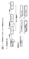
(A)故障例▲1▼〜エンジン回転数設定ダイヤル73mを回してもエンジン61の回転数が変わらない場合(図11)
図11において、この場合の信号の流れは、前述したように、エンジン回転数設定ダイヤル73mの操作量(ダイヤル操作角度)に応じた電圧信号がコントローラ84へ出力され、コントローラ84でその電圧値が演算処理されて求められたエンジン61の目標回転数Noが燃料噴射装置138のステッピングモータ(EC)へ出力され、ステッピングモータがエンジン目標回転数Noに応じた回転角度(EC角)でガバナ機構による噴射量を制御してエンジン61の回転数を制御する。そして、ステッピングモータの回転角度αと、エンジン61の実回転数Nとが、それぞれ検出値としてコントローラ84へ入力されている。
【0143】
このような流れに基づき、本実施形態では、図11に示すように、「故障時対応モード」において、液晶表示部166にまず「エンジン回転数ダイヤル操作角度」表示を行わせ、ダイヤル角度(電圧値)がコントローラ84に入力されているかどうかをチェックする。入力されていなければ、エンジン回転数設定ダイヤル73m自体が不良であることが直ちに判明する。
【0144】
ダイヤル角度が入力されていれば、次に、「ステッピングモータ回転角」表示を行わせ、エンジン61の目標回転数Noを基に駆動する燃料噴射装置138のステッピングモータ(EC)の実際の回転角(電圧値)がダイヤル操作に応じ変化するかどうかをチェックする。変化しなければ、ステッピングモータ自体の不良であることが分かり、変化していれば、ステッピングモータは正常に駆動してガバナ機構から燃料噴射が制御されているはずであるから、エンジン61自体の不良であることが判明する。
【0145】
(B)故障例▲2▼〜クラッシャ回転数設定ダイヤル73dを回しても破砕装置20の回転数が変わらない場合(図12)
図12において、この場合の信号の流れは、前述したように、クラッシャ回転数設定ダイヤル73dの操作量(ダイヤル操作角度)に応じた電圧信号がコントローラ84へ出力され、コントローラ84でその電圧値が演算処理されて求められたソレノイド駆動信号が破砕装置用コントロールバルブ65へ出力される。そして破砕装置用コントロールバルブ65が切り換えられ、余剰流量Qt1が増減するのに応じてポンプコントロールバルブ76からのネガディブコントロール用の制御圧力Pc1が制御され、これに応じて第1サーボ弁131によって第1油圧ポンプ62の吐出圧が制御される。そして、ポンプコントロールバルブ76の制御圧力Pc1と、第1油圧ポンプの吐出圧P1とが、それぞれ検出値としてコントローラ84へ入力されている。
【0146】
このような流れに基づき、本実施形態では、図12に示すように、「故障時対応モード」において、液晶表示部166にまず「クラッシャ速度指示値」表示を行わせ、ダイヤル角度に対応する電圧値がコントローラ84に入力されているかどうかをチェックする。入力されていなければ、クラッシャ回転数設定ダイヤル73d自体が不良であることが直ちに判明する。
【0147】
ダイヤル角度が入力されていれば、次に、「ネガコン制御圧力1」表示を行わせ、圧力センサ156で検出したポンプコントロールバルブ76からの制御圧力Pc1がダイヤル操作に応じ変化するかどうかをチェックする。変化しなければ、破砕装置用コントロールバルブ65か若しくはポンプコントロールバルブ76の不良であることが分かり、変化していれば、第1油圧ポンプ62自体の不良であることが判明する。
【0148】
以上説明したように、本実施の形態によれば、故障発生時には、多数の第2情報データを順次表示させてチェックすることで、どこで異常が発生しているか、及びその異常の原因が何であるかを特定することができる。この結果、従来構造のように外部接続機器を用いることなく、迅速かつ容易に異常発生箇所及び異常発生原因を特定することができる。
【0149】
なお、上記のような故障時において、ユーザ(操作者)側で比較的専門的な知識を持っている場合には、操作者自身で上記第2情報データを一覧してある程度異常発生箇所及び異常発生原因を特定してもよいし、そうでない場合には、操作者からの故障発生の一報を受けたメンテナンス作業員(サービスマン)が当該機械のもとへ赴き、第2情報データを一覧して程度異常発生箇所及び異常発生原因を特定してもよい。いずれの場合でも、従来構造のように外部接続機器を用いることなく、迅速かつ容易に異常発生箇所及び異常発生原因を特定することができる。
【0150】
またこのとき、本実施の形態においては、コントローラ84からは第1情報データと第2情報データの両方を表示モニタ部73Aに出力し、表示モニタ部73A側でキースイッチ+操作盤表示切換ボタン73nを操作したかどうかによっていずれかを選択して表示するようにしている。これにより、コントローラ84において情報データの識別及び選別処理を行う必要がなくなり、コントローラ84側の演算処理負荷を低減できる効果もある。
【0151】
なお、上記本発明の一実施の形態では、破砕装置用コントロールバルブ65を電磁比例弁とし、破砕装置20の動作速度調整時には、主として、操作盤73のクラッシャ回転数設定ダイヤル73dの操作量に応じて破砕装置用コントロールバルブ65のストローク量が変化する(もちろんこれに応じて要求流量も変わることから、結果としてネガティブ傾転制御用第1サーボ弁131を介し第1油圧ポンプ62の吐出流量も増大することになる)ことによって、破砕装置用油圧モータ21への供給圧油量を制御したが、これに限られない。
【0152】
すなわち、例えばネガティブ傾転制御用第1サーボ弁131へ制御圧力Pc1を導く管路90に新たに電磁比例弁を設け、破砕装置用コントロールバルブ65については単なるオン・オフ的に切り替わる切換弁として破砕装置20動作時には全開状態とする一方、破砕装置20の動作速度調整時には操作盤73のクラッシャ回転数設定ダイヤル73dの操作量に応じて上記電磁比例弁の開度を変化させるようにする(言い換えればダイヤル73dの操作量で第1油圧ポンプ62の吐出流量を直接制御する)ようにしてもよい。この場合も、同様の効果を得る。
【0153】
また、以上は、本発明の技術思想を自走式破砕機(自走式リサイクル品生産機)全体で具現化した場合の例であったが、コントローラ84に着目した場合には、本発明の技術思想を、上記自走式リサイクル品生産機に備えられた情報処理装置として具現化してとらえることもできる。
【0154】
すなわちその場合、本発明は、機械稼働に係わる各機器の状態量を検出する複数の検出手段を備えた自走式リサイクル品生産機に設けられる自走式リサイクル品生産機の情報処理装置であって、前記検出手段の検出信号を入力する入力手段と、この入力手段で入力した前記検出信号に基づき、通常作業用の第1情報データと故障時対応用の第2情報データの双方のデータを生成する第2生成手段と、この第2生成手段で生成した前記第1情報データと前記第2情報データの双方のデータ信号を、いずれか一方を選択切換表示するための基礎情報として表示手段に出力する第2出力手段とを備えることを特徴とする自走式リサイクル品生産機の情報処理装置となる。
【0155】
さらに、操作盤73の表示モニタ部73Aに着目した場合には、本発明の技術思想を、上記自走式リサイクル品生産機に備えられた情報表示装置として具現化してとらえることもできる。
【0156】
すなわちその場合、本発明は、機械稼働に係わる各機器の状態量を検出する複数の検出手段を備えた自走式リサイクル品生産機に設けられる自走式リサイクル品生産機の情報表示装置であって、前記検出手段の検出信号に基づき生成された、通常作業用の第1情報データと故障時対応用の第2情報データの双方のデータを入力し、前記自走式リサイクル製品生産機に設けた第2選択手段の選択状況に応じて、その入力した第1情報データ又は第2情報データのいずれか一方のデータを選択的に切換表示することを特徴とする自走式リサイクル品生産機の情報表示装置となる。
【0157】
また、上記本発明の一実施の形態において、コントローラ84からは第1情報データと第2情報データの両方を表示モニタ部73Aに出力し、表示モニタ部73A側でいずれかを選択して表示したのと逆に、キースイッチ+操作盤表示切換ボタン73nを操作したかどうかによってコントローラ84側で第1情報データと第2情報データのいずれかを予め選択し、その選択した情報のみを表示モニタ部73Aに出力して表示させるようにしてもよい。
【0158】
この構成においては、キースイッチ及び操作盤表示切換ボタン73nが通常作業用の第1情報データ及び故障時対応用の第2情報データのいずれを表示するかが選択される第1選択手段を構成する。この場合、コントローラ84から表示モニタ部73Aまでの通信データ量を低減することができ、コントローラ84側の通信負荷を低減できるという効果を奏する。
【0159】
そして、上記本発明の一実施の形態と同様、この変形例の技術思想を、上記自走式リサイクル品生産機に備えられた情報処理装置として具現化してとらえることもできる。
【0160】
すなわちその場合は、機械稼働に係わる各機器の状態量を検出する複数の検出手段を備えた自走式リサイクル品生産機に設けられる自走式リサイクル品生産機の情報処理装置であって、前記検出手段の検出信号を入力する入力手段と、この入力手段で入力した前記検出信号に基づき、通常作業用の第1情報データ又は故障時対応用の第2情報データを生成する第1生成手段と、前記自走式リサイクル製品生産機に設けた第1選択手段の選択状況に応じて、前記第1生成手段で生成した前記第1情報データ又は前記第2情報データのいずれか一方のデータを選択的に表示手段に切換出力する第1出力手段とを備えることを特徴とする自走式リサイクル品生産機の情報処理装置となる。
【0161】
また操作盤73の表示モニタ部73Aに着目した場合には、その技術思想を、上記自走式リサイクル品生産機に備えられた情報表示装置として具現化してとらえることもでき、機械稼働に係わる各機器の状態量を検出する複数の検出手段を備えた自走式リサイクル品生産機に設けられる自走式リサイクル品生産機の情報表示装置であって、前記検出手段の検出信号に基づき生成された、通常作業用の第1情報データ又は故障時対応用の第2情報データのいずれか一方のデータ信号を入力し、その入力した第1情報データ又は第2情報データのいずれか一方のデータを選択的に表示することを特徴とする自走式リサイクル品生産機の情報表示装置となる。
【0162】
なお、以上は、本発明を、破砕装置としてジョークラッシャをそなえた自走式破砕機に適用した場合を例にとって説明したが、これに限られない。すなわち、破砕装置として、複数個の刃物を備えた打撃板を高速回転させ、この打撃板からの打撃及び反発板との衝突を用いて被破砕物を衝撃的に破砕する破砕装置(いわゆるインパクトクラッシャ)や、ロール状の回転体(ロータ)に破砕用の刃物を取り付けたものを一対としてそれら一対を互いに逆方向へ回転させ、それら回転体の間に被破砕物を挟み込んで破砕を行う回転式破砕装置(いわゆるロールクラッシャを含む6軸破砕機等)や、平行に配置された軸にカッタを備え、互いに逆回転させることにより被破砕物をせん断する破砕装置(いわゆるシュレッダを含む2軸せん断機等)や、固定歯に対して動歯を揺動させ、これらの間に被破砕物を導入して破砕を行う破砕装置(いわゆるジョークラッシャ)や、木材、枝木材、建設廃木等の木材をカッタを備えた回転体(ロータ)に投入することにより細片にする木材破砕装置等を備えた自走式破砕機(木材破砕装置を備える場合には特に自走式木材破砕機と称する場合もある)に対して本発明を適用してもよい。
【0163】
また自走式破砕機にも限られず、例えば、ガス管等の埋設工事、上下水道工事、及びその他の道路工事・基礎工事等において発生する建設発生土のうち埋め戻しに適さないものをリサイクル原料として土砂ホッパに受け入れ、導入コンベアによって処理装置としての混合装置へ導き、この混合装置で土質改良材とともに混合処理し、混合物を排出コンベア上に落下させ、この排出コンベアでリサイクル用の土砂製品又は半製品(=リサイクル品)として排出する自走式土質改良機に対して本発明を適用してもよい。これらの場合も、上記本発明の一実施の形態と同様に、液晶表示部等の表示部に第1情報データと第2情報データとを選択的に表示することによって、外部接続機器を用いることなく迅速かつ容易に異常発生箇所及び異常発生原因を特定できるという効果を得る。
【0164】
【発明の効果】
本発明によれば、故障発生時には、多数の第2情報データを順次表示させてチェックしていくことで、どこで異常が発生しているか、及びその異常の原因が何であるかを特定することができる。この結果、従来構造のように外部接続機器を用いることなく、迅速かつ容易に異常発生箇所及び異常発生原因を特定することができる。
【図面の簡単な説明】
【図1】本発明の自走式リサイクル品生産機の一実施の形態の全体構造を表す側面図である。
【図2】本発明の自走式リサイクル品生産機の一実施の形態の全体構造を表す上面図である。
【図3】本発明の自走式リサイクル品生産機の一実施の形態の全体構造を表す正面図である。
【図4】本発明の自走式リサイクル製品生産機の一実施の形態を構成する油圧駆動装置の全体構成を表す油圧回路図である。
【図5】本発明の自走式リサイクル製品生産機の一実施の形態を構成する油圧駆動装置の全体構成を表す油圧回路図である。
【図6】本発明の自走式リサイクル製品生産機の一実施の形態を構成する油圧駆動装置の全体構成を表す油圧回路図である。
【図7】本発明の自走式リサイクル製品生産機の一実施の形態を構成するポンプコントロールバルブ及びレギュレータ装置によるポンプ吐出流量の制御特性の説明図である。
【図8】本発明の自走式リサイクル製品生産機の一実施の形態を構成するポンプコントロールバルブ及びレギュレータ装置によるポンプ吐出流量の制御特性の説明図である。
【図9】本発明の自走式リサイクル品生産機の一実施の形態を構成する操作盤の全体構成を表す正面図である。
【図10】本発明の自走式リサイクル品生産機の一実施の形態を構成する操作盤の表示モニタ部の詳細構成を表す図9中要部拡大図である。
【図11】本発明の自走式リサイクル品生産機の一実施の形態において、故障発生時における処理手順の一例を表す説明図である。
【図12】本発明の自走式リサイクル品生産機の一実施の形態において、故障発生時における処理手順の一例を表す説明図である。
【符号の説明】
15 フィーダ(補助機械)
19 フィーダ用油圧モータ
20 破砕装置(処理装置)
21 破砕装置用油圧モータ
40 排出コンベア(補助機械)
48 コンベア用油圧モータ
55 磁選機(補助機械)
60 磁選機用油圧モータ(油圧アクチュエータ)
61 エンジン(原動機)
62 第1油圧ポンプ
63 第2油圧ポンプ
73 操作盤
73A モニタ表示部
73d クラッシャ回転数設定ダイヤル(設定手段)
73g フィーダ設定ダイヤル(設定手段)
73m エンジン回転数設定ダイヤル(設定手段)
73o セットボタン(設定手段;選択手段)
84 コントローラ(情報処理手段;情報処理装置)
139 油温センサ(検出手段)
140 回転数センサ(検出手段)
150 回転数センサ(検出手段)
151 圧力センサ(検出手段)
152 回転数センサ(検出手段)
153 圧力センサ(検出手段)
154 圧力センサ(検出手段)
155 圧力センサ(検出手段)
156 圧力センサ(検出手段)
157 圧力センサ(検出手段)
158 圧力センサ(検出手段)
159 圧力センサ(検出手段)
166 液晶表示部(表示手段;情報表示装置)[0001]
TECHNICAL FIELD OF THE INVENTION
The present invention relates to a self-propelled recycle machine including a self-propelled crusher equipped with a crushing device for crushing an object to be crushed, and a self-propelled soil conditioner equipped with a mixing device for adding and mixing a soil improving material to soil and the like. The present invention relates to a product production machine, an information processing device used for the same, and an information display device.
[0002]
[Prior art]
Under the background of the recent promotion of waste recycling, the use of self-propelled recycle product production machines such as self-propelled crushers and self-propelled soil improvement machines is expanding.
[0003]
Self-propelled crushers are used for various types of large and small rocks, construction waste, industrial waste, etc. generated at construction sites, such as concrete blocks taken out during building demolition and asphalt blocks discharged during road repair. Crushed material) is used as a recycled material. For example, a crushed material put into a hopper as a receiving means at the upper part of a self-propelled crusher by a hydraulic shovel or the like is processed as a processing device by a feeder provided below the hopper, for example. And crushed to a predetermined size by this crushing device. The crushed material falls from a space below the crusher onto a discharge conveyor below the crusher, and is conveyed by the discharge conveyor. During this transportation, a magnetic separator placed above the discharge conveyor adsorbs and removes, for example, rebar pieces mixed in the concrete lump, and outputs a crushed product or semi-finished product for recycling (hereinafter, “recycled product”). To be carried out).
[0004]
On the other hand, self-propelled soil improvement machines are, for example, reclaimed materials that are not suitable for backfilling, such as buried gas pipes, water and sewage works, and other road and foundation works. For example, the recycled raw material (soil and sand) charged into the earth and sand hopper as a receiving means at the upper part of the self-propelled soil improvement machine by a hydraulic shovel or the like is mixed as a processing device by an introduction conveyor provided below the earth and sand hopper, for example. The mixture is mixed with the soil conditioner using this mixing device, and the mixture is dropped onto a discharge conveyor. The self-propelled soil conditioner uses this discharge conveyor as earth and sand products or semi-finished products (= recycled products) for recycling. It is designed to be carried out.
[0005]
In addition, as the mixing device, a stirring means (paddle mixer) having a plurality of stirring blades (paddles) provided on a plurality of rotating shafts is used to stir and mix while gradually transferring the earth and sand and the soil improving material from the introduction side to the discharge side. It is equipped with a so-called mixing type mixing device and a plurality of rotary impactors that rotate around the rotation axis.The earth and sand and the soil improvement material are pre-crushed with a rotary cutter at high altitude and dropped by their own weight. There is a so-called crushing type mixing device that crushes the earth mass finely by being hit with the rotary hitter and mixes it with the soil improving material.
These self-propelled recycle product production machines are equipped with, for example, the above-described crushing device and mixing device as processing devices for performing a recycling process, such as crawler tracks, feeders, introduction conveyors, discharge conveyors, and magnetic separators. At the same time, the actuator is driven by a hydraulically driven actuator (in this case, a hydraulic motor for a processing device such as a hydraulic motor for a crushing device and a hydraulic motor for a mixing device). That is, at least one hydraulic pump is driven by the prime mover (engine), and the hydraulic oil discharged from the hydraulic pump is supplied to and driven by the processing unit hydraulic motor. At this time, for example, the direction and the flow rate of the pressure oil supplied to the hydraulic motor for the processing device are controlled by the control valve means for the processing device.
[0006]
At this time, various sensors such as the processing device, feeder, discharge conveyor, magnetic separator, and the state quantity related to the engine are detected by various sensors, and information based on the detected values is used to operate some useful information during normal work. There is one that displays the information to the operator at the seat (for example, see Patent Document 1).
[0007]
According to this conventional technology, in a self-propelled crusher, which is an example of a self-propelled recycle product production machine, an instrument panel is provided on a control panel arranged beside a driver's seat on which an operator rides, and the instrument panel is provided with the instrument panel. In addition, a water temperature gauge of engine cooling water (radiator water), an engine fuel gauge, and an hour meter indicating the operating time of the engine are displayed.
[0008]
[Patent Document 1]
JP 2000-325823 A
[0009]
[Problems to be solved by the invention]
In the above prior art, as described above, although the state quantity related to each device and engine such as a processing device, a feeder, a discharge conveyor, and a magnetic separator is detected by various sensors, it is displayed to an operator in a driver's seat. Of the information based on the various detected values, only the engine cooling water temperature, the engine fuel remaining amount, and the engine operating time are included.
[0010]
Therefore, if any device, engine, or the like breaks down during operation for some reason, it is difficult to specify the location of the abnormality and the cause of the abnormality only from the display information. For this reason, although it is not clearly described in the above-mentioned prior art gazette, in such a case, in such a case, a maintenance worker (serviceman) who has received a report of the occurrence of a failure from the operator may acquire and acquire information. Go to the machine with an external connection device for display (for example, a personal computer), connect the external connection device to the control panel, and process devices, feeders, discharge conveyors, magnetic separators, etc. detected by various sensors. It is necessary to acquire and display the above-mentioned state quantity data relating to each of the devices and the engine, thereby identifying the location of the abnormality and the cause of the abnormality.
[0011]
As described above, in the conventional technique, in the event of a failure, an external device must be prepared and connected without fail in order to identify the location of the abnormality and to identify the cause of the abnormality. There is still room for improvement in terms of easy failure handling.
[0012]
SUMMARY OF THE INVENTION An object of the present invention is to provide a self-propelled recycle product production machine capable of quickly and easily specifying an abnormality occurrence location and an abnormality occurrence cause without using an external connection device in the event of a failure, and an information processing apparatus and an information display apparatus used for the same. Is to provide.
[0013]
[Means for Solving the Problems]
(1) In order to achieve the above object, a self-propelled recycle product production machine according to the present invention includes a plurality of detection means for detecting a state quantity of each device related to machine operation, and a detection signal from the detection means, Information processing means for generating first information data for normal operation and second information data for failure handling, and outputting the generated data signal; and the first information output from the information processing means. Display means for selectively displaying data or the second information data.
[0014]
In the present invention, based on the detection value of the detection means, the information processing means, for example, the first operation data for normal work such as the operating time of the prime mover, the working oil temperature of the hydraulic actuator, or the discharge pressure of the hydraulic pump, Calculate and output the second information data for failure handling such as the load pressure of the hydraulic actuator, the actual operating speed of the processing device / auxiliary machine, the rotational speed instruction value of the prime mover, the operating speed instruction value of the processing device / auxiliary machine Then, the display means selectively displays the first information data or the second information data.
[0015]
Thus, during normal work, the first information data such as the operation time of the prime mover is displayed on the display means in the same manner as in the conventional structure, but when a failure occurs, the display means displays detailed information of each device or prime mover. The second information data such as the hydraulic pump discharge pressure can be displayed. Therefore, when a failure occurs, a large number of pieces of second information data are sequentially displayed and checked. For example, by determining where the signal flow is a normal value and where the value is an abnormal value, where the abnormality occurs, And the cause of the abnormality can be specified. As a result, it is possible to quickly and easily specify the location of the abnormality and the cause of the abnormality without using an external connection device as in the conventional structure.
[0016]
(2) In the above (1), preferably, the information processing means selects the one of the first information data and the second information data to be displayed according to a selection state of the first selection means. The data signal of one of the first information data and the second information data is output.
[0017]
In this way, by outputting to the display means the one selected as the first information data or the second information data by the information processing means, the amount of communication data from the information processing means to the display means can be reduced. Thus, the communication load on the information processing means can be reduced.
[0018]
(3) In the above (1), preferably, the information processing means outputs a data signal of both the first information data and the second information data, and the display means outputs the first information data. And displaying one of the first information data and the second information data in accordance with a selection state of the second selection means for selecting which of the first information data and the second information data to display.
[0019]
As described above, both the first information data and the second information data are output from the information processing means to the display means, and one of them is selected and displayed on the display means side. It is not necessary to perform the identification and selection processing, and the processing load on the information processing means can be reduced.
[0020]
(4) In the above (2) or (3), more preferably, a processing device for performing a predetermined recycling process on the recycled material, an auxiliary machine for performing an operation related to the recycling process by the processing device, and a motor A hydraulic pump driven by the prime mover, and a hydraulic actuator supplied with pressurized oil discharged from the hydraulic pump and driving the processing device or the auxiliary machine. As the data, at least one of a discharge pressure of the hydraulic pump, a load pressure of the hydraulic actuator, an actual operation speed of the processing device, and an actual operation speed of the auxiliary machine detected by the detection means is displayed.
[0021]
(5) In the above (2) or (3), preferably, a processing device for performing a predetermined recycling process on the recycled material, an auxiliary machine for performing an operation related to the recycling process by the processing device, and a motor A hydraulic pump driven by the prime mover, a hydraulic actuator supplied with pressure oil discharged from the hydraulic pump to drive the processing device or the auxiliary machine, and setting means for setting an operation state of each device. The display means displays at least one of the rotation speed of the prime mover, the operation speed of the processing device, and the operation speed of the auxiliary machine set by the setting means as the failure response data. I do.
[0022]
(6) In order to achieve the above object, the present invention provides a self-propelled recycle product provided in a self-propelled recycle product production machine provided with a plurality of detection means for detecting a state quantity of each device related to machine operation. In an information processing device of a production machine, input means for inputting a detection signal of the detection means, and first information data for normal work or second information for failure handling based on the detection signal input by the input means. A first generation unit for generating data; and the first information data or the second information generated by the first generation unit according to a selection state of a first selection unit provided in the self-propelled recycle product production machine. First output means for selectively switching and outputting any one of the data to the display means.
[0023]
(7) In order to achieve the above object, the present invention provides a self-propelled recycle product provided in a self-propelled recycle product production machine provided with a plurality of detection means for detecting a state quantity of each device related to machine operation. In an information processing apparatus of a production machine, input means for inputting a detection signal of the detection means, and first information data for normal work and second information for failure handling based on the detection signal input by the input means. A second generation unit for generating both data of the data, and a data signal for selecting and displaying one of the first information data and the second information data generated by the second generation unit. Second output means for outputting to the display means as basic information.
[0024]
(8) In order to achieve the above object, the present invention provides a self-propelled recycle product provided in a self-propelled recycle product production machine provided with a plurality of detection means for detecting a state quantity of each device related to machine operation. In the information display device of the production machine, a data signal of one of the first information data for normal work and the second information data for failure handling, which is generated based on the detection signal of the detection means, is input. One of the input first information data and second information data is selectively displayed.
[0025]
(9) In order to achieve the above object, the present invention provides a self-propelled recycle product provided in a self-propelled recycle product production machine provided with a plurality of detection means for detecting a state quantity of each device related to machine operation. In the information display device of the production machine, data of both the first information data for normal work and the second information data for failure handling, which are generated based on the detection signal of the detection means, are inputted, One of the input first information data and the input second information data is selectively switched and displayed in accordance with the selection state of the second selection means provided in the recycled product production machine.
[0026]
BEST MODE FOR CARRYING OUT THE INVENTION
Hereinafter, an embodiment of a self-propelled recycle product production machine of the present invention will be described with reference to the drawings.
FIG. 1 is a side view showing the entire structure of one embodiment of a self-propelled recycle product production machine of the present invention, FIG. 2 is a top view thereof, and FIG. 3 is a front view seen from the left side in FIG. It is. 1 to 3, this embodiment is an embodiment in which a self-propelled crusher is taken as an example of a self-propelled recycle product production machine.
[0027]
[0028]
[0029]
[0030]
[0031]
[0032]
[0033]
[0034]
[0035]
[0036]
Here, the traveling
[0037]
4 to 6, the hydraulic drive unit includes the above-described
[0038]
The six
[0039]
At this time, of the first and second
[0040]
On the other hand, the second
[0041]
Of the
[0042]
That is, the
[0043]
When the operating
[0044]
Similarly, when the operating
[0045]
Here, a
[0046]
On the other hand, when the drive signal St is turned off, the
[0047]
The
[0048]
That is, the drive signal Scr is a signal corresponding to the normal rotation (or reverse rotation, hereinafter, the same relationship) of the
[0049]
The rotation speed Ncr of the
[0050]
When the drive signal Scr is a signal corresponding to the stop of the crushing
[0051]
The
[0052]
With such a configuration, the
[0053]
Conversely, when each of the
[0054]
In the present embodiment, as will be described later, the tilt angle of the
[0055]
In addition, relief pipes 91 and 92 branching from
[0056]
A known
[0057]
The
[0058]
Thereby, the pressure oil from the second
[0059]
The rotation speed Nf of the feeder
[0060]
Similarly to the
[0061]
Note that the load pressure Pcom of the conveyor
[0062]
As with the
[0063]
At this time, the load pressure Pm of the hydraulic motor for
[0064]
With respect to the supply of the pressurized oil to the feeder
[0065]
Here, the functions related to the
The port 68Ab at the
[0066]
Here, the
[0067]
The maximum load pressure guided to the maximum
[0068]
As described above, the
[0069]
On the other hand, a relief valve (unload valve) 122 provided with a spring 122a is provided in the center bypass line 78a connected to the discharge line 77 of the second
At this time, the relief pressure set by the spring 122a is set to a value smaller than the set relief pressure of the
[0070]
A
[0071]
With such a configuration, during the crushing operation, the
[0072]
Conversely, when each control valve is operated to be opened, that is, when the required flow rate to the second
[0073]
As described above, the control between the downstream pressures of the throttle means 68Aa, 69Aa, 70Aa and the maximum load pressure by the
The pressure compensation function and the tilt angle control of the
[0074]
Further, a
[0075]
The
[0076]
The tilting
[0077]
Of the
[0078]
That is, when the control pressures PC1 and PC2 are high, the valve bodies 131a and 132a move rightward in FIG. 6, and the pressure receiving chambers 129d and 129d of the
[0079]
As described above, in the
[0080]
Further, in the
[0081]
Note that the control pressures Pc1 and Pc2 at this time are detected by
[0082]
The control characteristics of the pump discharge flow rate by the
FIG. 7 shows the surplus flow rate Qt1 discharged from the first
[0083]
7 and 8, the
[0084]
The required flow rate of the
[0085]
In FIG. 7, the required flow rate of the
[0086]
As a result, as described above, the negative control for controlling the tilt of the
[0087]
4 to 6, the
[0088]
That is, the force acting on the operation driving parts 133a, 134a by the sum P1 + P2 of the discharge pressures of the first and second
[0089]
Then, as the force based on the sum P1 + P2 of the discharge pressures of the first and second
[0090]
As described above, as the discharge pressures P1 and P2 of the first and second
[0091]
The discharge pressures P1, P2 of the first and second
[0092]
Here, in the present embodiment, both the first
[0093]
FIG. 9 is a front view showing the entire configuration of the
[0094]
9, a
[0095]
When the operator operates various switches and dials of the
[0096]
That is, when the “running mode” is selected by the mode selection switch 73l of the
[0097]
When the crusher normal
[0098]
Thereafter, when the crusher stop button 73c is pushed to the "stop" side, the drive signal Scr to both the solenoid drive unit 65a and the solenoid drive unit 65b of the crushing
[0099]
When the
[0100]
Similarly, when the discharge conveyor start /
[0101]
When the magnetic separator start /
[0102]
At this time, the
4 to 6,
[0103]
Returning to FIG. 9, the
[0104]
Here, the
[0105]
With this configuration, based on the detection signals of the state quantities related to the machine operation detected by the various sensors and the instruction signals related to the machine operation set on the
[0106]
That is, the third function includes the detection values N, Ncr, Nf from the
[0107]
FIG. 10 is an enlarged view of a main part in FIG. 9 showing a detailed configuration of the
[0108]
In FIG. 10,
[0109]
[0110]
(1) Normal work mode
This mode is a mode in which the above-described first information data is displayed on the liquid
[0111]
Immediately after the system is started, the normal operation mode is set, and the "hour meter" is automatically displayed. This “hour meter” display indicates the cumulative operating time since the machine was manufactured by counting the time during which the voltage signal Eg from the alternator is being input by the timer inside the
[0112]
When the
[0113]
These trip displays indicate how much time remains after the predetermined (target) operating time set by the user (operator). In this example, two display states of “
[0114]
When the
[0115]
When the
[0116]
(2) Failure mode
This mode is used, for example, when any device, engine, or the like fails during operation for some reason, and is a mode in which the above-described second information data is displayed on the liquid
[0117]
The "failure response mode" is shifted by, for example, turning on a key switch (not shown) for starting the
[0118]
In the failure handling mode, "pump
[0119]
When the
[0120]
When the
[0121]
When the
[0122]
When the
[0123]
When the
[0124]
When the
[0125]
When the
[0126]
When the
[0127]
When the
[0128]
When the
[0129]
When the
[0130]
When the
[0131]
In the above, the crushing
[0132]
In addition,
[0133]
As described above, the set button 73o of the
[0134]
Next, an operation and an effect of the embodiment of the self-propelled crusher of the present invention having the above configuration will be described below.
In the self-propelled crusher having the above configuration, during the crushing operation, the operator selects the “crushing mode” with the mode selection switch 73l of the
[0135]
By the above operation, the drive signal Sm from the
[0136]
Thereby, the pressure oil from the second
[0137]
When the crushed object is put into the
[0138]
During such a normal operation, the
[0139]
Here, when the work is performed as described above, it is conceivable that one of the devices, the
[0140]
Therefore, in the present embodiment, when such a failure occurs, the
[0141]
Therefore, in this manner, each data is sequentially displayed and checked, for example, by judging how far the signal flows to the normal value and from where the abnormal value, the location where the abnormality has occurred, and The cause of the abnormality can be specified.
[0142]
This will be described in more detail with a specific example.
(A) Failure example {circle around (1)} When the rotation speed of the
In FIG. 11, the signal flow in this case is as described above. A voltage signal corresponding to the operation amount (dial operation angle) of the engine
[0143]
Based on such a flow, in the present embodiment, as shown in FIG. 11, in the "failure response mode", the liquid
[0144]
If the dial angle has been input, then a “stepping motor rotation angle” display is performed, and the actual rotation angle of the stepping motor (EC) of the
[0145]
(B) Failure example {circle around (2)} When the rotation speed of the
In FIG. 12, the signal flow in this case is such that a voltage signal corresponding to the operation amount (dial operation angle) of the crusher rotation
[0146]
Based on such a flow, in the present embodiment, as shown in FIG. 12, in the "failure response mode", the liquid
[0147]
If the dial angle has been input, then "
[0148]
As described above, according to the present embodiment, when a failure occurs, a large number of pieces of second information data are sequentially displayed and checked to determine where the abnormality has occurred and what is the cause of the abnormality. Can be specified. As a result, it is possible to quickly and easily specify the location of the abnormality and the cause of the abnormality without using an external connection device as in the conventional structure.
[0149]
If the user (operator) has relatively specialized knowledge at the time of a failure as described above, the operator can view the second information data by himself / herself to list the location and location of the abnormality. The cause of the occurrence may be specified. If not, the maintenance worker (serviceman) who has been notified of the occurrence of the failure by the operator goes to the machine and lists the second information data. The location of the abnormal occurrence and the cause of the abnormal occurrence may be specified. In any case, it is possible to quickly and easily specify the location of the abnormality and the cause of the abnormality without using an external connection device as in the conventional structure.
[0150]
At this time, in the present embodiment, both the first information data and the second information data are output from the
[0151]
In the embodiment of the present invention, the
[0152]
That is, for example, an electromagnetic proportional valve is newly provided in the
[0153]
The above is an example of the case where the technical idea of the present invention is embodied by a self-propelled crusher (self-propelled recycle product production machine) as a whole. The technical idea can be embodied as an information processing device provided in the self-propelled recycle product production machine.
[0154]
That is, in this case, the present invention is an information processing apparatus for a self-propelled recycle product production machine provided in a self-propelled recycle product production machine provided with a plurality of detection means for detecting a state quantity of each device related to machine operation. Input means for inputting a detection signal of the detection means, and based on the detection signal input by the input means, both data of first information data for normal work and second information data for failure handling are A second generating means for generating, and a data signal of both the first information data and the second information data generated by the second generating means as display information as basic information for selectively switching and displaying one of the data signals; And a second output means for outputting the information.
[0155]
Further, when attention is paid to the
[0156]
That is, in this case, the present invention is an information display device of a self-propelled recycle product production machine provided in a self-propelled recycle product production machine provided with a plurality of detection means for detecting a state quantity of each device related to machine operation. Inputting both the first information data for normal work and the second information data for failure handling generated based on the detection signal of the detection means, and providing the data to the self-propelled recycle product production machine. Characterized in that either the input first information data or the second information data is selectively switched and displayed in accordance with the selection status of the second selection means. It becomes an information display device.
[0157]
In the embodiment of the present invention, both the first information data and the second information data are output from the
[0158]
In this configuration, the key switch and the operation panel
[0159]
Then, similarly to the above-described embodiment of the present invention, the technical idea of this modified example can also be embodied as an information processing device provided in the self-propelled recycle product production machine.
[0160]
That is, in this case, the information processing device of the self-propelled recycle product production machine provided in the self-propelled recycle product production machine provided with a plurality of detection means for detecting the state quantity of each device related to the machine operation, wherein Input means for inputting a detection signal of the detection means, and first generation means for generating, based on the detection signal input by the input means, first information data for normal work or second information data for failure handling. Selecting one of the first information data and the second information data generated by the first generation means according to a selection state of a first selection means provided in the self-propelled recycle product production machine. And a first output means for selectively switching and outputting to the display means.
[0161]
In addition, when attention is paid to the
[0162]
In the above, the case where the present invention is applied to a self-propelled crusher having a jaw crusher as a crushing device has been described as an example, but the present invention is not limited to this. That is, as a crushing device, a crushing device (a so-called impact crusher) for rotating a striking plate provided with a plurality of blades at high speed, and crushing the crushed object by using the impact from the striking plate and the collision with the repulsion plate. ) Or a rotary type in which a crushing blade is attached to a roll-shaped rotating body (rotor) as a pair, and the pair is rotated in opposite directions to each other, and the crushed object is sandwiched between the rotating bodies to perform crushing. A crushing device (such as a six-axis crusher including a so-called roll crusher) or a crushing device that includes a cutter on a shaft arranged in parallel and shears an object to be crushed by rotating in opposite directions (a so-called two-axis shearing machine including a shredder) Etc.), a crushing device (so-called jaw crusher) that oscillates moving teeth with respect to fixed teeth and introduces an object to be crushed between them, so-called jaw crusher, wood, branch wood, construction waste Self-propelled crusher equipped with a wood crushing device, etc. that turns wood into small pieces by throwing wood into a rotary body (rotor) equipped with a cutter (especially, a self-propelled wood crusher equipped with a wood crushing device) The present invention may be applied to such a case.
[0163]
It is not limited to self-propelled crushers.For example, crushed soil that is not suitable for backfilling, such as buried gas pipes, water and sewage works, and other road works and foundation works, is recycled. Into the mixing device as a processing device by the introduction conveyor, mix with the soil improvement material using this mixing device, drop the mixture onto the discharge conveyor, and use the discharge conveyor to recycle the sediment product or semi-finished product. The present invention may be applied to a self-propelled soil improvement machine that discharges as a product (= recycled product). Also in these cases, similarly to the above-described embodiment of the present invention, the first information data and the second information data are selectively displayed on the display unit such as the liquid crystal display unit, so that the externally connected device can be used. It is possible to obtain the effect that the location of the abnormality and the cause of the abnormality can be specified quickly and easily without any problem.
[0164]
【The invention's effect】
According to the present invention, when a failure occurs, a large number of pieces of second information data are sequentially displayed and checked, whereby it is possible to specify where an abnormality has occurred and what the cause of the abnormality is. it can. As a result, it is possible to quickly and easily specify the location of the abnormality and the cause of the abnormality without using an external connection device as in the conventional structure.
[Brief description of the drawings]
FIG. 1 is a side view showing an entire structure of a self-propelled recycle product production machine according to an embodiment of the present invention.
FIG. 2 is a top view showing the overall structure of one embodiment of the self-propelled recycle product production machine of the present invention.
FIG. 3 is a front view showing the entire structure of one embodiment of the self-propelled recycle product production machine of the present invention.
FIG. 4 is a hydraulic circuit diagram showing an overall configuration of a hydraulic drive device constituting one embodiment of the self-propelled recycle product production machine of the present invention.
FIG. 5 is a hydraulic circuit diagram showing an entire configuration of a hydraulic drive device constituting one embodiment of a self-propelled recycle product production machine of the present invention.
FIG. 6 is a hydraulic circuit diagram showing an overall configuration of a hydraulic drive device constituting one embodiment of a self-propelled recycled product production machine of the present invention.
FIG. 7 is an explanatory diagram of control characteristics of a pump discharge flow rate by a pump control valve and a regulator device constituting one embodiment of a self-propelled recycle product production machine of the present invention.
FIG. 8 is an explanatory diagram of control characteristics of a pump discharge flow rate by a pump control valve and a regulator device constituting one embodiment of a self-propelled recycle product production machine of the present invention.
FIG. 9 is a front view showing the entire configuration of an operation panel constituting an embodiment of the self-propelled recycle product production machine of the present invention.
FIG. 10 is an enlarged view of a main part in FIG. 9 showing a detailed configuration of a display monitor unit of an operation panel constituting one embodiment of the self-propelled recycle product production machine of the present invention.
FIG. 11 is an explanatory diagram illustrating an example of a processing procedure when a failure occurs in one embodiment of the self-propelled recycle product production machine of the present invention.
FIG. 12 is an explanatory diagram showing an example of a processing procedure when a failure occurs in one embodiment of the self-propelled recycle product production machine of the present invention.
[Explanation of symbols]
15 Feeder (Auxiliary machine)
19 Hydraulic motor for feeder
20 Crushing equipment (processing equipment)
21 Hydraulic motor for crusher
40 Discharge conveyor (auxiliary machine)
48 Hydraulic motor for conveyor
55 Magnetic separator (auxiliary machine)
60 Hydraulic motor for magnetic separator (hydraulic actuator)
61 engine (motor)
62 1st hydraulic pump
63 2nd hydraulic pump
73 Operation panel
73A Monitor display
73d Crusher rotation speed setting dial (setting means)
73g feeder setting dial (setting means)
73m engine speed setting dial (setting means)
73o Set button (setting means; selecting means)
84 controller (information processing means; information processing device)
139 Oil temperature sensor (detection means)
140 Speed sensor (detection means)
150 Speed sensor (detection means)
151 pressure sensor (detection means)
152 speed sensor (detection means)
153 pressure sensor (detection means)
154 pressure sensor (detection means)
155 pressure sensor (detection means)
156 Pressure sensor (detection means)
157 Pressure sensor (detection means)
158 Pressure sensor (detection means)
159 Pressure sensor (detection means)
166 Liquid crystal display (display means; information display device)
Claims (9)
前記検出手段の検出信号に基づき、通常作業用の第1情報データ及び故障時対応用の第2情報データを生成し、その生成したデータ信号を出力する処理を行う情報処理手段と、
この情報処理手段から出力された前記第1情報データ又は前記第2情報データを選択的に表示する表示手段と
を備えたことを特徴とする自走式リサイクル品生産機。A plurality of detection means for detecting a state quantity of each device related to machine operation,
Information processing means for performing processing for generating first information data for normal work and second information data for failure handling based on the detection signal of the detection means, and outputting the generated data signal;
Display means for selectively displaying the first information data or the second information data output from the information processing means, a self-propelled recycle product producing machine.
前記情報処理手段は、前記第1情報データと前記第2情報データのいずれを表示するかを選択する第1選択手段の選択状況に応じて、前記第1情報データ又は前記第2情報データのいずれか一方のデータ信号を出力することを特徴とする自走式リサイクル品生産機。The self-propelled recycled product production machine according to claim 1,
The information processing means selects one of the first information data and the second information data according to a selection state of the first selection means for selecting which of the first information data and the second information data is to be displayed. A self-propelled recycled product production machine that outputs either data signal.
前記情報処理手段は、前記第1情報データと前記第2情報データの双方のデータ信号を出力するとともに、
前記表示手段は、前記第1情報データと前記第2情報データのいずれを表示するかを選択する第2選択手段の選択状況に応じて、前記第1情報データ又は前記第2情報データのいずれか一方のデータを表示することを特徴とする自走式リサイクル品生産機。The self-propelled recycled product production machine according to claim 1,
The information processing means outputs a data signal of both the first information data and the second information data,
The display means may select one of the first information data and the second information data according to a selection state of a second selection means for selecting which of the first information data and the second information data to display. A self-propelled recyclables production machine characterized by displaying one data.
前記検出手段の検出信号を入力する入力手段と、
この入力手段で入力した前記検出信号に基づき、通常作業用の第1情報データ又は故障時対応用の第2情報データを生成する第1生成手段と、
前記自走式リサイクル製品生産機に設けた第1選択手段の選択状況に応じて、前記第1生成手段で生成した前記第1情報データ又は前記第2情報データのいずれか一方のデータを選択的に表示手段に切換出力する第1出力手段と
を備えることを特徴とする自走式リサイクル品生産機の情報処理装置。In an information processing device of a self-propelled recycle product production machine provided in a self-propelled recycle product production machine provided with a plurality of detection means for detecting a state quantity of each device related to machine operation,
Input means for inputting a detection signal of the detection means,
First generation means for generating first information data for normal work or second information data for failure handling based on the detection signal input by the input means;
One of the first information data and the second information data generated by the first generation unit is selectively selected according to a selection state of a first selection unit provided in the self-propelled recycle product production machine. And a first output means for switching and outputting to a display means.
前記検出手段の検出信号を入力する入力手段と、
この入力手段で入力した前記検出信号に基づき、通常作業用の第1情報データと故障時対応用の第2情報データの双方のデータを生成する第2生成手段と、
この第2生成手段で生成した前記第1情報データと前記第2情報データの双方のデータ信号を、いずれか一方を選択切換表示するための基礎情報として表示手段に出力する第2出力手段と
を備えることを特徴とする自走式リサイクル品生産機の情報処理装置。In an information processing device of a self-propelled recycle product production machine provided in a self-propelled recycle product production machine provided with a plurality of detection means for detecting a state quantity of each device related to machine operation,
Input means for inputting a detection signal of the detection means,
Second generation means for generating both data of first information data for normal work and second information data for failure handling based on the detection signal input by the input means;
A second output unit for outputting both data signals of the first information data and the second information data generated by the second generation unit to a display unit as basic information for selectively switching and displaying one of the data signals. An information processing device for a self-propelled recycle product production machine, comprising:
前記検出手段の検出信号に基づき生成された、通常作業用の第1情報データ又は故障時対応用の第2情報データのいずれか一方のデータ信号を入力し、その入力した第1情報データ又は第2情報データのいずれか一方のデータを選択的に表示することを特徴とする自走式リサイクル品生産機の情報表示装置。In an information display device of a self-propelled recycle product production machine provided in a self-propelled recycle product production machine provided with a plurality of detection means for detecting a state quantity of each device related to machine operation,
Either the first information data for normal work or the second information data for failure handling generated based on the detection signal of the detection means is input, and the input first information data or 2. An information display device for a self-propelled recycle product production machine, which selectively displays any one of information data.
前記検出手段の検出信号に基づき生成された、通常作業用の第1情報データと故障時対応用の第2情報データの双方のデータを入力し、前記自走式リサイクル製品生産機に設けた第2選択手段の選択状況に応じて、その入力した第1情報データ又は第2情報データのいずれか一方のデータを選択的に切換表示することを特徴とする自走式リサイクル品生産機の情報表示装置。In an information display device of a self-propelled recycle product production machine provided in a self-propelled recycle product production machine provided with a plurality of detection means for detecting a state quantity of each device related to machine operation,
Inputting both the first information data for normal work and the second information data for failure handling generated based on the detection signal of the detection means, the second information provided in the self-propelled recycle product production machine 2. An information display of a self-propelled recycle product producing machine, characterized in that either one of the input first information data and the second information data is selectively switched and displayed according to the selection status of the two selection means. apparatus.
Priority Applications (1)
| Application Number | Priority Date | Filing Date | Title |
|---|---|---|---|
| JP2002290664A JP2004122002A (en) | 2002-10-03 | 2002-10-03 | Self-traveling type recycled article production machine, information processing device and information display device used for the same |
Applications Claiming Priority (1)
| Application Number | Priority Date | Filing Date | Title |
|---|---|---|---|
| JP2002290664A JP2004122002A (en) | 2002-10-03 | 2002-10-03 | Self-traveling type recycled article production machine, information processing device and information display device used for the same |
Publications (1)
| Publication Number | Publication Date |
|---|---|
| JP2004122002A true JP2004122002A (en) | 2004-04-22 |
Family
ID=32282456
Family Applications (1)
| Application Number | Title | Priority Date | Filing Date |
|---|---|---|---|
| JP2002290664A Pending JP2004122002A (en) | 2002-10-03 | 2002-10-03 | Self-traveling type recycled article production machine, information processing device and information display device used for the same |
Country Status (1)
| Country | Link |
|---|---|
| JP (1) | JP2004122002A (en) |
Cited By (3)
| Publication number | Priority date | Publication date | Assignee | Title |
|---|---|---|---|---|
| US8760292B2 (en) | 2010-03-02 | 2014-06-24 | Verifone, Inc. | Point of sale terminal having enhanced security |
| JP2016180300A (en) * | 2015-03-13 | 2016-10-13 | ヨゼフ フェゲーレ アーゲー | Operation equipment for construction machinery |
| JP2020076223A (en) * | 2018-11-06 | 2020-05-21 | ヤンマー株式会社 | Construction machine |
Citations (9)
| Publication number | Priority date | Publication date | Assignee | Title |
|---|---|---|---|---|
| JPH0596190A (en) * | 1991-10-08 | 1993-04-20 | Ube Ind Ltd | Krassia |
| JPH05104007A (en) * | 1991-10-11 | 1993-04-27 | Ube Ind Ltd | Krassia |
| JPH08173835A (en) * | 1994-12-22 | 1996-07-09 | Koubukuro Kosakusho:Kk | Production of crushed sand and sand-crushing plant |
| JP2000015135A (en) * | 1998-07-06 | 2000-01-18 | Hitachi Constr Mach Co Ltd | Crushed stone treatment system, crushed stone treatment and crushed stone storage section used for the same |
| JP2000024539A (en) * | 1998-07-09 | 2000-01-25 | Komatsu Ltd | Self-propelled wood crushing machine |
| JP2002119885A (en) * | 2000-10-12 | 2002-04-23 | Kawasaki Heavy Ind Ltd | Remote maintenance system of crusher for crushed stone and remote maintenance system of crushed stone plant using the same |
| JP2002187325A (en) * | 2000-12-20 | 2002-07-02 | Matsushita Electric Ind Co Ltd | Printing system |
| JP2002187454A (en) * | 2000-12-18 | 2002-07-02 | Kenwood Corp | Car audio device and its display control method |
| JP2002266671A (en) * | 2001-03-08 | 2002-09-18 | Komatsu Ltd | Engine speed control device for soil improvement machine |
-
2002
- 2002-10-03 JP JP2002290664A patent/JP2004122002A/en active Pending
Patent Citations (9)
| Publication number | Priority date | Publication date | Assignee | Title |
|---|---|---|---|---|
| JPH0596190A (en) * | 1991-10-08 | 1993-04-20 | Ube Ind Ltd | Krassia |
| JPH05104007A (en) * | 1991-10-11 | 1993-04-27 | Ube Ind Ltd | Krassia |
| JPH08173835A (en) * | 1994-12-22 | 1996-07-09 | Koubukuro Kosakusho:Kk | Production of crushed sand and sand-crushing plant |
| JP2000015135A (en) * | 1998-07-06 | 2000-01-18 | Hitachi Constr Mach Co Ltd | Crushed stone treatment system, crushed stone treatment and crushed stone storage section used for the same |
| JP2000024539A (en) * | 1998-07-09 | 2000-01-25 | Komatsu Ltd | Self-propelled wood crushing machine |
| JP2002119885A (en) * | 2000-10-12 | 2002-04-23 | Kawasaki Heavy Ind Ltd | Remote maintenance system of crusher for crushed stone and remote maintenance system of crushed stone plant using the same |
| JP2002187454A (en) * | 2000-12-18 | 2002-07-02 | Kenwood Corp | Car audio device and its display control method |
| JP2002187325A (en) * | 2000-12-20 | 2002-07-02 | Matsushita Electric Ind Co Ltd | Printing system |
| JP2002266671A (en) * | 2001-03-08 | 2002-09-18 | Komatsu Ltd | Engine speed control device for soil improvement machine |
Cited By (8)
| Publication number | Priority date | Publication date | Assignee | Title |
|---|---|---|---|---|
| US8760292B2 (en) | 2010-03-02 | 2014-06-24 | Verifone, Inc. | Point of sale terminal having enhanced security |
| US8988233B2 (en) | 2010-03-02 | 2015-03-24 | Verifone, Inc. | Point of sale terminal having enhanced security |
| US9275528B2 (en) | 2010-03-02 | 2016-03-01 | Verifone, Inc. | Point of sale terminal having enhanced security |
| JP2016180300A (en) * | 2015-03-13 | 2016-10-13 | ヨゼフ フェゲーレ アーゲー | Operation equipment for construction machinery |
| US10209739B2 (en) | 2015-03-13 | 2019-02-19 | Joseph Voegele Ag | Operating device for a construction machine |
| US10496132B2 (en) | 2015-03-13 | 2019-12-03 | Joseph Voegele Ag | Operating device for a construction machine |
| JP2020076223A (en) * | 2018-11-06 | 2020-05-21 | ヤンマー株式会社 | Construction machine |
| JP7001573B2 (en) | 2018-11-06 | 2022-01-19 | ヤンマーパワーテクノロジー株式会社 | Construction machinery |
Similar Documents
| Publication | Publication Date | Title |
|---|---|---|
| JP2004188326A (en) | Self-traveling type crusher | |
| JP5027187B2 (en) | Vibration machine | |
| JP2004122002A (en) | Self-traveling type recycled article production machine, information processing device and information display device used for the same | |
| JP2002001159A (en) | Hydraulic drive assembly for self-propelled recycled article producing machine | |
| JP4261901B2 (en) | Crushing monitoring system | |
| JP2004261758A (en) | Prime mover controller for self-propelled crusher | |
| EP1094160B1 (en) | Fluidized soil material supply machine | |
| JP2000325829A (en) | Device for controlling feeder of self-propelled crushing machine | |
| JP5031664B2 (en) | Self-propelled recycling machine and self-propelled conveyor device | |
| JP2003170081A (en) | Self-propelling crusher | |
| JP2006051453A (en) | Crusher and grizzly feeder | |
| JP4351138B2 (en) | Shearing crusher | |
| JP3790066B2 (en) | Manufacturing method of self-propelled crusher | |
| JPH11197535A (en) | Mobile crusher | |
| JP2002028524A (en) | Prediction device for trapping emissions from self-propelled recycled product production machines | |
| JP2002001157A (en) | Vibration suppressing method for self-propelled crushing machine and self-propelled crushing machine | |
| JP3631044B2 (en) | Hydraulic drive device for self-propelled crusher | |
| JP2004188251A (en) | Self-traveling type crusher | |
| JP2012101165A (en) | Self-traveling recycling machine | |
| JP3748346B2 (en) | Hydraulic drive unit for self-propelled crusher | |
| JP2008110296A (en) | Recycling machine | |
| JP2000325817A (en) | Crawler type crushing machine | |
| JP2003159546A (en) | Self-propelled crusher | |
| JPH11156227A (en) | Driver for crusher | |
| JP2001121024A (en) | Hydraulic drive for self-propelled crusher |
Legal Events
| Date | Code | Title | Description |
|---|---|---|---|
| A621 | Written request for application examination |
Free format text: JAPANESE INTERMEDIATE CODE: A621 Effective date: 20050408 |
|
| A977 | Report on retrieval |
Free format text: JAPANESE INTERMEDIATE CODE: A971007 Effective date: 20070710 |
|
| A131 | Notification of reasons for refusal |
Free format text: JAPANESE INTERMEDIATE CODE: A131 Effective date: 20071009 |
|
| A02 | Decision of refusal |
Free format text: JAPANESE INTERMEDIATE CODE: A02 Effective date: 20080318 |