JP2004122402A - Thermal head holding mechanism - Google Patents
Thermal head holding mechanism Download PDFInfo
- Publication number
- JP2004122402A JP2004122402A JP2002286261A JP2002286261A JP2004122402A JP 2004122402 A JP2004122402 A JP 2004122402A JP 2002286261 A JP2002286261 A JP 2002286261A JP 2002286261 A JP2002286261 A JP 2002286261A JP 2004122402 A JP2004122402 A JP 2004122402A
- Authority
- JP
- Japan
- Prior art keywords
- thermal head
- head
- card
- printing
- type paper
- Prior art date
- Legal status (The legal status is an assumption and is not a legal conclusion. Google has not performed a legal analysis and makes no representation as to the accuracy of the status listed.)
- Pending
Links
Images



Landscapes
- Common Mechanisms (AREA)
- Electronic Switches (AREA)
Abstract
Description
【0001】
【発明の属する技術分野】
本発明は、ラインタイプのサーマルヘッドを用いた熱転写プリンタにおけるサーマルヘッドの保持機構に関する。
【0002】
【従来の技術】
ラインタイプのサーマルヘッドを用いた熱転写プリンタにおいて、サーマルヘッドの保持機構の機能は、以下の3つの位置を制御することにある。すなわち、まず、印字時には、印字媒体にリボンを介してサーマルヘッドを印字位置で圧接させる機能。つぎに、印字媒体をサーマルヘッドとプラテンローラのある印字部に供給する時や、印字中でも印字の無い位置では、印字ヘッドを印字媒体から離間させることにより、リボンの節約を行うリボンセービング機能を行なう際にプラテンローラからサーマルヘッドを圧接解除位置に離間させる機能。そして、リボンカセットの着脱時やサーマルヘッドのクリーニング時には、操作を容易にすることができるように前記圧接解除位置よりさらにプラテンローラからサーマルヘッドを待機位置まで離間させる機能である。従来のサーマルヘッドの保持機構は、これらの機能を達成する手段として、プラテンローラに対して、サーマルヘッドをシャフトを中心に回転する機構か、直線的にに移動する機構のいずれかを用いている。
【0003】
【発明が解決しようとする課題】
プラテンローラに対して、サーマルヘッドをシャフトを中心に回転する機構の場合、機構がコンパクトになるという長所があるが、印字媒体の厚みが変わると、サーマルヘッドと印字媒体との接触角度が変わるので、印字品質が安定しないという欠点があった。また、プラテンローラに対して、サーマルヘッドを直線的に移動する機構の場合、印字媒体の厚さが変わっても、サーマルヘッドと印字媒体との接触角度が変わらないので、印字品質が安定するという長所があるが、機構が大型になり、コストが高くなるという欠点があった。
【0004】
本発明は、上記問題に鑑みてなされたものであり、その目的は、厚みの異なる印字媒体に対しても安定した印字品質を保つと共に、コンパクトで安価なサーマルヘッドの保持機構を提供することにある。
【0005】
【課題を解決するための手段】
前記課題を解決するための解決手段として、本発明のサーマルヘッドの保持機構は、リボンカセットの交換やヘッドのクリーニングなどをおこなう際は、回転運動によりサーマルヘッドを圧接解除位置から待機位置に移動させ、前記圧接解除位置から印字位置までの間は直線的に移動させるようにした。
【0006】
【発明の実施の形態】
以下、図面を参照して本発明の一実施形態について説明する。
【0007】
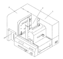
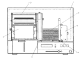
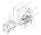
図1は、本発明に係るリボンカセット装置の適用される熱転写プリンタの外観斜視図である。図2は、印字部カバーを外した外観図である。図3は、カード型用紙移送機構の概略構成図である。図4は、プリンタ本体からリボンカセットを外した状態の外観図である。次に、上記熱転写プリンタの印字動作の概要について図1乃至図4に基づいて説明する。
【0008】
まず、図示していないインターフェースを介して接続されているコンピュータからプリンタに印字指令と共に印字データが転送されると、プリンタ1内の電子回路制御部4によって、カード型用紙繰り出し機構6が駆動され、ホッパ部2に積層されたカード型用紙5の下部にある移送爪7が図2中矢印B方向に移動し、ホッパ部に積層されたカード型用紙5の最下部の一枚だけが、ゲート部の上ゲート11と下ゲート12の隙間を1枚通り、カード型用紙移送用ベルト16と図示していないバネで押されたピンチローラ13との間に挟持される。
【0009】
このとき、フロントセンサ18がカード型用紙の先端を検出し、カード型用紙は、移送爪7による移動から、カード型用紙移送用ベルト16による移動に変わり、ホッパ部2から引き出され、カード型用紙移送機構8により、印字部への移送動作を開始する。
【0010】
次に、カード型用紙移送機構8の動作について説明する。まず、カード型用紙移送モータ軸20に取り付けられているプーリ21に巻回された歯付きベルト17が、カード型用紙移送モータに19より駆動され、もう一端の図示していないプーリにより、フレーム23に支持されているシャフト22が回転し、シャフト22に取り付けられた4つのカード型用紙移送用ベルト駆動用プーリ14が回転する。カード型用紙移送用ベルト駆動用プーリ14には、それぞれ、カード型用紙移送用ベルト16が巻回されており、カード型用紙移送用ベルト16のもう一端は、フレーム23に支持された従動シャフト24に取り付けられた4つの従動プーリ15に巻回されている。そして、フレーム23は、シャフト22を中心として回転可能に本体に取り付けられた支持部材25に支持されるとともに、ベルト退避用スプリング26により、カード型用紙移送用ベルト16の先端が下方向すなわち図4中矢印C‘方向に下がる力を受けている。一方、フレーム23には、レバー27が固定されており、レバー27はリンク28を介し、ソレノイド29のプランジャ30に連結されている。リンク28近傍にはベルト位置センサ31があり、ソレノイド29が励磁され、プランジャ30が図4中矢印D‘方向に吸引された時に、ベルト位置センサ31はリンク28により遮蔽される。ソレノイド29の励磁がOFFになり、プランジャ30がベルト退避用スプリング26の力により図4中矢印D方向に引き出された時、ベルト位置センサ31は透過状態になる。このベルト位置センサ31により、カード型用紙移送用ベルト16が上がった移送状態にあるか、又は、下がった退避状態であるかを検出している。カード型用紙の繰り出し時と移送時にはソレノイド29を励磁し、プランジャ30が図4中矢印D‘方向吸引されて、カード型用紙移送用ベルト16が上すなわち図4中矢印C方向に上がった移送状態になっている。カード型用紙の先端がフロントセンサ19の光軸まで達すると、フロントセンサ19の状態が透過から遮蔽に変わり、カード型用紙を検出する。次にカード型用紙は、下側はカード型用紙移送用ベルト16で、上側は用紙押さえスプリング33で引っ張られた押さえ板34に挟まれて移動する。その後、カード型用紙はストッパ35に突き当たり、曲がっていた場合にも、ストッパ35により姿勢をまっすぐに矯正される。このとき、ストッパ35に取り付けられた用紙センサ32がカード型用紙の先端を検出し、カード型用紙移送モータ19を止める。ストッパ35は、用紙の中心に対して画像の中心が同じになるように、用紙サイズに対応して移動するカード型用紙繰り出し機構6の調整量に対して1/2だけ連動して移動する。次に、ソレノイド29の励磁を切り、カード型用紙移送用ベルト16を退避位置方向に下げて、カード型用紙移送用ベルトが印字搬送の邪魔にならないようにする。
【0011】
そして、印字部が作動され、サーマルヘッド36がリボンカセット10にセットされたインクリボン9を介してカード型用紙に押圧される。次いで、プラテンローラ37が回転駆動され、カード型用紙はプリンタ本体の前後方向の前方側(図1中矢印A方向)に移送される。この移送に伴って、電子回路制御部4によって展開された1ライン分の印字データに基づいて、サーマルヘッド36の発熱素子を選択的に動作させると同時にカセット駆動機構38を作動させインクリボン9を巻き取りながら、インクリボン9に塗布されたインクをカード型用紙に転写して所定の印字をおこなう。1枚分の印字が終了すると、サーマルヘッド36の保持機構が作動され、インクリボン9を介してカード型用紙に押圧されていたサーマルヘッド36の圧接を解除して、圧接解除位置まで離間させる。そして、カード型用紙を排出部に排出されるように構成されている。
【0012】
次に、本発明の要部であるサーマルヘッドの保持機構について、図5(a)乃至図8(b)に基づいて説明する。図5(a)は、サーマルヘッドが待機位置にあるときのリボンカセットを外した状態の斜視図、図5(b)は、サーマルヘッドが圧接解除位置にあるときのリボンカセットを外した状態の斜視図、図6(a)は、サーマルヘッドが待機位置にあるときのリボンカセットを外した状態の正面図、図6(b)は、サーマルヘッドが圧接解除位置にあるときのリボンカセットを外した状態の正面図、図7(a)は、サーマルヘッドが圧接解除位置にあるときのリボンカセットを外した状態の正面図、図7(b)は、サーマルヘッドが印字位置にあるときのリボンカセットを外した状態の正面図、図8(a)は、サーマルヘッドが圧接解除位置にあるときのリンク関係図、図8(b)は、サーマルヘッドが印字位置にあるときのリンク関係図である。
【0013】
まず、待機位置と中間位置である圧接解除位置との間をサーマルヘッド36を回転運動により移動させる第1の機構の動作について説明する。サーマルヘッド36が待機位置にあるときは、ヘッドロックレバー39は、図5(a)、図6(a)に示すようにほぼ水平状態にある。ヘッドロックレバー軸40に取り付けられたヘッドロックレバー39を回転させると、ヘッドロックレバー軸40を支点として、同軸に取り付けられたヘッド押付けレバー41が回転し、ヘッド押付けレバー41の両側のピンに取り付けられた押付けローラ42がヘッドユニット43が取り付けられているヘッドフレーム45の上面を回転しながら押すことにより、ヘッドユニット43は、ヘッドブロック回転軸44を支点に回転し、プラテンローラ37に近づいていく。一方、フレーム46に取り付けられたピン47に架けられたスプリング48の片方の端は、ヘッドフレーム45にも架けられており、スプリング48は、ヘッドユニット43がプラテンローラ37に近づくと伸び、ヘッドユニット43を待機位置に戻す方向に働いている。ヘッドロックレバー39のヘッドロックレバー軸40を挟んだ反対側には、図示されていない検出レバーもヘッドロックレバー軸40に取り付いておりヘッドロックレバー39の回転とともに回転する。そして、図5(b)、図6(b)に示すように、ヘッドロックレバー39が垂直になった位置で前記検出レバーが図示されていないマイクロスイッチを押すと、圧接解除位置まで移動したことが検知される。このとき、押付けローラ42は、ヘッドフレーム45の上部に設けられた図示していない穴に入り、前記スプリング48の待機位置へ戻す力に抵抗して、圧接解除位置に固定された状態となる。圧接解除位置は、プリンタの準備が完了した状態であり、カード型用紙の繰り出し動作時、リボンセービング時、印字終了後のカードを排出する時の位置である。サーマルヘッド36を圧接解除位置から待機位置まで戻す場合、まず、ヘッドロックレバー39を垂直位置から水平位置に戻す方向に回転させる。すると、押付けローラ42が、ヘッドフレーム45の上部に設けられた図示していない穴から出て、前記スプリング48によって引っ張られ、ヘッドユニット43は、ヘッドブロック回転軸44を支点に回転し、待機位置まで戻る。以上説明したように、ヘッドロックレバー39の回転により、サーマルヘッド36は待機位置と圧接解除位置の間を往復する。この動作はヘッドブロック回転軸44を支点とした回転運動となる。
【0014】
次に、圧接解除位置である図7(a)に示す中間位置と、図7(b)に示す印字位置との間をサーマルヘッド36を直線的に移動させる第2の機構の動作について、図8により説明する。サーマルヘッド36が圧接解除位置から印字位置に移動させる場合は、パルスモータ51を反時計方向に回転させる。すると、パルスモータ軸に取り付けられたディスク52とディスク52に付随したローラ53も回転し、リンクA54、リンクB55を介してアーム56を引っ張り、シャフト57を中心に回転したプッシャー58がスプリング59を押す。このときスプリング59は、圧縮することなくヘッド固定ブロック60を押し下げる。ヘッド固定ブロック60にはヘッドブラケット61とサーマルヘッド36が取り付けられており、同時にサーマルヘッド36も押し下がることになる。サーマルヘッド36は、インクリボン、カード型用紙などの記録媒体を介してプラテンローラ37に当接して止まるが、さらにパルスモータ51を回転させると、スプリング56が圧縮される。スプリング59の圧縮量が大きくなると、サーマルヘッド36がプラテンローラ37に押し付けられる圧力、すなわち印字圧力が大きくなる。印字圧力の制御は、以下のように行なう。まず、パルスモータ軸に取り付けられたディスク52がパルスモータ51の回転とともに回転すると、ディスク52に設けられたスリット部62が回転するので、センサ63が透過から遮蔽状態になる。印字圧力の制御は、センサ63の検出が透過から遮蔽に変わった時点を基準に所定のパルス数をカウントすることによって行なう。印字圧力を高くする時はカウントするパルス数を多くし、弱くする時は、カウントするパルス数を少なくする。このスプリング59を圧縮させるパルスモータ51のパルス数の設定を適切に行なうことにより、良好な印字品質を得ることができる。パルスモータ51による圧接解除位置と印字位置の間の運動は、ヘッドユニット43の中央がヘッドフレーム45に取り付けられているガイドシャフト49で支持され、さらにヘッドフレーム45の両側にある図示していない角穴に入っているローラ50が上下動作をガイドすることにより直線的な運動となる。サーマルヘッドを印字位置から圧接解除位置まで戻す場合、パルスモータ51を時計方向に回転させ、上記圧接解除位置から印字位置までの移動シーケンスの逆の動作を行なわせる。
【0015】
【発明の効果】
以上説明したように本発明のサーマルヘッドの保持機構は、リボンカセットの交換やヘッドのクリーニングなどをおこなう際は、サーマルヘッドを圧接解除位置から回転運動により待機位置に移動させ、前記圧接解除位置から印字位置までの間は直線的に移動させるようにしたので、コンパクトで、安定した印字品質を提供することができる。
【図面の簡単な説明】
【図1】本発明の一実施形態によるプリンタの外観図である。
【図2】本発明の一実施形態によるプリンタの印字部カバーを外した外観図である。
【図3】本発明の一実施形態によるプリンタのカード型用紙移送機構の概略構成図である。
【図4】本発明の一実施形態によるプリンタのリボンカセットを本体から外した状態の外観図である。
【図5】本発明の一実施形態によるプリンタのサーマルヘッドが待機位置にあるときのリボンカセットを外した状態の斜視図(a)と、サーマルヘッドが圧接解除位置にあるときのリボンカセットを外した状態の斜視図(b)である。
【図6】本発明の一実施形態によるプリンタのサーマルヘッドが待機位置にあるときのリボンカセットを外した状態の正面図(a)、サーマルヘッドが圧接解除位置にあるときのリボンカセットを外した状態の正面図図(b)である。
【図7】本発明の一実施形態によるプリンタのサーマルヘッドが圧接解除位置にあるときのリボンカセットを外した状態の正面図(a)、サーマルヘッドが印字位置にあるときのリボンカセットを外した状態の正面図(b)である。
【図8】本発明の一実施形態によるプリンタのサーマルヘッドが圧接解除位置にあるときのリンク関係図(a)、サーマルヘッドが印字位置にあるときのリンク関係図(b)である。
【符号の説明】
1 プリンタ
2 ホッパ
3 印字部カバー
4 電子回路制御部
5 積層されたカード型用紙
6 カード型用紙繰り出し機構
7a、7b 移送爪
8 カード型用紙移送機構
9 インクリボン
10 リボンカセット
11 上ゲート
12 下ゲート
13 ピンチローラ
14 カード型用紙移送用ベルト駆動用プーリ
15 従動プーリ
16 カード型用紙移送用ベルト
17 歯付きベルト
18 フロントセンサ
19 カード型用紙移送モータ
20 カード型用紙移送モータ軸
21 プーリ
22 シャフト
23 フレーム
24 従動シャフト
25 支持部材
26 ベルト退避用スプリング
27 レバー
28 リンク
29 ソレノイド
30 プランジャ
31 ベルト位置センサ
32 用紙センサ
33 用紙押さえスプリング
34 押さえ板
35 ストッパ
36 サーマルヘッド
37 プラテンローラ
38 カセット駆動機構
39 ヘッドロックレバー
40 ヘッドロックレバー軸
41 ヘッド押付けレバー
42 押付けローラ
43 ヘッドユニット
44 ヘッドブロック回転軸
45 ヘッドフレーム
46 フレーム
47 ピン
48 スプリング
49 ガイドシャフト
50 ローラ
51 パルスモータ
52 ディスク
53 ローラ
54 リンクA
55 リンクB
56 アーム
57 シャフト
58 プッシャー
59 スプリング
60 ヘッド固定ブロック
61 ヘッドブラケット
62 スリット部
63 センサ[0001]
TECHNICAL FIELD OF THE INVENTION
The present invention relates to a thermal head holding mechanism in a thermal transfer printer using a line type thermal head.
[0002]
[Prior art]
In a thermal transfer printer using a line type thermal head, the function of the thermal head holding mechanism is to control the following three positions. That is, first, at the time of printing, a function of pressing the thermal head to the print medium at the printing position via the ribbon. Next, when the print medium is supplied to the print unit having the thermal head and the platen roller, or at a position where there is no printing even during printing, the print head is separated from the print medium to perform a ribbon saving function for saving the ribbon. Function to separate the thermal head from the platen roller to the pressure release position. When the ribbon cassette is attached or detached or when the thermal head is cleaned, the thermal head is further separated from the platen roller to the standby position from the press-contact release position so that the operation can be facilitated. The conventional thermal head holding mechanism uses either a mechanism for rotating the thermal head about a shaft or a mechanism for moving the thermal head linearly with respect to the platen roller as means for achieving these functions. .
[0003]
[Problems to be solved by the invention]
In the case of a mechanism that rotates the thermal head about the shaft with respect to the platen roller, there is an advantage that the mechanism is compact.However, if the thickness of the print medium changes, the contact angle between the thermal head and the print medium changes. However, the printing quality is not stable. Also, in the case of a mechanism that moves the thermal head linearly with respect to the platen roller, even if the thickness of the print medium changes, the contact angle between the thermal head and the print medium does not change, so that print quality is stable. Although it has advantages, it has the disadvantage that the mechanism is large and the cost is high.
[0004]
The present invention has been made in view of the above problems, and an object of the present invention is to provide a compact and inexpensive thermal head holding mechanism while maintaining stable printing quality even for printing media having different thicknesses. is there.
[0005]
[Means for Solving the Problems]
As a means for solving the above problems, the thermal head holding mechanism of the present invention moves the thermal head from the pressure release position to the standby position by a rotational movement when exchanging the ribbon cassette or cleaning the head. The linear movement is performed between the press release position and the printing position.
[0006]
BEST MODE FOR CARRYING OUT THE INVENTION
Hereinafter, an embodiment of the present invention will be described with reference to the drawings.
[0007]
FIG. 1 is an external perspective view of a thermal transfer printer to which the ribbon cassette device according to the present invention is applied. FIG. 2 is an external view of the printer with a printing unit cover removed. FIG. 3 is a schematic configuration diagram of the card-type paper transport mechanism. FIG. 4 is an external view of the printer with the ribbon cassette removed. Next, an outline of a printing operation of the thermal transfer printer will be described with reference to FIGS.
[0008]
First, when print data is transferred together with a print command from a computer connected via an interface (not shown) to the printer, the card-type
[0009]
At this time, the front sensor 18 detects the leading end of the card-type paper, and the card-type paper is changed from the movement by the transfer claw 7 to the movement by the card-type
[0010]
Next, the operation of the card-type
[0011]
Then, the printing unit is operated, and the
[0012]
Next, a thermal head holding mechanism, which is a main part of the present invention, will be described with reference to FIGS. 5 (a) to 8 (b). FIG. 5A is a perspective view of a state where the ribbon cassette is removed when the thermal head is at the standby position, and FIG. 5B is a state where the ribbon cassette is removed when the thermal head is at the pressure release position. FIG. 6A is a front view showing a state in which the ribbon cassette is removed when the thermal head is at the standby position. FIG. 6B is a view showing the ribbon cassette when the thermal head is in the pressure release position. FIG. 7A is a front view showing a state in which the ribbon cassette is removed when the thermal head is at the pressure release position, and FIG. 7B is a front view showing the ribbon when the thermal head is in the printing position. FIG. 8A is a front view showing a state in which the cassette is removed, FIG. 8A is a link relation diagram when the thermal head is at the pressure release position, and FIG. 8B is a link relation diagram when the thermal head is at the printing position. is there.
[0013]
First, the operation of the first mechanism that moves the
[0014]
Next, the operation of the second mechanism for linearly moving the
[0015]
【The invention's effect】
As described above, the thermal head holding mechanism of the present invention moves the thermal head from the pressure release position to the standby position by rotational movement when replacing the ribbon cassette or cleaning the head, and moves the thermal head from the pressure release position to the standby position. Since the movement is performed linearly up to the printing position, compact and stable printing quality can be provided.
[Brief description of the drawings]
FIG. 1 is an external view of a printer according to an embodiment of the present invention.
FIG. 2 is an external view of the printer according to the embodiment of the present invention with a printing unit cover removed.
FIG. 3 is a schematic configuration diagram of a card-type paper transport mechanism of the printer according to the embodiment of the present invention.
FIG. 4 is an external view of the printer according to the embodiment of the present invention in a state where a ribbon cassette is removed from a main body.
FIG. 5A is a perspective view illustrating a state in which a ribbon cassette is removed when a thermal head of a printer according to an embodiment of the present invention is at a standby position, and FIG. It is a perspective view (b) of the state where it did.
FIG. 6A is a front view of the printer according to the embodiment of the present invention in a state where the thermal head is at a standby position and a ribbon cassette is removed, and FIG. It is a front view (b) of a state.
FIG. 7A is a front view of the printer according to one embodiment of the present invention in a state where the ribbon cassette is removed when the thermal head is at the pressure release position, and the ribbon cassette is removed when the thermal head is at the printing position. It is a front view (b) of a state.
8A and 8B are a link relation diagram when the thermal head of the printer according to the embodiment of the present invention is at the pressure release position and a link relation diagram when the thermal head is at the printing position, respectively.
[Explanation of symbols]
DESCRIPTION OF SYMBOLS 1
55 Link B
56
Claims (1)
前記待機位置と前記印字位置の間に中間位置を設け、
前記待機位置と前記中間位置との間を前記サーマルヘッドを回転運動により移動させる第1の機構と、
前記中間位置と前記印字位置との間を前記サーマルヘッドを直線的に移動させる第2の機構とを有する
ことを特徴とするサーマルヘッドの保持機構。A thermal head holding mechanism that positions the thermal head at a printing position when printing, and retracts the thermal head to a standby position when not printing,
Providing an intermediate position between the standby position and the printing position,
A first mechanism for rotating the thermal head between the standby position and the intermediate position by rotational movement;
A second mechanism for linearly moving the thermal head between the intermediate position and the printing position.
Priority Applications (1)
| Application Number | Priority Date | Filing Date | Title |
|---|---|---|---|
| JP2002286261A JP2004122402A (en) | 2002-09-30 | 2002-09-30 | Thermal head holding mechanism |
Applications Claiming Priority (1)
| Application Number | Priority Date | Filing Date | Title |
|---|---|---|---|
| JP2002286261A JP2004122402A (en) | 2002-09-30 | 2002-09-30 | Thermal head holding mechanism |
Publications (1)
| Publication Number | Publication Date |
|---|---|
| JP2004122402A true JP2004122402A (en) | 2004-04-22 |
Family
ID=32279359
Family Applications (1)
| Application Number | Title | Priority Date | Filing Date |
|---|---|---|---|
| JP2002286261A Pending JP2004122402A (en) | 2002-09-30 | 2002-09-30 | Thermal head holding mechanism |
Country Status (1)
| Country | Link |
|---|---|
| JP (1) | JP2004122402A (en) |
Cited By (1)
| Publication number | Priority date | Publication date | Assignee | Title |
|---|---|---|---|---|
| JP2008183865A (en) * | 2007-01-31 | 2008-08-14 | Nisca Corp | Printing device |
-
2002
- 2002-09-30 JP JP2002286261A patent/JP2004122402A/en active Pending
Cited By (1)
| Publication number | Priority date | Publication date | Assignee | Title |
|---|---|---|---|---|
| JP2008183865A (en) * | 2007-01-31 | 2008-08-14 | Nisca Corp | Printing device |
Similar Documents
| Publication | Publication Date | Title |
|---|---|---|
| CN1123451C (en) | Printer with movable paper guide mechanism | |
| WO2011124068A1 (en) | Scanning-printing integrated equipment for lottery ticket printing and cashing | |
| CN1095755C (en) | Type printer | |
| JP2899094B2 (en) | Facsimile machine | |
| JP2004122402A (en) | Thermal head holding mechanism | |
| JPH09249343A (en) | Recording device | |
| JP2592618B2 (en) | Plate making and printing equipment | |
| JP2674778B2 (en) | Printer | |
| JPS6351225A (en) | Medium feeder | |
| WO1999020470A1 (en) | Printer | |
| JP2979282B2 (en) | Thermal transfer card printer | |
| JP2004043095A (en) | Recording device and tray for transporting recording material | |
| JPH0692184B2 (en) | Printer | |
| JP4057142B2 (en) | Printer having movable paper guide plate mechanism and control method thereof | |
| JP2004123251A (en) | Card-type paper feeding mechanism | |
| JP4256129B2 (en) | Thermal transfer printer | |
| JP3991844B2 (en) | Card processing device with printing function | |
| JP4057141B2 (en) | Printer having movable paper guide plate mechanism and control method thereof | |
| JP2004180145A (en) | Image reading and recording device | |
| JP2001030593A (en) | Impact dot printer and its control method | |
| JPS645822B2 (en) | ||
| JPH06751U (en) | Thermal transfer recorder | |
| JPH0613228B2 (en) | Printer | |
| JPH0367675A (en) | Printer for cards or the like | |
| JP2001139205A (en) | Printer output device |