JP2004124231A - Manufacturing method of spherical powder - Google Patents
Manufacturing method of spherical powder Download PDFInfo
- Publication number
- JP2004124231A JP2004124231A JP2002293786A JP2002293786A JP2004124231A JP 2004124231 A JP2004124231 A JP 2004124231A JP 2002293786 A JP2002293786 A JP 2002293786A JP 2002293786 A JP2002293786 A JP 2002293786A JP 2004124231 A JP2004124231 A JP 2004124231A
- Authority
- JP
- Japan
- Prior art keywords
- plasma
- spherical powder
- raw material
- plasma flame
- flame
- Prior art date
- Legal status (The legal status is an assumption and is not a legal conclusion. Google has not performed a legal analysis and makes no representation as to the accuracy of the status listed.)
- Granted
Links
- 239000000843 powder Substances 0.000 title claims abstract description 53
- 238000004519 manufacturing process Methods 0.000 title claims abstract description 22
- 239000002994 raw material Substances 0.000 claims abstract description 36
- 238000002844 melting Methods 0.000 claims abstract description 6
- 230000008018 melting Effects 0.000 claims abstract description 6
- 238000000034 method Methods 0.000 abstract description 9
- 239000007789 gas Substances 0.000 description 16
- 238000009826 distribution Methods 0.000 description 6
- 239000002245 particle Substances 0.000 description 6
- 238000005520 cutting process Methods 0.000 description 5
- 230000000694 effects Effects 0.000 description 4
- 239000000463 material Substances 0.000 description 4
- 230000000052 comparative effect Effects 0.000 description 3
- 238000005516 engineering process Methods 0.000 description 3
- 230000006698 induction Effects 0.000 description 3
- 238000011084 recovery Methods 0.000 description 3
- 229910017944 Ag—Cu Inorganic materials 0.000 description 2
- RYGMFSIKBFXOCR-UHFFFAOYSA-N Copper Chemical compound [Cu] RYGMFSIKBFXOCR-UHFFFAOYSA-N 0.000 description 2
- BQCADISMDOOEFD-UHFFFAOYSA-N Silver Chemical compound [Ag] BQCADISMDOOEFD-UHFFFAOYSA-N 0.000 description 2
- 238000005054 agglomeration Methods 0.000 description 2
- 230000002776 aggregation Effects 0.000 description 2
- 229910045601 alloy Inorganic materials 0.000 description 2
- 239000000956 alloy Substances 0.000 description 2
- 238000005219 brazing Methods 0.000 description 2
- 239000010949 copper Substances 0.000 description 2
- 229910052802 copper Inorganic materials 0.000 description 2
- 230000007423 decrease Effects 0.000 description 2
- 230000008020 evaporation Effects 0.000 description 2
- 238000001704 evaporation Methods 0.000 description 2
- 238000009689 gas atomisation Methods 0.000 description 2
- 239000011521 glass Substances 0.000 description 2
- PCHJSUWPFVWCPO-UHFFFAOYSA-N gold Chemical compound [Au] PCHJSUWPFVWCPO-UHFFFAOYSA-N 0.000 description 2
- 239000010931 gold Substances 0.000 description 2
- 229910052737 gold Inorganic materials 0.000 description 2
- 239000011261 inert gas Substances 0.000 description 2
- 239000002184 metal Substances 0.000 description 2
- 229910052751 metal Inorganic materials 0.000 description 2
- 239000010453 quartz Substances 0.000 description 2
- VYPSYNLAJGMNEJ-UHFFFAOYSA-N silicon dioxide Inorganic materials O=[Si]=O VYPSYNLAJGMNEJ-UHFFFAOYSA-N 0.000 description 2
- 229910052709 silver Inorganic materials 0.000 description 2
- 239000004332 silver Substances 0.000 description 2
- 229910000679 solder Inorganic materials 0.000 description 2
- 239000012159 carrier gas Substances 0.000 description 1
- 239000000919 ceramic Substances 0.000 description 1
- 238000001816 cooling Methods 0.000 description 1
- 239000000112 cooling gas Substances 0.000 description 1
- 238000010586 diagram Methods 0.000 description 1
- 239000006185 dispersion Substances 0.000 description 1
- 238000010438 heat treatment Methods 0.000 description 1
- 239000012535 impurity Substances 0.000 description 1
- 230000001788 irregular Effects 0.000 description 1
- 239000007788 liquid Substances 0.000 description 1
- 238000005259 measurement Methods 0.000 description 1
- 238000002156 mixing Methods 0.000 description 1
- 238000005507 spraying Methods 0.000 description 1
- 230000001629 suppression Effects 0.000 description 1
- XLYOFNOQVPJJNP-UHFFFAOYSA-N water Substances O XLYOFNOQVPJJNP-UHFFFAOYSA-N 0.000 description 1
Images

Landscapes
- Manufacture Of Metal Powder And Suspensions Thereof (AREA)
Abstract
Description
【0001】
【発明の属する技術分野】
本発明は、一定寸法の球状粉末を製造するためのプラズマを用いた球状粉末の製造方法に関するものである。
【0002】
【従来の技術】
近年、電子機器に使用される接続部材としては、パッケージの端子としてのハンダ、ロウ材、金、銀、銅等の様々な一定寸法の球状粉末が使用されている。
また、ガラス等のセラミックスにおいてもレンズやフィルター等、一定寸法の球状粉末が使用される。
球状粉末を製造する方法としては、溶融液滴が飛行中に固化するガスアトマイズ法が広く用いられてきた。しかし、ガスアトマイズ法は、形状こそ球形になるものの、液体の噴霧による製造であるため、シャープな粒径を効率よく得ることは困難である。
また、他の方法として、あらかじめ粉末原料を準備し、これをプラズマ炎中に投入して球状化させる方法が提案されている(特許文献1参照。)。
【0003】
【特許文献1】
特開平6−287012号公報(第3頁)
【0004】
【発明が解決しようとする課題】
上述したプラズマ炎中で球状化させる技術としては、溶融球状化のためのプラズマ炎中の滞留時間制御といったところに着目され、一定寸法の球状粉末を効率良く得る手法は提案されていないのが現状である。
本発明の目的は、効率良く且つ極めてシャープな粒度分布をもつ球状粉末を形成することができる球状粉末の製造方法を提供することである。
【0005】
【課題を解決するための手段】
本発明者は、プラズマ炎を利用した球状化技術において、線材を一定の間隔で切断した原料片の適用と、プラズマ炎の伸長を抑制することにより、一定寸法の球状粉末を凝集することなく効率的に生産できることを見いだし、本発明に到達した。
【0006】
すなわち本発明は、線材とした原料を、一定の間隔で切断して原料片とし、ついで、該原料片の集合物を、尾部の伸長を抑制したプラズマ炎中に導入し、溶融、球状化させる球状粉末の製造方法である。
【0007】
本発明において好ましくは、プラズマ炎の尾部の外周に位置するプラズマトーチまたはチャンパの内径は、プラズマ発生部のプラズマトーチ内径の4倍以上とする。また、好ましくはプラズマの雰囲気圧力は、0.04Mpa〜大気圧とする。
本発明において使用する、原料片の体積は、球相当径として、20〜1000μmであること好ましく、また、原料粉末の融点は、1600℃以下であることが好ましい。
【0008】
【発明の実施の形態】
上述したように、本発明の重要な特徴の一つは、線材とした原料を、一定の間隔で切断してなる原料片の集合体を、プラズマ炎中に導入する構成を採用したことにある。
線材を一定に切断することで、原料の個々の体積が決定され、理想的には球状化すれば、直径が一定した球状粉末ができる。実際の生産では、原料片を一個ずつプラズマ炎に投入していたのでは、極めて非効率である。そこで、本発明ではまず、集合体でかつ連続的に導入することを要件とする。
【0009】
この際問題となるのは、集合体として導入した時の粉末の接触・凝集およびプラズマという極めて高い温度域における蒸発による寸法の変化である。
本発明は、もう一つの特徴である炎の尾部の伸長を抑制したプラズマ炎を用いることで上記課題を解決した。プラズマ炎の尾部とは、高周波によって発生したプラズマが動作ガスの流れにより伸長されたプラズマ部分で、高周波コイルよりプラズマ下流部分を示す。
【0010】
本発明者の検討によれば、プラズマの温度自体は、5000K以上であるため、原料表面は、集合体で連続的に導入しても、極めて短時間に溶融温度に達する。さらに、プラズマ炎から外れても、しばらくは、原料の融点を遙かに越える雰囲気にさらされる。そのため、高温域であるプラズマ炎に長くさらされると、溶融状態での粉末同士の接触機会も多くなり、球状化は達成されるものの、溶融した粉末同士の衝突による寸法の増大、減少、蒸発による体積減少等により、粒度分布が広がり、切断寸法通りの球状化という理想状態とはならないことが確認された。
【0011】
これに対する本発明者の検討の結果、プラズマ炎による急速加熱後は、速やかにプラズマ炎から離脱し、プラズマ炎ほど高温ではないガス中で球状化させることが粒度分布を広げないために有効であり、その手段としてプラズマ炎の尾部の伸長を抑制することが必要であることを知見した。
【0012】
プラズマ炎の尾部の伸長を抑制するための具体的な手法としては、たとえば、プラズマ発生部のガス流速に対して、プラズマ炎の尾部でのガス流速を下げることで達成できる。もっとも単純には、図2(a)に一例を示すようにプラズマの発生方向に対して、プラズマ炎の尾部の外周に位置するプラズマトーチまたはチャンパの内径を、プラズマ発生部11のプラズマトーチ内径より大きくすることが挙げられる。これによりそうでない場合(図2(b))と比べてプラズマ炎の尾部でのガス流速を下げ、尾部の伸長を抑制することができる。このプラズマトーチ又はチャンバの内径による尾部の伸長の抑制は、内径の比率を4倍以上とした場合にその効果が明確となり好ましい。
【0013】
また、プラズマ炎の尾部の伸長を抑制するためには、プラズマの雰囲気圧力を比較的高い圧力である、0.04Mpa〜大気圧で動作させるのが好ましい。ここで、0.04MPa未満の圧力では、プラズマは長く尾を引いてしまうため、本発明の効果を達成しにくく、大気圧を超える加圧状態のプラズマは制御しにくいという問題があるため、0.04Mpa〜大気圧で動作させるのが好ましいのである。
【0014】
これらの他に、プラズマ炎の尾部のみにH2やN2などの電離エネルギーの高いガスを混合する方法や、不活性ガス等を用い、これを冷却ガスとして尾部に対して外周から吹き付けることによってもプラズマ炎の伸びを抑制することができる。
【0015】
より好ましくは、上述の条件を組み合わせて適用する。例えば、プラズマトーチ又はチャンバの内径の比率を4倍以上、プラズマの雰囲気圧力を0.04Mpa〜大気圧とし、プラズマ炎の尾部のみにH2やN2などの電離エネルギーの高いガスを混合することでプラズマ炎の尾部の伸びを抑制することがより好ましい。
【0016】
また、本発明に適用する原料片としては、大きすぎると、球状化しにくくなり、小さ過ぎると表面積の増大から蒸発による体積変化が大きくなってしまうため、原料片の体積は、球相当径として、20〜1000μmのものに適用することが好ましい。
また、本発明は、プラズマ炎での蒸発等が起こりやすい材料の球状化に適応することが好ましく、原料粉末の融点としては、1600℃以下のもの、たとえばハンダ、ロウ材、金、銀、銅、ガラスなどに適用することが有効である。
【0017】
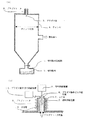
本発明は例えば図1(a)(b)に示す装置により実施することが出来る。図1(a)は装置全体の模式図、図1(b)はプラズマトーチを拡大した模式図である。
図1において、水冷管10により冷却されているプラズマトーチ8は、プラズマ動作ガス供給装置11によりプラズマ動作ガス供給位置6から供給されるプラズマ動作ガスと、コイル7から発生する高周波エネルギによりプラズマ炎3を発生する。
【0018】
原料供給装置1(例えば電磁振動原料供給装置)に投入された線材が一定の間隔で切断されてなる原料片は、キャリアガスと共に原料供給位置2よりプラズマ炎3内部の高温部(5000〜10000K)に投入される。プラズマ炎中に投入された原料片は瞬時に溶融し、表面張力により球状となる。
プラズマ炎内で処理された粉末はチャンバ4中を落下しながら不活性ガス雰囲気中で凝固し、球状粉末9として下部の球状粉末回収部5に集められ、回収される。
以上のようにして、球状粉末を効率的に製造することができる。
【0019】
【実施例】
図1に記載のRFプラズマ装置を用いて、Ag−Cu合金(不可避的不純物を含む)の金属片を用い、目標直径が80.0μmの球状粉末を以下に示す製造条件で作製した。プラズマ炎に導入するAg−Cu合金(原料片)は直径20μmのワイヤを回転刃により、一定寸法(長さ853μm)に切断して作製した。
【0020】
−製造条件(本発明例)−
原料片寸法:φ20μm×L853μm
プラズマ動作ガス:Ar 30L/min、H2 1L/min混合ガス(プラズマトーチ内の流速 0.26m/sec)
プラズマトーチ:水冷式石英管φ50mm、高周波誘導コイルφ70mm、図2(a)のプラズマトーチ
チャンバ:内径φ800mm、最大内高1500
チャンバ内雰囲気:Arガス雰囲気、大気圧
原料供給装置:電磁フィーダー
高周波誘導コイル入力条件:4MHz、8kW
【0021】
比較の為、図2(b)に記載のプラズマトーチを用い、下記のチャンバ内雰囲気条件を適用する以外は、上記の本発明例と同条件にて球状粉末を製造した。
−製造条件(比較例)−
チャンバ内雰囲気:Arガス雰囲気、0.03MPa
プラズマトーチ:水冷式石英管φ50mm、高周波誘導コイルφ70mm、図2(b)のプラズマトーチ
【0022】
プラズマ炎に導入後、球状粉末回収部に回収された球状粉末を、孔直径が75μmの丸孔篩と85μmの丸孔篩を用いて異形粉末の除去を行った。この結果、プラズマ導入前の原料片の重量と比較して、本発明例の製造方法では異形粉末の除去後には約83%の金属粉末を回収することが出来た。これに対し、比較例の製造方法では回収率は約3%であった。
丸孔篩により除去された異形粉末を確認したところ、目標とする80μmの球体とは体積や形状が著しく異なるものであった。これらは、プラズマ炎中で溶融した原料片同士が接触して体積、形状が変動したものと考えられる。
【0023】
次に、異形粉末を除去した後、無作為に100球を抽出し、平均直径、平均真球度を測定した。これらの測定は、平行透過光式で映し出した投影像をCCDカメラによる画像認識しておこなった。この際、直径は投影像を真円と仮定した場合の円相当径で、真球度は円相当径を最大径で除した値として評価した。結果を表1に示す。
【0024】
【表1】
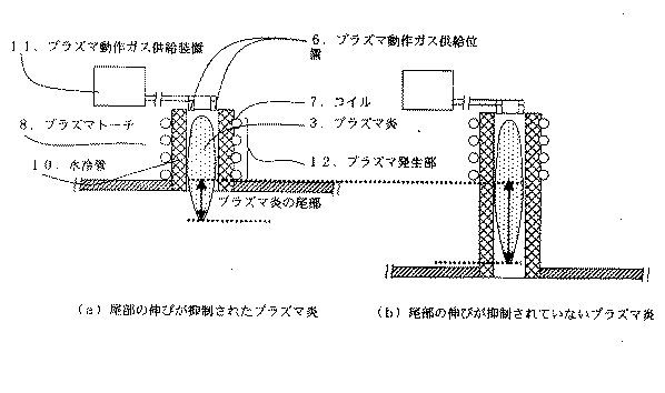
表1に示すように、本発明例では異形粉末除去後の球状粉末の最大値、最小値は、除去に用いた丸孔篩の直径、言いかえると除去後の粉末直径の上、下限値である75、85μmの幅より小さく、シャープな直径分布を達成している。目標直径である80μmに近い値となっており、本発明の製造方法では、異形粉末となった球状粉末以外では、プラズマ炎導入前後での体積変化が小さいことが分かる。また、異形粉末除去後の球状粉末は、真球度において0.996を達成しており、球状化を達成している。これに対し、比較例では、最大径、最小径がほぼ丸孔篩の直径と同程度であり、ばらつきが大きい。加えて真球度も本発明例と比べて低く、十分な球状化を達成できていない。
したがって、本発明の球状粉末の製造方法によれば粒度分布が狭く、形状の揃った球状粉末を生産することが出来ることが判る。
【0026】
【発明の効果】
本発明によれば、効率良く且つ極めてシャープな粒度分布をもつ球状粉末を形成することができる球状粉末の製造が可能となり、電子機器に使用される各種ろう材などの接続部材や、ガラス等からなるレンズやフィルター等、一定寸法の球状粉末を用いる分野において欠くことが出来ない技術となる。
【図面の簡単な説明】
【図1】本発明の製造方法を実施する製造装置の一例を示す模式図である。
【図2】プラズマ炎の尾部を示す模式図である。
【符号の説明】
1.原料供給装置、2.原料供給位置、3.プラズマ炎、4.チャンバ、5.球状粉末回収部、6.プラズマ動作ガス供給位置、7.コイル、8.プラズマトーチ、9.球状粉末、10.水冷管、11.プラズマ動作ガス供給装置、12.プラズマ発生部[0001]
TECHNICAL FIELD OF THE INVENTION
The present invention relates to a method for producing a spherical powder using plasma for producing a spherical powder having a certain size.
[0002]
[Prior art]
2. Description of the Related Art In recent years, as connection members used in electronic devices, various types of spherical powders such as solder, brazing material, gold, silver, and copper as terminals of a package have been used.
Also, ceramics such as glass use spherical powder of a certain size such as lenses and filters.
As a method for producing a spherical powder, a gas atomization method in which molten droplets solidify during flight has been widely used. However, although the gas atomization method has a spherical shape, it is difficult to efficiently obtain a sharp particle size because it is manufactured by spraying a liquid.
As another method, a method has been proposed in which a powder raw material is prepared in advance, and the raw material is put into a plasma flame to form a spheroid (see Patent Document 1).
[0003]
[Patent Document 1]
JP-A-6-287012 (page 3)
[0004]
[Problems to be solved by the invention]
As the technology for spheroidization in plasma flames mentioned above, attention has been paid to the control of residence time in plasma flames for melt spheroidization, and there is no method proposed to efficiently obtain spherical powder of a certain size at present. It is.
An object of the present invention is to provide a method for producing a spherical powder capable of efficiently forming a spherical powder having a very sharp particle size distribution.
[0005]
[Means for Solving the Problems]
In the spheroidization technology using a plasma flame, the present inventor has applied a raw material piece obtained by cutting a wire at a constant interval, and suppresses the elongation of the plasma flame, so that a spherical powder of a certain size can be efficiently agglomerated without agglomeration. The present invention was found to be able to be produced on a regular basis, and reached the present invention.
[0006]
That is, in the present invention, the raw material as a wire rod is cut at regular intervals into raw material pieces, and then, an aggregate of the raw material pieces is introduced into a plasma flame in which the elongation of the tail is suppressed, and is melted and spheroidized. This is a method for producing a spherical powder.
[0007]
In the present invention, preferably, the inner diameter of the plasma torch or the champer located at the outer periphery of the tail portion of the plasma flame is at least four times the inner diameter of the plasma torch of the plasma generating section. Preferably, the atmospheric pressure of the plasma is 0.04 Mpa to atmospheric pressure.
The volume of the raw material piece used in the present invention is preferably 20 to 1000 μm as a sphere equivalent diameter, and the melting point of the raw material powder is preferably 1600 ° C. or less.
[0008]
BEST MODE FOR CARRYING OUT THE INVENTION
As described above, one of the important features of the present invention resides in adopting a configuration in which an aggregate of raw material pieces obtained by cutting a raw material as a wire at a predetermined interval is introduced into a plasma flame. .
By cutting the wire rod uniformly, the individual volume of the raw material is determined. Ideally, if the raw material is spheroidized, a spherical powder having a constant diameter can be obtained. In actual production, it is extremely inefficient to feed raw material pieces one by one into a plasma flame. Therefore, in the present invention, first, it is required that the components be introduced collectively and continuously.
[0009]
In this case, a problem is a change in dimensions due to contact and agglomeration of the powder when introduced as an aggregate and evaporation in an extremely high temperature range of plasma.
The present invention has solved the above-mentioned problem by using a plasma flame which suppresses the extension of the tail of the flame, which is another feature. The tail portion of the plasma flame is a plasma portion where the plasma generated by the high frequency wave is extended by the flow of the operating gas, and indicates a downstream portion of the plasma from the high frequency coil.
[0010]
According to the study of the present inventor, since the temperature of the plasma itself is 5000 K or more, even if the raw material surface is continuously introduced as an aggregate, it reaches the melting temperature in a very short time. Furthermore, even if it deviates from the plasma flame, it is exposed to an atmosphere far exceeding the melting point of the raw material for a while. Therefore, when exposed to the plasma flame which is a high temperature region for a long time, the chance of contact between the powders in the molten state increases, and spheroidization is achieved, but the size increases, decreases, and evaporates due to the collision of the molten powders. It was confirmed that the particle size distribution was widened due to a decrease in volume and the like, and an ideal state of spheroidization according to the cut dimensions was not achieved.
[0011]
As a result of the study of the present inventor, after rapid heating by the plasma flame, it quickly escapes from the plasma flame, and spheroidizing in a gas that is not as hot as the plasma flame is effective because the particle size distribution is not expanded. It has been found that it is necessary to suppress the elongation of the tail portion of the plasma flame as a means thereof.
[0012]
As a specific method for suppressing the extension of the tail of the plasma flame, for example, it can be achieved by lowering the gas flow velocity at the tail of the plasma flame relative to the gas flow velocity of the plasma generation unit. In the simplest case, as shown in FIG. 2A, the inner diameter of the plasma torch or the champer located at the outer periphery of the tail of the plasma flame is set to be smaller than the inner diameter of the plasma torch of the plasma generator 11 with respect to the plasma generation direction. Increasing the size is an example. This makes it possible to reduce the gas flow velocity at the tail of the plasma flame and suppress the extension of the tail as compared with the case where it is not the case (FIG. 2B). The suppression of the elongation of the tail by the inner diameter of the plasma torch or the chamber is preferable because the effect becomes clear when the ratio of the inner diameter is 4 times or more.
[0013]
Further, in order to suppress the extension of the tail of the plasma flame, it is preferable to operate the plasma at a relatively high atmospheric pressure of 0.04 MPa to atmospheric pressure. At a pressure of less than 0.04 MPa, the plasma has a long tail, which makes it difficult to achieve the effects of the present invention, and there is a problem that it is difficult to control a plasma in a pressurized state exceeding atmospheric pressure. It is preferable to operate at a pressure of from .04 Mpa to atmospheric pressure.
[0014]
In addition to these methods, a method of mixing a gas having a high ionization energy such as H 2 or N 2 only in the tail portion of the plasma flame or an inert gas or the like is used, and this is blown from the outer periphery to the tail portion as a cooling gas. Also, the elongation of the plasma flame can be suppressed.
[0015]
More preferably, the above conditions are applied in combination. For example, the ratio of the inner diameter of the plasma torch or the chamber is four times or more, the atmospheric pressure of the plasma is 0.04 MPa to atmospheric pressure, and a gas having a high ionization energy such as H 2 or N 2 is mixed only in the tail of the plasma flame. It is more preferable to suppress the elongation of the tail portion of the plasma flame.
[0016]
Further, as a raw material piece applied to the present invention, if it is too large, it is difficult to form a sphere, and if it is too small, the volume change due to evaporation from the increase in surface area becomes large. It is preferable to apply to those having a thickness of 20 to 1000 μm.
Further, the present invention is preferably adapted to spheroidization of a material which is liable to evaporate in a plasma flame, and has a melting point of the raw material powder of 1600 ° C. or less, for example, solder, brazing material, gold, silver, copper It is effective to apply to glass and the like.
[0017]
The present invention can be carried out, for example, by an apparatus shown in FIGS. FIG. 1A is a schematic view of the entire apparatus, and FIG. 1B is an enlarged schematic view of a plasma torch.
In FIG. 1, a plasma torch 8 cooled by a water cooling tube 10 forms a
[0018]
A raw material piece obtained by cutting the wire rod supplied to the raw material supply device 1 (for example, an electromagnetic vibration raw material supply device) at a predetermined interval is a high temperature part (5000 to 10000K) inside the
The powder treated in the plasma flame solidifies in an inert gas atmosphere while falling in the chamber 4 and is collected as a spherical powder 9 in the lower spherical powder collecting section 5 and collected.
As described above, a spherical powder can be efficiently produced.
[0019]
【Example】
Using the RF plasma apparatus shown in FIG. 1, a spherical powder having a target diameter of 80.0 μm was produced under the following production conditions using a metal piece of an Ag—Cu alloy (including unavoidable impurities). The Ag-Cu alloy (raw material piece) to be introduced into the plasma flame was prepared by cutting a wire having a diameter of 20 µm into a certain size (length: 853 µm) with a rotary blade.
[0020]
-Manufacturing conditions (Example of the present invention)-
Raw material size: φ20μm × L853μm
Plasma operation gas: Ar 30 L / min, H 2 1 L / min mixed gas (flow rate in plasma torch 0.26 m / sec)
Plasma torch: water-cooled quartz tube φ50 mm, high frequency induction coil φ70 mm, plasma torch chamber in FIG. 2A: inner diameter φ800 mm, maximum inner height 1500
Chamber atmosphere: Ar gas atmosphere, atmospheric pressure material supply device: Electromagnetic feeder high frequency induction coil Input conditions: 4 MHz, 8 kW
[0021]
For comparison, a spherical powder was manufactured using the plasma torch shown in FIG. 2B under the same conditions as in the above-mentioned present invention example, except that the following atmosphere conditions in the chamber were applied.
-Manufacturing conditions (comparative example)-
Chamber atmosphere: Ar gas atmosphere, 0.03 MPa
Plasma torch: water-cooled quartz tube φ50 mm, high frequency induction coil φ70 mm, plasma torch in FIG. 2 (b)
After the introduction into the plasma flame, the spherical powder recovered in the spherical powder recovery section was subjected to removal of irregular shaped powder using a round hole sieve having a hole diameter of 75 μm and a round hole sieve having a hole diameter of 85 μm. As a result, compared with the weight of the raw material pieces before the introduction of the plasma, approximately 83% of the metal powder could be recovered after the removal of the irregularly shaped powder in the manufacturing method of the present invention. On the other hand, in the production method of the comparative example, the recovery was about 3%.
When the irregular-shaped powder removed by the round-hole sieve was confirmed, the volume and shape were remarkably different from the target 80 μm sphere. It is considered that the raw materials pieces melted in the plasma flame came into contact with each other and their volumes and shapes fluctuated.
[0023]
Next, after removing the irregularly shaped powder, 100 balls were randomly extracted, and the average diameter and the average sphericity were measured. These measurements were made by recognizing a projected image projected by a parallel transmitted light system using a CCD camera. At this time, the diameter was evaluated as a circle equivalent diameter assuming that the projected image was a perfect circle, and the sphericity was evaluated as a value obtained by dividing the circle equivalent diameter by the maximum diameter. Table 1 shows the results.
[0024]
[Table 1]
As shown in Table 1, in the examples of the present invention, the maximum value and the minimum value of the spherical powder after removal of the irregular-shaped powder are the diameter of the round hole sieve used for removal, in other words, the upper and lower limits of the diameter of the powder after removal. It is smaller than a certain width of 75 or 85 μm and achieves a sharp diameter distribution. The value is close to the target diameter of 80 μm, and it can be seen that in the production method of the present invention, the volume change before and after the introduction of the plasma flame is small except for the spherical powder which has become the irregularly shaped powder. In addition, the spherical powder from which the irregular-shaped powder has been removed has achieved a sphericity of 0.996, and has achieved spheroidization. On the other hand, in the comparative example, the maximum diameter and the minimum diameter are almost the same as the diameter of the round hole sieve, and the dispersion is large. In addition, the sphericity is lower than that of the examples of the present invention, and sufficient spheroidization cannot be achieved.
Therefore, it can be seen that according to the method for producing a spherical powder of the present invention, a spherical powder having a narrow particle size distribution and a uniform shape can be produced.
[0026]
【The invention's effect】
Advantageous Effects of Invention According to the present invention, it is possible to efficiently produce a spherical powder capable of forming a spherical powder having a very sharp particle size distribution. This technology is indispensable in the field of using spherical powder of a certain size, such as lenses and filters.
[Brief description of the drawings]
FIG. 1 is a schematic diagram illustrating an example of a manufacturing apparatus that performs a manufacturing method of the present invention.
FIG. 2 is a schematic view showing a tail portion of a plasma flame.
[Explanation of symbols]
1. Raw material supply device, 2. 2. Raw material supply position; 3. plasma flame; 4. chamber; 5. Spherical powder recovery section, 6. Plasma operation gas supply position; Coil, 8. 8. plasma torch, Spherical powder, 10. 10. water-cooled tube; 11. Plasma operating gas supply device, Plasma generator
Claims (5)
Priority Applications (1)
| Application Number | Priority Date | Filing Date | Title |
|---|---|---|---|
| JP2002293786A JP4239145B2 (en) | 2002-10-07 | 2002-10-07 | Method for producing spherical powder |
Applications Claiming Priority (1)
| Application Number | Priority Date | Filing Date | Title |
|---|---|---|---|
| JP2002293786A JP4239145B2 (en) | 2002-10-07 | 2002-10-07 | Method for producing spherical powder |
Publications (3)
| Publication Number | Publication Date |
|---|---|
| JP2004124231A true JP2004124231A (en) | 2004-04-22 |
| JP2004124231A5 JP2004124231A5 (en) | 2005-11-10 |
| JP4239145B2 JP4239145B2 (en) | 2009-03-18 |
Family
ID=32284594
Family Applications (1)
| Application Number | Title | Priority Date | Filing Date |
|---|---|---|---|
| JP2002293786A Expired - Fee Related JP4239145B2 (en) | 2002-10-07 | 2002-10-07 | Method for producing spherical powder |
Country Status (1)
| Country | Link |
|---|---|
| JP (1) | JP4239145B2 (en) |
Cited By (8)
| Publication number | Priority date | Publication date | Assignee | Title |
|---|---|---|---|---|
| KR100840229B1 (en) | 2006-09-08 | 2008-06-23 | 재단법인 포항산업과학연구원 | Ultra fine solder powder, ultra fine solder powder manufacturing method and manufacturing apparatus |
| CN102672189A (en) * | 2012-05-17 | 2012-09-19 | 赣州海盛钨钼集团有限公司 | Preparation method of spherical tungsten powder |
| CN106001594A (en) * | 2016-07-15 | 2016-10-12 | 北京科技大学 | Preparation method for ultra-coarse spherical tungsten powder |
| US9533909B2 (en) | 2014-03-31 | 2017-01-03 | Corning Incorporated | Methods and apparatus for material processing using atmospheric thermal plasma reactor |
| US9550694B2 (en) | 2014-03-31 | 2017-01-24 | Corning Incorporated | Methods and apparatus for material processing using plasma thermal source |
| US10059614B2 (en) | 2013-10-04 | 2018-08-28 | Corning Incorporated | Melting glass materials using RF plasma |
| US10167220B2 (en) | 2015-01-08 | 2019-01-01 | Corning Incorporated | Method and apparatus for adding thermal energy to a glass melt |
| WO2025077064A1 (en) * | 2023-10-12 | 2025-04-17 | 浙江大学衢州研究院 | Preparation system and preparation method for spherical micro-nano powder |
-
2002
- 2002-10-07 JP JP2002293786A patent/JP4239145B2/en not_active Expired - Fee Related
Cited By (10)
| Publication number | Priority date | Publication date | Assignee | Title |
|---|---|---|---|---|
| KR100840229B1 (en) | 2006-09-08 | 2008-06-23 | 재단법인 포항산업과학연구원 | Ultra fine solder powder, ultra fine solder powder manufacturing method and manufacturing apparatus |
| CN102672189A (en) * | 2012-05-17 | 2012-09-19 | 赣州海盛钨钼集团有限公司 | Preparation method of spherical tungsten powder |
| US10059614B2 (en) | 2013-10-04 | 2018-08-28 | Corning Incorporated | Melting glass materials using RF plasma |
| US9533909B2 (en) | 2014-03-31 | 2017-01-03 | Corning Incorporated | Methods and apparatus for material processing using atmospheric thermal plasma reactor |
| US9550694B2 (en) | 2014-03-31 | 2017-01-24 | Corning Incorporated | Methods and apparatus for material processing using plasma thermal source |
| JP2017518244A (en) * | 2014-03-31 | 2017-07-06 | コーニング インコーポレイテッド | Material processing method and apparatus using atmospheric pressure thermal plasma reactor |
| US9908804B2 (en) | 2014-03-31 | 2018-03-06 | Corning Incorporated | Methods and apparatus for material processing using atmospheric thermal plasma reactor |
| US10167220B2 (en) | 2015-01-08 | 2019-01-01 | Corning Incorporated | Method and apparatus for adding thermal energy to a glass melt |
| CN106001594A (en) * | 2016-07-15 | 2016-10-12 | 北京科技大学 | Preparation method for ultra-coarse spherical tungsten powder |
| WO2025077064A1 (en) * | 2023-10-12 | 2025-04-17 | 浙江大学衢州研究院 | Preparation system and preparation method for spherical micro-nano powder |
Also Published As
| Publication number | Publication date |
|---|---|
| JP4239145B2 (en) | 2009-03-18 |
Similar Documents
| Publication | Publication Date | Title |
|---|---|---|
| CN104607823B (en) | A kind of manufacture method of spherical self-melting alloy solder | |
| CN104259469B (en) | The manufacture method of micron and the spherical powder of nano metal | |
| JP7568700B2 (en) | Low melting point metal or alloy powder atomization manufacturing process | |
| KR20200084887A (en) | Method and apparatus for producing fine spherical powder from coarse and angled powder feed material | |
| CN105397100B (en) | A kind of preparation method of refining metallic powder and the equipment for realizing this method | |
| TW201720550A (en) | Equipment and method of manufacturing alloy powder can heat an alloy raw material stick to obtain column-like alloy melt soup to cool and mist melt soup so as to form alloy powder | |
| JPS63243211A (en) | Wet metallurgical method for producing finely divided globular noble metal base powder | |
| JP2011098348A (en) | Method and apparatus for producing fine particle | |
| JP2002346377A (en) | Method and apparatus for producing ceramic or metal spherical powder by thermal plasma | |
| JPH01263204A (en) | Low oxygen content fine globular particles and production thereof by fluid energy milling and high temperature treatment | |
| JP4239145B2 (en) | Method for producing spherical powder | |
| CN110919014A (en) | Preparation method of titanium alloy powder for 3D printing | |
| CN106216702A (en) | A kind of spherical titanium or the preparation method of Titanium Powder | |
| JP2005161338A (en) | Solder sheet | |
| JP2004091843A (en) | Manufacturing method of high purity high melting point metal powder | |
| JP2001064703A (en) | Production of fine spherical metal powder | |
| JP3270118B2 (en) | Method and apparatus for producing spheroidized particles by high-frequency plasma | |
| JP4789198B2 (en) | Lead-free solder alloy | |
| EP0134808B1 (en) | Method for making ultrafine metal powder | |
| JP7328796B2 (en) | METHOD AND APPARATUS FOR MANUFACTURING METAL POWDER | |
| JPS63111101A (en) | Spheroidizing method for metal or alloy powder | |
| JPH0426701A (en) | Manufacture of fine gold ball | |
| JP2017155279A (en) | Method for producing metal fine particles | |
| JP3925792B2 (en) | Method for producing metal sphere for conductive spacer | |
| JP2006009113A (en) | Method for producing fine metal ball |
Legal Events
| Date | Code | Title | Description |
|---|---|---|---|
| A521 | Written amendment |
Free format text: JAPANESE INTERMEDIATE CODE: A523 Effective date: 20050920 |
|
| A621 | Written request for application examination |
Free format text: JAPANESE INTERMEDIATE CODE: A621 Effective date: 20050920 |
|
| A977 | Report on retrieval |
Free format text: JAPANESE INTERMEDIATE CODE: A971007 Effective date: 20070521 |
|
| A131 | Notification of reasons for refusal |
Free format text: JAPANESE INTERMEDIATE CODE: A131 Effective date: 20070622 |
|
| A02 | Decision of refusal |
Free format text: JAPANESE INTERMEDIATE CODE: A02 Effective date: 20080516 |
|
| A521 | Written amendment |
Free format text: JAPANESE INTERMEDIATE CODE: A523 Effective date: 20080711 |
|
| A911 | Transfer of reconsideration by examiner before appeal (zenchi) |
Free format text: JAPANESE INTERMEDIATE CODE: A911 Effective date: 20080804 |
|
| TRDD | Decision of grant or rejection written | ||
| A01 | Written decision to grant a patent or to grant a registration (utility model) |
Free format text: JAPANESE INTERMEDIATE CODE: A01 Effective date: 20081128 |
|
| A01 | Written decision to grant a patent or to grant a registration (utility model) |
Free format text: JAPANESE INTERMEDIATE CODE: A01 |
|
| A61 | First payment of annual fees (during grant procedure) |
Free format text: JAPANESE INTERMEDIATE CODE: A61 Effective date: 20081211 |
|
| FPAY | Renewal fee payment (event date is renewal date of database) |
Free format text: PAYMENT UNTIL: 20120109 Year of fee payment: 3 |
|
| R150 | Certificate of patent or registration of utility model |
Free format text: JAPANESE INTERMEDIATE CODE: R150 |
|
| FPAY | Renewal fee payment (event date is renewal date of database) |
Free format text: PAYMENT UNTIL: 20130109 Year of fee payment: 4 |
|
| FPAY | Renewal fee payment (event date is renewal date of database) |
Free format text: PAYMENT UNTIL: 20130109 Year of fee payment: 4 |
|
| LAPS | Cancellation because of no payment of annual fees |