JP2004124792A - Oil supply path for 4-cycle engine - Google Patents
Oil supply path for 4-cycle engine Download PDFInfo
- Publication number
- JP2004124792A JP2004124792A JP2002288917A JP2002288917A JP2004124792A JP 2004124792 A JP2004124792 A JP 2004124792A JP 2002288917 A JP2002288917 A JP 2002288917A JP 2002288917 A JP2002288917 A JP 2002288917A JP 2004124792 A JP2004124792 A JP 2004124792A
- Authority
- JP
- Japan
- Prior art keywords
- oil
- oil passage
- crankcase
- chamber
- crankshaft
- Prior art date
- Legal status (The legal status is an assumption and is not a legal conclusion. Google has not performed a legal analysis and makes no representation as to the accuracy of the status listed.)
- Granted
Links
Images
Landscapes
- Cylinder Crankcases Of Internal Combustion Engines (AREA)
- Lubrication Of Internal Combustion Engines (AREA)
Abstract
Description
【0001】
【発明の属する技術分野】
本願発明は、オートバイあるいは騎乗型の不整地走行用四輪車等の車輌に適した4サイクルエンジンのオイル供給経路に関する。
【0002】
【従来の技術】
4サイクルエンジンには、通常、オイルポンプが備えられると共に該オイルポンプから各注油個所に至るオイル供給経路が設けられており、注油個所としては、クランク軸周り、コンロッド、ピストン周り、シリンダヘッド上の動弁カム機構、ミッションギヤ及びクラッチ等が該当する(たとえば特許文献1参照)。
【0003】
エンジン内に分布する上記各注油個所に対して、1個所のオイルポンプから効率良くオイルを供給するために、オイル供給経路中に、クランクケースのクランク軸芯方向の一方側から他方側に亘るオイル通路を設ける場合がある。
【0004】
このようにクランクケースのクランク軸芯方向の一方側と他方側を連通するオイル通路の構造としては、従来、パイプやチューブ等をエンジンの外部に配管してなる外部配管構造、あるいはクランクケースの壁内に直接オイル通路を形成する構造等が採用されている。
【0005】
クランクケース壁内に直接オイル通路を形成する構造の例として、たとえば図12に示すように、クランク軸芯O1方向に見て、クラッチカバー合面上のクラッチ200と重ならない位置に、シリンダ201から離れたミッション上方までオイル通路202を形成し、該オイル通路202に、クラッチ室からミッション室を貫通する横断型オイル通路203を形成しているエンジンがある。
【0006】
なお、本件特許出願人は、本願発明に関連するクランクケース横断型のオイル通路について特許文献を調査したが、関連の深いと思われる特許文献は発見できなかった。
【0007】
【特許文献1】実公平2−48657号公報。
【0008】
【発明が解決しようとする課題】
前者の外部配管構造では、チューブや継手管等の配管部品が増加して、コストが高くなると共に組立工数も増加する。
【0009】
図12に対応するクランクケース壁内形成構造では、クランクケースが大型化し、重量も増加する。
【0010】
【発明の目的】
本願発明の目的は、クランクケース内のデッドスペースを有効に利用して、クランクケースをクランク軸芯方向に横断する横断型のオイル通路を形成することにより、クランクケースのコンパクト性を維持し、かつ、製造及び組付の容易性を確保できる4サイクルエンジンのオイル供給経路を提供することである。
【0011】
また、ピストンの内面を、専用配管を施すことなく、強制冷却できるようにすることも目的としている。
【0012】
【課題を解決するための手段】
上記課題を解決するために本願請求項1記載の発明は、エンジン内の各注油個所にオイルを圧送する4サイクルエンジンのオイル供給経路において、クランク軸芯方向に見て、コンロッド軌跡とクランクウエブ軌跡と下死点のピストンのスカート後端部又はスカート前端部で囲まれた範囲内に位置すると共に、シリンダ中心線方向に見てボア範囲内を通過するように、クランクケース内をクランク軸芯方向と略平行に横断する筒状のオイル通路形成部材を配置していることを特徴としている。
【0013】
上記構成によると、クランクケース内のデッドスペースを有効に利用してクランクケース横断型オイル通路形成部材を配置しているので、クランクケースの大型化を防ぐことができる。また、オイル通路形成部材はクランクケースの左右側壁の補強リブの役目を果たし、剛性も向上する。
【0014】
請求項2記載の発明は、請求項1記載の4サイクルエンジンのオイル供給経路において、オイル通路形成部材の途中には、ピストンの頂壁の下面に向いて開口するオイル噴出口を形成してあること特徴としている。
【0015】
上記構成によると、ピストンの内面冷却専用の配管あるいはオイル通路を形成することなく、ピストンの内面を冷却でき、低コストでピストンの冷却効果を向上させることができる。
【0016】
請求項3記載の発明は、請求項1又は2記載の4サイクルエンジンのオイル供給経路において、オイル通路形成部材は、左右割り構造のクランクケースの左右各クランクケース部材に分割形成し、左右のクランクケース部材の結合により、左右の両オイル通路形成部材の先端面同士を突き合わせ接続していることを特徴としている。
【0017】
上記構成によると、クランクケース横断型オイル通路形成部材の製造及び組付が簡単である。
【0018】
【発明の実施の形態】
図1〜図10は、本願発明が適用されたドライサンプ式単気筒4サイクルエンジンであり、たとえばモトクロス用オートバイに搭載されており、これら図面に基づいて本願発明の一実施の形態を説明する。なお、説明の都合上、クランク軸芯方向を左右方向として説明する。
【0019】
[クランク室、ミッション室及びオイルタンク室]
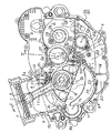
図1はクランク軸芯O1と直角で、シリンダ中心線Cを含む面で切断したクランクケース2の右半分の内部を示す縦断側面図である。この図1において、クランクケース2内は、前部にクランク軸1を収納するクランク室4が形成され、後部がギヤ式ミッションを収納するミッション室5が形成され、ミッション室5の下部はオイルタンク室9となっている。
【0020】
クランク室4の上面にはシリンダ6が締着され、該シリンダ6の上側には図示しないが周知のようにシリンダヘッド及びヘッドカバー(ロッカーアームカバー)等が順次締着されており、シリンダ6のボア7に嵌合するピストン8は、ピストンピン10及びコンロッド11を介してクランク軸1のクランクピン12に連結している。
【0021】
クランク室4とミッション室5の間には、一定高さの仕切り壁16がクランクケース2と一体に形成されており、該仕切り壁16により、オイルタンク室9をクランク室4から隔離している。
【0022】
上記仕切り壁16は、クランク軸芯O1より若干高く形成されると共に、クランクウエブ17の回転軌跡に沿って円弧状に前下方に延び、クランクウエブ17の回転軌跡の下側で、下方に延びる隔壁18に繋がっており、これによりオイルタンク室9をクランク室4の後半部の下方位置まで拡張している。
【0023】
クランク室4の下側にはクランクウエブ17の回転軌跡に沿って底壁20が形成されており、この底壁20と、前記隔壁18と、クランクケース2の下端壁により、スカベンジングポンプ用のオイル吸込室22を形成している。上記底壁20の後端部には、クランク室4のオイルをオイル吸込室22に排出するために、後下方に向いて開口する排出孔23が形成されている。
【0024】
ミッション室5内には、クランク軸芯O1よりも上方位置に変速入力軸27と変速出力軸28が前後に間隔を置いて並行配置され、クランク軸芯O1よりも下方位置であって、前記変速入力軸27と変速出力軸28との前後方向間にチェンジドラム30が配置され、チェンジドラム30の後下方にチェンジペダルに連結するチェンジ軸31が配置されている。O2,O3,O4,O5はそれぞれ変速入力軸芯、変速出力軸芯、チェンジドラム軸芯、チェンジ軸芯を示している。また、クランクケース前端部のO7はバランサ軸芯を示している。
【0025】
オイルタンク室9にはエンジン運転時において油面L1までオイルが貯留されており、この油面L1の高さは、概ねクランク軸O1程度の高さであって、変速ギヤ群がオイルに漬からない高さに維持されている。
【0026】
[クランク軸]
図2は図1のII−II断面展開図であり、クランクケース2は左右2つ割り構造となっており、シリンダ中心線Cを含みクランク軸芯O1と直角な面を合わせ面として、左右のクランクケース部材2a,2bを結合することにより構成されている。
【0027】
クランクケース2の左右の側壁34,35には、それぞれクランク軸支持孔41,42が形成され、各クランク軸支持孔41,42にはそれぞれ主軸受37,38が嵌着され、両主軸受37,38によりクランク軸1を両持ち支持している。
【0028】
クランク軸1の右端部は右側主軸受38を貫通して右側のクラッチ室44内に突出し、該突出部分には右側から車輪駆動用の一次ギヤ(クランクギヤ)46が固定されると共にポンプ駆動用のチェーンスプロケット47がクランク軸1と一体に形成されている。
【0029】
クランク軸1の左端部は左側主軸受37を貫通して左側のジェネレータ室45に突出し、先端テーパー部にはジェネレータのロータ部48が固定され、該ロータ部48と左側主軸受37の間には、カムチェーンスプロケット50が一体に形成されると共に、バランサ駆動ギヤ51が固定されている。上記カムチェーンスプロケット50に巻き掛けられたカムチェーン49は、カムチェーントンネル74を通って図示しないシリンダヘッドに至り、弁駆動用カム軸のスプロケットに連動連結している。
【0030】
クランク軸1内には、右端からクランクピン12まで至るオイル通路52が形成されている。
【0031】
[ミッション]
ミッション室5内の変速入力軸27は、左右のクランクケース側壁34,35の軸支持孔に嵌着された軸受55,56により両持ち支持されており、変速入力軸27上には、左から順に2速用ギヤ58、4速用ギヤ59、3速用ギヤ60、5速用ギヤ61及び1速用ギヤ62が設けられており、これらの変速ギヤ群は図示しないが変速出力軸側の変速ギヤに噛み合っている。変速入力軸27の右端部はクラッチ室44に突出し、該突出部には多板式摩擦クラッチ65が装着され、該摩擦クラッチ65のクラッチギヤ66は前記クランク軸1の一次ギヤ46に噛み合っている。また、クラッチギヤ66には始動用ギヤ67が一体成形されている。
【0032】
変速入力軸27内には左端のオイル室70に連通するオイル通路71が形成され、該オイル通路71は、たとえば4速用59ギヤ及び5速ギヤ61の嵌合部並びにクラッチギヤ66の嵌合部等に連通している。
【0033】
[ポンプ構造]
図2において、該エンジンは、各注油個所からの戻りオイルをオイルタンク室側へ汲み上げるスカベンジングポンプ77と、エンジン内の各注油個所にオイルを圧送するフィードポンプ78との2つのオイルポンプを備えており、両ポンプ77,78はクランク軸芯O1方向の両側、すなわち左右両側に振分け配置され、クランクケース左側壁34内と、クランクケース右側壁35内にそれぞれ設けられている。該実施の形態では、ジェネレータ配置側のクランクケース左側壁34にスカベンジングポンプ77を、クラッチ配置側のクランクケース右側壁35にフィードポンプ78を配置してある。
【0034】
いずれのポンプ77,78も、ポンプハウジング77a,78a内に内外一対のロータ77b,78bを噛み合い状態で回転可能に収納してなるトロコイド型ポンプであり、各ポンプハウジング77a,78aは各クランクケース側壁34,35にそれぞれ一体成形されており、各ポンプハウジング77a,78aの前端縁は、クランクウエブ17の回転軌跡の後端に概ね対応する位置に形成されている。すなわち、各ポンプ77,78は、クランクウエブ17の回転軌跡の範囲外であって、その直後に位置している。
【0035】
各ポンプハウジング77a,78aのクランク軸芯方向の端面には、それぞれポンプカバー80,81が締着されている。左側のスカベンジングポンプ77は右側のフィードポンプ78よりも吐出容量の大きいポンプであり、そのため、スカベンジングポンプ77のロータ77bの左右幅(軸方向幅)は、フィードポンプ78のロータ78bの左右幅よりも大きく、略2倍程度となっている。また、スカベンジングポンプ77は、変速入力軸27上で、2番目に径の小さい2速用ギヤ58に対応する位置に位置し、フィードポンプ78は最も径の小さい1速用ギヤ62に対応する位置に配置しており、これらにより、ポンプ軸O6と変速入力軸芯O2の間隔を無駄に広く採る必要がなく、径方向のコンパクト性も保つことができる。
【0036】
各ロータ77b,78bが固定されたポンプ軸82,83は、クランク軸芯O1と平行で仕切り壁16の直後に位置すると共に、同一のポンプ軸芯O6上に揃えられ、オルダム継手91を介して連動連結している。
【0037】
右側のフィードポンプ軸83は右側のクラッチ室44内に突出しており、該突出部分には、ポンプカバー81とクラッチギヤ66の間に位置するチェーンスプロケット85が固着され、該チェーンスプロケット85はチェーン86によりクランク軸1のポンプ駆動用チェーンスプロケット47に連動連結している。
【0038】
[クラッチ室等]
図3は右側クランクケース部材2bの外面(右側面)であって、クラッチ室44内を示しており、フィードポンプ78はそのポンプカバー81(図2)を取り外した状態で示してある。クランクケース2の下端部は車輌フレームのロアパイプP間に位置するように配置されている。フィードポンプ78のポンプ軸芯O6は、変速入力軸芯(クラッチ軸芯)O2の略直下位置であって、クランク軸芯O1と概ね同じ高さに位置しており、フィードポンプ78のハウジング部78aは、クランク軸芯O1方向)に見て、摩擦クラッチ65の範囲内に納められている。すなわち、側方から見て摩擦クラッチ65と重なっている。
【0039】
フィードポンプ78の吸込口122には、図1に仮想線で示すようにミッション室5内を後下方に延びてオイルタンク室9の下端部に至る吸込管123が接続しており、該吸込管123には二次フィルタが内蔵されている。
【0040】
図3において、フィードポンプ78の下端吐出口129には、前下方に延びる吐出側オイル通路89が連通しており、該吐出側オイル通路89はクランクケース右側壁35及びポンプカバー81(図2)により形成されている。吐出側オイル通路89は、途中でリリーフ用オイル通路90が分岐し、該リリーフ用オイル通路90は、ポンプカバー81(図2)に設けられたリリーフ弁92を介してクラッチ室44内に連通し、リリーフされたオイルをクラッチ室44内に排出するようになっている。
【0041】
クラッチ室44の前部であって、クランク軸芯O1とバランサ軸芯O7との前後方向間に対応する位置には、クラッチ室下端面から一定高さH2のオーバーフロー孔69が形成されており、該オーバーフロー孔69は図1のようにクランク室4の底面に連通している。該オーバーフロー孔69からクランク室4へオイルを溢出させることにより、図3のクラッチ室44内のオイルを油面L2に維持するようになっている。油面L2は、具体的にはクラッチ65が漬からない程度に設定されている。したがって、前記のようにクラッチ65と側方から見て重なる位置にフィードポンプ78等を配置している場合には、図2のポンプ駆動用のチェーンスプロケット85並びにクランク軸1のポンプ駆動用チェーンスプロケット47は、クラッチ室44内でオイルに漬からない高さに位置している。
【0042】
図4はクラッチカバー14をクランクケース2の右側面に締着した状態を示す側面図であり、クラッチカバー14の後半部には、クラッチの外形に対応した大きな円形の窓孔が形成され、該窓孔には円形の点検カバー93が着脱自在に締着され、点検カバー93の前側には三次フィルタ収納凹部94が形成され、該三次フィルタ収納凹部94の前側には水ポンプのハウジング95が一体に形成されている。
【0043】
[オイル供給及び横断型オイル通路に関する構造]
クラッチカバー14の下端部には、前記フィードポンプ吐出側オイル通路89の下端部に連通するオイル通路97が形成され、該オイル通路97は前上方に延びると共に略垂直上方に折れ曲がり、前記三次フィルタ収納凹部94のフィルタ入口に至っている。
【0044】
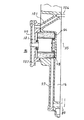
図7は図4のVII−VII断面拡大図であり、三次フィルタ収納凹部94には三次フィルタ98が収納されると共に凹部カバー99が着脱自在に取り付けられており、該凹部カバー99内には、三次フィルタ98の出口に連通して上下に分岐するオイル通路101,102が形成されている。
【0045】
上方に延びるオイル通路101は、再びクラッチカバー14のオイル通路103に連通し、該オイル通路103はクランクケース右側壁35に形成されたオイル通路104に連通している。
【0046】
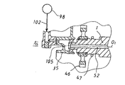
図8は図4のVIII−VIII断面拡大図であり、前記三次フィルタ98から下方に延びるオイル通路102は、クランク軸1の右端部まで至り、クランクケース右側壁35に形成されたオイル室105を介してクランク軸1内のオイル通路52に連通している。
【0047】
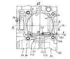
図9はクランク室4を上方から見た平面図であり、前記クラッチカバー14のオイル通路103に連通するクランクケース右側壁35内のオイル通路104は、クランク室4を左右(クランク軸芯方向)に貫通する横断型のオイル通路管(オイル通路形成部材)110内のオイル通路111に連通している。
【0048】
上記オイル通路管110は、クランク軸芯O1と平行に延びると共にシリンダ6のボア7の範囲内を通過しており、左右のクランクケース部材2a,2bの合わせ面を境として、左右に分割形成されている。すなわち、オイル通路管110の左側半分はクランクケース左側壁34に一体成形され、オイル通路管110の右側半分はクランクケース右側壁35に一体成形され、左右のオイル通路管110は突き合せ状態で接続している。
【0049】
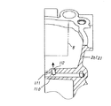
図10は図9のX−X断面拡大図であり、右側のオイル通路管110の途中には、前上方に向いて開口するオイル噴出口112が形成されている。上記オイル通路管110は、図1において、クランク軸芯方向に見て、クランクウエブ17の軌跡と、コンロッド11の軌跡と、仮想線で示すように下死点位置におけるピストン8のスカート後端部8aとで囲まれた空間(範囲)に配置されている。さらに、オイル噴出口112は、矢印Kのように、下死点位置のピストン8に対してはピストンピン10より後方部位に向いているが、上死点位置のピストン8に対してはピストンピン10よりも前方部位に向く角度で形成されている。
【0050】
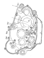
図5は左側クランクケース部材2aの内面(右側面)図であり、前記オイル通路管110のオイル通路111は、クランクケース左側壁34内を上方に延びるシリンダヘッド周り用のオイル通路120と、後方に延びるミッション用のオイル通路121に分岐している。
【0051】
上方に延びるオイル通路120は、図示しないがシリンダ6内のオイル通路及びシリンダヘッド内のオイル通路を経て、弁駆動用のカム機構に至っている。後方に延びるミッション用のオイル通路121は、クランクケース左側壁34に形成された変速入力軸用のオイル室70及び変速出力軸用のオイル室72に至っている。
【0052】
[オイルの戻りに関する構造]
図6は左側クランクケース部材2aの外面(左側面)であって、ジェネレータ室45内を示しており、スカベンジングポンプ77はポンプカバー80(図2)を取り外して示してある。スカベンジングポンプ77のハウジング部77aの前下端に吸込口124が形成され、該吸込口124には、前下方に延びる吸込側オイル通路131が連通し、該吸込側オイル通路131は、クランクケース左側壁34及びポンプカバー80(図2)により形成されており、板状の一次フィルタ132を介してジェネレータ室下端のスカベンジング用吸込通路125に連通している。この吸込通路125は、ジェネレータ室45とは隔離されており、スカベンジングポンプ77の吸込圧が作用する状態となっている。
【0053】
上記スカベンジング用吸込通路125の前側には、ジェネレータ室45からオイルを排出するための排出孔126が形成されており、該排出孔126と上記スカベンジング用吸込通路125は、図5に示すようにクランク室4の下側に形成された前記オイル吸込室22に連通している。
【0054】
すなわち、オイル吸込室22には、ジェネレータ室側から排出孔126を経て流入するオイルと、クランク室4から後端排出孔23を経て流入するオイルが集まり、スカベンジングポンプ用吸込通路125からスカベンジングポンプ77に吸い込まれるようになっている。また、図6のジェネレータ室45の一部のオイルは、排出孔25を通って一旦図5のクランク室4に入り、上記同様にクランク室4の後端排出孔23からオイル吸込室22に排出されるようになっている。
【0055】
スカベンジングポンプ77の吐出口136は、仕切り壁16の上端部の直後に形成され、ミッション室5内に向いて開口している。該吐出口136の上側には、変速ギヤ群にオイルがかからないように円弧状の庇137が一体に形成されている。
【0056】
【作用】
[ポンプの駆動]
図2において、クランク軸1の回転は、クランク軸1のポンプ駆動用チェーンスプロケット47、チェーン86及びチェーンスプロケット85を介してフィードポンプ軸83に伝達され、フィードポンプ78を駆動する。
【0057】
さらにフィードポンプ軸83から直接スカベンジングポンプ軸82に伝達され、スカベンジングポンプ77を駆動する。
【0058】
前記両チェーンスプロケット47,85はクラッチ室44内に配置されているが、図3に示すクラッチ室44の油面L2よりも高く配置されているため、オイルの抵抗による動力損失が発生せず、高い動力伝達効率が保たれる。
【0059】
[各注油個所へのオイルの流れ]
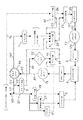
(1)図11はエンジン内のオイル循環を簡単にまとめたブロック図であり、該図11により、エンジン運転中のオイル循環を説明する。オイルタンク室9から二次フィルタを介してフィードポンプ78に吸い込まれたオイルは、クランクケース右側壁内のオイル通路89及びクラッチカバー内のオイル通路97等を経て三次フィルタ98内に入る。上記オイル通路89の途中において、一部のオイルはリリーフ用オイル通路90及びリリーフバルブ92を経てクラッチ室44に逃がされる。
【0060】
(2)上記三次フィルタ98でろ過されたオイルは2つのオイル通路101,102に分かれ、一方のオイル通路102に供給されたオイルはクランク軸1に至り、クランクピン等のクランク軸周りを潤滑する。
【0061】
(3)他方のオイル通路101に供給されたオイルは、クランク室内を横切る横断型のオイル通路111を経てクランクケース左側壁内に至るが、上記オイル通路111の途中でオイル噴出口112からピストン内面に向ってオイルの一部が噴出され、ピストン内面を強制冷却する。この場合、図1において、オイル噴出口112から前上方(K方向)に向いてオイルが噴出され、該噴出オイルは、ピストン8が下死点まで下降した状態では、ピストン8の頂壁の後半部(ピストンピンより後側)に吹きつけられ、ピストン内面の後半部を主に冷却する。そして、ピストン8が上昇するに従い、吹付け個所は前方に移動し、ピストン内面の略全面を冷却する。
【0062】
(4)オイル通路111内を通ってクランクケース左側壁に至ったオイルは、ここでさらに2つのオイル通路120,121に分けて供給され、一方のオイル通路121に供給されたオイルは、変速入力軸27及び変速出力軸28並びにクラッチ65に至り、各変速ギヤの嵌合部分並びにクラッチ65を潤滑する。他方のオイル通路120に供給されたオイルは、シリンダヘッド周りのカム軸等に至る。
【0063】
[各注油個所からのオイルの戻り]
(1)変速入力軸27及び変速出力軸28の潤滑に利用されたオイルは、ミッション室5を介して下方のオイルタンク室9に直接落下又は流下する。クラッチ65の潤滑及び冷却に利用されたオイルは、クラッチ室44に落下又は流下する。
【0064】
(2)クラッチ室44のオーバーフロー孔69から溢出したオイルはクランク室4に流れる。
【0065】
(3)クランク軸1周りの潤滑に利用されたオイルと、ピストン8の内面の冷却に利用されたオイルは、クランク室4の底面に落下あるいは流下し、クランク室4内で前記クラッチ室44等からのオイルと合流し、底壁後端排出孔23からオイル吸込室22に排出される。
【0066】
(4)シリンダヘッド周り及びカム軸等の潤滑に利用されたオイルは、カムチェーントンネル74を通ってジェネレータ室45に落下又は流下し、下端排出孔126を通ってオイル吸込室22に排出されるが、ジェネレータ室45内の一部のオイルは、排出孔25、クランク室4及び後端排出孔23を通ってオイル吸込室22に排出される。したがってジェネレータ室45にはオイルは殆ど溜まることはない。
【0067】
(5)上記のようにシリンダヘッド周り、カム軸、クランク軸1、ピストン8からの戻りオイルはオイル吸込室22に集められ、スカベンジング用吸込通路125から一次フィルタ132及び吸込側オイル通路131を経てスカベンジングポンプ77に吸い込まれ、吐出口136からミッション室5に放出され、オイルタンク室9に戻される。
【0068】
【その他の発明の実施の形態】
(1)前記実施の形態では、横断型オイル通路111の噴出口112は一箇所のみ形成してあるが、複数個所に形成することも可能であり、その場合には、水平に対する傾斜角度を異ならせることにより、ピストンに対して広範囲にオイルを吹き付けるようにすることができる。
【0069】
(2)横断型オイル通路形成部材の配置位置としては、前記実施の形態では、図1においてコンロッドの軌跡とクランクウエブの軌跡の後側で、下死点位置のピストン8のスカート後端部8aで囲まれた位置であるが、図1のコンロッド11の軌跡とクランクウエブ17の軌跡の前側であって、上記両軌跡と下死点位置のピストン8のスカート前端部8bで囲まれる位置(たとえばA1)に形成することも可能である。
【0070】
(3)横断型オイル通路形成部材を、クランクケースとは別体のパイプ部材で構成することも可能である。
【0071】
【発明の効果】
以上説明したように本願発明によると、(1)クランク軸芯方向に見て、コンロッド軌跡とクランクウエブ軌跡と下死点のピストンのスカート後端部又はスカート前端部で囲まれた範囲内に位置すると共に、シリンダ中心線方向に見てボア範囲内を通過するように、クランクケース内をクランク軸芯方向と略平行に横断する筒状のオイル通路形成部材を配置しているので、クランクケース内のデッドスペースをオイル通路配置用に有効に利用することができ、クランクケースの大型化を防ぐことができる。また、オイル通路形成部材は、クランクケースの左右側壁の補強リブの役目を果たし、クランクケースの剛性が向上する。
【0072】
(2)オイル通路形成部材の途中に、ピストンの頂壁の下面に向いて開口するオイル噴出口を形成してあると、ピストンの内面冷却専用の配管あるいはオイル通路を形成することなく、ピストンの内面を冷却でき、低コストでピストンの冷却効果を向上させることができる。
【0073】
(3)オイル通路形成部材を、左右割り構造のクランクケースの左右各クランクケース部材に分割形成し、左右のクランクケース部材の結合により、左右の両オイル通路形成部材の先端面同士を突き合わせ接続していると、横断型オイル通路の製造及び組付が簡単である。
【図面の簡単な説明】
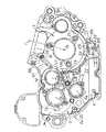
【図1】本願発明を適用したドライサンプ式4サイクルエンジンの右側クランクケース部材の内面図(左側面図)である。
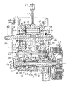
【図2】図1のII−II断面展開図である。
【図3】右側クランクケース部材の外面図(右側面図)である。
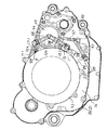
【図4】クラッチカバーを取り付けた状態を示す右側クランクケース部材内の外面図(右側面図)である。
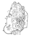
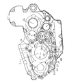
【図5】左側クランクケース部材の内面図(右側面図)である。
【図6】左側クランクケース部材の外面図(左側面図)である。
【図7】図4のVII−VII断面拡大図である。
【図8】図4のVIII−VIII断面拡大図である。
【図9】クランクケースの前部の平面図である。
【図10】図9のX−X断面拡大図である。
【図11】エンジン内のオイル全体の流れを示すブロック図である。
【図12】従来例の右側クランクケース部材の外面図である。
【符号の説明】
1 クランク軸
2 クランクケース
2a 左側クランクケース部材
2b 右側クランクケース部材
4 クランク室
5 ミッション室
8 ピストン
8a ピストン後端部
8b ピストン前端部
9 オイルタンク室
11 コンロッド
17 クランクウエブ
110 横断型オイル通路管(横断型オイル通路形成部材)
111 横断型オイル通路
112 噴出口[0001]
TECHNICAL FIELD OF THE INVENTION
TECHNICAL FIELD The present invention relates to an oil supply path of a four-cycle engine suitable for a vehicle such as a motorcycle or a riding-type four-wheeled vehicle for running on rough terrain.
[0002]
[Prior art]
The four-stroke engine is usually provided with an oil pump and an oil supply path from the oil pump to each lubrication point. The lubrication points include a crankshaft, a connecting rod, a piston, and a cylinder head. This corresponds to a valve operating cam mechanism, a transmission gear, a clutch, and the like (for example, see Patent Document 1).
[0003]
In order to efficiently supply oil from one oil pump to each of the above-described oiling points distributed in the engine, an oil extending from one side to the other side in the crankshaft core direction of the crankcase is provided in the oil supply path. A passage may be provided.
[0004]
As described above, the structure of the oil passage that connects one side and the other side in the crankshaft center direction of the crankcase has conventionally been an external piping structure in which pipes and tubes are piped outside the engine, or a wall of the crankcase. For example, a structure in which an oil passage is directly formed in the inside is adopted.
[0005]
As an example of a structure in which an oil passage is formed directly in a crankcase wall, for example, as shown in FIG. There is an engine in which an
[0006]
In addition, the applicant of the present application examined the patent document regarding the oil passage of the crankcase crossing type related to the present invention, but could not find any patent document that seems to be closely related.
[0007]
[Patent Document 1] Japanese Utility Model Publication No. 2-48657.
[0008]
[Problems to be solved by the invention]
In the former external piping structure, the number of piping parts such as tubes and joint pipes increases, so that the cost increases and the number of assembling steps also increases.
[0009]
In the structure formed in the crankcase wall corresponding to FIG. 12, the crankcase becomes large and the weight increases.
[0010]
[Object of the invention]
It is an object of the present invention to maintain the compactness of the crankcase by effectively utilizing the dead space in the crankcase and forming a transverse oil passage crossing the crankcase in the direction of the crankshaft center, and Another object of the present invention is to provide a four-stroke engine oil supply path which can ensure the ease of manufacture and assembly.
[0011]
It is another object of the present invention to allow the internal surface of the piston to be forcibly cooled without providing a dedicated pipe.
[0012]
[Means for Solving the Problems]
In order to solve the above-mentioned problem, an invention according to claim 1 of the present application is directed to a four-stroke engine oil supply path for pumping oil to each lubrication point in an engine, wherein a connecting rod trajectory and a crank web trajectory are viewed in a direction of a crankshaft center. And the bottom dead center of the piston is located within the range enclosed by the rear end of the skirt or the front end of the skirt. And a tubular oil passage forming member that crosses substantially parallel to the above.
[0013]
According to the above configuration, the crankcase crossing type oil passage forming member is arranged by effectively utilizing the dead space in the crankcase, so that the crankcase can be prevented from being enlarged. Further, the oil passage forming member functions as reinforcing ribs on the left and right side walls of the crankcase, and the rigidity is also improved.
[0014]
According to a second aspect of the present invention, in the oil supply path of the four-stroke engine according to the first aspect, an oil outlet opening toward the lower surface of the top wall of the piston is formed in the oil passage forming member. It is characterized.
[0015]
According to the above configuration, the inner surface of the piston can be cooled without forming a dedicated pipe or oil passage for cooling the inner surface of the piston, and the cooling effect of the piston can be improved at low cost.
[0016]
According to a third aspect of the present invention, in the oil supply path of the four-stroke engine according to the first or second aspect, the oil passage forming member is formed by being divided into left and right crankcase members of a left-right split crankcase. By combining the case members, the tip surfaces of the left and right oil passage forming members are butt-connected.
[0017]
According to the above configuration, manufacture and assembly of the crankcase crossing type oil passage forming member are simple.
[0018]
BEST MODE FOR CARRYING OUT THE INVENTION
1 to 10 show a dry-sump single-cylinder four-cycle engine to which the present invention is applied, which is mounted on, for example, a motorcycle for motocross. One embodiment of the present invention will be described with reference to these drawings. For convenience of description, the description will be made assuming that the crankshaft center direction is the left-right direction.
[0019]
[Crank chamber, transmission chamber and oil tank chamber]
FIG. 1 is a vertical sectional side view showing the inside of the right half of the
[0020]
A cylinder 6 is fastened to the upper surface of the
[0021]
Between the
[0022]
The
[0023]
A
[0024]
In the
[0025]
The oil is stored in the
[0026]
[Crankshaft]
FIG. 2 is an exploded cross-sectional view taken along the line II-II of FIG. 1. The
[0027]
Crankshaft support holes 41 and 42 are formed in left and
[0028]
The right end of the crankshaft 1 penetrates through the right
[0029]
The left end of the crankshaft 1 penetrates through the left main bearing 37 and projects into the
[0030]
An
[0031]
[Mission]
The
[0032]
An oil passage 71 communicating with the left
[0033]
[Pump structure]
In FIG. 2, the engine includes two oil pumps: a scavenging
[0034]
Each of the
[0035]
Pump covers 80 and 81 are fastened to end surfaces of the
[0036]
The
[0037]
The right feed pump shaft 83 projects into the right
[0038]
[Clutch room, etc.]
FIG. 3 shows the outer surface (right side surface) of the
[0039]
A
[0040]
3, a
[0041]
An
[0042]
FIG. 4 is a side view showing a state in which the
[0043]
[Structure related to oil supply and transverse oil passage]
At the lower end of the
[0044]
FIG. 7 is an enlarged cross-sectional view taken along the line VII-VII of FIG. 4. A
[0045]
The
[0046]
FIG. 8 is an enlarged cross-sectional view taken along the line VIII-VIII of FIG. 4. The
[0047]
FIG. 9 is a plan view of the
[0048]
The
[0049]
FIG. 10 is an enlarged cross-sectional view taken along the line XX of FIG. 9. An
[0050]
FIG. 5 is an inner surface (right side view) of the
[0051]
The
[0052]
[Structure related to oil return]
FIG. 6 shows the outer surface (left side surface) of the
[0053]
A
[0054]
That is, the oil flowing from the generator chamber through the
[0055]
The
[0056]
[Action]
[Drive of pump]
2, the rotation of the crankshaft 1 is transmitted to the feed pump shaft 83 via the pump driving
[0057]
Further, it is transmitted directly from the feed pump shaft 83 to the scavenging
[0058]
The two
[0059]
[Oil flow to each lubrication point]
(1) FIG. 11 is a block diagram briefly summarizing the oil circulation in the engine. The oil circulation during operation of the engine will be described with reference to FIG. The oil sucked into the
[0060]
(2) The oil filtered by the
[0061]
(3) The oil supplied to the
[0062]
(4) The oil that has reached the left side wall of the crankcase through the inside of the
[0063]
[Return of oil from each lubrication point]
(1) The oil used for lubrication of the
[0064]
(2) The oil that has overflowed from the
[0065]
(3) The oil used for lubrication around the crankshaft 1 and the oil used for cooling the inner surface of the
[0066]
(4) The oil used for lubrication around the cylinder head and the camshaft and the like falls or flows down into the
[0067]
(5) As described above, the return oil from around the cylinder head, the camshaft, the crankshaft 1, and the
[0068]
[Other embodiments of the invention]
(1) In the above-described embodiment, the
[0069]
(2) The position of the transverse oil passage forming member is, in the above embodiment, the rear end of the skirt 8a of the
[0070]
(3) The transverse oil passage forming member may be formed of a pipe member separate from the crankcase.
[0071]
【The invention's effect】
As described above, according to the present invention, (1) when viewed in the direction of the crankshaft center, the connecting rod trajectory, the crank web trajectory, and the bottom dead center are located within the range surrounded by the rear end portion or the front end portion of the skirt of the piston. In addition, since a tubular oil passage forming member that crosses the inside of the crankcase substantially in parallel with the direction of the crankshaft is disposed so as to pass through the bore range when viewed in the cylinder centerline direction, The dead space can be effectively used for arranging the oil passage, and an increase in the size of the crankcase can be prevented. Further, the oil passage forming member functions as reinforcing ribs on the left and right side walls of the crankcase, and the rigidity of the crankcase is improved.
[0072]
(2) If an oil outlet opening toward the lower surface of the top wall of the piston is formed in the middle of the oil passage forming member, a pipe dedicated to cooling the inner surface of the piston or an oil passage is not formed. The inner surface can be cooled, and the cooling effect of the piston can be improved at low cost.
[0073]
(3) The oil passage forming member is formed by dividing the left and right crankcase members into right and left crankcase members of a left-right split crankcase, and the left and right oil passage forming members are butt-connected to each other by joining the left and right crankcase members. , The manufacture and assembly of the transverse oil passage is simple.
[Brief description of the drawings]
FIG. 1 is an inner view (left side view) of a right crankcase member of a dry sump type four-stroke engine to which the present invention is applied.
FIG. 2 is an expanded sectional view taken along line II-II of FIG.
FIG. 3 is an external view (a right side view) of a right crankcase member.
FIG. 4 is an external view (right side view) of the inside of a right crankcase member showing a state where a clutch cover is attached.
FIG. 5 is an inner view (right side view) of a left crankcase member.
FIG. 6 is an external view (left side view) of a left crankcase member.
FIG. 7 is an enlarged sectional view taken along line VII-VII of FIG. 4;
8 is an enlarged cross-sectional view taken along line VIII-VIII of FIG.
FIG. 9 is a plan view of a front portion of the crankcase.
FIG. 10 is an enlarged cross-sectional view taken along line XX of FIG. 9;
FIG. 11 is a block diagram showing the flow of the entire oil in the engine.
FIG. 12 is an external view of a conventional right crankcase member.
[Explanation of symbols]
DESCRIPTION OF SYMBOLS 1
111
Claims (3)
クランク軸芯方向に見て、コンロッド軌跡とクランクウエブ軌跡と下死点のピストンのスカート後端部又はスカート前端部で囲まれた範囲内に位置すると共に、シリンダ中心線方向に見てボア範囲内を通過するように、クランクケース内をクランク軸芯方向と略平行に横断する筒状のオイル通路形成部材を配置していることを特徴とする4サイクルエンジンのオイル供給経路。In the oil supply path of a four-stroke engine that pumps oil to each lubrication point in the engine,
When viewed in the direction of the crankshaft center, the connecting rod trajectory, the crank web trajectory, and the bottom dead center are located within the range surrounded by the rear end of the skirt or the front end of the skirt, and within the bore range viewed in the direction of the cylinder center line. Characterized by disposing a tubular oil passage forming member that crosses the inside of the crankcase substantially in parallel with the axis of the crankshaft so as to pass through the oil passage of the four-stroke engine.
Priority Applications (1)
| Application Number | Priority Date | Filing Date | Title |
|---|---|---|---|
| JP2002288917A JP4065751B2 (en) | 2002-10-01 | 2002-10-01 | 4-cycle engine oil supply path |
Applications Claiming Priority (1)
| Application Number | Priority Date | Filing Date | Title |
|---|---|---|---|
| JP2002288917A JP4065751B2 (en) | 2002-10-01 | 2002-10-01 | 4-cycle engine oil supply path |
Publications (2)
| Publication Number | Publication Date |
|---|---|
| JP2004124792A true JP2004124792A (en) | 2004-04-22 |
| JP4065751B2 JP4065751B2 (en) | 2008-03-26 |
Family
ID=32281281
Family Applications (1)
| Application Number | Title | Priority Date | Filing Date |
|---|---|---|---|
| JP2002288917A Expired - Fee Related JP4065751B2 (en) | 2002-10-01 | 2002-10-01 | 4-cycle engine oil supply path |
Country Status (1)
| Country | Link |
|---|---|
| JP (1) | JP4065751B2 (en) |
Cited By (6)
| Publication number | Priority date | Publication date | Assignee | Title |
|---|---|---|---|---|
| JP2005030326A (en) * | 2003-07-08 | 2005-02-03 | Kawasaki Heavy Ind Ltd | Motorcycle engine and motorcycle equipped with the engine |
| JP2009085108A (en) * | 2007-09-29 | 2009-04-23 | Honda Motor Co Ltd | Oil filter layout structure in a motorcycle power unit |
| JP2010151086A (en) * | 2008-12-26 | 2010-07-08 | Kawasaki Heavy Ind Ltd | Vehicle mounted with engine and the engine |
| CN102465996A (en) * | 2010-11-10 | 2012-05-23 | 日立汽车系统株式会社 | Crankcase integrated balancing device |
| JP2016223358A (en) * | 2015-05-29 | 2016-12-28 | 川崎重工業株式会社 | Mounting structure of piping member |
| JP2019052602A (en) * | 2017-09-15 | 2019-04-04 | スズキ株式会社 | Internal combustion engine |
-
2002
- 2002-10-01 JP JP2002288917A patent/JP4065751B2/en not_active Expired - Fee Related
Cited By (8)
| Publication number | Priority date | Publication date | Assignee | Title |
|---|---|---|---|---|
| JP2005030326A (en) * | 2003-07-08 | 2005-02-03 | Kawasaki Heavy Ind Ltd | Motorcycle engine and motorcycle equipped with the engine |
| JP2009085108A (en) * | 2007-09-29 | 2009-04-23 | Honda Motor Co Ltd | Oil filter layout structure in a motorcycle power unit |
| JP2010151086A (en) * | 2008-12-26 | 2010-07-08 | Kawasaki Heavy Ind Ltd | Vehicle mounted with engine and the engine |
| CN102465996A (en) * | 2010-11-10 | 2012-05-23 | 日立汽车系统株式会社 | Crankcase integrated balancing device |
| JP2012102661A (en) * | 2010-11-10 | 2012-05-31 | Hitachi Automotive Systems Ltd | Crankcase integrated balancer device |
| US8662046B2 (en) | 2010-11-10 | 2014-03-04 | Hitachi Automotive Systems, Ltd. | Balancer integrated with crankcase |
| JP2016223358A (en) * | 2015-05-29 | 2016-12-28 | 川崎重工業株式会社 | Mounting structure of piping member |
| JP2019052602A (en) * | 2017-09-15 | 2019-04-04 | スズキ株式会社 | Internal combustion engine |
Also Published As
| Publication number | Publication date |
|---|---|
| JP4065751B2 (en) | 2008-03-26 |
Similar Documents
| Publication | Publication Date | Title |
|---|---|---|
| US6332444B1 (en) | Lubricating device for internal combustion engine | |
| US7559307B2 (en) | Oil filter mounting structure in internal combustion engine | |
| JP5667366B2 (en) | Crankcase structure of internal combustion engine | |
| US6823829B1 (en) | Dry-sump lubrication type four-stroke cycle engine | |
| US6305342B1 (en) | Lubrication system for internal combustion engine | |
| US6554104B2 (en) | Lubrication structure for internal combustion engine | |
| JP4704162B2 (en) | Engine breather structure | |
| US6318333B1 (en) | Accessory arrangement structure for internal combustion engine | |
| JP5352257B2 (en) | Internal combustion engine | |
| JP3052002B2 (en) | Oil tank structure of dry sump lubricated internal combustion engine | |
| JP4065751B2 (en) | 4-cycle engine oil supply path | |
| JP3668460B2 (en) | Dry sump 4-cycle engine | |
| US8893682B2 (en) | Multi-cylinder internal combustion engine | |
| US8381697B2 (en) | Internal combustion engine | |
| JP5078806B2 (en) | Engine lubrication structure | |
| JP4031683B2 (en) | Dry sump 4-cycle engine | |
| JP2004108236A (en) | Oil pump for 4-cycle engine | |
| JP4372481B2 (en) | Motorcycle engine and motorcycle equipped with the engine | |
| JP3470355B2 (en) | Dry sump engine oil passage | |
| JP4275479B2 (en) | Motorcycle engine and motorcycle equipped with the engine | |
| JP2007146816A (en) | Lubricating device for internal combustion engine | |
| JP2003293722A (en) | Dry sump type 4-cycle engine | |
| JP4495418B2 (en) | Motorcycle engine and motorcycle equipped with the engine | |
| JP2003239714A (en) | Dry sump type 4-cycle engine | |
| JP2684639B2 (en) | Engine lubrication structure |
Legal Events
| Date | Code | Title | Description |
|---|---|---|---|
| A621 | Written request for application examination |
Free format text: JAPANESE INTERMEDIATE CODE: A621 Effective date: 20050411 |
|
| A977 | Report on retrieval |
Free format text: JAPANESE INTERMEDIATE CODE: A971007 Effective date: 20070919 |
|
| A131 | Notification of reasons for refusal |
Free format text: JAPANESE INTERMEDIATE CODE: A131 Effective date: 20071002 |
|
| A521 | Written amendment |
Free format text: JAPANESE INTERMEDIATE CODE: A523 Effective date: 20071130 |
|
| TRDD | Decision of grant or rejection written | ||
| A01 | Written decision to grant a patent or to grant a registration (utility model) |
Free format text: JAPANESE INTERMEDIATE CODE: A01 Effective date: 20071225 |
|
| A61 | First payment of annual fees (during grant procedure) |
Free format text: JAPANESE INTERMEDIATE CODE: A61 Effective date: 20080107 |
|
| R150 | Certificate of patent or registration of utility model |
Free format text: JAPANESE INTERMEDIATE CODE: R150 |
|
| FPAY | Renewal fee payment (event date is renewal date of database) |
Free format text: PAYMENT UNTIL: 20110111 Year of fee payment: 3 |
|
| LAPS | Cancellation because of no payment of annual fees |