JP2004128455A - Magnetic material, method for manufacturing the same, magnetic sensor using magnetic material, and magnetic circuit component incorporated in the magnetic sensor - Google Patents
Magnetic material, method for manufacturing the same, magnetic sensor using magnetic material, and magnetic circuit component incorporated in the magnetic sensor Download PDFInfo
- Publication number
- JP2004128455A JP2004128455A JP2003153387A JP2003153387A JP2004128455A JP 2004128455 A JP2004128455 A JP 2004128455A JP 2003153387 A JP2003153387 A JP 2003153387A JP 2003153387 A JP2003153387 A JP 2003153387A JP 2004128455 A JP2004128455 A JP 2004128455A
- Authority
- JP
- Japan
- Prior art keywords
- magnetic
- resin
- powder
- metal powder
- flat
- Prior art date
- Legal status (The legal status is an assumption and is not a legal conclusion. Google has not performed a legal analysis and makes no representation as to the accuracy of the status listed.)
- Pending
Links
Images




Landscapes
- Measuring Magnetic Variables (AREA)
- Soft Magnetic Materials (AREA)
Abstract
【課題】形状の自由度及び比透磁率を高くすることができる磁性材及びその製造方法を提供する。
【解決手段】樹脂33,34中に磁性金属粉体31A,31B,31C,32を設ける磁性材であって、磁性金属粉体31A,31B,31C,32は偏平形状に形成されている。そして隣接するそれぞれの磁性金属粉体31A,31A´、31B,31B´、31C,31C´、32,32´の長手方向X,X´を相互にほぼ平行に配向する。磁性金属粉体31A,31B,31C,32の長手方向X,X´を磁界の磁力線Yとほぼ平行に配向する。磁性金属粉体31A,31B,31C,32を用いた磁性材であっても、透磁率を向上することができる。また、磁性金属粉体31A,31B,31C,32は樹脂33,34中に配置されるので、磁性材の形状の自由度も向上できる。
【選択図】 図3An object of the present invention is to provide a magnetic material capable of increasing the degree of freedom in shape and relative magnetic permeability, and a method for manufacturing the same.
A magnetic material provided with magnetic metal powders (31A, 31B, 31C, 32) in resins (33, 34), wherein the magnetic metal powders (31A, 31B, 31C, 32) are formed in a flat shape. The longitudinal directions X, X 'of the adjacent magnetic metal powders 31A, 31A', 31B, 31B ', 31C, 31C', 32, 32 'are oriented substantially parallel to each other. The longitudinal directions X, X ′ of the magnetic metal powders 31A, 31B, 31C, 32 are oriented substantially parallel to the magnetic field lines Y of the magnetic field. Even with a magnetic material using the magnetic metal powders 31A, 31B, 31C, 32, the magnetic permeability can be improved. Further, since the magnetic metal powders 31A, 31B, 31C and 32 are disposed in the resins 33 and 34, the degree of freedom of the shape of the magnetic material can be improved.
[Selection diagram] FIG.
Description
【0001】
【発明の属する技術分野】
本発明は、磁場の中に置くと磁化する磁性材及びその製造方法並びに、例えば操舵トルクに応じた操舵補助力を付与する自動車用電動パワーステアリングにおける磁気センサーに及びその磁気センサーに組み込まれる磁気回路部品に関する。
【0002】
【従来の技術】
例えば磁性材として、鉄にけい素を混入したけい素鋼が周知である。そして、このようなけい素鋼帯を環状に巻き積層して巻鉄心を形成している。また、主としてラジオやテレビ等の通信回路で用いる磁心材料として圧粉心が周知である。この圧粉心は、磁性金属を粉状に形成し、その表面を絶縁層で覆い、結合材を用いて圧縮し固形状にしたものである。
【0003】
また、従来の自動車の電動パワーステアリングにおける磁気センサーは、図11及び図12に示すようにハンドルに繋がる入力軸 101と車輪に繋がる出力軸 103とをトーションバー 102を介して連結すると共に、前記入力軸 101と出力軸 103のそれぞれの端部に検出リング 104及びがトーションバー 102を内包するように嵌挿固定されており、検出リング 104の端部には多数の突起 107がリングの周方向に沿って設けられている。そして、検出リング 105の突起 107と検出リング 105の突起 108は相対して接近して設けられている。
【0004】
一方、断面コ字形のヨーク 109内にはコイル 106が保持されており、このコイル 106により磁束を発生することで図12に示されるように磁力線 110が形成され、それによって磁力線 110がヨーク 109、検出リング 104、検出リング 105、再びヨーク 109の回路を通って磁気回路が形成される。
【0005】
このような状態で入力側 101軸にトルクを与えるとトーションバー 102が捻れ、トルクに比例した角度だけ入力軸 101が出力軸 102に対して回転し、入力軸 101に固定された検出リング 105が、出力軸 103に固定された検出リング 105に対して相対的に回転し、検出リング 105の回転により突起 107が検出リング 105の突起 108に対して相対的にずれるようになっている。
【0006】
そして、入力軸 101の回転に伴う検出リング 104の回転により検出リング 104の突起 107と検出リング 105の突起 108の対向面積が変化し、それに伴って検出リング 104、検出リング 105及びヨーク 109を通る磁気回路における磁束密度が変化し、そのときコイル 106のコンダクタンスが変化してトルクの検出ができるようになっている。
【0007】
従来、磁力線がヨーク 109、検出リング 104、検出リング 105等を通る回路部品(以下、磁気回路構成部品という)は、一般にSUS410Lまたはその相当材等の金属材料で作られていた。しかし、金属材料は一般に周波数が低いと比透磁率は高く、金属材料からなる磁気回路構成部品を組み込んだ磁気センサーは高い検出精度を示すが、一層検出精度を上げるために周波数を上げると比透磁率が低下する欠点があった。
【0008】
そこで、合成樹脂に軟磁性粉末:80〜95質量%を含む磁性樹脂材料は周波数を高くしても金属材料のように比透磁率が極端に低くならない特性を有するところから、かかる磁性樹脂材料で磁気センサーの磁気回路構成部品を作製する提案がなされており、特に合成樹脂中に粒径が2μm以上の大粒径軟磁性粉末と粒径が0.05μm以下の小粒径常磁性粉末からなる磁性粉末を80〜95%質量%含む磁性樹脂材料からなる磁気回路構成部品は優れた効果があるとされている(特許文献1参照)。
【0009】
【特許文献1】
特開2000−292275号公報
【0010】
【発明が解決しようとする課題】
前述のような鋼帯を積層した磁性材は比透磁率を向上することができる反面、形状の自由度に劣るという問題があった。また、前述の圧粉心においては、形状の自由度は向上するものの、比透磁率には限界があった。
【0011】
前述の磁気センサーにおける軟磁性粉末は、周波数を上げても比透磁率の変化が極めて少ないという優れた特性を有しているが、前記従来の磁気樹脂材料は比透磁率自体が低いために従来の磁性樹脂材料からなる磁気回路構成部品を組み込んだ磁気センサーの検出精度は依然として満足の行くものではなかった。
【0012】
そこで、本発明は、形状の自由度及び比透磁率を高くすることができる磁性材及びその製造方法を提供することを目的とする。また、本発明は、周波数を上げても比透磁率が低下することがなく、さらに比透磁率の高い特性を有する磁気回路構成部品を開発して、その磁気回路構成部品を組み込んだ一層検出特性の優れた磁性材を用いた磁気センサー及びその磁気センサーに組み込まれる磁気回路部品を提供することを目的とする。
【0013】
【課題を解決するための手段】
請求項1の発明は、樹脂中に磁性金属粉体を設けて磁界に配置される磁性材であって、前記磁性金属粉体は偏平形状に形成され、隣接するそれぞれの前記磁性金属粉体の長手方向を相互にほぼ平行に配向するとともに、前記磁性金属粉体の長手方向を前記磁界の磁力線とほぼ平行に配向したことを特徴とする磁性材である。
【0014】
この請求項1の構成によれば、前記磁性金属粉体は偏平形状に形成され、その長手方向を相互にほぼ平行に配向して、透磁率を向上することができ、また、磁性金属粉体は樹脂中に配置されて成形される。さらに前記磁性金属粉体の長手方向を前記磁界の磁力線とほぼ平行に配向されている。
【0015】
請求項2の発明は、樹脂中に磁性金属粉体を設けて屈曲方向に磁界が配置される磁性材の角部において、前記磁性金属粉体は偏平形状に形成され、前記磁性金属粉体の長手方向を屈曲した前記磁界の磁力線とほぼ平行に配向したことを特徴とする磁性材である。
【0016】
この請求項2の構成によれば、前記磁性金属粉体は偏平形状に形成され、その長手方向を相互にほぼ平行に配向して、角部において透磁率を向上することができる。
【0017】
請求項3の発明は、樹脂中に磁性金属粉体を設ける磁性材であって、前記磁性金属粉体は偏平形状に形成され、隣接するそれぞれの前記磁性金属粉体の長手方向を相互にほぼ平行になるように配向する磁性材の製造方法において、前記磁性金属粉体を樹脂と共に金型のキャビティに射出して成形を行うことを特徴とする磁性材の製造方法である。
【0018】
この請求項3の構成によれば、磁性金属粉体を樹脂と共に金型のキャビティに射出することで、溶融樹脂の流れにより偏平形状の磁性金属粉体は抵抗を受けてその長手方向が規制されて磁性金属粉体を一様な方向に向けて樹脂内に配置できる。
【0019】
請求項4の発明は、前記射出時における前記キャビティ内の前記磁性金属粉体と樹脂を一方向の流れとすることを特徴とする請求項3記載の磁性材の製造方法である。
【0020】
この請求項4の構成によれば、前記キャビティ内の前記磁性金属粉体と樹脂を、旋回等戻って樹脂相互が突き当たることのない一方向の流れとすることで、溶融樹脂の一方向の流れにより偏平形状の磁性金属粉体は抵抗を受ける。
【0021】
請求項5の発明は、樹脂中に磁性金属粉体を設けて磁界に配置される磁性材であって、前記磁性金属粉体は偏平形状に形成され、隣接するそれぞれの前記磁性金属粉体の長手方向を相互にほぼ平行になるように配向する磁性材の製造方法において、前記磁性金属粉体と樹脂を金型のキャビティに射出して成形を行い、前記射出時における前記キャビティ内の前記磁性金属粉体と樹脂を一方向の流れとし、かつ前記一方向の流れを前記磁界の磁力線とほぼ平行になるようにしたことを特徴とする磁性材の製造方法である。
【0022】
この請求項5の構成によれば、前記キャビティ内の前記磁性金属粉体と樹脂を、旋回等戻って樹脂相互が突き当たることのない一方向の流れとすることで、溶融樹脂の一方向の流れにより偏平形状の磁性金属粉体は抵抗を受ける。さらに前記磁性金属粉体の一方向の流れを前記磁界の磁力線とほぼ平行に配向される。
【0023】
請求項6の発明は、前記金型に磁場を配設して射出することを特徴とする請求項3〜5のいずれか1項に記載の磁性材の製造方法である。
【0024】
この請求項6の構成によれば、磁性金属粉体は金型に配設された磁場によって配向されて射出成形を行うことができる。
【0025】
請求項7の発明は、前記金型内にコイルを配置し、前記磁性金属粉体と樹脂を金型のキャビティに射出して一体成形することを特徴とする請求項3〜5のいずれか1項に記載の磁性材の製造方法である。
【0026】
この請求項7の構成によれば、磁性金属粉体をコイルと一体的に成形することができる。
【0027】
請求項8の発明は、樹脂中に磁性金属粉体を設ける磁性材であって、前記磁性金属粉体は偏平形状に形成され、隣接するそれぞれの前記磁性金属粉体の長手方向を相互にほぼ平行になるように配向する磁性材の製造方法において、前記磁性金属粉体と樹脂を型開状態の金型に収容した後、型閉して金型成形を行うときに前記金型に磁場を配設して成形を行うことを特徴とする磁性材の製造方法である。
【0028】
この請求項8の構成によれば、磁性金属粉体は金型に配設された磁場によって配向されて射出成形を行うことができる。
【0029】
また、(a)合成樹脂中に軟磁性粉末が分散して含まれる磁性樹脂材料からなる磁気回路構成部品が組み込まれており、磁気回路構成部品を通る磁力線の変化を検出する磁気センサーにおいて、前記磁性樹脂材料に含まれる軟磁性粉末を偏平形状軟磁性粉末とし、この偏平形状軟磁性粉末の長軸方向が磁力線方向に平行に配合して合成樹脂中に分散している磁性樹脂材料(以下、偏平粉末含有磁性材料という)からなる磁気回路構成部品は、検出精度を上げるために周波数を高くしても比透磁率が低下することが極めて少なく、この磁気回路構成部品を組み込んだ磁気センサーは、一層優れた検出精度を示す。
(b)前記偏平粉末含有磁気樹脂材料に含まれる扁平形状軟磁性粉末は、短軸長をa、長軸長をbとするとアスペクト比(a/b)が0.4以下でありかつ長軸長bが10μm以上、2mm以下である偏平形状軟磁性粉末であることが好ましく、この偏平形状軟磁性粉末は合成樹脂中に30〜95体積%分散して含まれていることが好ましい、という研究結果に基づき、
請求項9の発明は、合成樹脂中に偏平形状軟磁性粉末が分散して含まれる磁性樹脂材料で構成された磁気回路を構成する磁気回路構成部品が組込まれ、前記磁気回路構成部品を通る磁力線の変化に基づいて変位を検出する磁気センサーであって、前記磁気回路構成部品は合成樹脂中に偏平形状軟磁性粉末を含む偏平粉末含有磁性樹脂材料からなり、かつ前記偏平粉末含有磁性樹脂材料に含まれる偏平形状軟磁性粉末は長軸方向が前記部品を通る磁力線にほぼ平行に配向していることを特徴とする磁気センサーである。
【0030】
請求項10の発明は、合成樹脂中に偏平形状軟磁性粉末が分散して含まれる磁性樹脂材料で構成された磁気回路を構成する磁気回路構成部品が組込まれ、前記磁気回路構成部品を通る磁力線の変化に基づいて変位を検出する磁気センサーであって、前記磁気回路構成部品は合成樹脂中に偏平形状軟磁性粉末:30〜95体積%を含む偏平粉末含有磁性樹脂材料からなり、かつ前記偏平粉末含有磁性樹脂材料に含まれる偏平形状軟磁性粉末は長軸方向が前記部品を通る磁力線にほぼ平行に配向していることを特徴とする磁気センサーである。
【0031】
請求項11の発明は、前記樹脂材料に含まれる前記偏平形状軟磁性粉末は、短軸長をa、長軸長をbとするとアスペクト比(a/b)が0.4以下であり、かつ長軸長bが10μm以上、2mm以下であることを特徴とする請求項9記載の磁気センサーである。
【0032】
そして、この磁気センサーに組み込まれる磁気回路構成部品は、具体的には、検出リング、断面コの字状のヨークである。これら磁気回路構成部品における少なくとも磁力線が通る部分はこの磁力線にほぼ平行に偏平形状軟磁性粉末の長軸方向が揃うように配向する必要がある。したがって、請求項12の発明においては、前記磁気回路構成部品は、検出子であることを特徴とする請求項9〜11のいずれか1項に記載の磁気センサーであり、また請求項13の発明においては、前記磁気回路構成部品は、ヨークであることを特徴とする請求項9〜11のいずれか1項に記載の磁気センサーである。
【0033】
【発明の実施形態】
以下、本発明の一実施形態を図1〜図6を参照して説明する。実施形態は自動車の電動式パワーステアリング装置の磁気センサーとしての非接触式変位センサーに用いられる検出コイルのコイル収納部材の例を示している。非接触式変位センサーは、図1に示すようにステアリングホイール(図示せず)に連結された入力軸1と、操舵輪側に連結された出力軸2と、これらの軸1,2を連結するトーションバー3と、このトーションバー3の外周側の、入力軸1側及び出力軸2側にそれぞれ対向配置させた第1及び第2検出リング4,5と、入力軸1にトルクを作用させたときのトーションバー3の変位量に応じて変位する第1検出リング4の第2検出リング5に対する相対変位量をインダクタンスの変化として非接触で検出する第1検出コイル6を有する第1磁心7とを有する。そして、前記第1検出リング4の第2検出リング5に対向する端面の外周側に、該外周に沿って突部4Aが間隔をおいて設けられる。同様に、前記第2検出リング5の第1検出リング4に対向する端面の外周側に、該外周に沿って突部5Aが間隔をおいて設けられる。
【0034】
前記第1磁心7は、コイルボビンに巻き付けられた第1検出コイル6と、該検出コイル6を検出リング4,5の外周面から一定間隔で離隔させた位置に保持する外周部8とその両側に配置される一側及び他側の側面部8A,8Bを備えた円環状の第1コイル収納部材9と、前記第1検出コイル6に一端が連結され、他端を第1コイル収納部材9の外側に導出したリード線10とによって構成されている。
【0035】
そして、前記第1,2検出リング4,5及び後述する第3検出リング21は、透磁性の金属粉末を所定形状に圧縮成形することによって得られる圧粉体を焼結した焼結体により形成される。これは図2に示すようにステンレス鋼等鉄系粉末11をダイ12に形成された型13に収容した後に、パンチ14によって粉末11をプレスして所定形状の圧粉体を形成し、さらにこの圧粉体を雰囲気ガス中で焼結したものであり、該圧粉体の焼結体においては内部には粉末11間に多数の空孔が形成されている。
【0036】
さらに、前記トーションバー3の入力軸1側に第3検出リング21を設ける。すなわち、第1検出リング4の突部4Aと反対側の端面に対向して第3検出リング21を設ける。そしてそれぞれ対向配置させた第1及び第3検出リング4,21と、入力軸1にトルクを作用させたときのトーションバー3の変位量に応じて変位する第1検出リング4の第3検出リング21に対する相対変位量をインダクタンスの変化として非接触で検出する第2検出コイル22を有する第2磁心23とを有する。そして、前記第3検出リング21の第1検出リング4に対向する端面の外周側に、該外周に沿って突部21Aが間隔をおいて設けられる。前記第2磁心23は、コイルボビンに巻き付けられた第2検出コイル22と、該検出コイル22を検出リング4,21の外周面から一定間隔で離隔させた位置に保持する円環状の第2コイル収納部材24と、前記第2検出コイル22に一端が連結され、他端を第2コイル収納部材24の外側に導出したリード線25とによって構成されている。尚、第1、第3検出リング4,21、第2検出コイル22及び第2コイル収納部材24によって、補償用の非接触式変位センサーを構成する。尚、図7に示すように第1コイル収納部材9及び第2コイル収納部材24は、外周部8と一側の側面部8Aと他側の側面部8B一体に連結したようなものでもよい。
【0037】
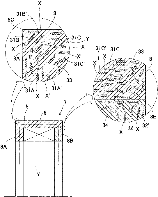
図1に示すように、前記検出コイル6を検出リング4,5の外周面から一定間隔で離隔させた位置に保持する外周部8とその両側に配置される一側及び他側の側面部8A,8Bを備えた円環状の第1コイル収納部材9は、フェライト系ステンレス鋼やけいそ鋼等の粉状或いは粒状の(強)磁性金属粉体31A,31B,31C,32を、6−6ナイロン等熱可塑性樹脂33,34の中に設けた磁性材である。そして、前記磁性金属粉体31A,31B,31C,32は圧力をかけて偏平形状に形成されている。尚、偏平形状の磁性金属粉体31A等の厚み(短軸長a)に対する長手方向の長さ(長軸長b)、すなわち縦横比(アスペクト比a/b)は、0.5より小さく形成される(a/b<0.5)。磁気センサーの場合では好ましくは0.4以下である。また、長軸長bは、5μm以上、5mm以下、磁気センサーの場合では好ましくは長軸長bは、10μm以上、2mm以下である。さらに隣接するそれぞれの前記磁性金属粉体31A,31A´、31B,31B´、31C,31C´、32,32´の長手方向X,X´を相互にほぼ平行になるように配向するようにしている。さらに詳述すると、内側を開口するように断面をコ形に形成した円環状の第1コイル収納部材9は、外周部8と一側の側面部8Aとを一体化した部位と、他側の側面部8Bの部位とを一体に連結するとともに、開口に検出コイル6を収容したものである。そして、側面部8Aにおいて隣接する磁性金属粉体31A,31A´相互は、その長手方向X,X´を相互にほぼ平行に配向するとともに、長手方向X,X´は後述する磁力線Yの方向とほぼ一致するように側面部8Aの長手方向とほぼ平行に配向している。尚、前記ほぼ平行とは一方の長手方向Xに対して他方の長手方向X´との交差角度が45°、好ましくは30°以下になっていることを示す。また、長手方向X,X´は磁界方向Yとほぼ一致するとは、磁界方向Yに対して長手方向X,X´の交差角度が45°、好ましくは30°以下になっていることを示す。さらに、外周部8において隣接する磁性金属粉体31C,31C´相互は、その長手方向X,X´を、ほぼ平行に配向され、さらに長手方向X,X´は磁界方向Yとほぼ一致するように外周部8の長手方向とほぼ平行に配向されている。また、外周部8と側面部8Aとの角部8Cにおいては、隣接する磁性金属粉体31B,31B´相互は、その長手方向X,X´を、ほぼ平行に配向され、さらに長手方向X,X´は磁界方向Yとほぼ一致するように角部8Cの傾斜方向とほぼ平行に配向されている。尚、傾斜方向とは、磁界Yの接線方向とほぼ同じになることをいう。一方、側面部8Bにおいて隣接する磁性金属粉体32,32´相互は、その長手方向X,X´を相互にほぼ平行に配向するとともに、長手方向X,X´は磁界方向Yとほぼ一致するように側面部8Bの長手方向とほぼ平行に配向されている。
【0038】
そして、前記構成により、ハンドルを回動することにより入力軸1が回動し、トーションバー3が回動する。これにより、第1及び第2検出リング4,5間に形成されていた磁界(磁力線Y)、第1及び第3検出リング4,21間に形成されていた磁界(磁力線)が、第1及び第2検出リング4,5間、第1及び第3検出リング4,21間の相対角度がそれぞれ変化する。この角度の変化に応じて相対変位量を第1及び第2検出コイル6,22を介して磁界のインダクタンスの変化としてそれぞれ検出するものである。
【0039】
そして、第1及び第2検出リング4,5間に形成されていた磁界の磁力線Yと、偏平形状に形成された隣接した磁性金属粉体31A,31A´、31B,31B´、31C,31C´、32,32´の長手方向X,X´を相互にほぼ平行に配向することにより、外周部8と一側の側面部8Aとを一体化した部位と、他側の側面部8Bの部位のそれぞれの透磁率を向上することができる。そして、磁性金属粉体31A,31A´、31B,31B´、31C,31C´、32,32´の長手方向X,X´は、第1及び第2検出リング4,5間の磁力線Yともほぼ平行に配向されているので、磁気特性の向上を図ることができる。
【0040】
次に前記外周部8と一側の側面部8Aとを一体化した部位について、その製造方法について説明する。製造方法は、金属粉体を樹脂中に混練して射出成形を行うメタルインジェクションモールド(MIM)により行なうものである。次に図4(A)を参照して詳述する。41は固定側金型42を取り付けた固定ダイプレート、43は金型取付板44を介して可動側金型45を取り付けた可動ダイプレートであり、該可動ダイプレート43は、図示していないが適宜の型締駆動源によって前後に駆動され、可動側金型45を固定側金型42に密着させた型締位置と、可動側金型45を固定側金型42から離間させた型開位置とをとり得るようになっている。そして、可動側金型45が固定側金型42に密着した状態では、両金型42,45によって成形品(製品)形成用空間たるキャビティ46が形成され、該キャビティ46は通常図示せぬ適宜ゲート、ランナーおよびスプルー47を介して樹脂注入口48と連通している。49は公知の加熱シリンダで、該加熱シリンダ49先端のノズルが前記樹脂注入口48に押し付けられている。50は、加熱シリンダ49内に回転並びに前後動可能であるように配設されたスクリューで、図示せぬ適宜の回転駆動源によって回転駆動可能とされていると共に、本実施例では、図示しない射出用サーボモータによってボールネジ機構等の回転−直線運動変換メカニズムを介して前後進駆動可能とされている。このスクリュー50は、混練・可塑化・計量行程(チャージ行程)時には図示せぬ回転駆動源によって所定方向に回転駆動され、これによって、図示せぬホッパーからスクリュー50の後端側に投入された磁性金属粉体31と熱可塑性樹脂原料(樹脂ペレット)を、混練・可塑化しながらスクリュー50の前方側に送り込み、スクリュー50の前方側に溶融樹脂が溜るにしたがって背圧を制御されながら後退し、スクリュー50の前方側に1ショット分の溶融樹脂が貯えられた時点(計量完了時点)でスクリュー回転が停止される。そして、この後所定秒時を経た射出開始タイミングに至ると、前記射出用サーボモータによってスクリュー50が前進駆動され、これによって1ショット分の溶融樹脂が前記した金型のキャビティ46内に射出・充填されるようになっている。
【0041】
このように、前記製造時においては、金型のキャビティ46内に混練した磁性金属粉体31と熱可塑性原料樹脂33が、キャビティ46内に射出・充填される際、樹脂原料33はスプルー47より二股状に分かれるが、旋回等戻って樹脂相互が突き当たることのない一方向の流れとなっている。これはキャビティ46の形状が、溶融した樹脂33の衝突突き合せ箇所がないことに起因している。さらに射出時において、磁性金属粉体31は、溶融した熱可塑性樹脂原料33の抵抗を受けて、図3に示すように磁性金属粉体31A,31A´、31B,31B´、31C,31C´、32,32´の長手方向X,X´は樹脂流れ方向Zと同じような方向となって、この結果隣接するそれぞれの磁性金属粉体31A,31A´、31B,31B´、31C,31C´の長手方向X,X´を相互にほぼ平行に配向することができる。尚、金型においては予めキャビティ46の形状、樹脂注入口48の位置、方向などを、磁性金属粉体31は、溶融した熱可塑性樹脂原料33の抵抗を受けて、磁性金属粉体31A,31A´、31B,31B´、31C,31C´の長手方向X,X´を相互にほぼ平行に配向することができるようにする。またその長手方向X,X´が磁力線Yとほぼ平行になるように配向する。
【0042】
図5は、磁性材の400倍の拡大写真であり、黒色に示された熱可塑性樹脂33中に、白色に示された磁性金属粉体31が相互に平行に配置されていることが判明している。また、図6は透磁率と周波数との関連を示す交流磁気特性グラフであり、白点は磁性金属粉体が偏平な本願発明に係るものであり、黒点は磁性金属粉体が粒状な比較例に係るものである。本願発明に係るものは、比較例に係るものに比較して約3倍の透磁率を発揮できることが判明する。
【0043】
尚、前述の外周部8と一側の側面部8Aとを一体化した部位を成形する際に、図4(B)に示すように成形品(製品)形成用空間たるキャビティ46A内に、前述のコイル6を予め収容した状態で磁性金属粉体31A…を設けた可塑性樹脂33を射出して、インサート成形を行ってもよい。
【0044】
さらに、前記側面部8Bも同様に型成形により製造される。この成形は図4(C)に示すように、一方の金型としての固定側金型42Bと、他方の金型としてのキャビティ46Bを形成した可動側金型45Bとを備えており、型開状態でキャビティ46Bに磁性金属粉体を設けた可塑性樹脂33を収容し、そして型閉した後に冷却して成形を行うものである。このような成形においては、偏平な磁性金属粉体31(図示せず)の長手方向は、可動側金型45Bの押圧力により押圧方向Pと直交する方向となる。尚、このような型成形にあっても図4(B)に示すようにコイルを予め収容したインサート成形を行ってもよい。
【0045】
以上のように、前記実施形態では、樹脂33,34中に磁性金属粉体31A,31B,31C,32を設ける磁性材であって、前記磁性金属粉体31A,31B,31C,32は偏平形状に形成され、隣接するそれぞれの前記磁性金属粉体31A,31A´、31B,31B´、31C,31C´、32,32´の長手方向X,X´を相互にほぼ平行に配向することで、磁性金属粉体31A,31B,31C,32を用いた磁性材であっても、透磁率を向上することができる。また、磁性金属粉体31A,31B,31C,32は樹脂33,34中に配置されるので、磁性材の形状の自由度も向上できる。
【0046】
また、前記磁性金属粉体31A,31B,31C,32の長手方向X,X´を前記磁界の磁力線Yとほぼ平行に配向することで、各種磁気回路等に有効に利用することができ、また角部8Cにおいて、隣接する磁性金属粉体31B,31B´相互は、その長手方向X,X´を、ほぼ平行に配向され、さらに長手方向X,X´は磁界方向Yとほぼ一致するように角部8Cの傾斜方向とほぼ平行に配向されていることで、磁界の連続性が保たれ各種磁気回路等に有効に利用することができる。
【0047】
さらに、樹脂33中に磁性金属粉体31A,31B,31Cを設ける磁性材であって、前記磁性金属粉体31A,31B,31Cは偏平形状に形成され、隣接するそれぞれの前記磁性金属粉体31A,31A´、31B,31B´、31C,31C´、32,32´の長手方向X,X´を相互にほぼ平行になるように配向する磁性材の製造方法において、前記磁性金属粉体31A,31B,31Cを樹脂33中に混練し金型42,45のキャビティ46に射出して成形を行うことで、溶融樹脂の流れにより偏平形状の磁性金属粉体31A,31B,31Cは抵抗を受けてその長手方向X,X´が規制されて磁性金属粉体31A,31B,31Cを、旋回等戻って樹脂相互が突き当たることのない一様な方向に向けて樹脂33内に配置することができ、透磁率の高い磁性材を製造でき、またその形状の自由度も高くすることができる。
【0048】
また、前記射出時における前記キャビティ46内の前記磁性金属粉体と樹脂を一方向の流れとすることで、磁性金属粉体31A等を所定方向に配向することができる。
【0049】
さらに、前記キャビティ内の前記磁性金属粉体31A,31B,31Cと樹脂33を、旋回等戻って樹脂相互が突き当たることのない一方向の流れとすることで、溶融樹脂の一方向の流れZにより偏平形状の磁性金属粉体は抵抗を受けてその長手方向が旋回等戻って樹脂相互が突き当たることのない一方向に規制されて磁性金属粉体31A,31B,31Cを配置することができる。
【0050】
しかも、コイル6をインサート成形すれば製造工程を少なくできる。
【0051】
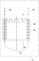
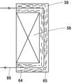
次に本発明の他の実施形態を図8〜図10を参照して説明する。磁気センサーに組み込まれる磁気回路構成部品は、偏平形状軟磁性粉末の長軸方向が磁気回路構成部品を通る磁力線方向にほぼ平行に配向して合成樹脂中に分散している偏平粉末含有磁性樹脂材料からなるものであり、この磁気回路構成部品について説明する。図8は、本発明の磁気センサーに組み込まれる磁気回路構成部品の1つである検出リングにおける偏平形状軟磁性粉末の配向性を示す断面説明図である。図9は、本発明の磁気センサーに組み込まれる磁気回路構成部品の1つであるヨークにおける偏平形状軟磁性粉末の配向性を示す断面説明図である。磁気センサーに組み込まれる磁気回路構成部品は、偏平形状軟磁性粉末64の長軸方向はいずれも磁気回路構成部品(検出リング54、ヨーク59)を通る磁力線60の方向に配向して合成樹脂65中に分散している。フェノール 等
前記偏平粉末含有磁性樹脂材料は、ポリイミド樹脂等の熱硬化性樹脂、或いはポリアミド樹脂、PPS(ポリフェニレンサルファイド)樹脂等の熱可塑性樹脂に扁平形状軟磁性粉末を30〜95体積%(一層好ましくは、50〜90体積%)含有させたものが好ましく、その理由は、30体積%未満では十分な透磁率が得られないからであり、一方、95体積%を越えて含有すると、十分な強度が得られないと共に、磁場成形を行った場合の扁平形状磁性粉末の配向性が阻害されるので好ましくない理由によるものである。さらに詳細に説明すると、図4(C)で示したような型成形の場合は、熱可塑性樹脂に扁平形状軟磁性粉末を30〜95体積%が好ましく、一方図4(A)で示したような射出成形においては、熱可塑性樹脂に扁平形状軟磁性粉末を30〜80体積%含有することが好ましい。また、フェノール樹脂の使用にあっては、図4(C)で示したような型成形が好ましい。さらに、図8において検出リング54のおけるニ点鎖線で示すような成形金型71において、磁力線60と同一或いはほぼ同一な方向Mの磁力線の磁場を配設して成形を行うことにより、偏平形状軟磁性粉末64は金型71に配設された磁場によって配向され成形を行うことができる。尚、この成形は図4(A)で示す射出成形或いは図4(B)で示す型形成などにより行われる。このように、磁界(磁場)条件下において樹脂65中の偏平形状軟磁性粉末64の長手方向を確実に磁場(磁界)の方向Mと平行に配向することができる。
【0052】
前記偏平粉末含有磁性樹脂材料に含まれる偏平形状軟磁性粉末は、通常散られている成分組成を有し、鉄粉末、FeーSi系鉄基軟磁性合金粉末、FeーAl系鉄基軟磁性合金粉末、FeーSiーAl系鉄基軟磁性合金粉末、FeーNi系鉄基軟磁性合金粉末、FeーCr系鉄基軟磁性合金粉末、FeーCo系鉄基軟磁性合金粉末等であり、一層具体的には、鉄粉末は純鉄粉末であり、FeーSi系鉄基軟磁性合金粉末は、Si:0.1〜10質量%を含有し、残部がFe及び不可避不純物からなるFeーSi系鉄基軟磁性合金粉末(例えば、Feー3%Siからなる組成を有するケイ素鋼粉末)であり、残部がFe及び不可避不純物からなる。
【0053】
FeーAl系鉄基軟磁性合金粉末は、Al:0.1〜20質量%を含有し、残部がFe及び不可避不純物からなるFeーAl系鉄基軟磁性合金粉末(例えばFeー15%Alからなる組成を有するアルバーム粉末)である。
【0054】
FeーSiーAl系鉄基軟磁性合金粉末は、Si:0.1〜10質量%、Al:0.1〜20質量%を含有し、残部がFe及び不可避不純物からなるFeーSiーAl系鉄基軟磁性合金粉末(例えばSi:9.5質量%、Al:5.5質量%を含有し、残部がFe及び不可避不純物かななる組成を有するセンダスト)である。
【0055】
FeーNi系鉄基軟磁性合金粉末は、Ni:35〜85質量%を含有し、必要に応じてMo:5質量%以下、Cu:5質量%以下、Cr:2質量%以下、Mn:0.5質量%以下の内の1種または2種以上を含有し、残部がFe及び不可避不純物からなるニッケル基軟性合金粉末(例えばFe−49%Ni粉末)である。
【0056】
FeーCr系鉄基軟磁性合金粉末は、Cr:1〜20質量%を含有し、必要に応じてAl:5質量%以下、Ni:5質量%以下の内の1種または2種を含有し、残部がFe及び不可避不純物からなるFeーCr系鉄基軟磁性合金粉末である。
【0057】
FeーCo系鉄基軟磁性合金粉末はCo:25〜60質量%を含有し、残部がFe及び不可避不純物からなる組成、またはCo:25〜60質量%、V0.5〜5質量%を含有し、残部がFe及び不可避不純物からなる組成を有するFe−Co系軟磁性合金粉末であることが好ましいが、特にこれらに限定されるものではない。
【0058】
前記偏平粉末含有磁性樹脂材料に含まれる偏平形状軟磁性粉末は、図10の断面図に示されるように、短軸長をa、長軸長をbとすると、アスペクト比(a/b)が0.4以下であり、かつ長軸長bが10μm以上、2mm以下であるように定めた。その理由は、アスペクト比が、0.5、好ましくは0.4を越えかつ長軸長をbが5μm、好ましくは10μmを下回わると十分な透磁率が得られなくなるからであり、長軸長bが5mm、好ましくは2mmを越えると成形が困難なケースや偏平形状軟磁性粉末の配向が困難となるケースが生じるからである。この磁気センサーにおける偏平粉末含有磁性樹脂材料に含まれるアスペクト比(a/b)が0.4以下でありかつ長軸長bが10μm以上、2mm以下である偏平形状軟磁性粉末64は、長軸長bの方向が磁力線60の方向に配向して合成樹脂中に分散し含有されていることが必要である。前記アスペクト比は偏平形状軟磁性粉末の粉末形状を特定するために一般に用いられるファクターであるから、これ以上の詳細な説明は省略する。
【0059】
前記磁気センサーに組込まれる偏平形状軟磁性粉末の長軸方向が磁気回路構成部品を通る磁力線方向にほぼ平行に配向して合成樹脂中に分散している偏平粉末含有磁性樹脂材料からなる磁気回路構成部品は、偏平形状軟磁性粉末を含む合成樹脂を射出成形すると、偏平形状軟磁性粉末が射出流れに沿って分散するところから製造することができるが、一方向に磁場をかけながら磁場成形することにより作製することが偏平形状軟磁性粉末の配向を確実に行うことができるので一層好ましい。
【0060】
例えば、図8の偏平形状軟磁性粉末64の長軸方向が検出リングの軸方向に平行に揃うように形成するには、磁力線60方向に磁場をかけながら紙面の上下方向に偏平粉末含有磁性樹脂材料をプレス成形することにより成形することができる。図9の偏平形状軟磁性粉末64の長軸方向がヨークを通過する磁力線60の方向に平行に揃うように成形するには、磁力線60方向に磁場をかけながら偏平粉末含有磁性樹脂材料をプレス成形することにより成形することができる。
【0061】
次に実施例1〜7および比較例1〜3について説明する。
【0062】
Si:9.5質量%、Al:5.5質量%を含有し、残部がFeおよび不可避不純物からなる組成を有するFe−Si−Al鉄基軟磁性合金を高周波溶解し、ガスアトマイズすることにより平均粒径:30〜120μmを有し、アスペクト比がほぼ1のガスアトマイズ粉末を作製した。
【0063】
このガスアトマイズ粉末をボールミルに装入し、回転量を調整することにより表1に示される異なるアスペクト比(a/b)(ただし、a:短軸長、b:長軸長とする)を有する偏平形状軟磁性粉末を作製し、これら偏平形状軟磁性粉末を表1に示される割合でPPS樹脂に配合し、混合して偏平粉末含有磁性樹脂材料A〜Jを作製し、これら偏平粉末含有磁性樹脂材料A〜Jを金型に充填し、磁場をリング状試験片の軸方向にかけながら磁場中プレス成形することにより偏平形状軟磁性粉末の長軸方向がリング状試験片の軸方向に配向し、外径:35mm、内径:25mm、高さ:10mmの寸法を有するリング状試験片を作製した。また同時に、このリング状試験片の軸方向に磁気回路を形成するためのコイルと内在する治具を同じ材料で作製した。そして、この磁気回路の一部を形作る治具の組織は、磁気回路に沿う様に偏平粉末を配向させた。
【0064】
これらのリング状試験片と治具を組付け、それぞれ周波数:0.1KHz、0.5KHz、0.8KHz、1KHz、5KHz、8KHz、10KHz、20KHz、50KHz、80KHz、100KHz、200KHz、500KHz、800KHzおよび1000KHzにおけるインダクタンスをインピーダンスアナライザーで測定し、その結果を表2に示すことにより実施例1〜7および比較例1〜3を実施した。
【0065】
【表1】
【表2】
比較例4
表1に示される偏平粉末含有磁性樹脂材料Dを射出成形用金型に充填し、磁場をリング状試験片の半径方向にかけながら磁場中プレス成形することにより偏平形状軟磁性粉末の長軸方向がリング状試験片の半径方向に配向し、外径:35mm、内径:25mm、高さ:10mmの寸法を有する比較リング試験片を作製した。また同時に、このリング状試験片の軸方向に磁気回路を形成するためのコイルを内在する治具を同じ材料を用いて作製し、そして、この磁気回路の一部を形作る治具の組織は、磁気回路に対して直角方向に偏平粉末を配向させた。このリング状試験片と治具を組付け、それぞれ周波数:0.1KHz、0.5KHz、0.8KHz、1KHz、5KHz、8KHz、10KHz、20KHz、50KHz、80KHz、100KHz、200KHz、500KHz、800KHzおよび1000KHzにおけるインダクタンスをインピーダンスアナライザーで測定し、その結果を表3に示すことにより比較例4を実施した。
【0068】
【表3】
実施例
実施例1〜7および比較例1〜3で作製した平均粒径:50μmを有し、アスペクト比がほぼ1のガスアトマイズ粉末:70体積%をPPS樹脂に配合し、混合してガスアトマイズ粉末含有磁性樹脂材料を作製し、これを金型に充填し、プレス形成することにより外形:35mm、内径:25mm、高さ:10mmの寸法を有するリング状試験片を作製した。また同時に、このリング状試験片の軸方向に磁気回路を形成するためのコイルを内在する治具を同じ材料を用いて作製した。このリング状試験片と治具を組付け、それぞれ周波数:0.1KHz、0.5KHz、0.8KHz、1KHz、5KHz、8KHz、10KHz、20KHz、50KHz、80KHz、100KHz、200KHz、500KHz、800KHzおよび1000KHzにおけるインダクタンスをインビーダンスアナライザーで測定し、その結果を表4に示すことにより従来例を実施した。
【0070】
【表4】
表1〜2および表4に示される結果から、実施例1〜7で作製したリング状試験片1〜7は比較例1〜3で作製したリング状試験片および従来例で作製したリング状試験片に比べて、各周波数における比透磁率が格段に優れていることが分かる。さらに、比較例4および表3から磁力線に対して偏平形状軟磁性粉末が直角方向に配向したリング状試験片は比透磁率が格段に劣ることが分かる。
【0072】
これら効果を一層理解しやすくするために、実施例4で作製したリング状試験片、比較例4で作製したリング状試験片および従来例で作製したリング状試験片についての各周波数における比透磁率の測定結果を、縦軸に比透磁率をとり、横軸に周波数をとってグラフを作成し、そのグラフを図4に示した。この図4に示されるグラフからも実施例4で作製したリング状試験片は、従来例で作製したリング状試験片で作製したリング状試験片に比べて比透磁率が高いことが分かる。しかし、磁力線に対して偏平形状軟磁性粉末が直角方向に配向した比較例4のリング状試験片は比透磁率が格段に劣ることが一層明瞭に分かる。
【0073】
以上のように前記磁気センサーにおいては、磁性樹脂材料に含まれる軟磁性粉末を偏平形状軟磁性粉末64とし、この偏平形状軟磁性粉末64の長軸方向が磁力線60方向に平行に配合して剛性樹脂中に分散している偏平粉末含有磁性材料からなる磁気回路構成部品は、検出精度を上げるために周波数を高くしても比透磁率が低下することが極めて少なく優れた検出精度を示すことができる。
【0074】
さらに、前記偏平粉末含有磁性樹脂材料は、熱可塑性樹脂に扁平形状軟磁性粉末を30〜95体積%含有させたことにより、十分な透磁率が得られる共に、十分な強度も得られる。
【0075】
また、前記偏平粉末含有磁気樹脂材料に含まれる扁平形状軟磁性粉末64は、短軸長をa、長軸長をbとするとアスペクト比(a/b)が0.4以下でありかつ長軸長bが10μm以上、2mm以下である偏平形状軟磁性粉末とすることで、十分な透磁率が得られ、また偏平形状軟磁性粉末の配向を容易に行うことができる。
【0076】
尚、本発明は上記実施形態に限定されるものではなく、本発明の要旨の範囲内において、種々の変形実施が可能である。例えば磁気回路構成部品は、ヨークの他に検出子等でもよい。
【0077】
【発明の効果】
請求項1の発明は、樹脂中に磁性金属粉体を設けて磁界に配置される磁性材であって、前記磁性金属粉体は偏平形状に形成され、隣接するそれぞれの前記磁性金属粉体の長手方向を相互にほぼ平行に配向するとともに、前記磁性金属粉体の長手方向を前記磁界の磁力線とほぼ平行に配向したことを特徴とする磁性材であり、磁性金属粉体を用いた磁性材であっても、透磁率を向上することができる。また、磁性材の形状の自由度も向上できる。さらに前記磁性金属粉体の長手方向を前記磁界の磁力線とほぼ平行に配向したことで、各種磁気回路等に有効に利用することができる。
【0078】
請求項2の発明は、樹脂中に磁性金属粉体を設けて屈曲方向に磁界が配置される磁性材の角部において、前記磁性金属粉体は偏平形状に形成され、前記磁性金属粉体の長手方向を屈曲した前記磁界の磁力線とほぼ平行に配向したことを特徴とする磁性材であり、角部においても磁力線を連続的に配置することができる。
【0079】
請求項3の発明は、樹脂中に磁性金属粉体を設ける磁性材であって、前記磁性金属粉体は偏平形状に形成され、隣接するそれぞれの前記磁性金属粉体の長手方向を相互にほぼ平行になるように配向する磁性材の製造方法において、前記磁性金属粉体を樹脂と共に金型のキャビティに射出して成形を行うことを特徴とする磁性材の製造方法であり、透磁率の高い磁性材を製造でき、またその形状の自由度も高くすることができる。
【0080】
請求項4の発明は、前記射出時における前記キャビティ内の前記磁性金属粉体と樹脂を一方向の流れとすることを特徴とする請求項3記載の磁性材の製造方法であり、磁性金属粉体はその長手方向が一方向に規制されて配向することができる。
【0081】
請求項5の発明は、樹脂中に磁性金属粉体を設けて磁界に配置される磁性材であって、前記磁性金属粉体は偏平形状に形成され、隣接するそれぞれの前記磁性金属粉体の長手方向を相互にほぼ平行になるように配向する磁性材の製造方法において、前記磁性金属粉体と樹脂を金型のキャビティに射出して成形を行い、前記射出時における前記キャビティ内の前記磁性金属粉体と樹脂を一方向の流れとし、かつ前記一方向の流れを前記磁界の磁力線とほぼ平行になるようにしたことを特徴とする磁性材の製造方法であり、磁性金属粉体はその長手方向が一方向に規制されて配向することができ、また各種磁気回路等に有効に利用することができる。
【0082】
さらに、請求項6の発明は、前記金型に磁場を配設して射出することを特徴とする請求項3〜5のいずれか1項に記載の磁性材の製造方法であり、前記配向を磁場によっても確実に形成することができる。
【0083】
また、請求項7の発明は、前記金型内にコイルを配置し、前記磁性金属粉体と樹脂を金型のキャビティに射出して一体成形することを特徴とする請求項3〜5のいずれか1項に記載の磁性材の製造方法であり、コイル内蔵のものを容易に製造することができる。
【0084】
さらに、請求項8の発明は、樹脂中に磁性金属粉体を設ける磁性材であって、前記磁性金属粉体は偏平形状に形成され、隣接するそれぞれの前記磁性金属粉体の長手方向を相互にほぼ平行になるように配向する磁性材の製造方法において、前記磁性金属粉体と樹脂を型開状態の金型に収容した後、型閉して金型成形を行うときに前記金型に磁場を配設して成形を行うことを特徴とする磁性材の製造方法であり、前記配向を磁場によっても確実に形成することができる。
【0085】
さらに、請求項9の発明は、合成樹脂中に偏平形状軟磁性粉末が分散して含まれる磁性樹脂材料で構成された磁気回路を構成する磁気回路構成部品が組込まれ、前記磁気回路構成部品を通る磁力線の変化に基づいて変位を検出する磁気センサーであって、前記磁性樹脂材料に含まれる前記偏平形状軟磁性粉末は長軸方向が前記磁気回路構成部品を通る磁力線にほぼ平行に配向していることを特徴とする磁気であり、比透磁率が高くかつ高周波を高くしても比透磁率の変化が少ない磁気回路構成部品を提供することができ、この優れた磁気回路構成部品を磁気センサーに組込むことにより一層優れた磁気センサーを提供することができ、とくに自動車産業において優れた効果をもたらすものである。
【0086】
請求項10の発明は、合成樹脂中に偏平形状軟磁性粉末が分散して含まれる磁性樹脂材料で構成された磁気回路を構成する磁気回路構成部品が組込まれ、前記磁気回路構成部品を通る磁力線の変化に基づいて変位を検出する磁気センサーであって、前記磁気回路構成部品は前記合成樹脂中に前記偏平形状軟磁性粉末:30〜95体積%を含む偏平粉末含有磁性樹脂材料からなり、かつ前記偏平粉末含有磁性樹脂材料に含まれる前記偏平形状軟磁性粉末は長軸方向が前記磁気回路構成部品を通る磁力線にほぼ平行に配向していることを特徴とする磁気センサーであり、十分な透磁率が得られる共に、十分な強度も得られる。
【0087】
請求項11の発明は、前記樹脂材料に含まれる前記偏平形状軟磁性粉末は、短軸長をa、長軸長をbとするとアスペクト比(a/b)が0.4以下であり、かつ長軸長bが10μm以上、2mm以下であることを特徴とする請求項9記載の磁気センサーであり、十分な透磁率が得られ、また偏平形状軟磁性粉末の配向を容易に行うことができる。
【0088】
請求項12、13に記載の発明においては、前記磁気回路構成部品は、検出子、ヨークであり、これら透磁率を向上することができる。
【図面の簡単な説明】
【図1】本発明の第1実施形態を示す一部切り欠き斜視図である。
【図2】本発明の第1実施形態を示す圧粉体の製造を示す断面図である。
【図3】本発明の第1実施形態を示す第1コイル収納部材の一部を拡大した断面図である。
【図4】本発明の第1実施形態を示す金型装置の断面図であり、図4(A)は射出成形の場合の断面図、図4(B)はコイルをインサート成形する場合の断面図、図4(C)は型成形の断面図である。
【図5】本発明の第1実施形態を示す磁性材の拡大写真である。
【図6】本発明の第1実施形態を示す交流磁気特性グラフである。
【図7】本発明の第2実施形態を示す一部切り欠き斜視図である。
【図8】本発明の第3実施形態を示す磁気センサーに組込まれる検出リングに含まれて偏平形状軟磁性粉末の配向状態を示す断面説明図である。
【図9】本発明の第3実施形態を示す磁気センサーに組込まれるヨーク含まれる偏平形状軟磁性粉末の配向状態を示す断面説明図である。
【図10】本発明の第3実施形態を示す偏平形状軟磁性粉末におけるアスペクト比と配向性を説明するための説明図である。
【図11】従来の磁気センサーを示す一部切り欠き斜視図である。
【図12】従来の磁気センサーの断面図である。
【符号の説明】
6 コイル
8C 角部
31A,31B,31C,32 磁性金属粉体
33,34 樹脂
42,45 金型
46 キャビティ
54 検出リング(磁気回路構成部品)
59 ヨーク(磁気回路構成部品)
60 Y 磁力線
65 合成樹脂
X,X´ 長手方向
Z 樹脂の流れ[0001]
TECHNICAL FIELD OF THE INVENTION
The present invention relates to a magnetic material that magnetizes when placed in a magnetic field, a method of manufacturing the same, and a magnetic sensor in an electric power steering for an automobile that applies a steering assisting force according to, for example, a steering torque, and a magnetic circuit incorporated in the magnetic sensor Related to parts.
[0002]
[Prior art]
For example, silicon steel in which silicon is mixed with iron is well known as a magnetic material. And such a silicon steel strip is wound and laminated in an annular shape to form a wound iron core. A dust core is well known as a magnetic core material mainly used in communication circuits such as radios and televisions. The dust core is formed by forming a magnetic metal into a powder, covering the surface with an insulating layer, and compressing the solid with a binder.
[0003]
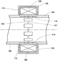
In addition, as shown in FIGS. 11 and 12, a magnetic sensor in a conventional electric power steering of an automobile connects an
[0004]
On the other hand, a
[0005]
When a torque is applied to the
[0006]
The rotation of the
[0007]
Conventionally, a circuit component (hereinafter, referred to as a magnetic circuit component) in which lines of magnetic force pass through the
[0008]
Therefore, a magnetic resin material containing 80 to 95% by mass of a soft magnetic powder in a synthetic resin has a characteristic that the relative magnetic permeability does not become extremely low like a metal material even when the frequency is increased. Proposals have been made to produce magnetic circuit components of a magnetic sensor, particularly a synthetic resin comprising a large-sized soft magnetic powder having a particle size of 2 μm or more and a small-sized paramagnetic powder having a particle size of 0.05 μm or less. A magnetic circuit component made of a magnetic resin material containing 80 to 95% by mass of a magnetic powder is said to have an excellent effect (see Patent Document 1).
[0009]
[Patent Document 1]
JP 2000-292275 A
[0010]
[Problems to be solved by the invention]
The magnetic material formed by laminating steel strips as described above can improve the relative magnetic permeability, but has a problem in that the degree of freedom in shape is poor. Further, in the above-mentioned dust core, although the degree of freedom of the shape is improved, the relative permeability is limited.
[0011]
The soft magnetic powder in the above-described magnetic sensor has an excellent characteristic that the change in relative permeability is extremely small even when the frequency is increased, but the conventional magnetic resin material has a low relative permeability itself. However, the detection accuracy of a magnetic sensor incorporating a magnetic circuit component made of a magnetic resin material has not been satisfactory.
[0012]
Accordingly, an object of the present invention is to provide a magnetic material capable of increasing the degree of freedom in shape and the relative magnetic permeability, and a method for manufacturing the same. In addition, the present invention develops a magnetic circuit component having a characteristic in which the relative magnetic permeability does not decrease even when the frequency is increased, and has a higher relative magnetic permeability. It is an object of the present invention to provide a magnetic sensor using a magnetic material having excellent characteristics and a magnetic circuit component incorporated in the magnetic sensor.
[0013]
[Means for Solving the Problems]
The invention according to
[0014]
According to the structure of the first aspect, the magnetic metal powder is formed in a flat shape, and its longitudinal direction is oriented substantially parallel to each other to improve the magnetic permeability. Is placed in a resin and molded. Further, the longitudinal direction of the magnetic metal powder is oriented substantially parallel to the magnetic field lines of the magnetic field.
[0015]
The invention according to claim 2 is that the magnetic metal powder is formed in a flat shape at a corner of the magnetic material where a magnetic metal powder is provided in a resin and a magnetic field is arranged in a bending direction. A magnetic material characterized in that it is oriented substantially parallel to the magnetic field lines of the magnetic field whose longitudinal direction is bent.
[0016]
According to the configuration of the second aspect, the magnetic metal powder is formed in a flat shape, and its longitudinal direction is oriented substantially parallel to each other, so that the magnetic permeability can be improved at the corners.
[0017]
The invention according to
[0018]
According to this configuration, by injecting the magnetic metal powder into the mold cavity together with the resin, the flat magnetic metal powder receives resistance due to the flow of the molten resin and its longitudinal direction is regulated. Thus, the magnetic metal powder can be arranged in the resin in a uniform direction.
[0019]
The invention according to claim 4 is the method according to
[0020]
According to the configuration of the fourth aspect, the magnetic metal powder and the resin in the cavity are formed in a one-way flow in which the resin does not come into contact with each other by turning back or the like, thereby allowing the one-way flow of the molten resin. As a result, the flat-shaped magnetic metal powder receives resistance.
[0021]
The invention according to
[0022]
According to the configuration of the fifth aspect, the magnetic metal powder and the resin in the cavity are returned in a one-way flow such as swirling so that the resins do not come into contact with each other. As a result, the flat-shaped magnetic metal powder receives resistance. Further, the flow of the magnetic metal powder in one direction is oriented substantially parallel to the magnetic field lines of the magnetic field.
[0023]
The invention according to
[0024]
According to this configuration, the magnetic metal powder can be injection-molded by being oriented by the magnetic field provided in the mold.
[0025]
The invention according to
[0026]
According to this configuration, the magnetic metal powder can be formed integrally with the coil.
[0027]
The invention according to
[0028]
According to this configuration, the magnetic metal powder can be injection-molded while being oriented by the magnetic field provided in the mold.
[0029]
Also, (a) a magnetic sensor which incorporates a magnetic circuit component made of a magnetic resin material in which soft magnetic powder is dispersed and contained in a synthetic resin, and detects a change in a magnetic field line passing through the magnetic circuit component, The soft magnetic powder contained in the magnetic resin material is a flat-shaped soft magnetic powder, and the long axis direction of the flat-shaped soft magnetic powder is blended in parallel with the direction of the magnetic force and dispersed in the synthetic resin. A magnetic circuit component made of a flat powder-containing magnetic material) has a very low relative permeability even if the frequency is increased in order to increase the detection accuracy. Shows better detection accuracy.
(B) The flat soft magnetic powder contained in the flat powder-containing magnetic resin material has an aspect ratio (a / b) of 0.4 or less and a long axis, where a is the short axis length and b is the long axis length. Research that flat soft magnetic powder having a length b of 10 μm or more and 2 mm or less is preferable, and it is preferable that the flat soft magnetic powder be dispersed and contained in synthetic resin in an amount of 30 to 95% by volume. Based on the results,
According to a ninth aspect of the present invention, there is provided a magnetic circuit component constituting a magnetic circuit formed of a magnetic resin material in which flat soft magnetic powder is dispersed and contained in a synthetic resin, and magnetic lines of force passing through the magnetic circuit component A magnetic sensor that detects displacement based on a change in the magnetic circuit component, wherein the magnetic circuit component is made of a flat powder-containing magnetic resin material containing a flat-shaped soft magnetic powder in a synthetic resin, and The flat-shaped soft magnetic powder contained in the magnetic sensor is characterized in that the major axis direction is oriented substantially parallel to the line of magnetic force passing through the component.
[0030]
According to a tenth aspect of the present invention, there is provided a magnetic circuit component constituting a magnetic circuit formed of a magnetic resin material in which flat soft magnetic powder is dispersed and contained in a synthetic resin, and magnetic lines of force passing through the magnetic circuit component A magnetic sensor for detecting displacement based on a change in the flat magnetic powder, wherein the magnetic circuit component is made of a flat-powder-containing magnetic resin material containing 30 to 95% by volume of a flat soft magnetic powder in a synthetic resin; The flat-shaped soft magnetic powder contained in the powder-containing magnetic resin material is a magnetic sensor characterized in that the major axis direction is oriented substantially parallel to the line of magnetic force passing through the component.
[0031]
An eleventh aspect of the present invention is that the flat soft magnetic powder contained in the resin material has an aspect ratio (a / b) of 0.4 or less, where a is a short axis length and b is a long axis length, and 10. The magnetic sensor according to claim 9, wherein the major axis length b is 10 μm or more and 2 mm or less.
[0032]
The magnetic circuit components incorporated in the magnetic sensor are, specifically, a detection ring and a yoke having a U-shaped cross section. At least a portion of these magnetic circuit components through which the magnetic force lines pass must be oriented substantially parallel to the magnetic force lines such that the major axis directions of the flat soft magnetic powder are aligned. Therefore, in the twelfth aspect of the present invention, the magnetic circuit component is a magnetic sensor according to any one of the ninth to eleventh aspects, and the thirteenth aspect of the present invention. The magnetic sensor according to any one of claims 9 to 11, wherein the magnetic circuit component is a yoke.
[0033]
DETAILED DESCRIPTION OF THE INVENTION
Hereinafter, an embodiment of the present invention will be described with reference to FIGS. The embodiment shows an example of a coil housing member of a detection coil used for a non-contact displacement sensor as a magnetic sensor of an electric power steering device of an automobile. As shown in FIG. 1, the non-contact type displacement sensor connects an
[0034]
The first
[0035]
The first, second, and third detection rings 4, 5 and a
[0036]
Further, a
[0037]
As shown in FIG. 1, an outer
[0038]
Then, with the above configuration, the
[0039]
Then, the magnetic field lines Y of the magnetic field formed between the first and second detection rings 4 and 5 and the adjacent
[0040]
Next, a method of manufacturing the part where the outer
[0041]
Thus, at the time of the production, when the magnetic metal powder 31 and the thermoplastic
[0042]
FIG. 5 is a 400 times enlarged photograph of the magnetic material, and it was found that the magnetic metal powders 31 shown in white were arranged in parallel with each other in the
[0043]
When a portion where the outer
[0044]
Further, the
[0045]
As described above, in the above embodiment, the magnetic material provided with the
[0046]
The
[0047]
Further, a magnetic material provided with
[0048]
Further, the
[0049]
Further, the
[0050]
Moreover, if the
[0051]
Next, another embodiment of the present invention will be described with reference to FIGS. The magnetic circuit component incorporated in the magnetic sensor is a flat powder-containing magnetic resin material in which the major axis direction of the flat soft magnetic powder is oriented substantially parallel to the direction of the magnetic force passing through the magnetic circuit component and dispersed in the synthetic resin. This magnetic circuit component will be described. FIG. 8 is an explanatory cross-sectional view showing the orientation of a flat soft magnetic powder in a detection ring which is one of the magnetic circuit components incorporated in the magnetic sensor of the present invention. FIG. 9 is an explanatory sectional view showing the orientation of the flat soft magnetic powder in the yoke which is one of the magnetic circuit components incorporated in the magnetic sensor of the present invention. The magnetic circuit components incorporated in the magnetic sensor are arranged such that the major axis direction of the flat-shaped soft
The flat powder-containing magnetic resin material is a thermosetting resin such as a polyimide resin, or a thermoplastic resin such as a polyamide resin or a PPS (polyphenylene sulfide) resin, and a flat soft magnetic powder containing 30 to 95% by volume (more preferably, (50-90% by volume) is preferable because sufficient magnetic permeability cannot be obtained if the content is less than 30% by volume, while sufficient strength is obtained if the content exceeds 95% by volume. This is not preferable because the orientation of the flat magnetic powder when magnetic field molding is performed is impaired. More specifically, in the case of molding as shown in FIG. 4 (C), the flat soft magnetic powder is preferably contained in the thermoplastic resin in an amount of 30 to 95% by volume, while as shown in FIG. 4 (A). In the injection molding, it is preferable that the thermoplastic resin contains the flat soft magnetic powder in an amount of 30 to 80% by volume. Further, when using a phenol resin, a molding as shown in FIG. 4C is preferable. Further, in a
[0052]
The flat-shaped soft magnetic powder contained in the flat-powder-containing magnetic resin material has a component composition that is usually dispersed, and includes iron powder, Fe-Si-based iron-based soft magnetic alloy powder, and Fe-Al-based iron-based soft magnetic powder. Alloy powder, Fe-Si-Al-based soft magnetic alloy powder, Fe-Ni-based soft magnetic alloy powder, Fe-Cr-based soft magnetic alloy powder, Fe-Co-based soft magnetic alloy powder, etc. Yes, more specifically, the iron powder is pure iron powder, and the Fe-Si-based iron-based soft magnetic alloy powder contains 0.1 to 10% by mass of Si, with the balance being Fe and unavoidable impurities. Fe-Si based iron-based soft magnetic alloy powder (for example, silicon steel powder having a composition of Fe-3% Si), the balance being Fe and unavoidable impurities.
[0053]
The Fe-Al-based iron-based soft magnetic alloy powder contains 0.1 to 20% by mass of Al and the balance is Fe-Al-based iron-based soft magnetic alloy powder (for example, Fe-15% Al). (Albam powder having a composition consisting of:
[0054]
The Fe-Si-Al-based iron-based soft magnetic alloy powder contains 0.1 to 10% by mass of Si and 0.1 to 20% by mass of Al, and the remainder is Fe-Si-Al composed of Fe and inevitable impurities. This is an iron-based soft magnetic alloy powder (for example, Sendust containing 9.5% by mass of Si and 5.5% by mass of Al, with the balance being Fe and unavoidable impurities).
[0055]
The Fe-Ni-based iron-based soft magnetic alloy powder contains 35 to 85% by mass of Ni, and if necessary, Mo: 5% by mass or less, Cu: 5% by mass or less, Cr: 2% by mass or less, Mn: It is a nickel-based soft alloy powder (for example, Fe-49% Ni powder) containing one or more of 0.5% by mass or less, and the balance being Fe and unavoidable impurities.
[0056]
The Fe-Cr-based iron-based soft magnetic alloy powder contains 1 to 20% by mass of Cr, and optionally contains one or two of Al: 5% by mass or less and Ni: 5% by mass or less. The balance is Fe-Cr based iron-based soft magnetic alloy powder composed of Fe and inevitable impurities.
[0057]
Fe-Co-based iron-based soft magnetic alloy powder contains Co: 25 to 60% by mass, and the balance is composed of Fe and unavoidable impurities, or Co: 25 to 60% by mass, and V: 0.5 to 5% by mass. Preferably, the balance is Fe-Co-based soft magnetic alloy powder having a composition of Fe and unavoidable impurities, but is not particularly limited thereto.
[0058]
As shown in the cross-sectional view of FIG. 10, the flat soft magnetic powder contained in the flat powder-containing magnetic resin material has an aspect ratio (a / b) where a is the short axis length and b is the long axis length. 0.4 or less, and the major axis length b was determined to be 10 μm or more and 2 mm or less. The reason is that if the aspect ratio exceeds 0.5, preferably 0.4, and the major axis length b is less than 5 μm, preferably less than 10 μm, sufficient magnetic permeability cannot be obtained. If the length b exceeds 5 mm, preferably more than 2 mm, there are cases where molding is difficult and cases where orientation of the flat soft magnetic powder becomes difficult. The flat-shaped soft
[0059]
A magnetic circuit configuration comprising a flat powder-containing magnetic resin material in which the major axis direction of the flat-shaped soft magnetic powder incorporated in the magnetic sensor is oriented substantially parallel to the direction of the magnetic field passing through the magnetic circuit components and dispersed in the synthetic resin. Parts can be manufactured by injection molding synthetic resin containing flat-shaped soft magnetic powder from the point where the flat-shaped soft magnetic powder is dispersed along the injection flow.However, magnetic field forming is performed while applying a magnetic field in one direction. It is more preferable to produce the soft magnetic powder because it can surely orient the flat soft magnetic powder.
[0060]
For example, in order to form the long axis direction of the flat soft
[0061]
Next, Examples 1 to 7 and Comparative Examples 1 to 3 will be described.
[0062]
An Fe-Si-Al iron-based soft magnetic alloy containing 9.5% by mass of Si and 5.5% by mass of Al and having the balance of Fe and unavoidable impurities is subjected to high-frequency melting and gas atomization to obtain an average. A gas atomized powder having a particle size of 30 to 120 μm and an aspect ratio of almost 1 was produced.
[0063]
This gas atomized powder was charged into a ball mill and the amount of rotation was adjusted to obtain a flattened sheet having different aspect ratios (a / b) (a: short axis length, b: long axis length) as shown in Table 1. Soft magnetic powders having a shape are prepared, and these soft magnetic powders having a flat shape are blended with a PPS resin at a ratio shown in Table 1 and mixed to prepare magnetic resin materials A to J containing the flat powder. The materials A to J are filled in a mold, and the long axis direction of the flat-shaped soft magnetic powder is oriented in the axial direction of the ring-shaped test piece by press-forming in a magnetic field while applying a magnetic field in the axial direction of the ring-shaped test piece. A ring-shaped test piece having dimensions of outer diameter: 35 mm, inner diameter: 25 mm, and height: 10 mm was prepared. At the same time, a coil for forming a magnetic circuit in the axial direction of the ring-shaped test piece and an internal jig were made of the same material. The structure of the jig forming a part of the magnetic circuit oriented the flat powder along the magnetic circuit.
[0064]
Assembling these ring-shaped test pieces and jigs, respectively: frequencies: 0.1 KHz, 0.5 KHz, 0.8 KHz, 1 KHz, 5 KHz, 8 KHz, 10 KHz, 20 KHz, 50 KHz, 80 KHz, 100 KHz, 200 KHz, 500 KHz, 800 KHz and Inductance at 1000 KHz was measured with an impedance analyzer, and the results are shown in Table 2. Examples 1 to 7 and Comparative Examples 1 to 3 were performed.
[0065]
[Table 1]
[Table 2]
Comparative Example 4
A flat powder-containing magnetic resin material D shown in Table 1 is filled in an injection molding die, and the long axis direction of the flat soft magnetic powder is formed by press molding in a magnetic field while applying a magnetic field in the radial direction of the ring-shaped test piece. A comparative ring test piece oriented in the radial direction of the ring-shaped test piece and having dimensions of an outer diameter: 35 mm, an inner diameter: 25 mm, and a height: 10 mm was prepared. At the same time, a jig containing a coil for forming a magnetic circuit in the axial direction of the ring-shaped test piece is manufactured using the same material, and the structure of the jig forming a part of the magnetic circuit is as follows. The flat powder was oriented perpendicular to the magnetic circuit. The ring-shaped test piece and the jig are assembled, and the frequencies are respectively 0.1 KHz, 0.5 KHz, 0.8 KHz, 1 KHz, 5 KHz, 8 KHz, 10 KHz, 20 KHz, 50 KHz, 80 KHz, 100 KHz, 200 KHz, 500 KHz, 800 KHz and 1000 KHz. Was measured by an impedance analyzer, and the results are shown in Table 3. Comparative Example 4 was performed.
[0068]
[Table 3]
Example
A gas atomized powder having an average particle diameter of 50 μm and an aspect ratio of approximately 1 prepared in Examples 1 to 7 and Comparative Examples 1 to 3 was mixed with a PPS resin by 70% by volume and mixed with a gas atomized powder-containing magnetic resin. A material was prepared, filled in a mold, and press-formed to produce a ring-shaped test piece having an outer diameter of 35 mm, an inner diameter of 25 mm, and a height of 10 mm. At the same time, a jig including a coil for forming a magnetic circuit in the axial direction of the ring-shaped test piece was manufactured using the same material. The ring-shaped test piece and the jig are assembled, and the frequencies are 0.1 KHz, 0.5 KHz, 0.8 KHz, 1 KHz, 5 KHz, 8 KHz, 10 KHz, 20 KHz, 50 KHz, 80 KHz, 100 KHz, 200 KHz, 500 KHz, 800 KHz and 1000 KHz, respectively. Was measured with an impedance analyzer, and the results are shown in Table 4.
[0070]
[Table 4]
From the results shown in Tables 1-2 and 4, the ring-shaped test pieces 1-7 prepared in Examples 1-7 are the ring-shaped test pieces prepared in Comparative Examples 1-3 and the ring-shaped test prepared in the conventional example. It can be seen that the relative permeability at each frequency is much better than that of the piece. Further, from Comparative Example 4 and Table 3, it can be seen that the ring-shaped test piece in which the soft magnetic powder having a flat shape is oriented in the direction perpendicular to the magnetic field lines has a remarkably inferior relative permeability.
[0072]
In order to make these effects easier to understand, the relative magnetic permeability at each frequency of the ring-shaped test piece manufactured in Example 4, the ring-shaped test piece manufactured in Comparative Example 4, and the ring-shaped test piece manufactured in the conventional example A graph was prepared from the results of the measurement, with the relative magnetic permeability taken on the vertical axis and the frequency taken on the horizontal axis, and the graph is shown in FIG. From the graph shown in FIG. 4, it can be seen that the relative permeability of the ring-shaped test piece manufactured in Example 4 is higher than that of the ring-shaped test piece manufactured in the conventional example. However, it can be clearly seen that the ring-shaped test piece of Comparative Example 4 in which the soft magnetic powder having a flat shape oriented in the direction perpendicular to the magnetic field lines had a significantly lower relative magnetic permeability.
[0073]
As described above, in the magnetic sensor, the soft magnetic powder contained in the magnetic resin material is made into the flat-shaped soft
[0074]
Further, in the flat powder-containing magnetic resin material, a sufficient soft magnetic permeability and a sufficient strength can be obtained by adding 30 to 95% by volume of the flat soft magnetic powder to the thermoplastic resin.
[0075]
The flat soft
[0076]
Note that the present invention is not limited to the above-described embodiment, and various modifications can be made within the scope of the present invention. For example, the magnetic circuit component may be a detector in addition to the yoke.
[0077]
【The invention's effect】
The invention according to
[0078]
The invention according to claim 2 is that the magnetic metal powder is formed in a flat shape at a corner of the magnetic material where a magnetic metal powder is provided in a resin and a magnetic field is arranged in a bending direction. The magnetic material is characterized in that it is oriented substantially parallel to the magnetic field lines of the magnetic field whose longitudinal direction is bent, and the magnetic field lines can be continuously arranged even at the corners.
[0079]
The invention according to
[0080]
The invention according to claim 4 is the method for manufacturing a magnetic material according to
[0081]
The invention according to
[0082]
Further, the invention according to
[0083]
The invention according to
[0084]
Further, the invention according to
[0085]
Further, according to the ninth aspect of the present invention, a magnetic circuit component constituting a magnetic circuit made of a magnetic resin material containing a flat soft magnetic powder dispersedly contained in a synthetic resin is incorporated, and the magnetic circuit component is A magnetic sensor that detects displacement based on a change in a magnetic field line passing therethrough, wherein the flat soft magnetic powder included in the magnetic resin material is oriented such that a major axis direction is substantially parallel to a magnetic field line passing through the magnetic circuit component. A magnetic circuit component having a high relative permeability and a small change in relative magnetic permeability even when the high frequency is increased. Incorporation in a helium can provide a more excellent magnetic sensor, and can provide excellent effects particularly in the automobile industry.
[0086]
According to a tenth aspect of the present invention, there is provided a magnetic circuit component constituting a magnetic circuit formed of a magnetic resin material in which flat soft magnetic powder is dispersed and contained in a synthetic resin, and magnetic lines of force passing through the magnetic circuit component A magnetic sensor for detecting a displacement based on a change in the soft magnetic powder, wherein the magnetic circuit component is made of a magnetic resin material containing a flat powder containing 30 to 95% by volume of the flat soft magnetic powder in the synthetic resin, and The flat-shaped soft magnetic powder contained in the flat-powder-containing magnetic resin material is a magnetic sensor characterized in that a major axis direction is oriented substantially parallel to a magnetic line of force passing through the magnetic circuit component. Not only can the magnetic susceptibility be obtained, but also sufficient strength can be obtained.
[0087]
An eleventh aspect of the present invention is that the flat soft magnetic powder contained in the resin material has an aspect ratio (a / b) of 0.4 or less, where a is a short axis length and b is a long axis length, and 10. The magnetic sensor according to claim 9, wherein the major axis length b is 10 μm or more and 2 mm or less, sufficient magnetic permeability is obtained, and orientation of the flat-shaped soft magnetic powder can be easily performed. .
[0088]
In the twelfth and thirteenth aspects, the magnetic circuit components are a detector and a yoke, and these magnetic permeability can be improved.
[Brief description of the drawings]
FIG. 1 is a partially cutaway perspective view showing a first embodiment of the present invention.
FIG. 2 is a cross-sectional view illustrating the production of a green compact according to the first embodiment of the present invention.
FIG. 3 is an enlarged cross-sectional view of a part of a first coil housing member according to the first embodiment of the present invention.
4A and 4B are cross-sectional views of a mold apparatus according to a first embodiment of the present invention, wherein FIG. 4A is a cross-sectional view in the case of injection molding, and FIG. FIG. 4 (C) is a sectional view of the molding.
FIG. 5 is an enlarged photograph of a magnetic material showing the first embodiment of the present invention.
FIG. 6 is an alternating current magnetic characteristic graph showing the first embodiment of the present invention.
FIG. 7 is a partially cutaway perspective view showing a second embodiment of the present invention.
FIG. 8 is an explanatory sectional view showing an orientation state of a flat soft magnetic powder included in a detection ring incorporated in a magnetic sensor according to a third embodiment of the present invention.
FIG. 9 is an explanatory sectional view showing an orientation state of a flat soft magnetic powder included in a yoke incorporated in a magnetic sensor according to a third embodiment of the present invention.
FIG. 10 is an explanatory diagram for explaining an aspect ratio and an orientation in a flat soft magnetic powder according to a third embodiment of the present invention.
FIG. 11 is a partially cutaway perspective view showing a conventional magnetic sensor.
FIG. 12 is a sectional view of a conventional magnetic sensor.
[Explanation of symbols]
6 coils
8C corner
31A, 31B, 31C, 32 Magnetic metal powder
33,34 resin
42,45 mold
46 cavities
54 Detection ring (Magnetic circuit component)
59 Yoke (magnetic circuit component)
60 Y magnetic field lines
65 Synthetic resin
X, X 'longitudinal direction
Flow of Z resin
Claims (13)
Priority Applications (1)
| Application Number | Priority Date | Filing Date | Title |
|---|---|---|---|
| JP2003153387A JP2004128455A (en) | 2002-08-02 | 2003-05-29 | Magnetic material, method for manufacturing the same, magnetic sensor using magnetic material, and magnetic circuit component incorporated in the magnetic sensor |
Applications Claiming Priority (2)
| Application Number | Priority Date | Filing Date | Title |
|---|---|---|---|
| JP2002226689 | 2002-08-02 | ||
| JP2003153387A JP2004128455A (en) | 2002-08-02 | 2003-05-29 | Magnetic material, method for manufacturing the same, magnetic sensor using magnetic material, and magnetic circuit component incorporated in the magnetic sensor |
Publications (1)
| Publication Number | Publication Date |
|---|---|
| JP2004128455A true JP2004128455A (en) | 2004-04-22 |
Family
ID=32300809
Family Applications (1)
| Application Number | Title | Priority Date | Filing Date |
|---|---|---|---|
| JP2003153387A Pending JP2004128455A (en) | 2002-08-02 | 2003-05-29 | Magnetic material, method for manufacturing the same, magnetic sensor using magnetic material, and magnetic circuit component incorporated in the magnetic sensor |
Country Status (1)
| Country | Link |
|---|---|
| JP (1) | JP2004128455A (en) |
Cited By (9)
| Publication number | Priority date | Publication date | Assignee | Title |
|---|---|---|---|---|
| JP2005184916A (en) * | 2003-12-17 | 2005-07-07 | Sumitomo Electric Ind Ltd | Dust core and stator core |
| WO2009028247A1 (en) * | 2007-08-31 | 2009-03-05 | Sumida Corporation | Coil component and method for manufacturing coil component |
| JP2009176974A (en) * | 2008-01-25 | 2009-08-06 | Daido Steel Co Ltd | Injection molded soft magnetic material and soft magnetic kneaded material |
| JP2013088140A (en) * | 2011-10-13 | 2013-05-13 | Showa Corp | Relative angle detection device and manufacturing method of the same |
| WO2015199044A1 (en) * | 2014-06-24 | 2015-12-30 | 株式会社オートネットワーク技術研究所 | Core member, reactor, and method for manufacturing core member |
| JP2020061530A (en) * | 2018-10-12 | 2020-04-16 | 株式会社トーキン | Magnetic component and manufacturing method thereof |
| JP2022014981A (en) * | 2020-07-08 | 2022-01-21 | 昭和電工マテリアルズ株式会社 | Powder magnetic core and manufacturing method thereof |
| DE102022205831A1 (en) | 2022-06-08 | 2023-12-14 | Robert Bosch Gesellschaft mit beschränkter Haftung | Circuit carrier with a ferromagnetic layer |
| WO2024190463A1 (en) * | 2023-03-16 | 2024-09-19 | 株式会社オートネットワーク技術研究所 | Core piece, reactor, converter and power conversion device |
-
2003
- 2003-05-29 JP JP2003153387A patent/JP2004128455A/en active Pending
Cited By (14)
| Publication number | Priority date | Publication date | Assignee | Title |
|---|---|---|---|---|
| JP2005184916A (en) * | 2003-12-17 | 2005-07-07 | Sumitomo Electric Ind Ltd | Dust core and stator core |
| WO2009028247A1 (en) * | 2007-08-31 | 2009-03-05 | Sumida Corporation | Coil component and method for manufacturing coil component |
| JPWO2009028247A1 (en) * | 2007-08-31 | 2010-11-25 | スミダコーポレーション株式会社 | Coil component and method of manufacturing the coil component |
| US8458890B2 (en) | 2007-08-31 | 2013-06-11 | Sumida Corporation | Coil component and method for manufacturing coil component |
| JP2009176974A (en) * | 2008-01-25 | 2009-08-06 | Daido Steel Co Ltd | Injection molded soft magnetic material and soft magnetic kneaded material |
| JP2013088140A (en) * | 2011-10-13 | 2013-05-13 | Showa Corp | Relative angle detection device and manufacturing method of the same |
| WO2015199044A1 (en) * | 2014-06-24 | 2015-12-30 | 株式会社オートネットワーク技術研究所 | Core member, reactor, and method for manufacturing core member |
| JPWO2015199044A1 (en) * | 2014-06-24 | 2017-04-20 | 株式会社オートネットワーク技術研究所 | Core member, reactor, and manufacturing method of core member |
| US10483029B2 (en) | 2014-06-24 | 2019-11-19 | Autonetworks Technologies, Ltd. | Core member, reactor, and method for manufacturing core member |
| JP2020061530A (en) * | 2018-10-12 | 2020-04-16 | 株式会社トーキン | Magnetic component and manufacturing method thereof |
| JP2022014981A (en) * | 2020-07-08 | 2022-01-21 | 昭和電工マテリアルズ株式会社 | Powder magnetic core and manufacturing method thereof |
| JP7494608B2 (en) | 2020-07-08 | 2024-06-04 | 株式会社レゾナック | Powder magnetic core and manufacturing method thereof |
| DE102022205831A1 (en) | 2022-06-08 | 2023-12-14 | Robert Bosch Gesellschaft mit beschränkter Haftung | Circuit carrier with a ferromagnetic layer |
| WO2024190463A1 (en) * | 2023-03-16 | 2024-09-19 | 株式会社オートネットワーク技術研究所 | Core piece, reactor, converter and power conversion device |
Similar Documents
| Publication | Publication Date | Title |
|---|---|---|
| US20040108782A1 (en) | Motor having core structure wherein magnetic circuit is designed in three dimensional configuration | |
| JP4491225B2 (en) | Dust core and stator core | |
| JPWO2009028247A1 (en) | Coil component and method of manufacturing the coil component | |
| JP2004128455A (en) | Magnetic material, method for manufacturing the same, magnetic sensor using magnetic material, and magnetic circuit component incorporated in the magnetic sensor | |
| CN101427329A (en) | Electromagnetic assembly, core member forming same, and their manufacturing method | |
| US7617590B2 (en) | Method of manufacturing an embedded inductor | |
| WO2016125632A1 (en) | Composite material, magnetic core for magnetic part, reactor, converter and power conversion apparatus | |
| JP2006245055A (en) | Dust core and its production process, and actuator and solenoid valve employing the dust core | |
| WO2007133399A2 (en) | Electromagnetic assemblies, core segments that form the same, and their methods of manufacture | |
| JP6474051B2 (en) | Composite material molded body, reactor, and method for producing composite material molded body | |
| JP2006014436A (en) | motor | |
| JP2006217702A (en) | Manufacturing method of motor stator, motor rotor and motor core | |
| JP6436016B2 (en) | Composite material molded body and reactor | |
| JP4718583B2 (en) | Molded coil manufacturing method | |
| JP4278719B2 (en) | Separate transformer | |
| JPH1174140A (en) | Manufacturing method of dust core | |
| JP3977083B2 (en) | Core parts molding method | |
| JP3883138B2 (en) | Manufacturing method of resin bonded magnet | |
| JP2006210847A (en) | Compressed powder magnetic core and manufacturing method thereof | |
| JPH11121262A (en) | Manufacturing method of magnetic core | |
| JPWO1999050858A1 (en) | Separate transformer core | |
| JP6525225B2 (en) | Reactor | |
| JPH08264311A (en) | Mold resin and manufacturing method thereof | |
| JP2000021664A (en) | Manufacturing method of dust core | |
| JP7689483B2 (en) | Rotor structure of embedded magnet motor, manufacturing method thereof, and manufacturing device for rotor structure of embedded magnet motor |
Legal Events
| Date | Code | Title | Description |
|---|---|---|---|
| A711 | Notification of change in applicant |
Effective date: 20060125 Free format text: JAPANESE INTERMEDIATE CODE: A712 |
|
| RD02 | Notification of acceptance of power of attorney |
Free format text: JAPANESE INTERMEDIATE CODE: A7422 Effective date: 20060217 |
|
| A625 | Written request for application examination (by other person) |
Free format text: JAPANESE INTERMEDIATE CODE: A625 Effective date: 20060525 |
|
| A977 | Report on retrieval |
Free format text: JAPANESE INTERMEDIATE CODE: A971007 Effective date: 20080827 |
|
| A131 | Notification of reasons for refusal |
Effective date: 20080929 Free format text: JAPANESE INTERMEDIATE CODE: A131 |
|
| A02 | Decision of refusal |
Free format text: JAPANESE INTERMEDIATE CODE: A02 Effective date: 20090227 |