【0001】
【発明の属する技術分野】
本発明は、ホッパーに投入されたたとえば生ごみ袋などの被搬出物をホッパーの下方部位置に配設したスクリューコンベヤーによってホッパーの外に定量搬出する定量搬出装置に関するものである。
【0002】
【従来の技術】
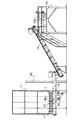
従来、被搬出物の定量搬出装置があった(たとえば特許文献1参照)。図4はその定量搬出装置の要部の平面図、図5は同じく要部の側面図であって、建屋10の外部には貯槽11が設置され、この貯槽11の底部には定量送りスクリューコンベヤー12が並設されている。一方、建屋10の外部から内部にかけて集荷用コンベヤー13が設置され、建屋10の内部には傾斜用コンベヤー14およびバドル型撹拌コンベヤー15aを含むプレス本体15などが設置されている。
【0003】
前記貯槽11の底部には複数本たとえば9本のスクリューコンベヤー12a〜12iを並設した、それぞれのスクリューコンベヤー12a〜12iの搬出方向を交互に反対向きになる(図4の矢印参照)ようにするものである。したがって、スクリューコンベヤーが奇数本の場合に両側部のスクリューコンベヤー12a,12iの搬出方向は同一となり、さらに一つ置きのスクリューコンベヤー12c,12e,12gの搬出方向も同一となる。すなわち、この実施の形態では搬出方向のスクリューコンベヤーは5本、これと逆方向のスクリューコンベヤーは4本が互いに隣接させて配設してあり、従って、総体的に搬出方向の送り能力を大きくしてある。そして、スクリューコンベヤーの搬出方向終端部に共通の集荷用スクリューコンベヤー13を配設している。
【0004】
前記各スクリューコンベヤー12a〜12iの回転は、それぞれの端部に設けた歯車17に互いに噛み合わせ、中央の歯車17の回転軸に取り付けたスプロケット18aとモーター19の回転軸に取り付けたスプロケット18bとをチェーン20にて連結することにより行っている。
【0005】
【特許文献1】
特公昭56−21697号公報(第1頁、第2頁、第2図、第3図)
【0006】
【発明が解決しようとする課題】
前記のような従来の定量搬出装置においては、貯槽11に被搬出物を一気に投入しても、その被搬出物はスクリューコンベヤーの搬出方向終端部に一気に搬出されないで、搬出方向の5本のスクリューコンベヤーによる被搬出物の排出能力が、これと逆方向の4本のスクリューコンベヤーの能力より勝っているので、被搬出物は定量ずつ貯槽11から排出される。しかし、スクリューコンベヤーが多数必要で、この多数のスクリューコンベヤーの回転駆動機構も比較的に複雑で製造コストおよび輸送コストも高くなるといった問題があった。
本発明は、スクリューコンベヤーが1本または2本でよく、構造が簡単で製造コストおよび輸送コストも安くなる定量搬出装置を提供することを目的としたものである。また、極寒冷地などにおいて、生ごみ袋が凍結している場合においては、この凍結した生ごみ袋に高温の蒸気を吹き付けて解凍するようにした定量搬出装置を提供することを目的としたものである。
【0007】
【課題を解決するための手段】
前記目的を達成するために、請求項1に係る発明は、下方部に行くに従って狭く形成したホッパー1の下方部位置1aに少なくとも一本のスクリューコンベヤー2を設け、このスクリューコンベヤー2の上方位置に被搬出物を撹拌しながら中央部に寄せて下方に送り込むための撹拌下方送込部材3,3′を所定間隔を置いて対向して配設したことを特徴とする定量搬出装置としたものである。
【0008】
また、請求項2に係る発明は、前記撹拌下方送込部材3,3′の近傍のホッパー1の壁面1bや傾斜面1b′に高温蒸気噴出口1cを複数設けたことを特徴とする請求項1に記載の定量搬出装置としたものである。
【0009】
請求項1に係る発明のような定量搬出装置としたことにより、スクリューコンベヤーが少なくてよく、構造が簡単で製造コストおよび輸送コストも安くなる。
【0010】
また、請求項2に係る発明のような定量搬出装置としたことにより、極寒冷地などにおいて、生ごみ袋が凍結している場合には、前記高温蒸気噴出口から高温蒸気を凍結した生ごみ袋に吹き付けることにより、その凍結を解凍することができる。
【0011】
【発明の実施の形態】
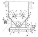
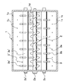
以下、本発明の定量搬出装置の実施の形態について図面を参照して詳細に説明する。図1は本発明に係る定量搬出装置を一方から見た側断面図、図2は同じく平面面で、図1で示した後述するスクリューコンベヤーおよび撹拌下方送込部材の回転駆動機構の図示を省略してある。
【0012】
請求項1に係る発明は、下方部に行くに従って狭く形成したホッパー1の下方部位置1aに少なくとも一本のスクリューコンベヤー2を設け、このスクリューコンベヤー2の上方位置に被搬出物を撹拌しながら中央部に寄せて下方に送り込むための撹拌下方送込部材3,3′を所定間隔を置いて対向して配設した定量搬出装置としたものである。
【0013】
前記撹拌下方送込部材3,3′は、軽量化を図るため所望の強度を有する筒軸などの回転軸3a,3a′の外周に放射状の湾曲棒または湾曲刃3b,3b′を複数本たとえば図に示す実施の形態のように3本設けるとともに、この3本の湾曲棒または湾曲刃3b,3b′の組み合わせを図2に示すように回転軸3a,3a′に沿って複数箇所に設けている。また、図1に示すように左側の撹拌下方送込部材3は時計回り方向に、右側の撹拌下方送込部材3′は反時計回り方向に回転するようにして、被搬出物を撹拌しながら中央部に寄せて下方に送り込むようにしている。
【0014】
前記スクリューコンベヤー2の回転駆動機構は、電動機5の回転軸に取り付けたスプロケット5aに掛けたチェーン6が前記スクリューコンベヤー2の回転軸2aに取り付けたスプロケット2bに掛けて構成されている。また、前記撹拌下方送込部材3,3′の回転駆動軸3c,3c′に、この実施の形態においてはそれぞれ電動機7,7′が連結されており、これらの電動機7,7′は撹拌下方送込部材3,3′を図1の矢印で示す方向に回転駆動し、または電気回路の切り換により図1の矢印と反対方向に回転駆動し、または撹拌下方送込部材3,3′が回転停止するようになっている。
【0015】
また、図示しないが、噛合された一方の歯車の回転軸を一個の電動機で回転駆動し、この一方の回転軸に取り付けたスプロケットと一方の撹拌下方送込部材の回転軸に取り付けたスプロケットとの間にチェーンを掛け、また、他方の歯車の回転軸に取り付けたスプロケットと他方の撹拌下方送込部材の回転軸に取り付けたスプロケットとの間にチェーンを掛けた構成にすることもできる。
【0016】
前記スクリューコンベヤー2の被搬出物の搬出側のホッパー1の底面に排出口1d(図2参照)が穿設され、この排出口1dの下方位置に次段のスクリューコンベヤー8が配設され、このスクリューコンベヤー8の排出口8aから被搬出物が排出されるようになっている。なお、前記スクリューコンベヤー8の回転軸8bに取り付けたスプロケット8cと電動機9の回転軸に取り付けたスプロケット9aとの間にチェーン6′が掛けられている。
【0017】
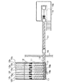
また、前記ホッパー1はその下方部が傾斜面をもって狭くなっており、その狭くなったホッパー1の下方部位置1aに、スクリューコンベヤー2が一本設けられているが、図3に示すように、スクリューコンベヤー2,2′がそれぞれ対向して配設されていてもよい。
【0018】
以上説明したように構成された定量搬出装置のホッパー1にたとえば生ごみ袋を投入すると、その生ごみ袋は一度にスクリューコンベヤー2まで到達しないで、先ずホッパー1の傾斜面1b′に当たり、さらに、撹拌下方送込部材3,3′で撹拌されて互いに中央部に寄せられて、真上からスクリューコンベヤー2に投下されてれ定量搬出される。
【0019】
請求項2に係る発明の定量搬出装置は、前記撹拌下方送込部材3,3′の近傍のホッパー1の壁面1bや傾斜面1b′に高温蒸気噴出口1cを複数設けて構成している。
極寒冷地などにおいて、生ごみ袋が凍結している場合においては、撹拌下方送込部材3,3′の湾曲棒または湾曲刃3b,3b′によって凍結した生ごみ袋が破かれず、スクリューコンベヤー2に投下された生ごみ袋が搬出されない恐れがあるが、前記のような高温蒸気噴出口1cを複数設けたことにより、生ごみ袋の凍結が高温蒸気で解凍されるので、前記のような恐れはなくなる。なお、前記高温蒸気の噴出は撹拌下方送込部材3,3′の回転中において行ってもよく、また、撹拌下方送込部材3,3′の回転停止中に行ってもよい。
【0020】
【発明の効果】
本発明の請求項1に係る発明は、前記のように、下方部に行くに従って狭く形成したホッパーの下方部位置に少なくとも一本のスクリューコンベヤーを設け、このスクリューコンベヤーの上方位置に被搬出物を撹拌しながら中央部に寄せて下方に送り込むための撹拌下方送込部材を所定間隔を置いて対向して配設した定量搬出装置としたので、スクリューコンベヤーは一本ないし二本の少ないものでよく、従って、構造が簡単で製造コストおよび輸送コストが安くなる利点がある。
【0021】
また、請求項2に係る発明は、前記のように、前記撹拌下方送込部材の近傍のホッパーの壁面や傾斜面に高温蒸気噴出口を複数設けたことを特徴とする請求項1に記載の定量搬出装置としたので、極寒冷地などにおいて、生ごみ袋が凍結している場合においては、撹拌下方送込部材によって袋が破かれず、スクリューコンベヤーに投下された生ごみ袋が搬出されない恐れがあるが、前記のような高温蒸気噴出口を複数設けたことにより、生ごみ袋の凍結が高温蒸気で解凍されるので、前記のような恐れはなくなる。
【図面の簡単な説明】
【図1】本発明に係る定量搬出装置を一方から見た側断面図である。
【図2】本発明に係る定量搬出装置の平面面である。
【図3】本発明に係る定量搬出装置を構成するスクリューコンベヤーをホッパーの下方部位置に2本設けた実施の形態を示す図である。
【図4】従来の定量搬出装置の要部の平面図である。
【図5】従来の定量搬出装置の要部の要部の側面図である。
【符号の説明】
1 ホッパー
1a 下方部位置
1b 壁面
1b′ 傾斜面
1c 高温蒸気噴出口
1d 排出口
2 スクリューコンベヤー
2′ スクリューコンベヤー
2a 回転軸
2b スプロケット
3 撹拌下方送込部材
3′ 撹拌下方送込部材
3a 回転軸
3a′ 回転軸
3b 湾曲棒または湾曲刃
3b′ 湾曲棒または湾曲刃
3c 回転軸
3c′ 回転軸
3d スプロケット
3d′ スプロケット
5 電動機
5a スプロケット
6 チェーン
6′ チェーン
7 電動機
7′ 電動機
8 スクリューコンベヤー
8a 排出口
8b 回転軸
8c スプロケット
9 電動機
9a 回転軸
9b スプロケット[0001]
TECHNICAL FIELD OF THE INVENTION
TECHNICAL FIELD The present invention relates to a constant-rate delivery device for carrying out a fixed amount of an object to be carried out, such as a garbage bag, put into the hopper out of the hopper by a screw conveyor arranged at a lower position of the hopper.
[0002]
[Prior art]
2. Description of the Related Art Conventionally, there has been an apparatus for quantitatively carrying out unloading (see, for example, Patent Document 1). FIG. 4 is a plan view of a main part of the fixed-quantity carry-out device, and FIG. 5 is a side view of the same main part. A storage tank 11 is installed outside the building 10, and a fixed-rate screw conveyor is provided at the bottom of the storage tank 11. 12 are juxtaposed. On the other hand, a conveyer 13 for collecting cargo is installed from the outside to the inside of the building 10, and a press body 15 including an inclined conveyor 14 and a paddle type stirring conveyor 15 a is installed inside the building 10.
[0003]
At the bottom of the storage tank 11, a plurality of, for example, nine screw conveyors 12a to 12i are juxtaposed, and the unloading directions of the screw conveyors 12a to 12i are alternately opposite (see arrows in FIG. 4). Things. Therefore, when the number of screw conveyors is odd, the carrying-out direction of the screw conveyors 12a and 12i on both sides is the same, and the carrying-out direction of every other screw conveyors 12c, 12e and 12g is also the same. That is, in this embodiment, five screw conveyors in the unloading direction and four screw conveyors in the opposite direction are arranged adjacent to each other, and therefore, the feeding capacity in the unloading direction is generally increased. It is. A common screw conveyor 13 for collection is provided at the end of the screw conveyor in the carrying-out direction.
[0004]
The rotation of each of the screw conveyors 12a to 12i is performed by engaging a gear 17 provided at each end with a sprocket 18a attached to a rotation shaft of a central gear 17 and a sprocket 18b attached to a rotation shaft of a motor 19. It is performed by connecting with a chain 20.
[0005]
[Patent Document 1]
JP-B-56-21697 (Page 1, Page 2, Figure 2, Figure 3)
[0006]
[Problems to be solved by the invention]
In the above-mentioned conventional fixed-quantity unloading device, even if the unloading material is thrown into the storage tank 11 at a stretch, the unloading material is not unloaded at the end of the screw conveyor in the unloading direction. Since the discharge capacity of the conveyed material by the conveyor is superior to the capacity of the four screw conveyors in the opposite direction, the conveyed material is discharged from the storage tank 11 by a fixed amount. However, there is a problem that a large number of screw conveyors are required, and the rotational drive mechanism of the large number of screw conveyors is relatively complicated, and the production cost and the transportation cost are increased.
SUMMARY OF THE INVENTION An object of the present invention is to provide a fixed-quantity carry-out device that requires only one or two screw conveyors, has a simple structure, and has low manufacturing and transportation costs. In addition, in an extremely cold region, when the garbage bag is frozen, it is an object to provide a fixed-quantity carry-out device in which high-temperature steam is blown onto the frozen garbage bag to defrost the bag. It is.
[0007]
[Means for Solving the Problems]
In order to achieve the above object, the invention according to claim 1 is provided with at least one screw conveyor 2 at a lower part position 1a of a hopper 1 formed narrower toward a lower part, and at a position above the screw conveyor 2 A fixed-quantity unloading device characterized in that agitated lower sending members 3, 3 'for bringing the unloading material toward the center while stirring and sending the unloaded material downward are arranged at predetermined intervals to face each other. is there.
[0008]
The invention according to claim 2 is characterized in that a plurality of high-temperature steam outlets 1c are provided on the wall surface 1b or the inclined surface 1b 'of the hopper 1 near the stirring lower feeding members 3, 3'. 1 is a quantitative discharge device.
[0009]
By adopting the fixed-quantity carry-out device as in the first aspect of the present invention, the number of screw conveyors may be small, the structure is simple, and the manufacturing cost and the transportation cost are reduced.
[0010]
In addition, by using the quantitative discharge device as in the invention according to claim 2, when the garbage bag is frozen in an extremely cold region or the like, the garbage in which the high-temperature steam is frozen from the high-temperature steam jet port is frozen. By spraying the bag, the freeze can be thawed.
[0011]
BEST MODE FOR CARRYING OUT THE INVENTION
Hereinafter, an embodiment of a fixed quantity carrying-out device of the present invention will be described in detail with reference to the drawings. FIG. 1 is a side sectional view of a fixed-quantity carrying-out device according to the present invention as viewed from one side, and FIG. 2 is a plan view of the same. I have.
[0012]
In the invention according to claim 1, at least one screw conveyor 2 is provided at a lower part position 1a of a hopper 1 which is formed narrower toward a lower part, and the conveyed material is stirred above the screw conveyor 2 while being stirred. In this case, the stirring lower sending members 3 and 3 'for sending them downward toward the section are provided as a fixed-quantity carry-out device which is arranged to face each other at a predetermined interval.
[0013]
The stirring lower feeding members 3 and 3 'include a plurality of radially curved rods or curved blades 3b and 3b' on the outer periphery of rotary shafts 3a and 3a 'such as cylindrical shafts having a desired strength in order to reduce the weight. As shown in the embodiment shown in FIG. 3, three curved bars or curved blades 3b, 3b 'are provided at a plurality of positions along the rotating shafts 3a, 3a' as shown in FIG. I have. Also, as shown in FIG. 1, the left stirring lower sending member 3 rotates clockwise, and the right stirring lower sending member 3 'rotates counterclockwise. It is sent toward the center and sent downward.
[0014]
The rotary drive mechanism of the screw conveyor 2 is configured such that a chain 6 hung on a sprocket 5a attached to the rotating shaft of the electric motor 5 is hung on a sprocket 2b attached to the rotating shaft 2a of the screw conveyor 2. In this embodiment, electric motors 7, 7 'are connected to the rotary drive shafts 3c, 3c' of the stirring lower feed members 3, 3 ', respectively. The feeding members 3, 3 'are driven to rotate in the direction shown by the arrow in FIG. 1, or are rotated in the direction opposite to the arrow in FIG. It is designed to stop rotating.
[0015]
Although not shown, the rotating shaft of one of the meshed gears is driven to rotate by one electric motor, and the sprocket attached to the one rotating shaft and the sprocket attached to the rotating shaft of the one stirring lower sending member are rotated. It is also possible to adopt a configuration in which a chain is interposed between the sprocket mounted on the rotating shaft of the other gear and the sprocket mounted on the rotating shaft of the other stirring lower feeding member.
[0016]
A discharge port 1d (see FIG. 2) is formed in the bottom surface of the hopper 1 on the unloading side of the conveyed material of the screw conveyor 2, and a screw conveyor 8 of the next stage is disposed below the discharge port 1d. The conveyed material is discharged from the discharge port 8a of the screw conveyor 8. A chain 6 'is hung between a sprocket 8c attached to the rotating shaft 8b of the screw conveyor 8 and a sprocket 9a attached to the rotating shaft of the electric motor 9.
[0017]
The lower part of the hopper 1 is narrowed with an inclined surface, and one screw conveyor 2 is provided at a lower part position 1a of the narrowed hopper 1, as shown in FIG. The screw conveyors 2 and 2 'may be arranged facing each other.
[0018]
When, for example, a garbage bag is put into the hopper 1 of the quantitative discharge device configured as described above, the garbage bag does not reach the screw conveyor 2 at a time, but first hits the inclined surface 1b 'of the hopper 1, and further, The mixture is agitated by the agitating lower feeding members 3 and 3 ′, brought to the center of each other, dropped onto the screw conveyor 2 from directly above, and is discharged at a constant rate.
[0019]
The fixed quantity discharge device according to the second aspect of the present invention comprises a plurality of high-temperature steam injection ports 1c provided on the wall surface 1b and the inclined surface 1b 'of the hopper 1 near the stirring lower sending members 3, 3'.
When the garbage bag is frozen in an extremely cold region or the like, the frozen garbage bag is not broken by the curved rods or curved blades 3b, 3b 'of the stirring lower feeding members 3, 3', and the screw conveyor is not broken. There is a possibility that the garbage bag dropped in 2 may not be carried out. However, by providing a plurality of high-temperature steam jet ports 1c as described above, the garbage bag is frozen by the high-temperature steam and thawed. Fear is gone. The high-temperature steam may be ejected during rotation of the lower stirring member 3, 3 'or during rotation of the lower stirring member 3, 3'.
[0020]
【The invention's effect】
According to the first aspect of the present invention, as described above, at least one screw conveyor is provided at a lower portion of a hopper formed narrower toward a lower portion, and an object to be conveyed is located at a position above the screw conveyor. Since the fixed lower discharge member is arranged opposite to the stirring lower feeding member at a predetermined interval for feeding toward the center portion while stirring and sending it downward, the number of screw conveyors may be as small as one or two. Therefore, there is an advantage that the structure is simple and the manufacturing cost and the transportation cost are low.
[0021]
The invention according to claim 2 is characterized in that, as described above, a plurality of high-temperature steam injection ports are provided on a wall surface or an inclined surface of the hopper near the stirring lower feeding member. Because the fixed-quantity carry-out device is used, if the garbage bag is frozen in an extremely cold region, the garbage bag dropped on the screw conveyor may not be carried out due to the bag not being broken by the stirring lower sending member. However, by providing a plurality of high-temperature steam jet ports as described above, the garbage bag is thawed by the high-temperature steam, so that the above-mentioned fear is eliminated.
[Brief description of the drawings]
FIG. 1 is a side sectional view of a fixed-quantity carrying-out device according to the present invention as viewed from one side.
FIG. 2 is a plan view of the fixed-quantity carry-out device according to the present invention.
FIG. 3 is a diagram showing an embodiment in which two screw conveyors constituting the fixed-quantity carry-out device according to the present invention are provided at a lower position of a hopper.
FIG. 4 is a plan view of a main part of a conventional fixed-quantity carry-out device.
FIG. 5 is a side view of a main part of a main part of a conventional fixed-quantity carry-out device.
[Explanation of symbols]
DESCRIPTION OF SYMBOLS 1 Hopper 1a Lower part position 1b Wall surface 1b 'Inclined surface 1c Hot steam outlet 1d Discharge port 2 Screw conveyor 2' Screw conveyor 2a Rotary shaft 2b Sprocket 3 Stirring lower sending member 3 'Stirring lower sending member 3a Rotating shaft 3a' Rotating shaft 3b Curved bar or curved blade 3b 'Curved bar or curved blade 3c Rotating shaft 3c' Rotating shaft 3d Sprocket 3d 'Sprocket 5 Motor 5a Sprocket 6 Chain 6' Chain 7 Motor 7 'Motor 8 Screw conveyor 8a Discharge port 8b Rotating shaft 8c sprocket 9 electric motor 9a rotating shaft 9b sprocket