【0001】
【発明の属する技術分野】
この発明はトイレや洗面所などの床面に設置される水封防臭式ワントラップ型排水機構における、悪臭の逆流や虫の潜入など、特に環境的に不潔になりやすい汚染箇所の環境向上を目的とし、水封防臭式ワントラップの水が減少し水封防臭、防虫機能が無くなる前に液を自動的に供給する補充液タンク型ワントラップに関するものである。
【0002】
【従来の技術】
従来、トイレや洗面所などの床面に設置される水封防臭式ワントラップ型排水機構は、環境的や作用的や管理的に問題が発生した場合の補助的安全保持機構などは施されておらず、特に防臭や防虫機能の安全に関する補助機構的技術は開発されていなかった。
【0003】
【発明が解決しようとする課題】
従来のトイレや洗面所の水封防臭式ワントラップ型排水機構は補助的安全保持機構が施されていないため次の課題があった。
(イ)ワントラップ排水機構は水封防臭方式であるため、水が無くなった場合には防臭機能や防虫機能を果たさなくなり、特にトラップ皿の水溜部は上部が開口されており蒸発による乾燥を促進させるし、また水溜まり域のトラップ皿は構造的にもゴミなどの汚れが溜まりやすい部分であり、床面のゴミなどの異物が集積蓄積され溜まり水量を減少させており、乾燥作用により拍車をかけることになり水封防臭式の最大の問題であった。
(ロ)水封式ワントラップ排水口の機構や作用などを理解する人も少なく、水の補給を滞るなどの管理的問題も多かった。
【0004】
【問題を解決するための手段】
いまその課題を解決するための構成を図面により説明すれば、
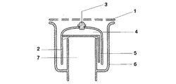
(イ)トイレや洗面所などの床面などに設置される水封防臭式ワントラップの防臭ワン2の上部を液体入れタンク構造として、その液体入れタンク4からトラップ皿6下部へ液体を供給する液体供給路5を有して、水封用の水が少なくなったら液体入れタンク4の液体供給路5からトラップ皿6へ自動的に液を補充する基本システムである。
(ロ)水封防臭式ワントラップ型排水機構において、防臭ワン2上部の液体入れタンク4から液体をトラップ皿6へ供給する液体供給路5を有し、液体供給路5下端の液体排出口位置は防臭ワン2の下端より若干上位置として、トラップ皿6の水が少なくなり水封機能が無くなる前に液体を供給可能とする位置とするし、液体入れタンク4の天井部には液体注入用の注入口とその密閉蓋3を有した構成である。
(ハ)液体供給路5の内径は、液体排出口がトラップ皿6の水中に位置する場合にはその水圧で液体入れタンク4内の液が排出されず保持できるし、水量が減少して液体排出口が水中より脱した場合には空気圧では保持できずトラップ皿6に夜を排出して水封作用を可能とする寸法構造である。
(ニ)液体供給路5の厚みはトラップ皿6と防臭ワン2の間隔を配慮した薄型寸法とする。
(ホ)補充液は水でもよいが、できれば芳香液や消臭液などとする。
【0005】
【作用】
次に本発明の作用を述べると、
(イ)トイレなどの床面の清掃などで水洗いした水やゴミなどの異物は目皿1を通って防臭ワン2よりトラップ皿6に溜まり、溢れる水は排出口7から排水される作用であるため、水封用の水はトラップ皿6の下部に溜まり防臭や防虫の作用をなすものである。
(ロ)トラップ皿6の水が気化作用などにより減少し液体供給路5下端の排出口が水中を脱すると液体の保持力が失われて液体入れタンク4の液体は液体供給路5下端の排出口から排出してトラップ皿6の水を補充し水封機能を保持する作用である。
(ハ)液体入れタンク4の液体の補充は定期的に行うことも可能であり、密閉蓋3を開けて注入口から液を補充する作用であるし、液体入れタンク4に液を入れ密閉蓋3を閉めることにより液体供給路5下端の排出口がトラップ皿6の水中にある場合は水圧により液が排出口から排出されず液体入れタンク4内に保持されるし、トラップ皿6の水が減少して排出口が水中から脱すると液体入れタンク4内の液が液体供給路5を通って下端の排出口からトラップ皿6へ排出されて液を自動的に補充し水封機能を果たす作用である。
(ニ)液体入れタンク4の液体は芳香液や消臭液などとして、芳香液を入れれば液の補充時点で香を漂わせて快適な環境を提供できますし、また水封用の水が減っていることを知らせる警報的作用もなすものである。
【0006】
【発明の実施の形態】
具体実施例を述べる、
(イ)液体入れタンク4に接続する液体供給路5を管やホースとする。
(ロ)目皿1と防臭ワン2がビス止め構造の場合にビス自体を密閉蓋3と共有する構成とする。
【0007】
【発明の効果】
水封用液の自動補充による防臭、防虫作用により、より安全で快適な環境を保持できます。
具体的効果を列記すれば、
(イ)従来のワントラップ排水機構は構造的にも乾燥しやすいし、ゴミなどの異物が溜まりやすい構造であるため水封式防臭、防虫機構としては未だ不十分であったが、補充液タンク型ワントラップにより水到用の液を自動的に補充する構成であり水封式防臭、防虫効果を高めて、環境の安全性の向上に寄与します。
(ロ)液体入れタンク4の液体を芳香消臭液などとすれば液の補充時点で香を漂わせて快適な環境を提供できますし、またその香により水封用の水が減っていることを知らせる警報的効果もなすものであります。
【0008】
トイレや洗面所などの環境的に汚染されやすい場所において、従来の構造的、管理的問題などを解決し、防臭や防虫作用の安全機構を確立できるため、汚染しやすい場所の生活環境を向上させ、明るく楽しい社会づくりに大きく貢献するものであります。
【図面の簡単な説明】
【図1】本発明の一部断面図を含む斜視図
【図2】本発明の中央断面図
【符号の説明】
1は目皿 2は防臭ワン
3は密閉蓋 4は液体入れタンク
5は液体供給路 6はトラップ皿 7は排水口[0001]
TECHNICAL FIELD OF THE INVENTION
The present invention aims to improve the environment of contaminated places that are likely to be environmentally unclean, such as the backflow of odors and the infiltration of insects, in a water-seal and deodorant type one-trap type drainage mechanism installed on the floor such as a toilet or a washroom. The present invention relates to a replenisher tank type one trap which automatically supplies a liquid before the water in the water seal deodorant type one trap decreases and the water seal deodorant and insect repellent functions are lost.
[0002]
[Prior art]
Conventionally, the water-seal and deodorant one-trap type drainage mechanism installed on the floor such as a toilet or a washroom is provided with an auxiliary safety maintenance mechanism when an environmental, operative or management problem occurs. No auxiliary mechanism technology has been developed, especially for the safety of deodorant and insect repellent functions.
[0003]
[Problems to be solved by the invention]
The conventional one-trap type water-seal deodorizing system for toilets and washrooms has the following problems because an auxiliary safety holding mechanism is not provided.
(1) Since the one-trap drainage mechanism is a water-seal and deodorant system, when the water runs out, it does not function as a deodorant or insect repellent. In particular, the trap reservoir has an open top to promote drying by evaporation. In addition, the trap plate in the water pool area is a part where dirt such as dust easily accumulates structurally, and foreign substances such as dust on the floor surface are accumulated and reduced, and the amount of accumulated water is reduced. This was the biggest problem with the water seal deodorant system.
(B) Few people understood the mechanism and operation of the water-sealed one-trap drain, and there were many management problems such as delaying water supply.
[0004]
[Means to solve the problem]
Now, a configuration for solving the problem will be described with reference to the drawings.
(A) The upper part of the deodorant one 2 of the water-seal deodorant type one trap installed on the floor surface of a toilet or a washroom has a liquid storage tank structure, and supplies the liquid from the liquid storage tank 4 to the lower part of the trap plate 6. This is a basic system having a liquid supply path 5 and automatically replenishing the liquid from the liquid supply path 5 of the liquid tank 4 to the trap plate 6 when the amount of water for water sealing is low.
(B) In a water-seal and deodorant type one trap type drain mechanism, a liquid supply path 5 for supplying liquid to a trap plate 6 from a liquid tank 4 above the deodorant one 2 is provided, and a liquid outlet position at a lower end of the liquid supply path 5 is provided. Is located slightly above the lower end of the deodorant one 2 so that liquid can be supplied before the water in the trap plate 6 becomes low and the water sealing function is lost. And a sealing lid 3 for the injection port.
(C) When the liquid outlet is located in the water of the trap plate 6, the inner diameter of the liquid supply passage 5 can maintain the liquid in the liquid tank 4 without being discharged by the water pressure, and the amount of liquid decreases as the amount of water decreases. When the outlet is removed from the water, it cannot be held by air pressure, and the nighttime is discharged to the trap plate 6 to enable a water sealing function.
(D) The thickness of the liquid supply path 5 is thin so as to allow for the space between the trap plate 6 and the deodorant one 2.
(E) The replenisher may be water, but if possible, an aromatic liquid or a deodorant liquid.
[0005]
[Action]
Next, the operation of the present invention will be described.
(A) Water and trash, etc., which have been washed with water for cleaning the floor of a toilet or the like, pass through the eye plate 1 and collect in the trap plate 6 from the deodorant one 2, and overflow water is drained from the outlet 7. Therefore, the water for water sealing is accumulated at the lower part of the trap plate 6 and acts as an odor control and insect repellent.
(B) When the water in the trap plate 6 decreases due to vaporization and the like, and the discharge port at the lower end of the liquid supply path 5 comes out of the water, the holding power of the liquid is lost and the liquid in the liquid storage tank 4 is discharged at the lower end of the liquid supply path 5. The function is to discharge water from the outlet to replenish the water of the trap plate 6 and maintain the water sealing function.
(C) It is also possible to periodically replenish the liquid in the liquid tank 4 with the function of opening the airtight lid 3 and replenishing the liquid from the injection port. When the outlet of the lower end of the liquid supply path 5 is in the water of the trap plate 6 by closing the liquid supply passage 3, the liquid is not discharged from the outlet by the water pressure, but is held in the liquid storage tank 4, and the water of the trap plate 6 is discharged. When the outlet decreases from the water and the outlet exits from the water, the liquid in the liquid storage tank 4 passes through the liquid supply passage 5 and is discharged from the lower outlet to the trap plate 6 to automatically replenish the liquid and perform the water sealing function. It is.
(D) The liquid in the liquid tank 4 is used as an aromatic liquid or a deodorant liquid. If an aromatic liquid is added, a fragrance can be provided at the time of replenishing the liquid and a comfortable environment can be provided. It also acts as an alarm to signal that it is running low.
[0006]
BEST MODE FOR CARRYING OUT THE INVENTION
Describe specific examples,
(A) The liquid supply path 5 connected to the liquid storage tank 4 is a pipe or a hose.
(B) When the eye plate 1 and the deodorant one 2 have a screw structure, the screws themselves are shared with the sealing lid 3.
[0007]
【The invention's effect】
Deodorant and insect repellent action by automatic replenishment of liquid for water seal, can maintain more safe and comfortable environment.
If you list the specific effects,
(A) The conventional one-trap drainage mechanism is structurally easy to dry and has a structure that easily accumulates foreign matter such as dust, so it was still insufficient as a water-seal type deodorant and insect-proof mechanism, but a replenisher tank It is configured to automatically replenish the liquid for water arrival with a one-type trap, which enhances the water-seal type deodorant and insect repellent effects and contributes to the improvement of environmental safety.
(B) If the liquid in the liquid tank 4 is an aroma deodorizing liquid or the like, a fragrance can be drifted when the liquid is replenished to provide a comfortable environment, and the scent reduces the amount of water for water sealing. It also has a warning effect to inform you.
[0008]
In places that are easily polluted by the environment, such as toilets and washrooms, conventional structural and management problems can be solved, and a safety mechanism for odor control and insect control can be established. It will greatly contribute to the creation of a bright and enjoyable society.
[Brief description of the drawings]
FIG. 1 is a perspective view including a partial sectional view of the present invention. FIG. 2 is a central sectional view of the present invention.
1 is an eye plate 2 is a deodorant one 3 is a closed lid 4 is a liquid tank 5 is a liquid supply channel 6 is a trap plate 7 is a drain port