JP2004134018A - Information recording method and reproduction method - Google Patents
Information recording method and reproduction method Download PDFInfo
- Publication number
- JP2004134018A JP2004134018A JP2002298229A JP2002298229A JP2004134018A JP 2004134018 A JP2004134018 A JP 2004134018A JP 2002298229 A JP2002298229 A JP 2002298229A JP 2002298229 A JP2002298229 A JP 2002298229A JP 2004134018 A JP2004134018 A JP 2004134018A
- Authority
- JP
- Japan
- Prior art keywords
- information
- recording
- state
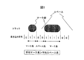
- code
- mark
- Prior art date
- Legal status (The legal status is an assumption and is not a legal conclusion. Google has not performed a legal analysis and makes no representation as to the accuracy of the status listed.)
- Pending
Links
Images







Classifications
-
- G—PHYSICS
- G11—INFORMATION STORAGE
- G11B—INFORMATION STORAGE BASED ON RELATIVE MOVEMENT BETWEEN RECORD CARRIER AND TRANSDUCER
- G11B20/00—Signal processing not specific to the method of recording or reproducing; Circuits therefor
- G11B20/10—Digital recording or reproducing
- G11B20/10009—Improvement or modification of read or write signals
-
- G—PHYSICS
- G11—INFORMATION STORAGE
- G11B—INFORMATION STORAGE BASED ON RELATIVE MOVEMENT BETWEEN RECORD CARRIER AND TRANSDUCER
- G11B20/00—Signal processing not specific to the method of recording or reproducing; Circuits therefor
- G11B20/10—Digital recording or reproducing
- G11B20/14—Digital recording or reproducing using self-clocking codes
- G11B20/1403—Digital recording or reproducing using self-clocking codes characterised by the use of two levels
- G11B20/1423—Code representation depending on subsequent bits, e.g. delay modulation, double density code, Miller code
- G11B20/1426—Code representation depending on subsequent bits, e.g. delay modulation, double density code, Miller code conversion to or from block codes or representations thereof
-
- H—ELECTRICITY
- H03—ELECTRONIC CIRCUITRY
- H03M—CODING; DECODING; CODE CONVERSION IN GENERAL
- H03M5/00—Conversion of the form of the representation of individual digits
- H03M5/02—Conversion to or from representation by pulses
- H03M5/04—Conversion to or from representation by pulses the pulses having two levels
- H03M5/14—Code representation, e.g. transition, for a given bit cell depending on the information in one or more adjacent bit cells, e.g. delay modulation code, double density code
- H03M5/145—Conversion to or from block codes or representations thereof
-
- G—PHYSICS
- G11—INFORMATION STORAGE
- G11B—INFORMATION STORAGE BASED ON RELATIVE MOVEMENT BETWEEN RECORD CARRIER AND TRANSDUCER
- G11B20/00—Signal processing not specific to the method of recording or reproducing; Circuits therefor
- G11B20/10—Digital recording or reproducing
- G11B20/12—Formatting, e.g. arrangement of data block or words on the record carriers
Landscapes
- Engineering & Computer Science (AREA)
- Signal Processing (AREA)
- Theoretical Computer Science (AREA)
- Signal Processing For Digital Recording And Reproducing (AREA)
- Optical Recording Or Reproduction (AREA)
Abstract
Description
【0001】
【発明の属する技術分野】
本発明は、光ディスクに情報を記録する方法、記録された情報を再生する方法に関する。
【0002】
【従来の技術】
CDやDVDなどの光ディスクシステムにおいては、情報の記録にマークエッジ記録方式が用いられている。これは、記録マークとスペース(マーク間部)の境界(エッジ)に2値データ”1”を割り当て、その他の部分に”0”を割り当てる方式である。その際、光ディスクの光スポットの分解能の制限を超えた高密度(高効率)記録を行うために、“1”と“1”の間の連続する“0”の個数に制限を加えたラン長制限符号(RLL符号)が用いられる。これにより、最短マークや最短スペースの長さを光の分解能限界より長く保ったまま高密度記録を行うことができる。たとえば、CD(Compact Disk)に使用されているEFM符号や、DVDに使用されているEFMPlus符号(または8−16符号と呼ばれる)はマーク/スペース長の最小値が3T(Tはチャネルクロック周期)に制限されているラン長制限符号である。これらの符号については、例えば、米国特許第5696505号公報に開示されている。
【0003】
EFM符号、EFMPlus(8−16符号)は(d、k)RLL符号でd=2、k=10である。ここでd=2、k=10というのは、ラン長制限符号上での“1”と“1”の間に入る“0”の数の最小値と最大値である。実際の記録はエッジでなくマークを記録するので、NRZI変換を行った結果の“1”/“0”をマーク/スペースに対応させて行う。NRZI変換では、ラン長制限符号が“1”のとき、“1”→“0”、“0”→“1”のように符号の反転を行い、ラン長制限符号が“0”のときは符号はそのままという変換を行うので、d+1が最小のマーク、スペースの長さとなる。すなわちEFM符号やEFMPlus符号において最小のマーク、スペースの長さはともに3ビットであった。
【0004】
また最短ラン長d=1の代表例としては,光磁気ディスクに採用されている1−7変調が有る。d=1であるため最短マーク/スペース長は2Tとなる。
【0005】
近年、光ディスク装置においても更なる記録密度の高密度化が要求されている。このため、光ディスク装置においてパーシャルレスポンス再尤復号方式(Partial Response Maximum Likelihood:以後PRMLと略記する)の採用が検討されるようになってきた。
【0006】
従来から、磁気ディスク装置では記録密度を向上させるために通信分野で使われている技術を応用したPRMLが用いられていた。パーシャルレスポンス(PR)は、符号間干渉(隣り合って記録されているビットに対応する再生信号同士の干渉)を積極的に利用して必要な信号帯域を圧縮しつつデータの再生を行う方法である。また、ビタビ復号方式(ML)は、いわゆる再尤系列推定方式の1種であって、再生波形のもつ符号間干渉の規則を有効に利用し、複数時刻にわたる信号振幅の情報に基いてデータ再生を行う。
【0007】
【発明が解決しようとする課題】
しかしながら、従来の光ディスクにおいては、高信頼性と低エラーレートとを両立して記録、再生することが困難であった。
【0008】
本発明の目的は,常に高信頼かつ低エラーレートで記録再生することの可能な光記録再生システムを提供することにある。
【0009】
【課題を解決するための手段】
本願発明者らは、上記従来の課題について、分析、検討した。光ディスクにおいては図6に記載のように,一般に記録マーク部とスペ−ス部では物理的態様が異なるため,信号品質そのものが,マーク部とスペース部で異なるのが常であった。例えば,試作した相変化型記録媒体においては,スペース部分が結晶(多結晶),記録部分がアモルファスと言う形態で記録されるが,アモルファス部分では,非常に均一な物理構造になっているのに対し,スペース部分では多結晶の結晶軸のばらつきや,結晶粒界での光の散乱などによって,一般にノイズが増加する傾向にある。図16は試作した相変化記録媒体の信号揺らぎ成分の分布を分析したものである。図中、位置で、マークと記載されていない箇所は、スペース領域である。図16より、スペースの部分にノイズ成分が集中していることが分かる。この例ではスペース部のノイズはマーク部に対して約6dBも高い。このため,たとえ,微細なマークを正確に形成できたとしても,スペース部分の信号揺らぎなどにより信号品質が劣化してしまい,結果として,高速・高密度記録再生が出来ないのである。また別の例として,追記型光ディスクでは色素や無機薄膜などの記録膜を用い,記録や基板の変形,材料の拡散などを利用して記録マークを形成したりするが,この場合には,高密度記録を行おうとした際に,微小な記録マークが安定に形成できないため,記録マークの信号品質が低い傾向にある。この場合も結果として高速・高密度記録再生が困難になる。
【0010】
そこで、本発明では、マークとスペースの部分のうち,記録再生信号品質が良好な側の信号成分を多くするように平均マーク長と平均スペース長の比を1:1からずらしたマーク記録符号を適用した。
【0011】
マーク長やスペース長はラン長+1チャネルビット(1T)となっているため、別の言い方をすれば、平均ラン長がマークとスペース部で異なるような符号を適用したことに相当する。即ち、RLL符号化規則を用い、記録膜に、第1の状態と、前記第1の状態とは異なる第2の状態を形成し。第1の状態と第2の状態との境界に情報を持たせるように記録する際、第1の状態を記録するときのRLL符号の平均ラン長が、第2の状態を記録するときのそれよりも短いようにした。ここで、相変化記録の場合には、第1の状態は結晶であり、第2の状態はアモルファスである。この場合,上記のように,スペース部分(結晶)のノイズが,マーク部分(アモルファス)のノイズとくらべて大きいため,図1のように,平均スペース長が,平均マーク長よりも短いようにして,情報を記録する。
【0012】
上記平均マーク長と平均スペース長の比を1:1からずらす際には、マークが極端に多い部分と少ない部分が記録トラック上に混在すると、再生信号の低周波揺らぎとなり、サーボシステムや、同期システム(PLL)に悪影響を与えるため、比が媒体の特性などによってあらかじめ定めた一定の値になるように制御するのが望ましい。このことは、マーク部とスペース部の平均ラン長で議論する際にも同様である。
【0013】
上記比を一定の目標値に制御するためには、マークの部分を−1、スペースの部分を1としたときの累積値DSV(Digital Sum Value)を、一定期間ごとに所定の値を加えた値に近づくように制御するのが装置構成上簡便である。
【0014】
このような符号化を行うことにより、符号に含まれる低周波成分を低く抑えることができる。ただし,マーク部とスペース部の割合が異なるために,DC成分そのものはゼロにはならず,所定の値となる。
【0015】
一方、再生過程では,記録媒体からピックアップヘッドを用いて再生信号を得る過程,再生信号に周波数特性補正を行う波形等化過程,再生信号の振幅を所定の値にするゲイン制御過程,再生信号を所定の判別レベルにより,”1”,”0”を判別して,変調データビット列を得る過程,および変調データビット列をラン長制限符号規則により復号して,ディジタル情報を得る過程からなり,変調データビット列に含まれる”1”の数をN1,”0”の数をN0としたとき,比率R=N1/N0が予め定めた値になるように,判別レベルの値を適応的に制御する。
【0016】
図2はマークとスペースの比を変えることにより信号品質がどのように向上するかを示したものである。スペース部のノイズがマーク部のノイズに対して5dB高い場合と、10dB高い場合の各々について、スペース/マーク比が1:1の場合とのトータルノイズレベルの差を計算したものである。マーク/スペース両者からの信号揺らぎ(ノイズ)影響(トータルノイズ)は、次式にて表される。
【0017】
【式1】

Pmark:マーク部の割合
Pspace:スペース部の割合
Nmark:マーク部のノイズレベル
Nspace:スペース部のノイズレベル
である。
【0018】
図2よると、たとえば、スペース部のノイズレベルがマーク部よりも10dB高い系の場合、スペース割合を2割減らして0.3とすると、約2dBのノイズレベルを低減できる。
【0019】
なお、本願発明を完成させた後に、公知例調査を行った結果、特開2000−163887号が見いだされた。この公報には、マーク列に対応するビット列と、スペースに対応するビット列と、各々に対して、RLLの最小長さと最大長さを満足する範囲内で、所定大きさの量子化された値のみを有するように選択された変調データを選定して変調し、復調時に量子化条件に基づいて再生エラーを確認することが記載されている。しかし、この公報は、本願のように、平均ラン長がマークとスペース部で異なるような符号を適用するものではない。
【0020】
【発明の実施の形態】
(実施例1)
図3は、本発明の一実施例における光ディスク装置の概略構成を示すブロック図である。光ディスク装置は、以下に説明するように、コンピュータシステムの記憶装置として用いられる場合もあれば、テレビと接続されて据え置き型の画像、音声記録再生装置として用いられる場合もある。また、携帯ビデオカメラ、携帯音楽再生装置などの記録再生装置として用いられる場合もある。
【0021】
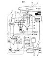
図3において、上位装置6とはパーソナルコンピュータなどのホストコンピュータやビデオ制御装置などのアプリケーション機器である。記録符号化回路51は、ホストインターフェース61を介して上位装置から受け取った記録すべきユーザデータを、あらかじめ定められた規則に従って変調し、記録媒体1に記録できるデータに変換する(この処理を符号化という)。
【0022】
レーザドライバ52は、符号化されたデータを符号化回路51から受け取り、記録再生ヘッド2中のレーザ光源25を駆動するのに好適な電圧波形に変換する。記録再生ヘッド2では、受け取った電圧波形をレーザ光源25によってレーザ光に変換する。レーザ光はコリメータレンズ24によって,平行な光ビーム22となり,対物レンズ23によって絞り込まれて形成される光のスポット21により,ディスク様媒体1上にマークを書き込む。この際,アクチュエータ31によって対物レンズ23を動かすことによって光スポットの位置を制御する。記録は一般に光スポット21の光エネルギーにより、媒体記録膜の温度が上がるのを利用して行われる。これは、書き換え型DVDなどの相変化型記録媒体、追記型CDなどの色素系記録媒体などに共通である。
【0023】
データの読み出し時には、光スポット21の部分の反射光をビームスプリッタ28によって再生系に導き、レンズ24にて絞り込んで検出器27で検出する。このとき、マーク部とスペース部の光の反射強度の差を利用して、反射光によりデータを読み出し、読み出した情報を電気情報に変換する。この電気信号は、記録再生アンプにて適度な増幅が行われた後、再生ブロック41へと送られる。
【0024】
再生ブロック41に入力された再生信号はまず信号処理回路45に送られ、波形等化やフィルタリング(帯域制限)など適当な再生信号処理が行われた後、この信号をアナログデジタル変換(サンプリング)して振幅情報(デジタル)に変換し,復調回路44へ送出する。復号回路44では、この振幅情報に基づいてビタビ(ML)復調を行い、もっとも確からしい(最尤)データ系列を生成する。
【0025】
得られたデータ列は、復号回路46において、符号化回路51と逆の符号変換が行われて(この処理を復号化という)、元のデータが復元される。この際,検出器27の出力差信号を,アドレス検出回路42でアドレス情報に変換した後,フォーマット制御回路43で,データ構造に従って生成されたタイミング信号を用いる。
光ディスク装置では、以上のような手順によってデータの記録再生が行われる。
【0026】
本実施例では、復調回路44で、PR(121)を用いる。すなわち、1ビットのマーク/スペース(1/−1)に対して、3ビットのインパルス応答(1,2,1/−1,−2,−1)があるものとして、データ再生回路内で波形等価し、ビタビ復号を行う。PR(121)を用いるとユークリッド距離4のエラーがもっともユークリッド距離の小さいエラーとなる。
【0027】
エラーの発生頻度はユークリッド距離の関数であり、ユークリッド距離が大きいエラーほど発生確率が低くなる。たとえば、ユークリッド距離の2乗が4のエラーのエラー発生確率が4×10⁻³(10nは、10のn乗を示す)のとき、ユークリッド距離の2乗が6のエラーの発生確率は、約6×10⁻⁴である。S/N比、エラーレートが良い場合には、ユークリッド距離の2乗が4のときとユークリッド距離の2乗が6の時のエラーの発生確率の比は更に広がる傾向にある。したがって、ユークリッド距離の小さいエラー発生パターンをラン長制限符号により理論的に排除できれば、エラー発生率を小さく抑えることができる。
【0028】
PR(121)を用いた場合、ユークリッド距離の2乗が4のエラーパターンは±(1,−1)または±(1,−1,1(−1、1)m)であり、ともに±(1,−1)を含む。ここで、エラーパターンは、マーク/スペース(0/1)に対して乗ることを前提に示されており、マークの部分0をスペース1とエラー判定した場合、エラーパターンは1、スペースの部分1をマーク0とエラー判定した場合、エラーパターンは−1となる。符号の最小のマーク、スペースの長さが2以上であると、±(1,−1)のエラーパターンは発生することができず、ユークリッド距離4のエラーを排除できる。したがって、エラーの発生率を低く抑えることができる。なお、PRクラスは、3ビット以上のインパルス応答を持つものであれば、他のものであっても良い。
【0029】
本実施例の符号は、図4に示した変換表を用いて図5の符号化回路にて生成される。このとき最短マーク長及び最短スペース長は共に2とする機能を有している。図5の符号化出力405から出力される符号列の0の部分はマーク、1の部分はスペースになるように、媒体に書き込まれる。本発明の符号は,マークとスペースの境界部分(エッジ)に注目すると,エッジとエッジの間のラン長に制限がある(1,10)RLL符号である。
【0030】
これ以降,実施例中に用いられるデータの表記”0”及び”1”は,NRZ表現のデータを表すものとする。すなわち”0”及び”1”は直接マーク及びスペースに対応しているものとする。
【0031】
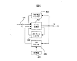
次に図5の符号化回路の構成及び動作を説明する。符号化回路51は、4−6変換器401、次ステートレジスタ402、DSVカウンタ406及び前符号語レジスタ403を有する。次ステートレジスタ402,DSVカウンタ406および前符号語レジスタ403は、初期状態では”0”に初期化されている。次ステートレジスタ402には、次の変換時使用されるステートが格納されている。前符号語レジスタは4−6変換器から出力される6ビット分の符号語が保持される。
【0032】
また,4−6変換器401から出力される符号列に従って、(1の数)×1+(0の数)×(−1)+1の値がDSVカウンタ406の値に加えられる。
目標値レジスタ407の値は1シンボルの変換毎にDSVカウンタから減算される。
【0033】
目標値レジスタ407には1シンボルあたりの制御目標DSV値が保持される。この例では制御目標を0.5としているが,それよりも小さな刻みでも制御可能なように,DSVカウンタは0.25単位の値を保持できるように,通常のLSBの下位に2ビット分(0.5と0.25の位)の余分のビットを持っている。目標値が減算されることにより,DSVレジスタには符号語のDSV値そのものではなくDSVと目標値の差Δが保持されることになる。
【0034】
4−6変換器401では、次ステートレジスタ402及びDSVカウンタ406の値と信号線404を通して4−6変換器401に入力されたユーザデータにより、図4に示すテーブルに従った変換が行われる。DSVの制御は以下の論理によって4−6変換時に行われる。
(1)次ステートレジスタの値が1または2でかつ入力データが0又は1の時:
DSVカウンタの値に変換表のDSV値を加えた値が0に近づくように、主変換表と副変換表の間で選択する。
(2)次ステートレジスタの値が3または4の時:
(a)ステート3と4の符号語のうち前符号語との接続部でd,k制約を満たす符号語を選択する。
(b)上記d,k制約を満たす符号語が2つ有る場合は,DSVカウンタの値に変換表のDSV値を加えた値が0に近づくように、主変換表と副変換表の間で選択する。この方法により1符号語あたりのDSVが目標値の0.5になるような符号を生成することが出来る。
【0035】
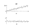
図7はこの符号回路により生成された符号のDSV値の変化と,DSVと目標値(1符号語あたり0.5)との差Δを示したものである。DSVが目標値の付近に制御されていることが分かる。
【0036】
図8は本実施例の符号化回路によって生成された符号語の信号スペクトルを示したものである。比較のために従来例である1−7変調の信号スペクトルを併記したが,本実施例の方式の方が低周波成分がより抑圧されていることが分かる。このため,記録再生時のサーボの安定性が良く,再生時には信号位相追従してクロックを生成するPLL回路や,レベルの変動に追従するレベル追従回路回路の追従帯域を高くしても信号そのものの影響で撹乱される心配がないため,ディスク回転変動などの低域のノイズ成分を効果的に抑圧する再生回路が容易に構成できる。すなわち高S/Nの再生が容易になる。
【0037】
図9は本実施例の符号を用いて,相変化型光ディスクに実際に記録を行い再生したときのエラーレートを示したものである。この試作ディスクのノイズをマーク部とスぺース部に分けて解析した結果を示したのが図16である。このディスクではスペース部分のノイズレベルがマーク部分に比較して約6dB高くなっているのが分かる。
【0038】
本実施例の符号を用いると前述のように1符号語あたりのDSVを約0.5に制御することが出来る。1符号語の長さは6であるため,マークとスペースの比に換算すると3.25:2.75になる(3.25−2.75=0.5)。これはマークのDuty比としては3.25/6×100=約54%に相当する。このとき平均ノイズレベルは図2より約0.5dB低減できる。もちろん,マークのDuty比を更に大きくする,すなわちスペースの割合を更に小さくすることで,平均ノイズレベルを更に低減できることは,図2からも明らかである。例えば,マークのDuty比が64%の場合,平均ノイズレベルを約1dB低減できる。
【0039】
なお,この例とは逆に,マーク部分のノイズレベルの方が,スペース部分と比較して,約6dB高いディスクを用いる場合には,マークのDuty比を約46%(=2.75/6×100)以下とすることで,同様に平均ノイズレベルを約0.5dB以上低減できることは言うまでもない。
【0040】
本実施例の符号を用いて,試作ディスク上で記録再生を行い,エラーレートを測定した。このときの記録再生条件は,波長405nmのレーザとNA0.85対物レンズを搭載した光学系を用い,トラックピッチ約0.28μmランドグルーブ構造のディスク上に,線密度0.09μm/bitとなるように記録した。このときの線速度は約4.5m/s,再生パワーは0.3mWであった。ちなみにこのときの記録容量は120mmディスクで約35GBに相当する。エラーレートの測定結果を見ると,本発明では図9で示したようにエラー率が約100万分の1となったが,従来の1−7変調を適用したところ図9で示したように約3桁悪いエラー率しか得られなかった。このときの2T繰り返し信号はどちらも2T=0.12μmであるためS/N比も同じで約18dBであった。この条件で,再生光を意図的に小さくすると,信号光量の低下に伴ってS/N比が劣化する。このときのS/N比とエラーレートの関係を調べた結果を実線で示した。本発明は同じS/N比に換算して,2dB近いエラー率低減効果があることが分かる,前述のノイズ低減効果自体は約0.5dBであったので,残りの1.5dBは低周波信号成分抑制効果に起因するものである。
(実施例2)
図10は本発明の別の実施例の符号化回路を示したものである。本実施例の符号は8ビットのユーザデータを9ビットに変換する8/9変換であり(0,8)RLL符号である。d=0であることから最短マークスペース長は1Tである。
【0041】
符号化回路50は,DSVカウンタ504,ラン長カウンタ503,接続ビット選択器505,合成出力回路50及び目標値レジスタ507より構成される。接続ビット選択器は入力ユーザデータ501,DSVカウンタ出力504,ラン長カウンタ503の値により直前の出力符号語502の入力ユーザデータの間の接続ビットを決定する
ラン長カウンタは直前の符号語の最後のラン長(連続するゼロの個数)をカウントし,保持している。DSVカウンタはNRZI変換後のDSV値を計算し保持しており,実施例1と同様に1シンボル=8bit毎に目標値レジスタ507に保持されたが目標値が減算される。
【0042】
接続ビット選択器の具体的な動作について説明する。接続ビット選択器は,直前のラン長カウンタの値と,入力ユーザデータの先頭部のラン長(連続するゼロの個数)の値を加算しさらに,1を加算した値を評価する。この値が8よりも大きくなる場合には接続ビットとして無条件に1を選択する。上記値が8以下の場合には,接続ビットとして1を選択した場合と,0を選択した場合のNRZI変換後のDSVの値を,直前のDSVの値と入力ユーザデータパターンから算出し,比較する。比較の結果,DSVが小さくなる方を接続ビットとして選択する。
【0043】
その後,選択された接続ビットとユーザデータが合成出力回路506によって合成され,NRZI変換回路508に送られ,NRZI変換回路508は隣接するビット同士の排他的論理和演算によりNRZI変換を行い記録系列509を出力する。この系では,8ビットの入力ユーザデータ後とに1ビットの接続ビットが付加されるため,出力ビットは9ビットとなり,符号化率は8/9となる。また,ラン長が8を越えないように接続ビットを選択する為,k=8となり,(0,8)RLL符号となっている。
【0044】
この例では,目標値として3.5から−3.5までの値を設定することが可能である。(この範囲外の場合符号空間が不足する為にDSVをコントロールすることが出来ない。)
本実施例の符号化回路は実施例1と同様に図3の記録再生装置の一部(符号化回路51)として用いることができる。本実施例の符号回路を目標値を2.5にしてとして動作させると,1シンボルあたりのマークとスペースのDutyの比は5.75:3.25となる(2.5=5.75−3.25)。1シンボルは9ビットの符号語に変化されるため,マークのDuty比は5.5/9×100%=約64%となる。したがって,実施例1の光ディスク(スペースの方がマークよりも6dB高い)を用いた場合,図2より約1dBのS/N比改善効果が得られることが分かる。
(実施例3)
本実施例では,実施例2の記録符号に,ユーザデータのスクランブルを組み合わせた例を示す。図11は記録データのフォーマットを示したものである。ユーザデータ(c)はスクランブルされた後,前述の8/9変換により,接続ビット71を8ビットあたり1ビット挿入されて(0,8)RLL符号に変換されて記録される。本実施例では,112バイトのユーザデータに1バイト“Seed”を付加してスクランブルを施し113バイトのデータとし,それを8/9変換で113×9=1017ビットの記録系列に変化する。各記録データ系列の先頭部には27ビット長の同期マーク(SYNC)が配置される。合計1044ビットにてSyncフレームが構成されている。Syncはデータ系列の10Tマークと10Tスペースの組の他,番号を表す部分からなり,番号の部分でSyncフレームの連続性を判定したり,エラー訂正ブロック内での位置を同定し同期を取るのに利用される。ここでは詳細は割愛するが,この例では640個のSyncフレームで一つのエラー訂正(ECC)ブロックが構成されている。ECCブロックは計71680バイトの元データが含まれ,これはこのうち65536バイトが実際にユーザが使えるデータで残りは,エラー訂正用のパリティやIDが含まれる。Sync等も含めたトータルのフォーマット効率は88.3%となっている。
【0045】
図13は本実施例のスクランブル回路を,図12はスクランブル回路の動作原理を示している。ユーザデータはまず先頭部に任意のSeedバイトを付加しその後,図13のスクランブル回路に入力される。その際,スクランブル回路は実行的に変換後のスクランブルデータと次のユーザデータバイトの間で演算を行うように動作する。このため,デスクランブル時にはその逆演算を行うだけでよく,この演算,隣接する2バイトのみスクランブルデータを用いるだけで行えたデスクランブル時にシードの値を知る必要がない。すなわちシードの値によらず固定のアルゴリズムでデスクランブルが可能である。このため,記録時にシードを任意に選んで記録することが出来る。
【0046】
本実施例では,記録時にスクランブルを任意に選べることを利用して,複数の種類Seedを用いて変調を試行し,その複数の変調データ系列のうち最もDSVのばらつきやラン長のばらつきが少ないものを選択して記録することが出来る。本実施例では,変調データ列の選択をSyncフレーム単位で行った。これにより,記録データ系列の一様性が向上する。図14は実施例2の符号をそのまま用いた場合と,本実施例のスクランブル方式を組み合わせた場合の記録符号のスペクトルを示したものである。本実施例の方式の方が低周波成分をより抑圧できている事がわかる。
【0047】
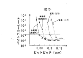
本実施例の記録符号・フォーマットを用いて記録再生を行った場合と,従来の通常の8/9変換(マークスペースDutyを1:1)に制御の場合と,さらに,前述の実施例2(Dutyを64%に制御)を用いた場合で再生特性の比較をおこなった。このときの記録再生条件は,波長405nmのレーザとNA0.85対物レンズを搭載した光学系を用い,トラックピッチ約0.25μmのランドグルーブ構造のディスク上に,線密度0.12μm/ビットから0.070μm/ビットまで変えて記録再生を行った。線速度は約4.5m/sである。再生パワーは0.3mWであった。
【0048】
結果を図15に示した。本実施例の方式が常にエラー率が低く,記録再生特性に優れていることが分かる。本実施例ではではエラー率が10−4になる時の線記録密度は0.08μm/ビットとなっている。このときの記録容量はフォーマット効率Mまで考慮して120mmディスクで約56GBに相当する。すなわち,本方式の適用により,従来比約1.4倍の密度向上効果があることがわかる。
【0049】
ここでのバイトエラー率はエラー訂正を行う前の値である。一般的なエラー訂正方式ではバイトエラー率10−2〜10−3のものを10―12以下程度まで抑圧する訂正能力を持っている。
【0050】
実際に本方式のスクランブルの前にユーザデータに任意のM系列などを掛け合わせるプリスクランブルを行っておく方が,スクランブル語のデータ系列の一様性が向上する為より望ましい。また,Seedデータは必ずしも1バイト分必要ではなく例えば,Syncデータの一部をSeedとして用いることも可能で有り,このようにしてフォーマット効率の向上を図ることが出来る。
(実施例4)
図17は,本発明の実施例における復調回路を示したものである。この復調回路は変換器601,電圧比較器602,積分器603及びローパスフィルタ604から構成されている。
【0051】
この例では,データは記録媒体に,マークとスペースの比が3.25:2.75になるように記録されている。これはマークのDuty比としては3.25/6×100=約54%に相当する。
【0052】
光ディスクから読み出された再生信号は,まず電圧比較器602に入力される。電圧比較器602には再生信号のほかに,電圧比較のための比較レベル,すなわち”0”,”1”の判定レベルが入力される。電圧比較器602では,チャネルクロック毎に再生信号と判定レベルとが比較され,再再生信号が判定レベルより小さい場合に”0”,大きい場合に”1”というようにデータ列が出力される。
【0053】
この例に用いられる相変化型記録媒体では,マーク部分の反射率が,スペース部分の反射率より低いため,再生信号レベルはマーク部分で低く,スペース部分で高くなる。このため,電圧比較器602の出力は,マーク部分では”0”,スペース部分では”1”となる。
【0054】
電圧比較器602から出力されたデータ列は,チャネルクロック毎に,変換器601に入力される。変換器601では,ある一定期間毎に入力された”0”の数と”1”の数の累積値がカウントされ,”0”の割合が,54%よりも小さい場合には,正の電圧レベルが出力され,逆に,上記の”0”の割合が54%よりも大きい場合には,負の電圧が出力される。変換器601の出力は,適当に定数が選ばれた積分器603及びローパスフィルタによって積算されて,上記の判定レベルとなり,上記の電圧比較器602に入力される。
【0055】
このようにして,上記の”0”の割合が54%よりも小さい場合には,上記の判定レベルが上がることによって,割合が大きくなり,逆に割合が54%より大きい場合には,判定レベルが下がることによって,割合が小さくなる。このため,”0”割合が54%に近づくように制御される。
【0056】
これにより,電圧比較器602の出力する”0”の割合が54%になるように制御されるため,上記の記録方法によってマークのDuty比が54%となるように記録されたデータを,正しく復調することができる。
(実施例5)
図18に,本発明の実施例における復調回路の別の例として,PRMLを用いた例を示す。この復調回路は変換器701,電圧加算器702,PRML復調器703,積分器704及びローパスフィルタ705から構成されており,上記の実施例4の復調回路における電圧比較器602を,電圧加算器702とPRML復調器703で構成されるブロックに置き換えたものとなっている。
【0057】
光ディスクから読み出された再生信号は,電圧加算器702に入力される。電圧加算器702にはもうひとつ,再生信号に加算する加算信号が入力される。再生信号は,電圧加算器702によって加算信号と加算されて出力され,PRML復調器703に入力される。この実施例で用いられているPRML復調器703は,上記の実施例1で,用いられているものと同じである。
【0058】
この例に用いられる相変化型記録媒体では,実施例4に用いられる記録媒体と同様に,マーク部分の反射率が,スペース部分の反射率より低いため,再生信号レベルはマーク部分で低く,スペース部分で高くなる。
【0059】
変換器701では,ある一定期間毎に入力された”0”の数と”1”の数の累積値がカウントされ,”0”の割合が,54%よりも小さい場合には,負の電圧レベルが出力され,逆に,上記の”0”の割合が54%よりも大きい場合には,正の電圧が出力される。
【0060】
変換器701の出力は,適当に定数が選ばれた積分器704及びローパスフィルタ705によって積算されて,上記の加算信号となり,上記の電圧比較器702に入力される。
【0061】
このようにして,上記の”0”の割合が54%よりも小さい場合には,上記の加算信号のレベルが下がることによって,割合が大きくなり,逆に割合が54%より大きい場合には,加算信号のレベルが上がることによって,割合が小さくなる。このため,”0”割合が54%に近づくように制御される。
【0062】
これにより電圧比較器702の出力する”0”の割合が54%になるように制御されるため,上記の記録方法によってマークのDuty比が54%となるように記録されたデータを正しく復調することができる。
【0063】
本発明の実施の形態及び効果は以上の実施例に限られるものではない。
【0064】
記録媒体は,上記の実施例で用いた相変化型に限られるものではなく,エンボスピットによって情報を記録する再生専用記録媒体を用いてもよい。また相変化型のようにスペース部分のノイズレベルがマーク部分のノイズレベルと比べて高いものに限られるものではなく,例えば色素や無機薄膜の追記型記録媒体,あるいは光磁気記録媒体のように,マーク部分のノイズレベルの方が高い傾向にある記録媒体を用いてもよい。実施例では,記録信号の変調方式として,(1,10)変調及び(0,8)変調を用いたが,例えばEMF及びEMFPluse の(2,7)変調を用いてもよい。実施例ではデータの再生にPR121を用いたが,他のクラスのものを使ってもよく,例えばPR1111,PR1221あるいはPR(−1,0,1)を使うこともできる。記録再生に用いるレーザの波長として,630−650nmのものを用いてもよい。またヘッドの開口比は,0.65や0.75でもよい。
【0065】
【発明の効果】
本発明によれば、媒体の持つS/Nを最大限に発揮することの出来る高S/N記録再生の記録再生方法を提供することが出来るため,高速かつ高密度光ディスクシステムの実現が可能となる。
【図面の簡単な説明】
【図1】本発明の記録マークとスペースの関係を説明する図。
【図2】本発明の原理説明図。
【図3】本発明の1実施例の装置構成を表す図。
【図4】本発明の1実施例の記録符号。
【図5】本発明の1実施例の符号化回路説明。
【図6】光ディスクのでマークとスペースでノイズが異なる原因を説明する図。
【図7】本発明でDSV制御の概念を示す図。
【図8】本発明の1実施例で低周波域スペクトルの抑制効果を示す図。
【図9】本発明の効果を表す図。
【図10】本発明の1実施例の符号化回路。
【図11】本発明の1実施例のデータフォーマットを説明する図。
【図12】本発明の1実施例のスクランブル装置の動作概念図。
【図13】本発明の1実施例のスクランブル装置の回路構成例。
【図14】本発明の1実施例で低周波域スペクトルの抑制効果を示す図。
【図15】本発明の効果を表す図。
【図16】本発明の一実施例記録媒体のノイズ分布を示す図。
【図17】本発明の一実施例の信号復調回路構成例。
【図18】本発明の一実施例の信号復調回路構成例。
【符号の説明】
1…記録媒体,2…記録再生ヘッド,6…上位装置,
21…光スポット,22…光ビーム,
23…対物レンズ,24…レンズ,25…レーザ光源,
31…アクチュエータ,
41…再生ブロック,42…アドレス検出回路,43…フォーマット制御回路,
44…復調回路,45…信号処理回路,46…復号回路,
51…符号化回路,52…レーザドライバ,
61…ホストインターフェース,
71…接続ビット,
401…4−6変換器,402…次ステートレジスタ,403…前符号語レジスタ,
404…ユーザデータ,406…DSVカウンタ,407…目標値レジスタ,
501…ユーザデータ,502…変換符号語,503…ラン長カウンタ,
504…DSVカウンタ,505…接続ビット選択器,506…出力合成回路,
507…目標値レジスタ,508…NRZI変換回路,509…記録ビット系列,
601…変換器,602…電圧比較器,603…積分器,604…ローパスフィルタ,
701…変換器,702…電圧加算器,703…PRML復調器,
704…積分器,705…ローパスフィルタ。[0001]
TECHNICAL FIELD OF THE INVENTION
The present invention relates to a method for recording information on an optical disc and a method for reproducing the recorded information.
[0002]
[Prior art]
In an optical disk system such as a CD or a DVD, a mark edge recording method is used for recording information. In this method, binary data “1” is assigned to a boundary (edge) between a recording mark and a space (inter-mark portion), and “0” is assigned to other portions. At this time, in order to perform high-density (high-efficiency) recording that exceeds the limit of the resolution of the optical spot on the optical disk, the run length in which the number of consecutive “0” s between “1” and “1” is limited A restriction code (RLL code) is used. Thus, high-density recording can be performed while keeping the length of the shortest mark and the shortest space longer than the resolution limit of light. For example, an EFM code used for CD (Compact Disk) and an EFMPlus code (or 8-16 code) used for DVD have a minimum mark / space length of 3T (T is a channel clock cycle). This is a run length limited code restricted to. These codes are disclosed, for example, in US Pat. No. 5,696,505.
[0003]
EFM code and EFMPlus (8-16 code) are (d, k) RLL codes, where d = 2 and k = 10. Here, d = 2 and k = 10 are the minimum value and the maximum value of the number of “0” s between “1” and “1” on the run length limited code. In actual recording, not an edge but a mark is recorded, so that "1" / "0" as a result of NRZI conversion is performed in correspondence with a mark / space. In the NRZI conversion, when the run length limited code is “1”, the code is inverted such as “1” → “0”, “0” → “1”, and when the run length limited code is “0”, Since the code is converted as it is, d + 1 is the minimum mark and space length. That is, the minimum mark and space lengths of the EFM code and the EFMPlus code were both 3 bits.
[0004]
As a typical example of the shortest run length d = 1, there is 1-7 modulation employed in a magneto-optical disk. Since d = 1, the shortest mark / space length is 2T.
[0005]
In recent years, optical disks have been required to have higher recording densities. For this reason, the adoption of a partial response maximum likelihood decoding (hereinafter abbreviated as PRML) in an optical disk device has been studied.
[0006]
2. Description of the Related Art Conventionally, in a magnetic disk device, PRML using a technology used in a communication field has been used to improve a recording density. Partial response (PR) is a method of reproducing data while compressing a necessary signal band by positively utilizing intersymbol interference (interference between reproduced signals corresponding to bits recorded adjacent to each other). is there. The Viterbi decoding method (ML) is a kind of a so-called re-likelihood sequence estimation method, and effectively utilizes a rule of inter-symbol interference of a reproduced waveform to reproduce data based on signal amplitude information over a plurality of times. I do.
[0007]
[Problems to be solved by the invention]
However, it has been difficult for conventional optical disks to record and reproduce data while achieving both high reliability and a low error rate.
[0008]
An object of the present invention is to provide an optical recording / reproducing system capable of always performing recording / reproducing with high reliability and a low error rate.
[0009]
[Means for Solving the Problems]
The present inventors have analyzed and studied the above conventional problems. In an optical disk, as shown in FIG. 6, the physical quality of a recording mark portion and that of a space portion are generally different from each other, so that the signal quality itself usually differs between the mark portion and the space portion. For example, in a prototype phase-change type recording medium, the space is recorded in a form of crystalline (polycrystalline) and the recorded part is amorphous, but the amorphous part has a very uniform physical structure. On the other hand, noise generally tends to increase in the space due to variations in the crystal axis of the polycrystal and scattering of light at crystal grain boundaries. FIG. 16 shows an analysis of the distribution of signal fluctuation components of the prototype phase change recording medium. In the figure, the portion where the mark is not described in the position is a space region. FIG. 16 shows that noise components are concentrated in the space. In this example, the noise in the space is about 6 dB higher than the mark. For this reason, even if a fine mark can be accurately formed, the signal quality is degraded due to signal fluctuation in a space portion, and as a result, high-speed and high-density recording / reproduction cannot be performed. As another example, a write-once optical disc uses a recording film such as a dye or an inorganic thin film to form a recording mark by utilizing recording, deformation of a substrate, diffusion of a material, or the like. When attempting to perform density recording, a minute recording mark cannot be stably formed, and therefore, the signal quality of the recording mark tends to be low. Also in this case, high-speed and high-density recording / reproduction becomes difficult as a result.
[0010]
Therefore, in the present invention, a mark recording code in which the ratio between the average mark length and the average space length is shifted from 1: 1 so as to increase the signal component on the side where the recording / reproducing signal quality is good among the mark and space portions. Applied.
[0011]
Since the mark length and the space length are the run length + 1 channel bit (1T), in other words, this corresponds to applying a code such that the average run length differs between the mark and the space part. That is, a first state and a second state different from the first state are formed on the recording film using the RLL coding rule. When recording such that information is provided at the boundary between the first state and the second state, the average run length of the RLL code when recording the first state is the same as that when recording the second state. Shorter. Here, in the case of phase change recording, the first state is crystalline and the second state is amorphous. In this case, since the noise in the space portion (crystal) is larger than the noise in the mark portion (amorphous) as described above, the average space length is set shorter than the average mark length as shown in FIG. Record the information.
[0012]
When the ratio between the average mark length and the average space length is shifted from 1: 1, if a mark having an extremely large number and a mark having a small number are mixed on a recording track, a low-frequency fluctuation of a reproduction signal occurs, and a servo system or a synchronous In order to adversely affect the system (PLL), it is desirable to control the ratio so that the ratio becomes a predetermined value determined in advance according to the characteristics of the medium. This is the same when discussing the average run length of the mark portion and the space portion.
[0013]
In order to control the ratio to a constant target value, a predetermined value is added to the cumulative value DSV (Digital Sum Value) when the mark portion is -1 and the space portion is 1 at regular intervals. It is simple to control to approach the value in terms of the device configuration.
[0014]
By performing such encoding, low frequency components included in the code can be suppressed low. However, since the ratio between the mark portion and the space portion is different, the DC component itself does not become zero but becomes a predetermined value.
[0015]
On the other hand, in the reproducing process, a process of obtaining a reproducing signal from a recording medium using a pickup head, a waveform equalizing process of correcting a frequency characteristic of the reproducing signal, a gain control process of setting the amplitude of the reproducing signal to a predetermined value, A process of determining "1" or "0" at a predetermined determination level to obtain a modulated data bit sequence, and a process of decoding the modulated data bit sequence according to a run length limited code rule to obtain digital information. When the number of “1” s contained in the bit string is N1 and the number of “0” s is N0, the value of the discrimination level is adaptively controlled so that the ratio R = N1 / N0 becomes a predetermined value.
[0016]
FIG. 2 shows how the signal quality is improved by changing the mark to space ratio. The difference in total noise level between the case where the noise in the space portion is 5 dB higher than the noise in the mark portion and the case where the noise in the space portion is 10 dB higher is calculated when the space / mark ratio is 1: 1. The signal fluctuation (noise) influence (total noise) from both the mark / space is expressed by the following equation.
[0017]
(Equation 1)
Pmark: Ratio of mark part
Pspace: ratio of space part
Nmark: noise level of mark part
Nspace: noise level in space
It is.
[0018]
According to FIG. 2, for example, in a system in which the noise level of the space portion is 10 dB higher than that of the mark portion, if the space ratio is reduced by 20% to 0.3, the noise level of about 2 dB can be reduced.
[0019]
In addition, after completing the invention of the present application, as a result of conducting a publicly known example investigation, JP-A-2000-163887 was found. This publication discloses that, for each of a bit string corresponding to a mark string and a bit string corresponding to a space, only a quantized value of a predetermined size within a range satisfying a minimum length and a maximum length of the RLL. It describes that the modulation data selected so as to have is selected and modulated, and a reproduction error is confirmed based on a quantization condition at the time of demodulation. However, this publication does not apply a code in which the average run length differs between the mark and the space portion as in the present application.
[0020]
BEST MODE FOR CARRYING OUT THE INVENTION
(Example 1)
FIG. 3 is a block diagram showing a schematic configuration of an optical disk device according to one embodiment of the present invention. As described below, the optical disk device may be used as a storage device of a computer system, or may be connected to a television and used as a stationary image / sound recording / reproducing device. Further, it may be used as a recording / reproducing device such as a portable video camera and a portable music reproducing device.
[0021]
In FIG. 3, the
[0022]
The
[0023]
At the time of reading data, the reflected light of the
[0024]
The reproduction signal input to the reproduction block 41 is first sent to a
[0025]
The obtained data sequence is subjected to a code conversion reverse to that of the
In the optical disk device, data recording and reproduction are performed according to the above procedure.
[0026]
In this embodiment, the
[0027]
The frequency of occurrence of an error is a function of the Euclidean distance, and an error having a larger Euclidean distance has a lower probability of occurrence. For example, the error occurrence probability of an error in which the square of the Euclidean distance is 4 is 4 × 10 -3 (10 n Indicates the power of 10), the probability of an error that the square of the Euclidean distance is 6 is approximately 6 × 10 -4 It is. When the S / N ratio and the error rate are good, the ratio of the error occurrence probability when the square of the Euclidean distance is 4 and when the square of the Euclidean distance is 6 tends to further increase. Therefore, if an error occurrence pattern with a small Euclidean distance can be theoretically eliminated by the run length limiting code, the error occurrence rate can be suppressed to a small value.
[0028]
When PR (121) is used, the error pattern in which the square of the Euclidean distance is 4 is ± (1, −1) or ± (1, −1,1 (−1,1)). m ), Both of which include ± (1, -1). Here, the error pattern is shown assuming that the mark / space (0/1) is ridden. When an error is determined for the
[0029]
The code of this embodiment is generated by the coding circuit of FIG. 5 using the conversion table shown in FIG. At this time, the shortest mark length and the shortest space length both have a function of being 2. The code string output from the encoded output 405 in FIG. 5 is written on the medium such that the 0 part is a mark and the 1 part is a space. The code according to the present invention is a (1,10) RLL code having a limit on a run length between edges when focusing on a boundary portion (edge) between a mark and a space.
[0030]
Hereinafter, the notations “0” and “1” of the data used in the embodiment represent data in the NRZ expression. That is, “0” and “1” directly correspond to a mark and a space.
[0031]
Next, the configuration and operation of the encoding circuit of FIG. 5 will be described. The
[0032]
Further, the value of (number of 1) × 1 + (number of 0) × (−1) +1 is added to the value of the
The value of the
[0033]
The
[0034]
In the 4-6
(1) When the value of the next state register is 1 or 2, and the input data is 0 or 1:
A selection is made between the main conversion table and the sub conversion table so that the value obtained by adding the DSV value of the conversion table to the value of the DSV counter approaches 0.
(2) When the value of the next state register is 3 or 4:
(A) Select a codeword satisfying the d and k constraints at the connection between the codewords of
(B) When there are two codewords satisfying the above d and k constraints, the value between the DSV counter and the DSV value of the conversion table is close to 0 so that the value between the main conversion table and the sub conversion table is close to zero. select. With this method, it is possible to generate a code such that the DSV per codeword becomes the target value of 0.5.
[0035]
FIG. 7 shows the change in the DSV value of the code generated by this code circuit and the difference Δ between the DSV and the target value (0.5 per codeword). It can be seen that DSV is controlled near the target value.
[0036]
FIG. 8 shows a signal spectrum of a code word generated by the encoding circuit according to the present embodiment. For comparison, a signal spectrum of 1-7 modulation, which is a conventional example, is also shown. It can be seen that the low frequency component is more suppressed in the method of the present embodiment. For this reason, the servo stability during recording and reproduction is good, and during reproduction, even if the tracking band of a PLL circuit that generates a clock by following the signal phase or a level tracking circuit that tracks a level change is increased, the signal itself is not changed. Since there is no fear of being disturbed by the influence, it is possible to easily configure a reproducing circuit that effectively suppresses low-frequency noise components such as disk rotation fluctuation. That is, reproduction at a high S / N becomes easy.
[0037]
FIG. 9 shows an error rate when actually recording and reproducing data on a phase change optical disk using the codes of the present embodiment. FIG. 16 shows the result of analyzing the noise of this prototype disk by dividing it into a mark portion and a space portion. In this disk, it can be seen that the noise level in the space portion is about 6 dB higher than that in the mark portion.
[0038]
By using the code of this embodiment, the DSV per codeword can be controlled to about 0.5 as described above. Since the length of one codeword is 6, it is 3.25: 2.75 (3.25-2.75 = 0.5) in terms of the ratio of mark to space. This corresponds to a mark duty ratio of 3.25 / 6 × 100 = about 54%. At this time, the average noise level can be reduced by about 0.5 dB from FIG. Of course, it is clear from FIG. 2 that the average noise level can be further reduced by further increasing the duty ratio of the mark, that is, further reducing the ratio of the space. For example, when the duty ratio of the mark is 64%, the average noise level can be reduced by about 1 dB.
[0039]
Contrary to this example, when using a disk in which the noise level of the mark portion is about 6 dB higher than that of the space portion, the duty ratio of the mark is set to about 46% (= 2.75 / 6). × 100), it is needless to say that the average noise level can be reduced by about 0.5 dB or more.
[0040]
Using the code of this example, recording and reproduction were performed on a prototype disk, and the error rate was measured. The recording / reproducing conditions at this time were such that an optical system equipped with a laser having a wavelength of 405 nm and an NA of 0.85 was used, and a linear density of 0.09 μm / bit was formed on a disk having a land / groove structure with a track pitch of about 0.28 μm. Recorded. At this time, the linear velocity was about 4.5 m / s, and the reproducing power was 0.3 mW. Incidentally, the recording capacity at this time is equivalent to about 35 GB for a 120 mm disk. Looking at the measurement results of the error rate, the error rate of the present invention was about 1 / 1,000,000 as shown in FIG. 9, but when the conventional 1-7 modulation was applied, the error rate was about 1 / 100,000 as shown in FIG. Only an error rate three orders of magnitude worse was obtained. Since the 2T repetition signals at this time were both 2T = 0.12 μm, the S / N ratio was the same and was about 18 dB. Under these conditions, if the reproduction light is intentionally reduced, the S / N ratio deteriorates as the signal light amount decreases. The result of examining the relationship between the S / N ratio and the error rate at this time is shown by a solid line. It can be seen that the present invention has an effect of reducing the error rate close to 2 dB when converted to the same S / N ratio. Since the above-described noise reducing effect itself is about 0.5 dB, the remaining 1.5 dB is a low-frequency signal. This is due to the component suppressing effect.
(Example 2)
FIG. 10 shows an encoding circuit according to another embodiment of the present invention. The code in this embodiment is an 8/9 conversion for converting 8-bit user data into 9 bits, and is a (0,8) RLL code. Since d = 0, the shortest mark space length is 1T.
[0041]
The
The run length counter counts and holds the last run length (the number of consecutive zeros) of the immediately preceding codeword. The DSV counter calculates and holds the DSV value after the NRZI conversion. Like the first embodiment, the DSV counter holds the DSV value every symbol = 8 bits in the
[0042]
A specific operation of the connection bit selector will be described. The connection bit selector adds the value of the immediately preceding run length counter to the value of the run length (the number of consecutive zeros) at the beginning of the input user data, and evaluates the value obtained by adding 1. If this value is greater than 8, 1 is unconditionally selected as the connection bit. When the above value is 8 or less, the DSV value after NRZI conversion when 1 is selected as the connection bit and when 0 is selected is calculated from the immediately preceding DSV value and the input user data pattern and compared. I do. As a result of the comparison, the one with the smaller DSV is selected as the connection bit.
[0043]
After that, the selected connection bit and the user data are combined by the combining
[0044]
In this example, a value from 3.5 to -3.5 can be set as the target value. (If it is outside this range, DSV cannot be controlled because the code space is insufficient.)
The encoding circuit of the present embodiment can be used as a part (encoding circuit 51) of the recording / reproducing apparatus of FIG. When the encoding circuit of this embodiment is operated with the target value set to 2.5, the duty ratio of the mark to the space per symbol is 5.75: 3.25 (2.5 = 5.75- 3.25). Since one symbol is changed to a 9-bit code word, the duty ratio of the mark is 5.5 / 9 × 100% = about 64%. Therefore, when the optical disk of Example 1 (the space is higher than the mark by 6 dB) is used, it can be seen from FIG. 2 that an S / N ratio improvement effect of about 1 dB can be obtained.
(Example 3)
In the present embodiment, an example is shown in which scrambling of user data is combined with the recording code of the second embodiment. FIG. 11 shows the format of the recording data. After the user data (c) is scrambled, the
[0045]
FIG. 13 shows the scramble circuit of this embodiment, and FIG. 12 shows the operation principle of the scramble circuit. User data is first added with an arbitrary Seed byte at the beginning, and then input to the scramble circuit of FIG. At this time, the scramble circuit operates so as to execute an operation between the scrambled data after the conversion and the next user data byte. For this reason, it is only necessary to perform the inverse operation at the time of descrambling, and there is no need to know the seed value at the time of the descrambling which can be performed only by using the scrambled data for only this adjacent two bytes. That is, descrambling can be performed with a fixed algorithm regardless of the seed value. For this reason, the seed can be arbitrarily selected and recorded at the time of recording.
[0046]
In the present embodiment, the modulation is attempted using a plurality of types of seeds by utilizing the arbitrary selection of the scramble at the time of recording, and the modulation data sequence having the least variation in the DSV and the variation in the run length among the plurality of modulation data sequences is used. Can be selected and recorded. In the present embodiment, the selection of the modulation data sequence is performed in units of Sync frames. This improves the uniformity of the recording data sequence. FIG. 14 shows the spectrum of the recording code when the code of the second embodiment is used as it is and when the scrambling method of the present embodiment is combined. It can be seen that the method of the present embodiment can suppress low frequency components more.
[0047]
The case where recording / reproducing is performed using the recording code / format of the present embodiment, the case of conventional 8/9 conversion (mark space Duty is 1: 1) control, and the case of the second embodiment described above. (Duty was controlled to 64%), and the reproduction characteristics were compared. The recording / reproducing conditions at this time are as follows: an optical system equipped with a laser having a wavelength of 405 nm and an NA of 0.85 objective lens, and a linear density of 0.12 μm / bit on a disc having a land / groove structure having a track pitch of about 0.25 μm. Recording / reproduction was performed by changing to 0.070 μm / bit. The linear velocity is about 4.5 m / s. The reproduction power was 0.3 mW.
[0048]
The results are shown in FIG. It can be seen that the method of the present embodiment always has a low error rate and is excellent in recording / reproducing characteristics. In this embodiment, the error rate is 10 -4 At which the linear recording density is 0.08 μm / bit. The recording capacity at this time is equivalent to about 56 GB for a 120 mm disk in consideration of the format efficiency M. In other words, it can be seen that the application of this method has a density improvement effect of about 1.4 times that of the conventional method.
[0049]
The byte error rate here is a value before error correction is performed. In a general error correction method, the byte error rate is 10 -2 -10 -3 10 things ―12 It has the correction ability to suppress to the following degree.
[0050]
It is more desirable to perform pre-scramble, in which user data is multiplied by an arbitrary M-sequence or the like before scrambling in the present method, since the uniformity of the data sequence of the scrambled word is improved. Further, the seed data is not necessarily required for one byte. For example, a part of the sync data can be used as seed, and thus the format efficiency can be improved.
(Example 4)
FIG. 17 shows a demodulation circuit according to the embodiment of the present invention. This demodulation circuit includes a
[0051]
In this example, data is recorded on a recording medium such that the ratio of mark to space is 3.25: 2.75. This corresponds to a mark duty ratio of 3.25 / 6 × 100 = about 54%.
[0052]
The reproduction signal read from the optical disk is first input to the
[0053]
In the phase change recording medium used in this example, the reflectance of the mark portion is lower than the reflectance of the space portion, so that the reproduction signal level is low in the mark portion and high in the space portion. Therefore, the output of the
[0054]
The data string output from the
[0055]
In this way, when the ratio of “0” is smaller than 54%, the above-mentioned judgment level is increased, so that the ratio is increased. Conversely, when the ratio is larger than 54%, the judgment level is increased. Decreases, the ratio decreases. Therefore, control is performed so that the “0” ratio approaches 54%.
[0056]
As a result, the ratio of “0” output from the
(Example 5)
FIG. 18 shows an example using PRML as another example of the demodulation circuit in the embodiment of the present invention. This demodulation circuit includes a
[0057]
The reproduction signal read from the optical disk is input to the
[0058]
In the phase change recording medium used in this example, the reflectance of the mark portion is lower than the reflectance of the space portion, as in the recording medium used in the fourth embodiment. Higher in part.
[0059]
The
[0060]
The output of the
[0061]
In this way, when the ratio of "0" is smaller than 54%, the level increases as the level of the addition signal decreases. Conversely, when the ratio is larger than 54%, As the level of the addition signal increases, the ratio decreases. Therefore, control is performed so that the “0” ratio approaches 54%.
[0062]
As a result, the ratio of “0” output from the
[0063]
Embodiments and effects of the present invention are not limited to the above embodiments.
[0064]
The recording medium is not limited to the phase change type used in the above embodiment, and a read-only recording medium that records information by emboss pits may be used. In addition, the noise level in the space portion is not limited to that higher than the noise level in the mark portion as in the phase change type. For example, as in a write-once recording medium of a dye or an inorganic thin film or a magneto-optical recording medium, A recording medium in which the noise level of the mark portion tends to be higher may be used. In the embodiment, the (1, 10) modulation and the (0, 8) modulation are used as the modulation method of the recording signal. However, for example, the (2, 7) modulation of EMF and EMFPlus may be used. In the embodiment, PR121 is used for data reproduction. However, data of another class may be used. For example, PR1111, PR1221 or PR (-1, 0, 1) may be used. The wavelength of a laser used for recording and reproduction may be 630 to 650 nm. The opening ratio of the head may be 0.65 or 0.75.
[0065]
【The invention's effect】
According to the present invention, it is possible to provide a recording / reproducing method of high S / N recording / reproducing capable of maximizing the S / N possessed by a medium, thereby realizing a high-speed and high-density optical disk system. Become.
[Brief description of the drawings]
FIG. 1 is a view for explaining the relationship between recording marks and spaces according to the present invention.
FIG. 2 is a diagram illustrating the principle of the present invention.
FIG. 3 is a diagram illustrating an apparatus configuration according to an embodiment of the present invention.
FIG. 4 shows recording codes according to an embodiment of the present invention.
FIG. 5 illustrates an encoding circuit according to an embodiment of the present invention.
FIG. 6 is a view for explaining the cause of noise difference between a mark and a space in an optical disc.
FIG. 7 is a diagram showing the concept of DSV control in the present invention.
FIG. 8 is a diagram showing a suppression effect of a low frequency band spectrum in one embodiment of the present invention.
FIG. 9 is a diagram illustrating an effect of the present invention.
FIG. 10 shows an encoding circuit according to one embodiment of the present invention.
FIG. 11 is a view for explaining a data format according to an embodiment of the present invention.
FIG. 12 is an operation conceptual diagram of the scramble device according to one embodiment of the present invention;
FIG. 13 is a circuit configuration example of a scrambler according to one embodiment of the present invention.
FIG. 14 is a view showing the effect of suppressing a low frequency band spectrum in one embodiment of the present invention.
FIG. 15 is a diagram showing effects of the present invention.
FIG. 16 is a diagram showing a noise distribution of a recording medium according to an embodiment of the present invention.
FIG. 17 is a configuration example of a signal demodulation circuit according to an embodiment of the present invention.
FIG. 18 is a configuration example of a signal demodulation circuit according to an embodiment of the present invention.
[Explanation of symbols]
DESCRIPTION OF
21 ... light spot, 22 ... light beam,
23 ... objective lens, 24 ... lens, 25 ... laser light source,
31 ... actuator,
41 ... reproduction block, 42 ... address detection circuit, 43 ... format control circuit,
44 demodulation circuit, 45 signal processing circuit, 46 decoding circuit,
51: coding circuit, 52: laser driver,
61 ... host interface,
71 ... connection bit,
401 ... 4-6 converter, 402 ... next state register, 403 ... pre-codeword register,
404: user data, 406: DSV counter, 407: target value register,
501 user data, 502 conversion codeword, 503 run length counter,
504
507: target value register, 508: NRZI conversion circuit, 509: recording bit sequence,
601: converter, 602: voltage comparator, 603: integrator, 604: low-pass filter,
701: converter, 702: voltage adder, 703: PRML demodulator,
704: an integrator, 705: a low-pass filter.
Claims (10)
前記第1の状態を記録するときのRLL符号の平均ラン長が、第2の状態を記録するときのそれよりも短いようにして、情報を記録することを特徴とする情報記録方法。Using a RLL coding rule, a first state and a second state different from the first state are formed on a recording film, and information is written at a boundary between the first state and the second state. An information recording method for recording information to have
An information recording method, wherein information is recorded such that an average run length of an RLL code when recording the first state is shorter than that when recording the second state.
前記”1”に対応する状態と前記”0”に対応する状態のノイズレベルが異なっており,
前記”1”に対応する状態と前記”0”に対応する状態の内,ノイズレベルの小さい状態を,より多く前記情報記録媒体に記録する変調符号を用いて、情報を記録することを特徴とする情報記録方法。An information recording method for recording a state corresponding to data "1" and a state corresponding to "0" as different physical states in an information recording medium in NRZ expression,
The noise level of the state corresponding to “1” and the noise level of the state corresponding to “0” are different,
Information is recorded by using a modulation code for recording more information on the information recording medium in a state having a lower noise level among the state corresponding to “1” and the state corresponding to “0”. Information recording method to be performed.
ユーザデータビット列を変調データビット列に変換する場合に,
前記変調データビット列に含まれる”1”の数をN1,”0”の数をN0とし,
前記情報記録媒体の”1”に対応する状態のノイズレベルDN1と”0”に対応する状態のノイズレベルDN0として
DN1<DN0の場合はN1>N0,
DN1>DN0の場合はN1<N0,
かつ,
比率R=N1/N0を略一定にするような変調符号を用いることを特徴とする請求項4記載の情報記録方法。A run length limited code as the modulation code;
When converting a user data bit string into a modulated data bit string,
The number of "1" included in the modulated data bit string is N1, and the number of "0" is N0,
The noise level DN1 in the state corresponding to "1" and the noise level DN0 in the state corresponding to "0" of the information recording medium are N1> N0 when DN1 <DN0,
If DN1> DN0, N1 <N0,
And,
5. The information recording method according to claim 4, wherein a modulation code that makes the ratio R = N1 / N0 substantially constant is used.
前記再生信号を復号して,ディジタル情報を得、前記情報を再生することを特徴とする情報再生方法。The average run length of the RLL code when recording the first state on the recording film is shorter than that when recording the second state, so that the first state and the second state can be compared. A reproduction signal is obtained by irradiating light to an information recording medium recorded so that information is provided at a boundary,
An information reproducing method, comprising: decoding the reproduced signal to obtain digital information; and reproducing the information.
前記再生信号を,周波数特性補正を行う波形等化を行う工程と,
前記再生信号の振幅を所定の値にするゲイン制御を行う工程と,
前記再生信号を所定の判別レベルにより,”1”,”0”を判別して,変調データビット列を得る工程と,
前記変調データビット列をラン長制限符号規則により復号して,ディジタル情報を得る工程を有し,
前記変調データビット列に含まれる”1”の数をN1,”0”の数をN0としたとき,比率R=N1/N0が予め定めた値になるように,前記,判別レベルの値を制御することを特徴とする請求項9記載の情報再生方法。The step of reproducing the information,
Performing a waveform equalization for correcting the frequency characteristic of the reproduced signal;
Performing gain control to set the amplitude of the reproduction signal to a predetermined value;
A step of discriminating the reproduced signal between "1" and "0" based on a predetermined discrimination level to obtain a modulated data bit sequence;
Decoding the modulated data bit string according to a run length limited code rule to obtain digital information;
When the number of “1” s contained in the modulated data bit string is N1 and the number of “0” s is N0, the value of the discrimination level is controlled so that the ratio R = N1 / N0 becomes a predetermined value. 10. The information reproducing method according to claim 9, wherein
Priority Applications (2)
| Application Number | Priority Date | Filing Date | Title |
|---|---|---|---|
| JP2002298229A JP2004134018A (en) | 2002-10-11 | 2002-10-11 | Information recording method and reproduction method |
| US10/370,479 US6737996B2 (en) | 2002-10-11 | 2003-02-24 | Information recording and reproducing method |
Applications Claiming Priority (1)
| Application Number | Priority Date | Filing Date | Title |
|---|---|---|---|
| JP2002298229A JP2004134018A (en) | 2002-10-11 | 2002-10-11 | Information recording method and reproduction method |
Publications (2)
| Publication Number | Publication Date |
|---|---|
| JP2004134018A true JP2004134018A (en) | 2004-04-30 |
| JP2004134018A5 JP2004134018A5 (en) | 2005-08-11 |
Family
ID=32064210
Family Applications (1)
| Application Number | Title | Priority Date | Filing Date |
|---|---|---|---|
| JP2002298229A Pending JP2004134018A (en) | 2002-10-11 | 2002-10-11 | Information recording method and reproduction method |
Country Status (2)
| Country | Link |
|---|---|
| US (1) | US6737996B2 (en) |
| JP (1) | JP2004134018A (en) |
Cited By (1)
| Publication number | Priority date | Publication date | Assignee | Title |
|---|---|---|---|---|
| JP2006236419A (en) * | 2005-02-22 | 2006-09-07 | Toshiba Corp | Storage medium, reproducing method and recording method |
Families Citing this family (11)
| Publication number | Priority date | Publication date | Assignee | Title |
|---|---|---|---|---|
| JP2004213767A (en) * | 2002-12-27 | 2004-07-29 | Toshiba Corp | Data conversion device and data conversion method |
| US6897792B1 (en) * | 2003-05-21 | 2005-05-24 | Marvell International Ltd. | Reducing number of consecutive ones in data-dependent scrambler |
| US7475331B1 (en) | 2003-10-07 | 2009-01-06 | Marvell International Ltd. | Data dependent scrambler with improved global constraint |
| JP3965385B2 (en) * | 2003-12-24 | 2007-08-29 | 株式会社日立製作所 | DVD recording method and DVD recording apparatus |
| TWI260611B (en) * | 2003-12-26 | 2006-08-21 | Ind Tech Res Inst | Encoding method of recording media |
| US20070165493A1 (en) * | 2004-01-14 | 2007-07-19 | Koninklijke Philips Electronic, N.V. | Method, apparatus and record carrier with average-runlength preserving code for improved readout parameter control |
| JP4353023B2 (en) * | 2004-07-30 | 2009-10-28 | 株式会社日立製作所 | Test writing method, information recording method |
| TWI267828B (en) * | 2004-11-12 | 2006-12-01 | Ind Tech Res Inst | Encoding apparatus with fast look-ahead path |
| WO2010118785A1 (en) * | 2009-04-17 | 2010-10-21 | Abb Research Ltd | A supervisory control system for controlling a technical system, a method and computer program products |
| JP5689498B2 (en) * | 2013-05-08 | 2015-03-25 | ファナック株式会社 | Serial communication control circuit |
| JP2015035240A (en) * | 2013-08-08 | 2015-02-19 | 日立コンシューマエレクトロニクス株式会社 | Channel bit word processor, prml decoder, optical information recording reproducer |
Family Cites Families (8)
| Publication number | Priority date | Publication date | Assignee | Title |
|---|---|---|---|---|
| BR9506787A (en) | 1994-02-15 | 1997-09-16 | Philips Electronics Nv | Processes for converting a series of words of m-bit information into a modulated signal and for producing a recording medium encoder devices recording decoder and reading signal and recording medium |
| DE19715274A1 (en) * | 1997-04-12 | 1998-10-15 | Thomson Brandt Gmbh | Read and write system for optical disc |
| KR100354175B1 (en) | 1998-11-20 | 2002-09-28 | 엘지전자 주식회사 | A method and an apparatus for modulating/demodulating data and a recording medium |
| JP4075185B2 (en) * | 1999-01-29 | 2008-04-16 | 松下電器産業株式会社 | Optical information recording / reproducing method and optical information recording / reproducing apparatus |
| US6377532B1 (en) * | 2000-11-21 | 2002-04-23 | Daewoo Electronics Co., Ltd. | Run-length limited encoding method and apparatus for use in a high density optical storage system |
| EP1758118B1 (en) * | 2000-12-26 | 2008-03-19 | Matsushita Electric Industrial Co., Ltd. | Recording of additional data with linking frames and various synchronization signals |
| JP4451004B2 (en) * | 2001-02-28 | 2010-04-14 | シャープ株式会社 | Optical regenerator |
| WO2003094158A1 (en) * | 2002-05-01 | 2003-11-13 | Lg Electronics Inc. | High-density read-only optical disc, and optical disc apparatus and method using the same |
-
2002
- 2002-10-11 JP JP2002298229A patent/JP2004134018A/en active Pending
-
2003
- 2003-02-24 US US10/370,479 patent/US6737996B2/en not_active Expired - Lifetime
Cited By (1)
| Publication number | Priority date | Publication date | Assignee | Title |
|---|---|---|---|---|
| JP2006236419A (en) * | 2005-02-22 | 2006-09-07 | Toshiba Corp | Storage medium, reproducing method and recording method |
Also Published As
| Publication number | Publication date |
|---|---|
| US6737996B2 (en) | 2004-05-18 |
| US20040070524A1 (en) | 2004-04-15 |
Similar Documents
| Publication | Publication Date | Title |
|---|---|---|
| US7826323B2 (en) | Reproducing apparatus and method with reduced bit error rate | |
| JP2002237036A (en) | Information recording method, reproduction method and information recording device | |
| US7519119B2 (en) | Method and apparatus of converting a series of data words into a modulated signal | |
| US6737996B2 (en) | Information recording and reproducing method | |
| JP4407461B2 (en) | Optical disk device | |
| US7016287B2 (en) | Method and apparatus of modulating/demodulating data for an optical recording medium | |
| US6922384B2 (en) | Information reproducing apparatus | |
| JP4095487B2 (en) | Information reproducing method and information reproducing apparatus using the same | |
| US8004443B2 (en) | Information readout apparatus and information reproducing method | |
| US6268812B1 (en) | Optical rotating recording medium, data recording method, recording apparatus and reproducing apparatus | |
| CN1108013C (en) | Modulation method, recording method, reproducing method, recording and reproducing apparatus, recording and reproducing method, and reproducing apparatus | |
| CN1942966B (en) | DC Control Coding for Optical Storage Systems | |
| WO2007010994A1 (en) | Digital signal reproducing device | |
| JP4501960B2 (en) | Viterbi detector and information reproducing apparatus | |
| KR100565039B1 (en) | Optical Disc RL Modulation and Demodulation Method | |
| JPWO2006100981A1 (en) | Information recording medium, information reproducing apparatus, and information reproducing method | |
| KR100372923B1 (en) | Modulation method for high density DVD | |
| JP2002208229A (en) | Multi-level recording modem | |
| JP4253196B2 (en) | Information recording method, information reproducing method, and information recording medium | |
| JP3811258B2 (en) | Information reproducing method and apparatus | |
| Hu et al. | PRML detection of multi-level DVD channels with run-length-limited modulation | |
| Bhagavatula et al. | Signal Processing Participants | |
| JP3761036B2 (en) | Recording medium reproducing apparatus, recording medium reproducing method, and optical disc | |
| Kato et al. | Performance evaluation of asymmetrical run-length-limited code for optical disks | |
| JP2002237137A (en) | Optical disk device and run length limited code for optical disk device |
Legal Events
| Date | Code | Title | Description |
|---|---|---|---|
| A521 | Request for written amendment filed |
Free format text: JAPANESE INTERMEDIATE CODE: A523 Effective date: 20050124 |
|
| A621 | Written request for application examination |
Free format text: JAPANESE INTERMEDIATE CODE: A621 Effective date: 20050124 |
|
| RD01 | Notification of change of attorney |
Free format text: JAPANESE INTERMEDIATE CODE: A7421 Effective date: 20060420 |
|
| A131 | Notification of reasons for refusal |
Free format text: JAPANESE INTERMEDIATE CODE: A131 Effective date: 20070313 |
|
| A521 | Request for written amendment filed |
Free format text: JAPANESE INTERMEDIATE CODE: A523 Effective date: 20070425 |
|
| A02 | Decision of refusal |
Free format text: JAPANESE INTERMEDIATE CODE: A02 Effective date: 20070529 |