JP2004138917A - Optical fiber cord and optical fiber cord processing method when optical connector is attached - Google Patents
Optical fiber cord and optical fiber cord processing method when optical connector is attached Download PDFInfo
- Publication number
- JP2004138917A JP2004138917A JP2002305042A JP2002305042A JP2004138917A JP 2004138917 A JP2004138917 A JP 2004138917A JP 2002305042 A JP2002305042 A JP 2002305042A JP 2002305042 A JP2002305042 A JP 2002305042A JP 2004138917 A JP2004138917 A JP 2004138917A
- Authority
- JP
- Japan
- Prior art keywords
- tube
- optical fiber
- optical
- heat
- optical connector
- Prior art date
- Legal status (The legal status is an assumption and is not a legal conclusion. Google has not performed a legal analysis and makes no representation as to the accuracy of the status listed.)
- Granted
Links
Images





Landscapes
- Mechanical Coupling Of Light Guides (AREA)
- Light Guides In General And Applications Therefor (AREA)
Abstract
【課題】光ファイバの被覆チューブから出た部分の保護を確実にする。
【解決手段】例えば予め工場で、例えば2本の被覆チューブ11の端部全体に熱収縮チューブ15の一端側を被せかつ加熱により密着固定し、かつ、保護チューブ13の後端側を熱収縮チューブ15の他端側に挿入しておく。光コネクタの現場付け作業では、保護チューブ13を熱収縮チューブ15の奥までスライドさせた状態で、光コネクタ5に光ファイバコード11の光ファイバ11aを取り付けた後、保護チューブ13を光コネクタ5側にスライドさせ、保護チューブ13を熱収縮チューブ15あるいは光コネクタ5側に粘着テープ等で固定する。被覆チューブ11bから露出させた光ファイバ11aの全体を保護チューブ13および熱収縮チューブ15で覆って保護できる。保護テープ処理部のある従来方法と比べて、光ファイバの保護が良好であり、現場作業も簡略化される。
【選択図】 図1An object of the present invention is to ensure protection of a portion of an optical fiber coming out of a coating tube.
For example, one end of a heat-shrinkable tube (15) is placed over the entire end of, for example, two coated tubes (11) and fixed tightly by heating, and the rear end of a protective tube (13) is heat-shrinkable. 15 to the other end. In the work of attaching the optical connector to the optical connector, after attaching the optical fiber 11a of the optical fiber cord 11 to the optical connector 5 with the protective tube 13 slid to the depth of the heat shrinkable tube 15, the protective tube 13 is connected to the optical connector 5 side. Then, the protection tube 13 is fixed to the heat shrink tube 15 or the optical connector 5 side with an adhesive tape or the like. The entire optical fiber 11a exposed from the coating tube 11b can be covered and protected by the protection tube 13 and the heat shrink tube 15. As compared with the conventional method having a protective tape processing unit, the protection of the optical fiber is better and the on-site work is simplified.
[Selection diagram] Fig. 1
Description
【0001】
【発明に属する技術分野】
この発明は、被覆チューブから露出させた光ファイバに保護チューブを被せた光ファイバコード、および、この種の光ファイバコードについての光コネクタ取付時の光ファイバコード処理方法に関する。
【0002】
【従来の技術】
図8、図9に示すように、嵌合ピン位置合わせ方式のフェルール1とメカニカルスプライス2とを一体化した光コネクタ本体部3をハウジング4内に収容してなる光コネクタ5は、現場付けの光コネクタとして用いられている。6は後部ハウジング、7はコイルバネ、8はゴムブーツである。その他、詳細構造は本発明の実施形態の説明で合わせて説明する。前記フェルール1は、一般にMTコネクタと称されているF12形多心光ファイバコネクタ(JIS C 5981)用のフェルールに類する構造であるが小形のもので、ミニMTコネクタとも称されており、内蔵光ファイバ10を内蔵しかつ接続端面を研磨済みである。また、図示例のフェルール1は2心、すなわち光コネクタ5は2心光コネクタであり、2本の単心光ファイバコード11の各光ファイバ11aと2本の内蔵光ファイバ10とがメカニカルスプライス2内でそれぞれ突き合わせ部接続される。この種の光コネクタ5は、一般にMTRJコネクタと称されているものである。なお、図8において、各2本の光ファイバ11aおよび内臓光ファイバ10はいずれも単なる線で表している。また、メカニカルスプライス2内の光ファイバ11aと内蔵光ファイバ10との突き合わせ接続部は、両者を区別するために互いに離間させて記載している。
【0003】
前記光コネクタ5に現場付けで光ファイバコード10を取り付ける場合、単心光ファイバコード11の被覆チューブ11bを除去して光ファイバ11aを適宜の長さだけ露出させた後、この光ファイバ11aとフェルール1の内蔵光ファイバ10とをメカニカルスプライス2内で接続するが、光ファイバ11aの露出部分を保護するために、2本の光ファイバ11a全体に別途塩化ビニル等の保護チューブ13’を被せることが行われている。
【0004】
上記の光ファイバコード取付作業において、光ファイバコード11の光ファイバ11aと内蔵光ファイバ10とをメカニカルスプライス2内で突き合わせ接続する際、各光ファイバ11aはある程度の長さ部分がフリーな状態で露出していなければ、そのメカニカルスプライス接続作業は困難である。このため、2本の光ファイバ11aを収容する保護チューブ13’は、図8、図9に示すように光ファイバ11aのメカニカルスプライス接続を済ませた状態で、光ファイバ11aの被覆チューブ13から露出した部分全長を覆うことはできず、保護チューブ13の両側に光ファイバ11aが露出する。このため、保護チューブ13’の両側の光ファイバ11a露出部に保護テープ14を巻いて、この光ファイバ11a露出部の保護処理をしていた。
【0005】
【発明が解決しようとする課題】
上記の光ファイバコード取付作業では、保護チューブ13’の両側に生じる光ファイバ11aの露出部に保護テープ14を巻き付ける保護テープ処理が煩雑であるとともに、この保護テープ処理で充分良好な保護性能が確保できない場合も生じる。
本発明は上記従来の欠点を解消するためになされたもので、光ファイバコードの被覆チューブから露出させた光ファイバに保護チューブを被せた状態で、当該光ファイバを光コネクタに取り付ける場合に、煩雑かつ不十分になり勝ちな保護テープ処理によらずに、光ファイバ露出部の保護を良好にかつ能率的に行なうことができる光ファイバコード、および光コネクタ取付時の光ファイバコード処理方法を提供することを目的とする。
【0006】
【課題を解決するための手段】
上記課題を解決する請求項1の発明は、被覆チューブから露出させた光ファイバに保護チューブを被せた光ファイバコードであって、
前記被覆チューブの端部に熱収縮チューブの一端側を被せかつ加熱により密着固定し、この熱収縮チューブの他端側に前記保護チューブの後端側を挿入したことを特徴とする。
【0007】
請求項2の発明は、複数本の光ファイバコードにおける各被覆チューブから露出させた複数本の光ファイバの全体に保護チューブを被せた光ファイバコードであって、
前記複数本の被覆チューブの端部全体に熱収縮チューブの一端側を被せかつ加熱により密着固定し、この熱収縮チューブの他端側に前記保護チューブの後端側を挿入したことを特徴とする。
【0008】
請求項3は、光ファイバコードの被覆チューブから露出させた光ファイバに保護チューブを被せた場合における光コネクタ取付時の光ファイバコード処理方法であって、
予め、前記被覆チューブの端部に熱収縮チューブの一端側を被せかつ加熱により密着固定し、かつ、保護チューブの後端側を前記熱収縮チューブの他端側に挿入しておき、光ファイバコードの光ファイバを光コネクタに取り付けた後、保護チューブを光コネクタ側にスライドさせて、被覆チューブから露出させた光ファイバの全体を保護チューブおよび熱収縮チューブで覆うことを特徴とする。
【0009】
請求項4は、複数本の光ファイバコードにおける各被覆チューブから露出させた複数本の光ファイバの全体に保護チューブを被せた場合における光コネクタ取付時の光ファイバコード処理方法であって、
予め、前記複数本の被覆チューブの端部全体に熱収縮チューブの一端側を被せかつ加熱により密着固定し、かつ、保護チューブの後端側を前記熱収縮チューブの他端側に挿入しておき、複数本の光ファイバコードの光ファイバを多心の光コネクタに取り付けた後、保護チューブを光コネクタ側にスライドさせて、被覆チューブから露出させた光ファイバの全体を保護チューブおよび熱収縮チューブで覆うことを特徴とする。
【0010】
請求項5は、請求項3又は4において、保護チューブを光コネクタ側にスライドさせた後、保護チューブを熱収縮チューブ又は光コネクタ又はその両方に粘着テープで固定することを特徴とする。
【0011】
請求項6は、請求項4における光コネクタが、嵌合ピン位置合わせ方式の多心のフェルールとメカニカルスプライスとを一体化した光コネクタ本体部をハウジング内に収容してなる現場付け用の多心の光コネクタであることを特徴とする。
【0012】
請求項7は、請求項2における熱収縮チューブが、複数本の被覆チューブの端部全体に被せる部分の径を、保護チューブを挿入する部分の径より大きくした段付き形状をなすことを特徴とする。
【0013】
【発明の実施の形態】
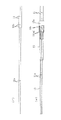
図1は本発明の一実施形態の光ファイバコード11、および光コネクタ取付時の光ファイバコード処理方法を説明する図である。この光ファイバコード11を光コネクタ5に取り付ける際の手順のうち、予め工場で行う作業を図2(イ)、(ロ)に、現場作業の前半を図3(ハ)、(ニ)に、後半を図4(ホ)〜(ト)に示す。
これらの図において、光コネクタ5は、嵌合ピン位置合わせ方式のフェルール1とメカニカルスプライス2とを一体化した光コネクタ本体部3をハウジング4内に収容してなる構造であり、現場付けの光コネクタとして用いられるものである。詳細は後述するが、6は後部ハウジング、7はコイルバネ、8はゴムブーツである。前記フェルール1は、一般にMTコネクタと称されているF12形多心光ファイバコネクタ(JIS C 5981)用のフェルールに類する構造で小形のもので、ミニMTコネクタとも称されており、内蔵光ファイバ10を内蔵しかつ接続端面を研磨済みである。また、図示例のフェルール1は2心、すなわち光コネクタ5は2心光コネクタであり、2本の単心光ファイバコード11の各光ファイバ11aと2本の内蔵光ファイバ10とがメカニカルスプライス2内でそれぞれ突き合わせ部接続される。この種の光コネクタ5は、一般にMTRJコネクタと称されているものである。なお、図2〜図4において、各2本の光ファイバ11aおよび内臓光ファイバ10はいずれも単なる線で表している。また、図4において、メカニカルスプライス2内の光ファイバ11aと内蔵光ファイバ10との突き合わせ接続部は、両者を区別するために互いに離間させて記載している。
また、図示例の光ファイバコード11は、樹脂製の被覆チューブ11b内に光ファイバ11aを収容したものである。
【0014】
上記光コネクタ5に光ファイバコード11を取り付ける作業を図2〜図4を参照して説明する。
予め工場にて、光ファイバコード11の被覆チューブ11bに熱収縮チューブ15を加熱により固定しておく。
すなわち、まず、図2(イ)のように、2本の単心光ファイバコード11の各被覆チューブ11bをそれぞれ一定長さだけ除去して、2本の光ファイバ11aを一定長さだけ露出させる。この露出長さは、光ファイバ11aをメカニカルスプライス2内で内蔵光ファイバ10と突き合わせ接続する際の作業、あるいは、光コネクタ5を図示せぬ光機器内の光コネクタに接続する際の作業がし易いような長さとする。
次いで、図2(ロ)のように段付き形状の熱収縮チューブ15を2本の光ファイバ11a上に被せスライドさせて、その端部大径部15aを2本の被覆チューブ11bの端部全体(すなわち2本共)に被せた後、端部大径部15aを加熱すると、膨張後の冷却過程で収縮することで、被覆チューブ11bに密着した固定状態となる。なお、熱収縮チューブ15は、加熱後の冷却収縮を利用して密着させるチューブであり、シリコーン系、ビニル系、EPゴム系、ポリオレフィン系等の樹脂を用いることができる。
次いで、保護チューブ13を図示のように2本の光ファイバ11a上に被せる。これにより、保管中、光ファイバ11aの被覆チューブ11bから露出させた部分の保護が図られる。なお、保護チューブ13を熱収縮チューブ15に粘着テープ等で仮止めしてもよい。また、必要長より長い保護チューブ13を用いて、熱収縮チューブ15内の奥まで挿入しておいてもよい(この場合は、現場作業の際に保護チューブ13を所定長さに切断する)。
【0015】
上記光ファイバコード11を光コネクタ5に現場付けで取り付ける作業は次のようにして行う。
図3(ハ)のように、2本の光ファイバ11aに被せている保護チューブ13をスライドさせて、その一部分を前記熱収縮チューブ15内の奥まで挿入する。
次いで、図3(ニ)のように、光コネクタ用部品を2本光ファイバ11a上に被せる。すなわち、ゴムチューブ8、後部ハウジング6、コイルバネ7を順に2本の光ファイバ11a上に被せる。
次いで、図4(ホ)のように、光コネクタ本体部3のメカニカルスプライス2内で、内蔵光ファイバ10と光ファイバ11aとを突き合わせ接続する。
次いで、図4(ヘ)に示すように、ハウジング4に後方から光コネクタ本体部3を挿入し、さらに、コイルバネ7を押圧するようにして後部ハウジング6をハウジング4の後方部に嵌合させ、後部ハウジング6上にゴムブーツ8を被せる。
次いで、図4(ト)に示すように、保護チューブ13を光コネクタ5側にスライドさせて、後部ハウジング6の内部まで挿入する。この時、保護チューブ13の後端部は熱収縮チューブ15内に挿入された状態にあり、光ファイバ11aが露出することはない。
次いで、保護チューブ13の先端部又は後端部又はその両方を例えば粘着テープ19でゴムブーツ8あるいは熱収縮チューブ15に固定する。なお、保護チューブ13を粘着テープ等で固定する作業は、光ファイバ11aを保護するために保護テープを巻く従来の保護テープ処理とは異なり、同じテープ巻きでも、極めて簡単である。
以上で、光コネクタ5の光ファイバコード11への取り付けが完了する。
【0016】
上記のようにして光コネクタ5に光ファイバコード11を取り付けたものでは、被覆チューブ11bを除去した部分の光ファイバ11aはすべて保護チューブ13および熱収縮チューブ15内に収容されるが、保護チューブ13および熱収縮チューブ15による保護は、従来の保護テープ処理による保護と比べて、良好な保護状態が得られる。また、現場作業では、保護チューブ13を熱収縮チューブ15あるいは光コネクタ5のゴムブーツ8に粘着テープ等で固定するだけでよいので、保護テープ処理と比べて、作業が簡略化される。
【0017】
なお、光コネクタ5の部分の詳細構造を図5、図6により説明すると、メカニカルスプライス2は、2本の光ファイバ位置決め溝を持つベース部2aとその上に被せられる2つの蓋体2bとに分割され、前記べース部2aとフェルール1とが樹脂一体成形された構造である。蓋体2bとベース部2aとはコ字形の板バネ2cで弾性的にクランプされる。そして、図示せぬ楔部材をメカニカルスプライス2の側面の開口2に押し込んで、蓋体2bを押し開き、ベース部2aの上面のファイバ位置決め溝にフェルール1の内蔵光ファイバ10および光ファイバコード11の光ファイバ11aを収容して突き合わせ、次いで、楔部材を抜いて、板バネ2cの力で蓋体2bをベース部2aに押し付け、内蔵光ファイバ10および光ファイバ11aを突き合わせ状態に固定する。2dはベース部2aの一部として後方に延出した案内部分であり、2本の位置決め溝を持つ。また、嵌合ピン位置決め方式であるこのフェルール1は嵌合ピン穴を備え、この嵌合ピン穴に嵌合ピン16が嵌入される。
【0018】
ハウジング4内にフェルール1とメカニカルスプライス2との光コネクタ本体部3を挿入し、コイルバネ7とともに後部ハウジング6をハウジング4の後部開口に押し込むと、後部ハウジング6はその係止突起6aがハウジング4の係止穴4aに嵌入して、ハウジング4に堅固に結合する。そして、コイルバネ7による前方向きの押し付け力を受けるフェルール1はその鍔部1aでハウジング4内の段差部に係止される。フェルール1は光コネクタ接続時に弾性的に若干後退して、コイルバネ7の反力による接触圧で相手側フェルールと接触する。6bは後部ハウジング6の一部としてこれに被せ付けた筒状の
アルミカバーである。ハウジング4の上面には、光コネクタ接続時に当該光コネクタ5を図示せぬアダプタに嵌入させた時、アダプタに係合させるための爪17を設けている。
【0019】
上述の実施形態は、2心の光コネクタ5に2本の単心光ファイバコード11を取り付ける場合であるが、4心、8心等の光コネクタに4本、8本等の単心光ファイバコード11を取り付ける場合にも同様に適用できる。この場合には保護チューブ13内に4本、8本等の光ファイバ11aが挿通される。また、通常はその必要はあまりないが、単心の光コネクタに1本の単心光ファイバコード11を取り付ける場合に適用することも除外しない。
また、図7に示すように、熱収縮チューブ15A内に挿入される保護チューブ13が2本以上であってもよい。図示例では保護チューブ13が2本であるが、この場合、光ファイバコード11Aが図示のように1本の多心光ファイバコード11であってもよいし、4本の単心光ファイバコードであってもよい。図示例では2本の保護チューブ13毎に光コネクタ5が取り付けられる。
【0020】
また、実施形態の光ファイバコードは、被覆チューブ11b内に光ファイバ
11aを直接収容した構造のものであるが、ケブラー繊維等の抗張力体を備えたものでもよい。この場合、抗張力体は被覆チューブ11bから外に出さない(熱収縮チューブ15や保護チューブ13内に入れない)ことが適切である。光ファイバコードがケーブル繊維等の抗張力体を備える場合、被覆チューブ11bは、内外チューブからなる二重構造とし内外チューブ間に抗張力体を配置した構造とするとよい。
また、実施形態の光コネクタは、嵌合ピン位置決め方式のフェルールとメカニカルスプライスとを一体化した光コネクタ本体部をハウジングに収容した構造であるが、フェルールのサイズには特に限定されない。したがって、フェルールとしていわゆる小形MTコネクタ用でも通常のMT光コネクタ用でもよく、光コネクタとしてMT−RJコネクタと称されるもの、あるいはMPO光コネクタと称されるものその他に適用できる。
また、本発明で対象とする光コネクタは、フェルールとメカニカルスプライスと一体化したものに限らず単なる単心光コネクタ(例えば、SC光コネクタ(JIS C 5973−F04形 単心光ファイバコネクタ)でもよい。
【0021】
【発明の効果】
本発明によれば、例えば予め工場にて被覆チューブの端部に熱収縮チューブの一端側を被せかつ加熱により密着固定し、かつ、保護チューブの後端側を前記熱収縮チューブの他端側に挿入しておき、光コネクタの現場付け作業では、光ファイバコードの光ファイバを光コネクタに取り付けた後、保護チューブを光コネクタ側にスライドさせることで、被覆チューブから露出させた光ファイバの全体を、保護チューブおよび熱収縮チューブで覆って保護することができる。したがって、保護テープ処理部のある従来方法と比べて、被覆チューブから露出させた光ファイバを十分良好に保護することができる。また、現場作業が簡略化され、作業性が向上する。
【図面の簡単な説明】
【図1】本発明の一実施形態の光コネクタの光ファイバコード取付方法又は構造を説明する図である。
【図2】本発明の一実施形態の光コネクタの光ファイバコード取付方法の手順のうち、予め工場で行う作業を説明する図である。
【図3】図2の工場作業の後、光コネクタの現場付けを行う現場作業の前半を説明する図である。
【図4】図3に続く現場作業の後半を説明する図である。
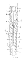
【図5】上記の実施形態における光コネクタの詳細構造を説明する横断面図である。
【図6】上記の実施形態における光コネクタの詳細構造を説明する縦断面図である。
【図7】本発明の他の実施形態における熱収縮チューブ部近傍を示した図である。
【図8】従来の光コネクタの光ファイバコード取付方法又は構造を説明する図である。
【図9】図8における要部を示した斜視図である。
【符号の説明】
1 フェルール
2 メカニカルスプライス
3 光コネクタ本体部
4 ハウジング
5 光コネクタ
6 後部ハウジング
7 コイルバネ
8 ゴムブーツ
10 内蔵光ファイバ
11、11A 光ファイバコード
11a 光ファイバ
11b 被覆チューブ
13 保護チューブ
15、15A 熱収縮チューブ
15a 端部大径部[0001]
TECHNICAL FIELD OF THE INVENTION
BACKGROUND OF THE
[0002]
[Prior art]
As shown in FIGS. 8 and 9, an
[0003]
When the
[0004]
When the
[0005]
[Problems to be solved by the invention]
In the above-mentioned optical fiber cord attaching operation, the protective tape processing for winding the
SUMMARY OF THE INVENTION The present invention has been made to solve the above-mentioned conventional drawbacks, and it is complicated to attach the optical fiber to an optical connector in a state where the optical fiber exposed from the coating tube of the optical fiber cord is covered with the protective tube. Provided is an optical fiber cord capable of protecting an optical fiber exposed portion satisfactorily and efficiently without using an inadequate protective tape treatment, and an optical fiber cord processing method when an optical connector is attached. The purpose is to:
[0006]
[Means for Solving the Problems]
The invention of
One end of the heat-shrinkable tube is placed over the end of the coating tube and tightly fixed by heating, and the rear end of the protective tube is inserted into the other end of the heat-shrinkable tube.
[0007]
The invention according to
One end of the heat-shrinkable tube is covered over the entire end portions of the plurality of coated tubes and tightly fixed by heating, and the rear end of the protective tube is inserted into the other end of the heat-shrinkable tube. .
[0008]
In advance, one end of the heat-shrinkable tube is put on the end of the coating tube and fixed tightly by heating, and the rear end of the protective tube is inserted into the other end of the heat-shrinkable tube. After attaching the optical fiber to the optical connector, the protective tube is slid toward the optical connector, and the entire optical fiber exposed from the covering tube is covered with the protective tube and the heat shrinkable tube.
[0009]
Claim 4 is a method of processing an optical fiber cord at the time of mounting an optical connector in a case where a protective tube is covered over a plurality of optical fibers exposed from each coating tube in a plurality of optical fiber cords,
In advance, one end of the heat-shrinkable tube is put over the entire ends of the plurality of coated tubes and tightly fixed by heating, and the rear end of the protective tube is inserted into the other end of the heat-shrinkable tube. After attaching the optical fibers of the plurality of optical fiber cords to the multi-core optical connector, the protective tube is slid to the optical connector side, and the entire optical fiber exposed from the covering tube is covered with the protective tube and the heat shrink tube. It is characterized by covering.
[0010]
A fifth aspect of the present invention is characterized in that, in the third or fourth aspect, after the protective tube is slid toward the optical connector, the protective tube is fixed to the heat-shrinkable tube and / or the optical connector with an adhesive tape.
[0011]
According to a sixth aspect of the present invention, there is provided the optical connector according to the fourth aspect, wherein the optical connector main body in which the multi-pin ferrule of the fitting pin alignment method and the mechanical splice are integrated is housed in a housing. The optical connector is characterized in that:
[0012]
A seventh aspect of the present invention is characterized in that the heat-shrinkable tube according to the second aspect has a stepped shape in which a diameter of a portion covering the entire end portion of the plurality of coating tubes is larger than a diameter of a portion into which the protective tube is inserted. I do.
[0013]
BEST MODE FOR CARRYING OUT THE INVENTION
FIG. 1 is a diagram illustrating an
In these figures, an
Further, the
[0014]
The operation of attaching the
In a factory, the heat-
That is, first, as shown in FIG. 2A, each of the
Next, as shown in FIG. 2 (b), the stepped heat-
Next, the
[0015]
The operation of attaching the
As shown in FIG. 3C, the
Next, as shown in FIG. 3D, two optical connector parts are put on the two
Next, as shown in FIG. 4E, the built-in
Next, as shown in FIG. 4F, the optical connector
Next, as shown in FIG. 4G, the
Next, the front end and / or the rear end of the
Thus, the attachment of the
[0016]
With the
[0017]
The detailed structure of the
[0018]
When the optical connector
[0019]
In the above embodiment, two single-core
Further, as shown in FIG. 7, two or more
[0020]
Further, the optical fiber cord of the embodiment has a structure in which the
The optical connector according to the embodiment has a structure in which an optical connector main body in which a ferrule of a fitting pin positioning method and a mechanical splice are integrated is housed in a housing, but the size of the ferrule is not particularly limited. Therefore, the ferrule may be for a small MT connector or a normal MT optical connector, and may be applied to an optical connector called an MT-RJ connector, an MPO optical connector, or the like.
Further, the optical connector targeted by the present invention is not limited to the one integrated with the ferrule and the mechanical splice, but may be a simple single-core optical connector (for example, SC optical connector (JIS C5973-F04 type single-core optical fiber connector)). .
[0021]
【The invention's effect】
According to the present invention, for example, one end of the heat-shrinkable tube is put on the end of the coated tube in advance at the factory, and is tightly fixed by heating, and the rear end of the protective tube is attached to the other end of the heat-shrinkable tube. In the work of attaching the optical connector to the optical connector, after attaching the optical fiber of the optical fiber cord to the optical connector, slide the protective tube toward the optical connector to remove the entire optical fiber exposed from the sheath tube. , Can be covered and protected with a protective tube and a heat shrink tube. Therefore, the optical fiber exposed from the covering tube can be protected sufficiently sufficiently as compared with the conventional method having the protective tape processing section. In addition, on-site work is simplified, and workability is improved.
[Brief description of the drawings]
FIG. 1 is a diagram illustrating an optical fiber cord attaching method or structure of an optical connector according to an embodiment of the present invention.
FIG. 2 is a view for explaining operations performed in advance in a factory among procedures of an optical fiber cord attaching method for an optical connector according to an embodiment of the present invention.
FIG. 3 is a diagram illustrating the first half of a field work for attaching an optical connector to a field after the factory work in FIG. 2;
FIG. 4 is a diagram illustrating the latter half of the on-site work following FIG. 3;
FIG. 5 is a cross-sectional view illustrating a detailed structure of the optical connector in the embodiment.
FIG. 6 is a longitudinal sectional view illustrating a detailed structure of an optical connector in the embodiment.
FIG. 7 is a view showing the vicinity of a heat-shrinkable tube in another embodiment of the present invention.
FIG. 8 is a diagram illustrating a method or structure for attaching an optical fiber cord to a conventional optical connector.
FIG. 9 is a perspective view showing a main part in FIG. 8;
[Explanation of symbols]
DESCRIPTION OF
Claims (7)
前記被覆チューブの端部に熱収縮チューブの一端側を被せかつ加熱により密着固定し、この熱収縮チューブの他端側に前記保護チューブの後端側を挿入したことを特徴とする光ファイバコード。An optical fiber cord in which a protective tube is covered on the optical fiber exposed from the coated tube,
An optical fiber cord, wherein one end of a heat-shrinkable tube is placed over the end of the covering tube and is fixedly adhered by heating, and the rear end of the protective tube is inserted into the other end of the heat-shrinkable tube.
前記複数本の被覆チューブの端部全体に熱収縮チューブの一端側を被せかつ加熱により密着固定し、この熱収縮チューブの他端側に前記保護チューブの後端側を挿入したことを特徴とする光ファイバコード。An optical fiber cord in which a protective tube is covered over a plurality of optical fibers exposed from each coating tube in the plurality of optical fiber cords,
One end of the heat-shrinkable tube is covered over the entire end portions of the plurality of coated tubes and tightly fixed by heating, and the rear end of the protective tube is inserted into the other end of the heat-shrinkable tube. Optical fiber cord.
予め、前記被覆チューブの端部に熱収縮チューブの一端側を被せかつ加熱により密着固定し、かつ、保護チューブの後端側を前記熱収縮チューブの他端側に挿入しておき、光ファイバコードの光ファイバを光コネクタに取り付けた後、保護チューブを光コネクタ側にスライドさせて、被覆チューブから露出させた光ファイバの全体を保護チューブおよび熱収縮チューブで覆うことを特徴とする光コネクタ取付時の光ファイバコード処理方法。An optical fiber cord processing method at the time of mounting an optical connector when a protective tube is put on an optical fiber exposed from a coating tube of an optical fiber cord,
In advance, one end of the heat-shrinkable tube is put on the end of the coating tube and fixed tightly by heating, and the rear end of the protective tube is inserted into the other end of the heat-shrinkable tube. After attaching the optical fiber to the optical connector, slide the protective tube toward the optical connector, and cover the entire optical fiber exposed from the coated tube with the protective tube and the heat-shrinkable tube. Optical fiber cord processing method.
予め、前記複数本の被覆チューブの端部全体に熱収縮チューブの一端側を被せかつ加熱により密着固定し、かつ、保護チューブの後端側を前記熱収縮チューブの他端側に挿入しておき、複数本の光ファイバコードの光ファイバを多心の光コネクタに取り付けた後、保護チューブを光コネクタ側にスライドさせて、被覆チューブから露出させた光ファイバの全体を保護チューブおよび熱収縮チューブで覆うことを特徴とする光コネクタ取付時の光ファイバコード処理方法。An optical fiber cord processing method at the time of mounting an optical connector when a protective tube is covered over a plurality of optical fibers exposed from each coating tube in a plurality of optical fiber cords,
In advance, one end of the heat-shrinkable tube is put over the entire ends of the plurality of coated tubes and tightly fixed by heating, and the rear end of the protective tube is inserted into the other end of the heat-shrinkable tube. After attaching the optical fibers of the plurality of optical fiber cords to the multi-core optical connector, the protective tube is slid to the optical connector side, and the entire optical fiber exposed from the covering tube is covered with the protective tube and the heat shrink tube. An optical fiber cord processing method for mounting an optical connector, characterized by covering.
Priority Applications (1)
| Application Number | Priority Date | Filing Date | Title |
|---|---|---|---|
| JP2002305042A JP3960545B2 (en) | 2002-10-18 | 2002-10-18 | Optical fiber cord processing method for optical connector mounting |
Applications Claiming Priority (1)
| Application Number | Priority Date | Filing Date | Title |
|---|---|---|---|
| JP2002305042A JP3960545B2 (en) | 2002-10-18 | 2002-10-18 | Optical fiber cord processing method for optical connector mounting |
Publications (2)
| Publication Number | Publication Date |
|---|---|
| JP2004138917A true JP2004138917A (en) | 2004-05-13 |
| JP3960545B2 JP3960545B2 (en) | 2007-08-15 |
Family
ID=32452287
Family Applications (1)
| Application Number | Title | Priority Date | Filing Date |
|---|---|---|---|
| JP2002305042A Expired - Fee Related JP3960545B2 (en) | 2002-10-18 | 2002-10-18 | Optical fiber cord processing method for optical connector mounting |
Country Status (1)
| Country | Link |
|---|---|
| JP (1) | JP3960545B2 (en) |
Cited By (7)
| Publication number | Priority date | Publication date | Assignee | Title |
|---|---|---|---|---|
| JP2006126376A (en) * | 2004-10-27 | 2006-05-18 | Tomoegawa Paper Co Ltd | Optical fiber structure, fan-out optical fiber structure using the same, and manufacturing method thereof |
| JP2008089703A (en) * | 2006-09-29 | 2008-04-17 | Furukawa Electric Co Ltd:The | Optical connector mounting method to optical fiber core, optical connector assembly, optical fiber core protective tube, and temporary core fixing tool used therefor |
| WO2011087077A1 (en) * | 2010-01-14 | 2011-07-21 | 株式会社フジクラ | Optical connector and ferrule for optical connector |
| KR101167344B1 (en) | 2004-08-20 | 2012-07-19 | 니폰 덴신 덴와 가부시끼가이샤 | Optical connector and method of assembling optical connector |
| KR20150111475A (en) * | 2014-03-25 | 2015-10-06 | 엘에스전선 주식회사 | Optical Fiber Jumper Cord |
| US9927583B2 (en) | 2010-01-14 | 2018-03-27 | Fujikura Ltd. | Optical connector and optical connector ferrule |
| JP2024035601A (en) * | 2022-09-02 | 2024-03-14 | 古河電気工業株式会社 | Multi-core optical fiber cord with optical components, manufacturing method of multi-core optical fiber cord with optical components |
-
2002
- 2002-10-18 JP JP2002305042A patent/JP3960545B2/en not_active Expired - Fee Related
Cited By (10)
| Publication number | Priority date | Publication date | Assignee | Title |
|---|---|---|---|---|
| KR101167344B1 (en) | 2004-08-20 | 2012-07-19 | 니폰 덴신 덴와 가부시끼가이샤 | Optical connector and method of assembling optical connector |
| US8297850B2 (en) | 2004-08-20 | 2012-10-30 | Sumitomo Electric Industries, Ltd. | Optical connector, and method of assembling optical connector |
| JP2006126376A (en) * | 2004-10-27 | 2006-05-18 | Tomoegawa Paper Co Ltd | Optical fiber structure, fan-out optical fiber structure using the same, and manufacturing method thereof |
| JP2008089703A (en) * | 2006-09-29 | 2008-04-17 | Furukawa Electric Co Ltd:The | Optical connector mounting method to optical fiber core, optical connector assembly, optical fiber core protective tube, and temporary core fixing tool used therefor |
| WO2011087077A1 (en) * | 2010-01-14 | 2011-07-21 | 株式会社フジクラ | Optical connector and ferrule for optical connector |
| JP5400155B2 (en) * | 2010-01-14 | 2014-01-29 | 株式会社フジクラ | Optical connector and ferrule for optical connector |
| US9927583B2 (en) | 2010-01-14 | 2018-03-27 | Fujikura Ltd. | Optical connector and optical connector ferrule |
| KR20150111475A (en) * | 2014-03-25 | 2015-10-06 | 엘에스전선 주식회사 | Optical Fiber Jumper Cord |
| KR102139386B1 (en) * | 2014-03-25 | 2020-07-30 | 엘에스전선 주식회사 | Optical Fiber Jumper Cord |
| JP2024035601A (en) * | 2022-09-02 | 2024-03-14 | 古河電気工業株式会社 | Multi-core optical fiber cord with optical components, manufacturing method of multi-core optical fiber cord with optical components |
Also Published As
| Publication number | Publication date |
|---|---|
| JP3960545B2 (en) | 2007-08-15 |
Similar Documents
| Publication | Publication Date | Title |
|---|---|---|
| EP2664952B1 (en) | Optical connector and method for assembling same | |
| JP5481576B2 (en) | Optical connector, pin clamp, and optical connector assembly method | |
| CN100533191C (en) | Optical connector and method of assembling optical connector | |
| EP2193395B1 (en) | Strain-relief assemblies and methods for a field-installable fiber optic connector | |
| WO2008059842A1 (en) | Optical connector | |
| CA2718432A1 (en) | Fusion-splice fiber optic connectors and related tools | |
| JP2002082257A (en) | Optical connectors and optical connector parts | |
| CA2692809A1 (en) | Fusion-splice fiber optic connectors and related tools | |
| JP2004138917A (en) | Optical fiber cord and optical fiber cord processing method when optical connector is attached | |
| WO2005001533A1 (en) | Method of assembling optical fiber conector | |
| JP3988655B2 (en) | Connection structure between metal connector type optical fiber cable with tensile strength fiber and optical connector | |
| JP7443540B2 (en) | Optical connector and optical connector manufacturing method | |
| US20120045184A1 (en) | Installation assembly for splicing optical fibers and method for splicing optical fibers | |
| JP7421974B2 (en) | Metal tube coated optical fiber cable with optical connector, manufacturing method of metal tube coated optical fiber cable with optical connector | |
| JP4155153B2 (en) | Optical fiber connecting member and optical fiber connecting method | |
| US6939056B2 (en) | Anchor for fiber optic cable | |
| JP4928220B2 (en) | Optical fiber pseudo-code terminal processing structure, pseudo-code holding body, and simple optical fiber connection terminal processing structure | |
| WO2025204090A1 (en) | Optical connector and method for attaching optical connector | |
| RU2395107C2 (en) | Opticl connector for terminating optical fibre, distribution point having said connector, device for terminating optical fibre and method to this end | |
| JP3773978B2 (en) | Multi-fiber single-fiber conversion optical fiber with optical fiber connector | |
| JP2000314824A (en) | Optical connector | |
| JPH11352358A (en) | Optical connector manufacturing method and optical connector ferrule | |
| CN119816765A (en) | Outdoor field assembly optical connector | |
| JP2005043634A (en) | Termination parts with optical connectors, outlets for optical connectors | |
| JP2009271427A (en) | Optical connector |
Legal Events
| Date | Code | Title | Description |
|---|---|---|---|
| A621 | Written request for application examination |
Free format text: JAPANESE INTERMEDIATE CODE: A621 Effective date: 20050606 |
|
| A977 | Report on retrieval |
Free format text: JAPANESE INTERMEDIATE CODE: A971007 Effective date: 20070129 |
|
| A131 | Notification of reasons for refusal |
Free format text: JAPANESE INTERMEDIATE CODE: A131 Effective date: 20070213 |
|
| A521 | Request for written amendment filed |
Free format text: JAPANESE INTERMEDIATE CODE: A523 Effective date: 20070416 |
|
| TRDD | Decision of grant or rejection written | ||
| A01 | Written decision to grant a patent or to grant a registration (utility model) |
Free format text: JAPANESE INTERMEDIATE CODE: A01 Effective date: 20070511 |
|
| A61 | First payment of annual fees (during grant procedure) |
Free format text: JAPANESE INTERMEDIATE CODE: A61 Effective date: 20070511 |
|
| LAPS | Cancellation because of no payment of annual fees |