JP2004139902A - Liquid fuel cell - Google Patents
Liquid fuel cell Download PDFInfo
- Publication number
- JP2004139902A JP2004139902A JP2002304959A JP2002304959A JP2004139902A JP 2004139902 A JP2004139902 A JP 2004139902A JP 2002304959 A JP2002304959 A JP 2002304959A JP 2002304959 A JP2002304959 A JP 2002304959A JP 2004139902 A JP2004139902 A JP 2004139902A
- Authority
- JP
- Japan
- Prior art keywords
- negative electrode
- liquid fuel
- fuel cell
- electrode
- binder
- Prior art date
- Legal status (The legal status is an assumption and is not a legal conclusion. Google has not performed a legal analysis and makes no representation as to the accuracy of the status listed.)
- Pending
Links
Images

Classifications
-
- Y—GENERAL TAGGING OF NEW TECHNOLOGICAL DEVELOPMENTS; GENERAL TAGGING OF CROSS-SECTIONAL TECHNOLOGIES SPANNING OVER SEVERAL SECTIONS OF THE IPC; TECHNICAL SUBJECTS COVERED BY FORMER USPC CROSS-REFERENCE ART COLLECTIONS [XRACs] AND DIGESTS
- Y02—TECHNOLOGIES OR APPLICATIONS FOR MITIGATION OR ADAPTATION AGAINST CLIMATE CHANGE
- Y02E—REDUCTION OF GREENHOUSE GAS [GHG] EMISSIONS, RELATED TO ENERGY GENERATION, TRANSMISSION OR DISTRIBUTION
- Y02E60/00—Enabling technologies; Technologies with a potential or indirect contribution to GHG emissions mitigation
- Y02E60/30—Hydrogen technology
- Y02E60/50—Fuel cells
Landscapes
- Fuel Cell (AREA)
- Inert Electrodes (AREA)
Abstract
【課題】液体燃料の酸化反応がスムーズに進行する負極を含む液体燃料電池を提供する。
【解決手段】酸素を還元する正極8と、燃料を酸化する負極9と、正極8と負極9との間に設けられた電解質層10とを含む液体燃料電池であって、負極9がイオン伝導性を持たない非フッ素系のバインダを含み、前記バインダが、例えば、ポリエチレン、ポリプロピレン、ナイロン、ポリエステル、アイオノマー、ブチルゴム、エチレン・酢酸ビニル共重合体、エチレン・エチルアクリレート共重合体およびエチレン・アクリル酸共重合体からなる群から選択される少なくとも一つを含む液体燃料電池とする。
【選択図】 図1Provided is a liquid fuel cell including a negative electrode in which an oxidation reaction of a liquid fuel proceeds smoothly.
A liquid fuel cell includes a positive electrode for reducing oxygen, a negative electrode for oxidizing a fuel, and an electrolyte layer provided between the positive electrode and the negative electrode, wherein the negative electrode is an ion conductive material. A non-fluorinated binder having no property, wherein the binder is, for example, polyethylene, polypropylene, nylon, polyester, ionomer, butyl rubber, ethylene / vinyl acetate copolymer, ethylene / ethyl acrylate copolymer, and ethylene / acrylic acid The liquid fuel cell includes at least one selected from the group consisting of copolymers.
[Selection diagram] Fig. 1
Description
【0001】
【発明の属する技術分野】
本発明は、燃料として液体を用いた液体燃料電池に関する。
【0002】
【従来の技術】
近年、パソコン、携帯電話などのコードレス機器の普及に伴い、その電源である二次電池はますます小型化、高容量化が要望されている。現在、エネルギー密度が高く、小型軽量化が図れる二次電池としてリチウムイオン二次電池が実用化されており、ポータブル電源として需要が増大している。しかし、使用されるコードレス機器の種類によっては、このリチウム二次電池では未だ十分な連続使用時間を保証する程度までには至っていない。
【0003】
このような状況の中で上記要望に応え得る電池として、燃料電池が期待されている。中でも、液体燃料を直接電池の反応に利用する直接メタノール型燃料電池は、小型化が可能であり、将来のポータブル電源として有望である(例えば、特許文献1参照。)。
【0004】
この直接メタノール型燃料電池の電極は、正極および負極ともにカーボン粉末上に貴金属粒子を高分散した触媒、プロトン交換樹脂およびポリテトラフルオロエチレン(PTFE)から構成されている。このPTFEをバインダとして使用することで一定の強度を有する電極を形成できるとともに、電極に撥水性を付与することができる(例えば、非特許文献1参照。)。
【0005】
【特許文献1】
特開2000−268836号公報
【0006】
【非特許文献1】
コーデェッシュ(Kordesch)、外2名、「イーシーエス プロシーディングズ(ECS Proceedings)」、(米国)、1982年、第82−2巻、第265号、p.427−428
【0007】
【発明が解決しようとする課題】
上記直接メタノール型燃料電池の正極では、気体である酸素が反応するため、この反応を阻害する水分を除去する必要から撥水性が要求される。一方、負極では液体であるメタノールが反応するため、逆に撥水性があると電極の濡れ性が悪くなりメタノールの酸化反応が進みにくくなる問題がある。しかし、従来の直接メタノール型燃料電池では、正極および負極ともにバインダとしてPTFEを含んでいたため撥水性を有しており、負極としては必ずしも最適な構成ではなかった。
【0008】
ここで、親水性のバインダを上記負極に用いることも考えられるが、従来の親水性バインダはイオン伝導性を有するため、これを直接メタノール型燃料電池に使用すると、燃料のメタノールによりバインダが膨潤、溶解するという問題があった。
【0009】
本発明は、液体燃料の酸化反応がスムーズに進行する負極を含む液体燃料電池を提供するものである。
【0010】
【課題を解決するための手段】
本発明の液体燃料電池は、酸素を還元する正極と、燃料を酸化する負極と、前記正極と前記負極との間に設けられた電解質層とを含む液体燃料電池であって、前記負極が、イオン伝導性を持たない非フッ素系のバインダを含むことを特徴とする。
【0011】
【発明の実施の形態】
以下、本発明の実施の形態を説明する。
【0012】
本発明の液体燃料電池の一実施形態は、酸素を還元する正極と、燃料を酸化する負極と、前記正極と前記負極との間に設けられた電解質層とを含む液体燃料電池であり、前記負極が、イオン伝導性を持たない非フッ素系のバインダを含むものである。
【0013】
非フッ素系のバインダを使用することにより、撥水性を付与することなく負極を形成することが可能となり、負極と液体燃料との濡れ性が向上し、電極特性が良好となる。また、イオン伝導性を持たないバインダを使用することにより、液体燃料によりバインダが膨潤、溶解することがない。
【0014】
イオン伝導性を持たない非フッ素系のバインダとしては種々のものが使用できるが、熱可塑性であることが好ましい。電極の製作が容易になるからである。熱可塑性のバインダとしては、ポリエチレン、ポリプロピレン、ナイロン、ポリエステル、アイオノマー、ブチルゴム、エチレン・酢酸ビニル共重合体、エチレン・エチルアクリレート共重合体およびエチレン・アクリル酸共重合体からなる群から選択される少なくとも一つを含むことが好ましい。
【0015】
ただし、イオン伝導性を持たない非フッ素系のバインダとして熱硬化性樹脂も使用可能である。例えば、エポキシ樹脂、キシレン樹脂、ジアリルフタレート樹脂、不飽和ポリエステル樹脂、フェノール樹脂などである。
【0016】
また、イオン伝導性を持たない非フッ素系のバインダの粒子径は、0.01〜100μmであることが好ましい。この範囲内であれば、十分な結着性が得られ、またバインダ自体が嵩高くならず、触媒中に均一に分散できるからである。
【0017】
また、本実施形態の液体燃料電池は、正極と、負極と、電解質層とが、電極・電解質一体化物を形成し、複数の電極・電解質一体化物が同一平面上に配置されていることが好ましい。電池の厚さを薄くすることが可能となるからである。
【0018】
負極は、例えば、多孔性の炭素材料からなる拡散層と、触媒を担持した炭素粉末、プロトン導電性物質およびイオン伝導性を持たない非フッ素系のバインダからなる触媒層とを積層して構成される。
【0019】
負極はメタノールを酸化する機能を有しており、その触媒には、例えば、白金微粒子や、鉄、ニッケル、コバルト、錫、ルテニウムまたは金などと白金との合金微粒子などが用いられるが、これらに限定されるものではない。
【0020】
触媒の担体である炭素粉末は、例えばBET比表面積が10〜2000m2/gのカーボンブラックが用いられる。この炭素粉末に前記触媒を例えばコロイド法を用いて担持する。炭素粉末と触媒の質量比は、炭素粉末100質量部に対し、触媒を5質量部〜400質量部とすることが好ましい。この範囲内であれば、十分な触媒活性が得られ、また触媒の粒子径が大きくなりすぎず、触媒活性が低下しないからである。
【0021】
プロトン導電性物質としては、例えば、ポリパーフルオロスルホン酸樹脂、スルホン化ポリエーテルスルホン酸樹脂、スルホン化ポリイミド樹脂などのスルホン酸基を有する樹脂を用いることができるが、これらに限定されるものではない。このようなプロトン導電性物質の含有量は、触媒担持炭素粉末100質量部に対し、2質量部〜200質量部とすることが好ましい。この範囲内であれば、十分なプロトン伝導性が得られ、また電気抵抗が大きくならず、電池性能が低下しないからである。
【0022】
また、イオン伝導性を持たない非フッ素系のバインダの含有量は、触媒担持炭素粉末100質量部に対し、0.01質量部〜100質量部とすることが好ましい。この範囲内であれば、十分な結着性が得られ、また電気抵抗が大きくならず、電池性能が低下しないからである。
【0023】
以上の材料を用いた負極の製造方法について説明する。先ず、前記触媒を担持した炭素粉末、プロトン導電性物質、イオン伝導性を持たない非フッ素系のバインダと水と有機溶剤とを均一に分散してスラリーとする。このスラリーの固形分量は、スラリーの全質量100質量部に対して1〜70質量部が好ましい。1質量部未満では十分な粘性が得られないため作業性が悪く、70質量部を超えると粘性が高くなりすぎて作業性が悪くなるからである。これらの材料の分散は、例えばボールミル、ホモジナイザー、超音波分散機などを用いて行なうことができるが、これらに限定されない。また、上記有機溶剤としては、例えば、メタノール、エタノール、プロパノール、ブタノールなどが使用できる。
【0024】
その後、上記で得られたスラリーを、多孔性の炭素材料からなる拡散層に塗布して乾燥する。続いて熱プレスを行なうことで、バインダが溶融結着し、負極が形成される。熱プレスの温度は、バインダの種類によって異なるが、使用するバインダのガラス転移点以上、ガラス転移点を20℃上回る温度以下に設定することが好ましい。プレスの圧力は3〜50MPaが好ましい。3MPa未満では電極の成形が十分でなく、50MPaを超えると電極内のポアがつぶれてしまい、電池性能が低下するからである。
【0025】
次に、前記電解質層について説明する。この電解質層は、電子伝導性を持たずプロトンを輸送することが可能な材料により構成される。例えば、ポリパーフルオロスルホン酸樹脂膜、具体的には、デュポン社製の“ナフィオン”(商品名)、旭硝子社製の“フレミオン”(商品名)、旭化成工業社製の“アシプレックス”(商品名)などにより電解質層を構成することができる。その他では、スルホン化ポリエーテルスルホン酸樹脂膜、スルホン化ポリイミド樹脂膜、硫酸ドープポリベンズイミダゾール膜などからも構成することができる。
【0026】
また、前記正極は、例えば、多孔性の炭素材料からなる拡散層と、触媒を担持した炭素粉末、プロトン導電性物質およびフッ素樹脂バインダからなる触媒層とを積層して構成される。正極は、酸素を還元する機能を有しており、フッ素樹脂バインダとしては、例えば、ポリテトラフルオロエチレン(PTFE)、テトラフルオロエチレン−パーフルオロアルキルビニルエーテル共重合体(PFA)、テトラフルオロエチレン−ヘキサフルオロプロピレン共重合体(FEP)、テトラフルオロエチレン−エチレン共重合体(E/TFE)、ポリビニリデンフルオライド(PVDF)およびポリクロロトリフルオロエチレン(PCTFE)などを用いることができる。このバインダの量は、触媒担持炭素粉末100質量部に対し、0.01質量部〜100質量部とすることが好ましい。0.01質量部未満では十分な結着性が得られず、100質量部を超えると電気抵抗が大きくなり、電池性能が低下するからである。バインダを除いたその他においては前記負極と同様に構成することができる。
【0027】
これらの正極および負極で電解質層を挟持し、熱プレスで圧着して電極・電解質一体化物を作製できる。熱プレスの温度は、100〜180℃に設定することが好ましい。プレスの圧力は3〜50MPaが好ましい。100℃未満、3MPa未満では電極の形成が十分でなく、180℃および50MPaを超えると電極内のポアがつぶれてしまい、電池性能が低下するからである。
【0028】
このようにして作製した電極・電解質一体化物は、負極に撥水性バインダを含有していないため、負極の液体燃料に対する濡れ性に優れ、液体燃料の酸化反応がスムーズに進行するため、電池性能の向上を図ることができる。また、負極のバインダは、イオン伝導性を持たないため、液体燃料によりバインダが膨潤、溶解することがない。
【0029】
次に、本発明の実施の形態を図面に基づき説明する。
【0030】
図1は、本発明の一実施形態における液体燃料電池の断面図である。正極8は、例えば、多孔性の炭素材料からなる拡散層8aと、触媒を担持した炭素粉末からなる触媒層8bとを積層して構成される。
【0031】
電解質層10は、電子伝導性を持たずプロトンを輸送することが可能な前記材料により構成される。
【0032】
負極9は、拡散層9aと触媒層9bとからなり、燃料からプロトンを生成する機能、即ち燃料を酸化する機能を有しており、例えば、イオン伝導性を持たない非フッ素系のバインダを使用したこと以外は、前記正極と同様に構成することができる。
【0033】
上記正極8、上記負極9および上記電解質層10は、積層されて電極・電解質一体化物を構成している。即ち、電極・電解質一体化物は、正極8と、負極9と、正極8と負極9との間に設けられた電解質層10とから構成されている。また、前記電極・電解質一体化物は同一電池容器内の同一平面上に複数個備えられている。
【0034】
負極9の電解質層10と反対側には液体燃料4を貯蔵する燃料タンク3が隣接して設けられている。液体燃料4としては、例えば、メタノール水溶液、エタノール水溶液、ジメチルエーテル、水素化ホウ素ナトリウム水溶液、水素化ホウ素カリウム水溶液、水素化ホウ素リチウム水溶液などが用いられる。燃料タンク3は、例えば、PTFE、硬質ポリ塩化ビニル、ポリプロピレン、ポリエチレンなどの樹脂や、ステンレス鋼などの耐食性金属から構成されている。ただし、燃料タンク3を金属で構成する際には、同一電池容器内に配置されているそれぞれの負極同士が電気的に短絡しないように絶縁体を導入する必要がある。燃料タンク3の負極9と接する部分には燃料供給孔3aが設けられており、この部分から液体燃料4が負極9へと供給される。また、液体燃料を含浸して保持し且つ負極9に液体燃料を供給する燃料吸い上げ材5が、負極9と接する個所を含む燃料タンク3の内部に設けられている。これにより、液体燃料4が消費されても、液体燃料4と負極9との接触が維持されるため、液体燃料4を最後まで使い切ることができる。燃料吸い上げ材5としては、ガラス繊維を用いることができるが、燃料の含浸によって寸法が余り変化せず、化学的にも安定なものであれば他の材料を用いてもよい。
【0035】
正極8の電解質層10と反対側にはカバー板2が設けられており、カバー板2の正極8と接する部分には空気孔1が設けられている。これにより、空気孔1を通して大気中の酸素が正極8と接することになる。カバー板2の端部には、カバー板2と燃料タンク3を貫通する構造を持つ気液分離孔兼燃料充填口6bが設けられている。この気液分離孔兼燃料充填口6bの燃料タンク3と反対側には脱着可能な気液分離膜6aが設けられている。この気液分離膜6aは細孔を持つPTFE製シートからなり、放電反応で生成した二酸化炭素などを、燃料を漏液させることなく燃料タンク3から放出させることができる。また、気液分離膜6aを脱着可能とすることで、燃料を補充する時の充填口ともなる。気液分離孔兼燃料充填口6b、カバー板2および空気孔1は、例えば、燃料タンク3と同様の材料から構成されている。
【0036】
正極8の電解質層10と反対側の、正極8と接する箇所から、隣接する電極・電解質一体化物の負極9の電解質層10と反対側の、負極9と接する箇所に渡って集電体7が設置されており、正極8と隣接する電極・電解質一体化物の負極9は電気的に接続されている。集電体7は隣接する電極・電解質一体化物を電気的に直列に接続する役割を持ち、同一電池容器内に並べられた全ての電極・電解質一体化物は集電体7によって電気的に直列に接続される。集電体7は、例えば、白金、金などの貴金属や、ステンレス鋼などの耐食性金属、またはカーボンなどから構成されている。
【0037】
【実施例】
次に、本発明の液体燃料電池を実施例に基づき具体的に説明する。ただし、本発明は以下の実施例に限定されるものではない。
【0038】
(実施例1)
以下のようにして、図1と同様の構造の液体燃料電池を作製した。
【0039】
正極は以下のようにして作製した。先ず、ライオンアクゾ社製の“ケッチェンブラックEC”(商品名)を50質量部、平均粒子径3nmの白金微粒子を50質量部担持した白金担持カーボンを10質量部、エレクトロケミ(Electrochem)社製のプロトン導電性物質“ナフィオン(Nafion)”(商品名、固形分濃度5質量%)を75質量部、バインダとしてダイキン社製のポリテトラフルオロエチレンエマルジョン溶液“D1”(商品名、エマルジョン濃度60質量%)を10質量部および水を5質量部準備した。これらをホモジナイザーで混合分散し、拡散層であるカーボンクロスに白金量が8mg/cm2になるように塗布して乾燥した。次に、120℃、10MPaの条件で2分間熱プレスを行ない電極として成型し、正極を得た。
【0040】
負極は以下のように作製した。先ず、前記“ケッチェンブラックEC”を50質量部、平均粒子径3nmの白金ルテニウム合金(合金比1:1)微粒子を50質量部担持した白金担持カーボンを10質量部、前記“ナフィオン”を75質量部、バインダとして平均分子量15000で平均粒子径1μmのポリエチレン粉末を5質量部および水を10質量部準備した。これらをホモジナイザーで均一に混合分散し、拡散層であるカーボンクロスに白金量が8mg/cm2になるように塗布して乾燥した。次に、120℃、10MPaの条件で2分間熱プレスを行ない電極として成型し、負極を得た。
【0041】
電解質層は、デュポン社製の“ナフィオン117”(商品名)を用い、正極および負極でこの電解質層を挟持し、120℃、10MPaの条件で3分間熱プレスを行ない、電極・電解質一体化物を作製した。なお、電極面積は正極、負極ともに10cm2とした。
【0042】
正極の電解質層と反対側に設けられているカバー板および燃料タンクは、ステンレス(SUS316)に絶縁性の塗膜として日本ペイント社製のフェノール樹脂系塗料“マイカスA”(商品名)を塗布したもので構成した。正極集電体は厚さ10μmの金製のシートからなり、エポキシ樹脂を用いて正極と接着した。液体燃料としては、5質量%のメタノール水溶液を用いた。負極集電体は正極集電体と同様の材質で構成した。気液分離膜は細孔を持つPTFE製の膜から構成した。
【0043】
(実施例2)
負極のバインダとして前記ポリエチレン粉末5質量部に代えて、平均粒子径1μmのエチレン・エチルアクリレート共重合体粉末5質量部を用い、プレス時の加熱温度を160℃としたこと以外は、実施例1と同様にして液体燃料電池を作製した。
【0044】
(比較例1)
負極の材料である前記ポリエチレン粉末5質量部と水10質量部に代えて、前記ポリテトラフルオロエチレンエマルジョン溶液“D1”10質量部と水5質量部を用い、プレス時の加熱温度を160℃としたこと以外は、実施例1と同様にして液体燃料電池を作製した。
【0045】
以上のように作製した実施例1、実施例2および比較例1の液体燃料電池に対して、室温下で500mAを印加したときの作動電圧を測定した。その結果を表1に示す。
【0046】
【表1】
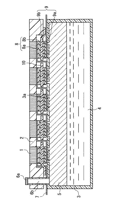
表1から明らかなように、実施例1および実施例2では、比較例1に比べて作動電圧が高いことが分かる。これは、実施例1および実施例2ではメタノール水溶液に対する負極の濡れ性が大きいため、メタノールの酸化反応が進み、負極性能が向上したものと考えられる。
【0048】
【発明の効果】
以上説明したように本発明の液体燃料電池は、撥水性を付与することなく負極を形成することが可能となり、優れた性能の液体燃料電池を提供することができる。
【図面の簡単な説明】
【図1】本発明の一実施形態における液体燃料電池の断面図である。
【符号の説明】
1 空気孔
2 カバー板
3 燃料タンク
3a 燃料供給孔
4 液体燃料
5 燃料吸い上げ材
6a 気液分離膜
6b 気液分離孔兼燃料充填口
7 集電体
8 正極
8a 拡散層
8b 触媒層
9 負極
9a 拡散層
9b 触媒層
10 電解質層[0001]
TECHNICAL FIELD OF THE INVENTION
The present invention relates to a liquid fuel cell using a liquid as fuel.
[0002]
[Prior art]
2. Description of the Related Art In recent years, with the spread of cordless devices such as personal computers and mobile phones, there is a demand for smaller and higher capacity secondary batteries as power sources. At present, lithium ion secondary batteries have been put to practical use as secondary batteries having a high energy density and can be reduced in size and weight, and demand for portable power sources is increasing. However, depending on the type of cordless device used, this lithium secondary battery has not yet reached a level where sufficient continuous use time is guaranteed.
[0003]
In such a situation, a fuel cell is expected as a battery that can meet the above demand. Above all, a direct methanol fuel cell using a liquid fuel for the reaction of the cell can be downsized and is promising as a portable power source in the future (for example, see Patent Document 1).
[0004]
The electrode of this direct methanol fuel cell is composed of a catalyst in which noble metal particles are highly dispersed on carbon powder, a proton exchange resin, and polytetrafluoroethylene (PTFE) for both the positive electrode and the negative electrode. By using this PTFE as a binder, it is possible to form an electrode having a certain strength and to impart water repellency to the electrode (for example, see Non-Patent Document 1).
[0005]
[Patent Document 1]
JP 2000-268836 A
[Non-patent document 1]
Kodesch, two others, "ECS Proceedings", (USA), 1982, Vol. 82-2, No. 265, p. 427-428
[0007]
[Problems to be solved by the invention]
In the positive electrode of the direct methanol fuel cell, gaseous oxygen reacts. Therefore, water repellency is required because it is necessary to remove water that hinders the reaction. On the other hand, since the liquid methanol reacts on the negative electrode, conversely, if there is water repellency, there is a problem that the wettability of the electrode deteriorates and the oxidation reaction of methanol becomes difficult to proceed. However, in the conventional direct methanol fuel cell, both the positive electrode and the negative electrode have PTFE as a binder and thus have water repellency, so that the structure of the negative electrode is not always optimal.
[0008]
Here, it is conceivable to use a hydrophilic binder for the negative electrode.However, since a conventional hydrophilic binder has ionic conductivity, when this is directly used for a methanol-type fuel cell, the binder swells due to methanol of the fuel, There was a problem of dissolution.
[0009]
The present invention provides a liquid fuel cell including a negative electrode in which an oxidation reaction of a liquid fuel proceeds smoothly.
[0010]
[Means for Solving the Problems]
A liquid fuel cell of the present invention is a liquid fuel cell including a positive electrode for reducing oxygen, a negative electrode for oxidizing fuel, and an electrolyte layer provided between the positive electrode and the negative electrode, wherein the negative electrode is It is characterized by containing a non-fluorine-based binder having no ion conductivity.
[0011]
BEST MODE FOR CARRYING OUT THE INVENTION
Hereinafter, embodiments of the present invention will be described.
[0012]
One embodiment of the liquid fuel cell of the present invention is a liquid fuel cell including a positive electrode for reducing oxygen, a negative electrode for oxidizing fuel, and an electrolyte layer provided between the positive electrode and the negative electrode. The negative electrode contains a non-fluorinated binder having no ion conductivity.
[0013]
By using a non-fluorine-based binder, the negative electrode can be formed without imparting water repellency, the wettability between the negative electrode and the liquid fuel is improved, and the electrode characteristics are improved. In addition, by using a binder having no ion conductivity, the binder does not swell or dissolve due to the liquid fuel.
[0014]
Various non-fluorine-based binders having no ion conductivity can be used, but are preferably thermoplastic. This is because the production of the electrode becomes easy. As the thermoplastic binder, at least one selected from the group consisting of polyethylene, polypropylene, nylon, polyester, ionomer, butyl rubber, ethylene / vinyl acetate copolymer, ethylene / ethyl acrylate copolymer and ethylene / acrylic acid copolymer Preferably one is included.
[0015]
However, a thermosetting resin can also be used as a non-fluorinated binder having no ion conductivity. For example, epoxy resin, xylene resin, diallyl phthalate resin, unsaturated polyester resin, phenol resin and the like.
[0016]
Further, the particle diameter of the non-fluorinated binder having no ion conductivity is preferably 0.01 to 100 μm. Within this range, sufficient binding properties can be obtained, and the binder itself does not become bulky and can be uniformly dispersed in the catalyst.
[0017]
Further, in the liquid fuel cell according to the present embodiment, it is preferable that the positive electrode, the negative electrode, and the electrolyte layer form an electrode-electrolyte integrated body, and the plurality of electrode-electrolyte integrated bodies are arranged on the same plane. . This is because the thickness of the battery can be reduced.
[0018]
The negative electrode is formed by, for example, laminating a diffusion layer made of a porous carbon material and a catalyst layer made of a carbon powder carrying a catalyst, a proton conductive substance and a non-fluorine-based binder having no ionic conductivity. You.
[0019]
The negative electrode has a function of oxidizing methanol.For the catalyst, for example, platinum fine particles, alloy fine particles of platinum such as iron, nickel, cobalt, tin, ruthenium or gold, and the like are used. It is not limited.
[0020]
As the carbon powder as a carrier of the catalyst, for example, carbon black having a BET specific surface area of 10 to 2000 m 2 / g is used. The catalyst is supported on the carbon powder by using, for example, a colloid method. The mass ratio of the carbon powder to the catalyst is preferably 5 parts by mass to 400 parts by mass with respect to 100 parts by mass of the carbon powder. Within this range, a sufficient catalytic activity can be obtained, and the particle size of the catalyst does not become too large and the catalytic activity does not decrease.
[0021]
As the proton conductive substance, for example, a resin having a sulfonic acid group such as a polyperfluorosulfonic acid resin, a sulfonated polyethersulfonic acid resin, and a sulfonated polyimide resin can be used, but is not limited thereto. Absent. The content of such a proton conductive substance is preferably 2 parts by mass to 200 parts by mass with respect to 100 parts by mass of the catalyst-supporting carbon powder. Within this range, sufficient proton conductivity can be obtained, the electrical resistance does not increase, and the battery performance does not decrease.
[0022]
The content of the non-fluorinated binder having no ion conductivity is preferably 0.01 to 100 parts by mass based on 100 parts by mass of the catalyst-supporting carbon powder. Within this range, sufficient binding properties can be obtained, electric resistance does not increase, and battery performance does not decrease.
[0023]
A method for manufacturing a negative electrode using the above materials will be described. First, a carbon powder carrying the catalyst, a proton conductive substance, a non-fluorinated binder having no ion conductivity, water and an organic solvent are uniformly dispersed to form a slurry. The solid content of the slurry is preferably from 1 to 70 parts by mass based on 100 parts by mass of the total mass of the slurry. If the amount is less than 1 part by mass, sufficient viscosity cannot be obtained, resulting in poor workability. If the amount exceeds 70 parts by mass, the viscosity becomes too high and the workability deteriorates. Dispersion of these materials can be performed using, for example, a ball mill, a homogenizer, an ultrasonic disperser, or the like, but is not limited thereto. Further, as the organic solvent, for example, methanol, ethanol, propanol, butanol and the like can be used.
[0024]
Thereafter, the slurry obtained above is applied to a diffusion layer made of a porous carbon material and dried. Subsequently, by performing hot pressing, the binder is melt-bound and a negative electrode is formed. The temperature of the hot press varies depending on the type of the binder, but is preferably set to a temperature equal to or higher than the glass transition point of the binder to be used and equal to or lower than 20 ° C. higher than the glass transition point. The pressure of the press is preferably 3 to 50 MPa. If the pressure is less than 3 MPa, the electrode is not formed sufficiently. If the pressure exceeds 50 MPa, the pores in the electrode are crushed, and the battery performance is reduced.
[0025]
Next, the electrolyte layer will be described. This electrolyte layer is made of a material having no electron conductivity and capable of transporting protons. For example, polyperfluorosulfonic acid resin membranes, specifically, "Nafion" (trade name) manufactured by DuPont, "Flemion" (trade name) manufactured by Asahi Glass Co., Ltd., "Aciplex" (trade name) manufactured by Asahi Kasei Corporation ) Can constitute the electrolyte layer. In addition, it can be constituted by a sulfonated polyether sulfonic acid resin film, a sulfonated polyimide resin film, a sulfuric acid-doped polybenzimidazole film, or the like.
[0026]
Further, the positive electrode is formed by, for example, laminating a diffusion layer made of a porous carbon material and a catalyst layer made of a carbon powder carrying a catalyst, a proton conductive substance and a fluororesin binder. The positive electrode has a function of reducing oxygen, and examples of the fluororesin binder include polytetrafluoroethylene (PTFE), tetrafluoroethylene-perfluoroalkylvinyl ether copolymer (PFA), and tetrafluoroethylene-hexa. For example, fluoropropylene copolymer (FEP), tetrafluoroethylene-ethylene copolymer (E / TFE), polyvinylidene fluoride (PVDF), and polychlorotrifluoroethylene (PCTFE) can be used. The amount of the binder is preferably 0.01 to 100 parts by mass based on 100 parts by mass of the catalyst-supporting carbon powder. If the amount is less than 0.01 part by mass, a sufficient binding property cannot be obtained, and if the amount exceeds 100 parts by mass, the electric resistance increases and the battery performance deteriorates. Except for the binder, the structure can be the same as that of the negative electrode.
[0027]
An electrolyte layer is sandwiched between the positive electrode and the negative electrode, and pressed by a hot press to produce an integrated electrode / electrolyte product. The temperature of the hot press is preferably set to 100 to 180 ° C. The pressure of the press is preferably 3 to 50 MPa. If the temperature is lower than 100 ° C. and lower than 3 MPa, the formation of the electrode is not sufficient.
[0028]
Since the electrode / electrolyte integrated body thus produced does not contain a water-repellent binder in the negative electrode, it has excellent wettability to the liquid fuel of the negative electrode, and the oxidation reaction of the liquid fuel proceeds smoothly. Improvement can be achieved. Further, since the binder of the negative electrode has no ionic conductivity, the binder does not swell or dissolve by the liquid fuel.
[0029]
Next, an embodiment of the present invention will be described with reference to the drawings.
[0030]
FIG. 1 is a sectional view of a liquid fuel cell according to one embodiment of the present invention. The
[0031]
The
[0032]
The
[0033]
The
[0034]
A
[0035]
A
[0036]
The current collector 7 extends from a portion of the
[0037]
【Example】
Next, the liquid fuel cell of the present invention will be specifically described based on examples. However, the present invention is not limited to the following examples.
[0038]
(Example 1)
A liquid fuel cell having the same structure as in FIG. 1 was manufactured as follows.
[0039]
The positive electrode was produced as follows. First, 50 parts by mass of “Ketjen Black EC” (trade name) manufactured by Lion Akzo Co., and 10 parts by mass of platinum-supporting carbon supporting 50 parts by mass of platinum fine particles having an average particle diameter of 3 nm were manufactured by Electrochem. 75 parts by mass of a proton conductive substance “Nafion” (trade name, solid content concentration: 5% by mass), and a polytetrafluoroethylene emulsion solution “D1” (trade name, emulsion concentration of 60 parts by Daikin) as a binder %) And 5 parts by mass of water. These were mixed and dispersed with a homogenizer, applied to a carbon cloth as a diffusion layer so that the amount of platinum became 8 mg / cm 2 , and dried. Next, hot pressing was performed at 120 ° C. and 10 MPa for 2 minutes to form an electrode, thereby obtaining a positive electrode.
[0040]
The negative electrode was manufactured as follows. First, 50 parts by mass of “Ketjen Black EC”, 10 parts by mass of platinum-supported carbon carrying 50 parts by mass of platinum-ruthenium alloy (alloy ratio 1: 1) fine particles having an average particle diameter of 3 nm, and 75 parts by mass of “Nafion” 5 parts by mass of polyethylene powder having an average molecular weight of 15000 and an average particle diameter of 1 μm as a binder, and 10 parts by mass of water were prepared. These were uniformly mixed and dispersed with a homogenizer, applied to a carbon cloth as a diffusion layer so that the amount of platinum was 8 mg / cm 2 , and dried. Next, hot pressing was performed for 2 minutes at 120 ° C. and 10 MPa to form an electrode to obtain a negative electrode.
[0041]
For the electrolyte layer, “Nafion 117” (trade name) manufactured by DuPont was used. The electrolyte layer was sandwiched between the positive electrode and the negative electrode. Produced. The electrode area was 10 cm 2 for both the positive electrode and the negative electrode.
[0042]
The cover plate and the fuel tank provided on the side opposite to the electrolyte layer of the positive electrode were coated with stainless steel (SUS316) and a phenolic resin paint “Mykas A” (trade name) manufactured by Nippon Paint Co., Ltd. as an insulating coating film. Made up of things. The positive electrode current collector was made of a gold sheet having a thickness of 10 μm, and was bonded to the positive electrode using an epoxy resin. As the liquid fuel, a 5% by mass aqueous methanol solution was used. The negative electrode current collector was made of the same material as the positive electrode current collector. The gas-liquid separation membrane was composed of a PTFE membrane having pores.
[0043]
(Example 2)
Example 1 was repeated except that 5 parts by mass of the ethylene / ethyl acrylate copolymer powder having an average particle diameter of 1 μm was used as the binder for the negative electrode instead of 5 parts by mass of the polyethylene powder, and the heating temperature during pressing was 160 ° C. A liquid fuel cell was produced in the same manner as described above.
[0044]
(Comparative Example 1)
Instead of 5 parts by mass of the polyethylene powder and 10 parts by mass of water, which are materials of the negative electrode, 10 parts by mass of the polytetrafluoroethylene emulsion solution “D1” and 5 parts by mass of water were used, and the heating temperature during pressing was 160 ° C. A liquid fuel cell was manufactured in the same manner as in Example 1 except for the above.
[0045]
The operating voltage when 500 mA was applied at room temperature to the liquid fuel cells of Example 1, Example 2, and Comparative Example 1 manufactured as described above was measured. Table 1 shows the results.
[0046]
[Table 1]
As is clear from Table 1, it is understood that the working voltage is higher in Examples 1 and 2 than in Comparative Example 1. This is considered to be because in Examples 1 and 2, the wettability of the negative electrode with respect to the methanol aqueous solution was large, so that the oxidation reaction of methanol proceeded and the negative electrode performance was improved.
[0048]
【The invention's effect】
As described above, the liquid fuel cell of the present invention can form a negative electrode without imparting water repellency, and can provide a liquid fuel cell having excellent performance.
[Brief description of the drawings]
FIG. 1 is a sectional view of a liquid fuel cell according to an embodiment of the present invention.
[Explanation of symbols]
Reference Signs List 1
Claims (5)
前記負極が、イオン伝導性を持たない非フッ素系のバインダを含むことを特徴とする液体燃料電池。A liquid fuel cell including a positive electrode for reducing oxygen, a negative electrode for oxidizing fuel, and an electrolyte layer provided between the positive electrode and the negative electrode,
A liquid fuel cell, wherein the negative electrode includes a non-fluorine-based binder having no ion conductivity.
Priority Applications (1)
| Application Number | Priority Date | Filing Date | Title |
|---|---|---|---|
| JP2002304959A JP2004139902A (en) | 2002-10-18 | 2002-10-18 | Liquid fuel cell |
Applications Claiming Priority (1)
| Application Number | Priority Date | Filing Date | Title |
|---|---|---|---|
| JP2002304959A JP2004139902A (en) | 2002-10-18 | 2002-10-18 | Liquid fuel cell |
Publications (1)
| Publication Number | Publication Date |
|---|---|
| JP2004139902A true JP2004139902A (en) | 2004-05-13 |
Family
ID=32452225
Family Applications (1)
| Application Number | Title | Priority Date | Filing Date |
|---|---|---|---|
| JP2002304959A Pending JP2004139902A (en) | 2002-10-18 | 2002-10-18 | Liquid fuel cell |
Country Status (1)
| Country | Link |
|---|---|
| JP (1) | JP2004139902A (en) |
Cited By (2)
| Publication number | Priority date | Publication date | Assignee | Title |
|---|---|---|---|---|
| WO2006092914A1 (en) * | 2005-02-28 | 2006-09-08 | Toagosei Co., Ltd. | Membrane electrode joined product, process for producing the same, and direct methanol-type fuel cell |
| JP2006344530A (en) * | 2005-06-09 | 2006-12-21 | Toyota Motor Corp | Catalyst electrode layer, membrane electrode composite, and production method thereof |
-
2002
- 2002-10-18 JP JP2002304959A patent/JP2004139902A/en active Pending
Cited By (3)
| Publication number | Priority date | Publication date | Assignee | Title |
|---|---|---|---|---|
| WO2006092914A1 (en) * | 2005-02-28 | 2006-09-08 | Toagosei Co., Ltd. | Membrane electrode joined product, process for producing the same, and direct methanol-type fuel cell |
| JPWO2006092914A1 (en) * | 2005-02-28 | 2008-08-07 | 東亞合成株式会社 | Membrane electrode assembly, method for producing the same, and direct methanol fuel cell |
| JP2006344530A (en) * | 2005-06-09 | 2006-12-21 | Toyota Motor Corp | Catalyst electrode layer, membrane electrode composite, and production method thereof |
Similar Documents
| Publication | Publication Date | Title |
|---|---|---|
| CN100350659C (en) | Power generating element for liquid fuel cell, method for producing the same, and liquid fuel cell using the same | |
| CN102195046B (en) | For the membrane-electrode assembly of fuel cell, its method for making and fuel cell system | |
| JP2009059524A (en) | Gas diffusion layer for fuel cell, method for producing the same, and fuel cell | |
| JP4190478B2 (en) | Polymer electrolyte fuel cell | |
| JP4137660B2 (en) | Liquid fuel cell | |
| JP2008311180A (en) | Membrane electrode assembly, method for producing the same, and fuel cell using the membrane electrode assembly | |
| JP2004171844A (en) | Liquid fuel cell | |
| WO2003069709A1 (en) | Liquid fuel cell | |
| KR101561101B1 (en) | Polymer catalyst Slurry composition, porous electrodes produced thereby, membrane-electrode assembly comprising the porous electrodes, and method for the MEA | |
| JP2007214102A (en) | Membrane electrode assembly, method for producing membrane electrode assembly, and fuel cell | |
| CN100508266C (en) | Membrane electrode unit | |
| EP2202830A1 (en) | Membrane electrode assembly and fuel cell | |
| JP4180556B2 (en) | Polymer electrolyte fuel cell | |
| JP2005353541A (en) | Power generation element for liquid fuel cell, method for manufacturing the same, and liquid fuel cell | |
| JP4236156B2 (en) | Fuel cell | |
| JP4872202B2 (en) | Fuel cell and fuel cell manufacturing method | |
| US20100221625A1 (en) | Low-porosity anode diffusion media for high concentration direct methanol fuel cells and method of making | |
| JP2004139902A (en) | Liquid fuel cell | |
| KR101112693B1 (en) | Membrane Electrode Assembly for Fuel Cell and Manufacturing Method Thereof | |
| JP4828864B2 (en) | Gas diffusion electrode for polymer electrolyte fuel cell, membrane-electrode assembly for polymer electrolyte fuel cell, production method thereof, and polymer electrolyte fuel cell | |
| JP2006032163A (en) | Power generation element for liquid fuel cell and liquid fuel cell using the same | |
| JP2007134306A (en) | Direct oxidation fuel cell and membrane electrode assembly thereof | |
| JP2006107877A (en) | Power generation element for liquid fuel cell, method for manufacturing the same, and liquid fuel cell | |
| JP2004247226A (en) | Liquid fuel cell | |
| JP2005259646A (en) | Power generation element for liquid fuel cell and liquid fuel cell using the same |
Legal Events
| Date | Code | Title | Description |
|---|---|---|---|
| A621 | Written request for application examination |
Free format text: JAPANESE INTERMEDIATE CODE: A621 Effective date: 20050418 |
|
| A977 | Report on retrieval |
Free format text: JAPANESE INTERMEDIATE CODE: A971007 Effective date: 20070921 |
|
| A131 | Notification of reasons for refusal |
Free format text: JAPANESE INTERMEDIATE CODE: A131 Effective date: 20070927 |
|
| A02 | Decision of refusal |
Free format text: JAPANESE INTERMEDIATE CODE: A02 Effective date: 20080214 |