JP2004147902A - Suturing prosthesis aid - Google Patents
Suturing prosthesis aid Download PDFInfo
- Publication number
- JP2004147902A JP2004147902A JP2002317141A JP2002317141A JP2004147902A JP 2004147902 A JP2004147902 A JP 2004147902A JP 2002317141 A JP2002317141 A JP 2002317141A JP 2002317141 A JP2002317141 A JP 2002317141A JP 2004147902 A JP2004147902 A JP 2004147902A
- Authority
- JP
- Japan
- Prior art keywords
- cloth
- suture
- absorbent material
- body made
- biodegradable absorbent
- Prior art date
- Legal status (The legal status is an assumption and is not a legal conclusion. Google has not performed a legal analysis and makes no representation as to the accuracy of the status listed.)
- Granted
Links
- 239000000463 material Substances 0.000 claims abstract description 55
- 238000009958 sewing Methods 0.000 claims abstract description 34
- 239000004744 fabric Substances 0.000 claims abstract description 32
- 230000002745 absorbent Effects 0.000 claims description 26
- 239000002250 absorbent Substances 0.000 claims description 26
- AEMRFAOFKBGASW-UHFFFAOYSA-N Glycolic acid Chemical compound OCC(O)=O AEMRFAOFKBGASW-UHFFFAOYSA-N 0.000 claims description 8
- JVTAAEKCZFNVCJ-UHFFFAOYSA-N lactic acid Chemical compound CC(O)C(O)=O JVTAAEKCZFNVCJ-UHFFFAOYSA-N 0.000 claims description 8
- 238000005304 joining Methods 0.000 claims description 7
- 239000000853 adhesive Substances 0.000 claims description 6
- 230000001070 adhesive effect Effects 0.000 claims description 6
- 229920001577 copolymer Polymers 0.000 claims description 6
- 235000014655 lactic acid Nutrition 0.000 claims description 4
- 239000004310 lactic acid Substances 0.000 claims description 4
- 239000002759 woven fabric Substances 0.000 claims description 4
- PAPBSGBWRJIAAV-UHFFFAOYSA-N ε-Caprolactone Chemical compound O=C1CCCCCO1 PAPBSGBWRJIAAV-UHFFFAOYSA-N 0.000 claims description 4
- 229920000954 Polyglycolide Polymers 0.000 claims description 3
- 239000004633 polyglycolic acid Substances 0.000 claims description 3
- 229920000747 poly(lactic acid) Polymers 0.000 claims description 2
- 239000004626 polylactic acid Substances 0.000 claims description 2
- 239000002023 wood Substances 0.000 claims 1
- 238000001356 surgical procedure Methods 0.000 abstract description 3
- 238000001727 in vivo Methods 0.000 abstract 2
- 239000004753 textile Substances 0.000 abstract 1
- 238000005520 cutting process Methods 0.000 description 33
- 239000004745 nonwoven fabric Substances 0.000 description 32
- 230000003014 reinforcing effect Effects 0.000 description 10
- 210000001519 tissue Anatomy 0.000 description 6
- 230000002093 peripheral effect Effects 0.000 description 5
- 230000000694 effects Effects 0.000 description 4
- 229920002635 polyurethane Polymers 0.000 description 4
- 239000004814 polyurethane Substances 0.000 description 4
- 239000000155 melt Substances 0.000 description 3
- 239000004677 Nylon Substances 0.000 description 2
- 230000003902 lesion Effects 0.000 description 2
- 229920001778 nylon Polymers 0.000 description 2
- 238000006116 polymerization reaction Methods 0.000 description 2
- -1 polyparadioxanone Substances 0.000 description 2
- 210000004872 soft tissue Anatomy 0.000 description 2
- 229920002101 Chitin Polymers 0.000 description 1
- 230000015572 biosynthetic process Effects 0.000 description 1
- 239000008280 blood Substances 0.000 description 1
- 210000004369 blood Anatomy 0.000 description 1
- 238000007664 blowing Methods 0.000 description 1
- 230000008602 contraction Effects 0.000 description 1
- 229920001971 elastomer Polymers 0.000 description 1
- 239000010408 film Substances 0.000 description 1
- 230000004927 fusion Effects 0.000 description 1
- 238000009940 knitting Methods 0.000 description 1
- 210000004072 lung Anatomy 0.000 description 1
- 239000012567 medical material Substances 0.000 description 1
- 238000000034 method Methods 0.000 description 1
- 239000000203 mixture Substances 0.000 description 1
- 229920001610 polycaprolactone Polymers 0.000 description 1
- 239000004632 polycaprolactone Substances 0.000 description 1
- 238000003825 pressing Methods 0.000 description 1
- 238000004080 punching Methods 0.000 description 1
- 239000000126 substance Substances 0.000 description 1
- 230000000451 tissue damage Effects 0.000 description 1
- 231100000827 tissue damage Toxicity 0.000 description 1
Images


Landscapes
- Surgical Instruments (AREA)
- Materials For Medical Uses (AREA)
Abstract
Description
【0001】
【産業上の利用分野】
本発明は、外科手術等における自動縫合器に用いて好適な縫合補綴材の提供に関する。
【0002】
【従来の技術】
従来、多数のステープルを埋入したホッチキスタイプの自動縫合器は組織の切除等に多用されるが、肺等への適用においては縫合部からの空気漏れの問題、また、軟弱組織への適用においては組織の損傷、断裂等の問題を生じることがあった。かかる問題に対して、本出願人は先に、ステープル部に装着して使用する筒状の縫合補綴材について提案した。(特許文献1、2参照)
【0003】
【特許文献1】
実用新案登録第2604025号公報
【特許文献2】
特許第3136392号公報
【0004】
上記の公知例において、例えば生体内分解吸収性素材よりなる長方形状の不織布を筒状に形成する際、耳端部を粗く仮縫いして筒状体に形成するとか、或いは生体内分解吸収性素材よりなる長方形状の不織布とポリウレタン弾性糸にナイロン糸をカバリングした糸使いにより編成した長方形状の伸縮性編地であるパワーネット生地の両者を組み合わせて筒状に形成する際、その耳端部をぐし縫い(粗縫い)して筒状体に形成し、次いでこれらの筒状体を自動縫合器に装着し、手術時に一対の筒状に形成した不織布間で又は不織布と伸縮性編物地で筒状体に形成したものにおいて一対の不織布間で保持された人体組織に対し、ステープルの締金操作並びにカッター操作を行って病変部と正常組織部分に分断し、更に仮縫い又はぐし縫いを施した縫着部の縫糸端を引っ張ることにより、前記筒状体が正常組織部側に残存する不織布部分と病変部側に連結された伸縮性編物等の部分とに分断され、病変部側はパワーネット生地等と共に対外に撤去される旨の内容が記載されている。
また、切断を容易にするためのミシン目を中央部に設けた構成も示される。
【0005】
【発明が解決しようとする課題】
しかしながら上記のように仮縫い又はぐし縫いを施した縫着部の縫糸端を引っ張って正常組織部側に残存する不織布部分と病変部側に連結された状態の伸縮性編物等の部分とに分断するにあたり、スムーズに糸が抜けなかったり、それによって組織を傷つけたりする等の問題が生じる恐れがあった。
【0006】
【課題を解決するための手段】
本発明は、上記のような課題を解決するために生体内分解吸収性素材よりなる長方形状の布状体に予め一対のミシン目状引き裂き用切断部を設けると共に、同布状体の耳端部を縫着などの手段により筒状体に形成し、手術時に縫糸端の延出部を引っ張ることにより、前記の引き裂き用切断部の分断が容易に行われる構成としたことに特徴を有するものである。
即ち、該構成により縫合器によるファイアーカット後、ステープルライン補強部位とそれ以外の部分との分断操作が容易且つ正確に行えるものである。
【0007】
また、別の構成として、上記のように予め一対のミシン目状引き裂き用切断部を設けた生体内分解吸収性素材による長方形状の布状体とは別に伸縮性編織物地による長方形状の布状体を準備し、両者の耳端部を縫着などの手段を介して筒状体に形成することにより、高価な生体内分解吸収性素材の使用量を少量とし、生体内分解吸収性素材自身のもつ伸縮性と伸縮性編織物地素材のもつ伸縮性によって自動縫合器への装着性をより改善し、位置ずれすることがなく、生地の伸縮性による緊張状態により、より安価により切断性を高めたものである。
【0008】
【発明の実施の形態】
生体内分解吸収性素材よりなる長方形状の布状体に一対のミシン目状引き裂き用切断部を設ける場合、その切断部の切断方向は、筒状体の切断方向と同一方向に連続し、端部から端部にわたって設ける。或いは、筒状体の外周面上において湾曲状を描くように設けてもよい。
なお、該引き裂き用ミシン目は、例えば、凸部を切断歯、凹部を溝としたカッター等を用い、これを押圧することにより形成することができる。ミシン目のピッチ、大きさは特に限定しないが、歯長と溝長が比較的短いピッチの細かいもの、歯長が長く溝長の短いものは引き裂き性に優れる。しかしながら、ミシン目の作成位置によって引き裂き性が異なるので、ミシン目サイズ、ピッチは適宜選択する。
また、かかるミシン目は、引き裂きやすいようパラレルに1対設ける事を原則とするが、必要に応じて更に増やすこともできる。
【0009】
生体内分解吸収性素材による布状体としては、ポリグリコール酸、ポリ乳酸、グリコール酸と乳酸の共重合体、乳酸とカプロラクトンの共重合体、グリコール酸とカプロラクトンの共重合体あるいはそれらの混合物、更にはポリパラジオキサノン、ポリカプロラクトン、キチン等、既に医用材料として適用されている素材の編地、織地、不織布、フィルム、シート、スポンジシート等を例示できるが、特に柔軟性、通気性、腰、厚さ、吸血性、ステープルライン形成性、加水分解性等の面より、ポリグリコール酸を素材とした不織布が好適な素材として例示できる。なお、かかる不織布は、ニードルパンチ、メルトブロー等、公知の方法によって製造されたもので、特に不織布単独で筒状の縫合補綴材を提供する場合は、自動縫合器への装着性を損なわないようある程度の伸縮性を有するものが好ましい。かかる生体内分解吸収性素材は、そのまま体内に放置して異物として残留しない特徴を有する。
【0010】
引き裂き用切断部を設けた生体内分解吸収性素材による布状体と組み合わせて筒状体を形成するようにした伸縮性を有する編織物地としては、その編織物地の生地組織の中に、例えばゴム糸、ポリウレタン系弾性糸、捲縮性加工糸、嵩高加工糸等が適宜交編、交織されており、縦、横方向に伸縮性を有するものが好ましく、またその組織については特に限定しないが、裁断作業や、筒状体形成時の縫製作業等の容易性、更に形態安定性等の面から例えばポリウレタン糸にナイロン糸をカバリングして得た伸縮性糸を用いて経編地に編成したパワーネット生地が特に好適な例として例示できる。
【0011】
生体内分解吸収性素材からなる長方形状の布状体を用いて筒状体を形成する場合は、縫合器の外周サイズに合わせて裁断された1枚の生地を丸めて筒状にする場合と、2枚の生地を重ねあわせ、両端を接合する場合がある。かかる接合は、縫製、溶融接着、接着剤等任意の手段によって行われ、端部を重ね合わせるときは、平坦状に重合する場合と、手合わせ状に重合する場合がある。縫製によってこれを接合する場合は、縫着部前後の縫糸端は、ミシン目状引き裂き用切断部を引き裂いて分断するための引き裂き用糸として、適宜の長さに延出しておくのが望ましい。この場合、1枚の生地にて筒状を構成する場合、1対のミシン目は、該縫合部の両端に位置するよう配置する必要がある。縫合作業が完了し、ファイアーカットが行われた後において、かかる糸端を上方に引っ張ることにより、また、両端を縫合し、筒状にした場合、一対の引き裂き用糸を同時に把持して上方へ引っ張ることにより、ミシン目状引き裂き用切断部が、順次引き裂かれていき、分断されるのである。
なお、筒状体を形成する際、溶融接着又は接着剤によって形成する場合は、引き裂き用糸として溶融接着、接着剤部の前或いは後端部に適宜の長さのコード糸を接着するか、又は筒状体の廃棄、撤去用周面部の外表面上に適宜の長さのコード糸を溶融接着又は接着剤等の手段によって接着しておくことが望ましい。
縫製による縫糸、融着接着、接着剤により一体化するコード糸は、非分解性、分解性を問わず任意であるが、かかる操作に耐え得る強度を有することが望まれる。
また、その糸端はループ上につながっていてもよい。
【0012】
本発明による縫合補綴材が適用される開胸用の自動縫合器としては、U.S.SURGICAL社製のマルチファイヤーGIA80、マルチファイヤーGIA60、GIA50P、GIA90P、エチコン社製のプロキシメイトリニアカッター55mm及び75mm等が例示できる。また胸腔鏡用の自動縫合器としては、U.S.SURGICAL社製のエンドGIA▲2▼30、エンドGIA▲2▼45、エンドGIA▲2▼60、エチコン社製のエンドパスエンドカッターETS45、EZ45等が例示できる。これらの縫合器への適用に際してはステープル内臓のカートリッジ部とステープル受け溝を有するアンビル部に被包させるという簡単な操作によって行うことができる。
【0013】
以下、本発明による縫合補綴材の実施例について図面をもとに説明するが本発明はこれに限定されない。
【実施例1】
図1は本発明における実施例1による縫合補綴材10を示したもので、生体内分解吸収性素材からなる長方形状の不織布11を丸めて筒状体12を形成し、且つ両耳端部を平らに重合した状態で同重合部13を手縫いにより、ぐし縫い14(波縫い、粗縫い)を施してあり、且つその縫糸の両端部をそれぞれ延出して縫糸延長部15、16を形成してある。17,17は夫々筒状の不織布11に予め設けたミシン目状の引き裂き用切断部で、筒状体12の軸方向と平行状で且つ直線状に形成してある。自動縫合器に前記縫合補綴材10を装着してファイアーカットした後、一対の縫糸延長部15或いは16を手作業で上方に引っ張り上げることにより、引き裂き用切断部17,17が同時に引き裂かれ、ステープルライン補強部位として残る部分(下側部分)と除去する部分(縫糸を含む上部)の分断を容易に行うことができる。
【0014】
【実施例2】
図2は本発明における実施例2による縫合補綴材20を示したもので、生体内分解吸収性素材からなる長方形状の不織布21を丸めて筒状体22を形成し、且つ両側縁部を手合わせ状に重合した状態で同重合部23に対して手縫いにより、縫製24を施してあり、且つその縫糸の両端部をそれぞれ延出して縫糸延長部25、26を形成してある。27,27は夫々筒状の不織布21に予め設けたミシン目状の引き裂き用切断部で、筒状体22の軸方向と平行状で且つ直線状に形成してある。尚、自動縫合器に前記縫合補綴材20を装着してファイアーカットした後、一対の縫糸延長部25或いは26を夫々手作業で引っ張って持ち上げることにより、引き裂き用切断部27,27が同時に引き裂かれ、ステープルライン補強部位(下側部分)とそれ以外の除去される部分(縫糸を含む上部)の分断を容易に行うことができる。
【0015】
【実施例3】
図3は本発明における実施例3による縫合補綴材30を示したもので、生体内分解吸収性素材からなる長方形状の不織布31を丸めて筒状体32を形成し、且つ両側縁部を手合わせ状に重合した状態で同重合部33に対して手縫いにより、ぐし縫い35を施してあり、且つその縫糸の両端部をそれぞれ延出して縫糸延長部36、37を形成してある。38,38は夫々筒状の不織布31に対して予め設けたミシン目状の引き裂き用切断部で、筒状体32の外周面上で湾曲状に形成してある。尚、図示略の自動縫合器に縫合補綴材30を装着してファイアーカットした後、一対の縫糸延長部35或いは36を夫々手作業で引っ張って持ち上げることにより、引き裂き用切断部38、38が同時に引き裂かれ、ステープルライン補強部位(下側部分)とそれ以外の除去される部分(縫糸を含む上部)の分断を容易に行うことができる。
【0016】
【実施例4】
図4は本発明における実施例4による縫合補綴材40を示したもので、生体内分解吸収性素材からなる長方形状の不織布41を丸めて筒状体42を形成し、且つ両耳端部を平らに重合した状態で同重合部43に対して通常のミシンにより、縫着45を施してあり、且つそのミシン糸の両端部をそれぞれ延出して下糸及び上糸による縫糸延長部46、46、47、47夫々2本を形成してある。48,48は夫々筒状の不織布41に対して予め設けたミシン目状の引き裂き用切断部で、筒状体42の軸方向と平行状で且つ直線状に形成してある。尚、図示略の自動縫合器に縫合補綴材40を装着してファイアーカットした後、一対の縫糸延長部46或いは47を夫々手作業で引っ張って持ち上げることにより、引き裂き用切断部48、48が同時に引き裂かれ、ステープルライン補強部位(下側部分)とそれ以外の除去される部分(縫糸を含む上部)の分断を容易に行うことができる。
【0017】
【実施例5】
図5は本発明における実施例5による縫合補綴材50を示したもので、生体内分解吸収性素材からなる長方形状の不織布51を丸めて筒状体52を形成し、且つ両耳端部を平らに重合した状態で同重合部53に対してヒータ等を押圧して溶融接着55を施してあり、且つその溶融接着部55の両端部に適宜長さのコード糸を溶融接着して引っ張り用糸56、57を夫々形成してある。58,58は夫々筒状の不織布51に対して予め設けたミシン目状の引き裂き用切断部で、筒状体52の軸方向と平行状で且つ直線状に形成してある。尚、図示略の自動縫合器に上記縫合補綴材50を装着してファイアーカットした後、一対の引っ張り用糸56、57を夫々手作業で引っ張って持ち上げることにより、引き裂き用切断部58、58が同時に引き裂かれ、ステープルライン補強部位(下側部分)とそれ以外の除去される部分(縫糸を含む上部)の分断を容易に行うことができる。
【0018】
【実施例6】
図6は本発明における実施例6による縫合補綴材60を示したもので、縦方向の長さが同一で、且つ幅方向の長さが大である長方形状の生体内分解吸収性素材による不織布61と幅方向の長さを小とした伸縮性パワーネット生地62を用いて筒状体63を形成するもので、不織布61及びパワーネット生地62の夫々の両耳端部を手合わせ状に重合した状態で同重合部64、64に対して手縫いにより、ぐし縫い65、65を夫々施して筒状体63を形成するのである。また66、67は縫糸の両端部をそれぞれ延出して形成した縫糸延長部であり、68、68は幅方向(周方向)の寸法を大とした不織布61に予め設けた一対のミシン目状引き裂き用切断部で、筒状体63の軸方向と平行状で且つ直線状に形成してある。尚、自動縫合器に前記縫合補綴材60を装着してファイアーカットした後、一対の縫糸延長部66或いは67を夫々手作業で引っ張って持ち上げることにより、引き裂き用切断部68,68が同時に引き裂かれ、ステープルライン補強部位(下側部分)とそれ以外の除去される部分(縫糸を含む上部)の分断を容易に行うことができる。
【0019】
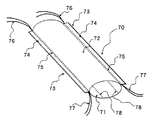
【実施例7】
図7は本発明における実施例7による縫合補綴材70を示したもので、縦方向及び幅方向の長さをほぼ同一にした長方形状の生体内分解吸収性素材による不織布71と伸縮性パワーネット生地72を介して筒状体73を形成し、且つ不織布71とパワーネット生地72の夫々の両耳端部を手合わせ状に重合した状態で同重合部74、74に対して通常のミシンにより、縫着75、75を夫々施して筒状体73を形成するのである。また76、77は夫々縫糸の両端部をそれぞれ延出して形成した縫糸延長部であり、78、78は不織布71において予め設けた一対のミシン目状引き裂き用切断部で、筒状体73の軸方向と平行状で且つ直線状に形成してある。尚、自動縫合器に前記縫合補綴材70を装着してファイアーカットした後、一対の縫糸延長部76或いは77を夫々手作業で引っ張って持ち上げることにより、引き裂き用切断部78,78が同時に引き裂かれ、ステープルライン補強部位(下側部分)とそれ以外の除去される部分(縫糸を含む上部)の分断を容易に行うことができる。
【0020】
【実施例8】
図8は本発明における実施例8による縫合補綴材80を示したもので、縦方向及び幅方向の長さをほぼ同一にした長方形状の生体内分解吸収性素材による不織布81と伸縮性パワーネット生地82を介して筒状体83を形成するもので、不織布81とパワーネット生地82の夫々の両耳端部を手合わせ状に重合した状態で同重合部84、84に対して適宜のヒータ等を押圧し、溶融接着85を施して筒状体83に形成し、更に体外に撤去される側のパワーネット生地82の外周面上に適宜長さのコード糸86を適宜に溶融接着してある。87、87は不織布81に予め設けたミシン目状引き裂き用切断部で、筒状体83の軸方向と平行状で且つ直線状に形成してある。尚、自動縫合器に上記縫合補綴材80を装着してファイアーカットした後、コード糸86を手作業で引っ張って持ち上げることにより、引き裂き用切断部87、87が同時に引き裂かれ、ステープルライン補強部位(下側部分)とそれ以外の除去される部分(縫糸を含む上部)の分断を容易に行うことができる。
【0021】
【発明の効果】
本発明は、特にステープルタイプの自動縫合器を用いた手術において切除部からの空気漏れ、或いは軟弱な組織の断裂等を防止できるという特徴ならびに材料自身が生体内分解吸収性であるため体内に長期に渡り残存しないという特徴を有すると共に、一対のミシン目状引き裂き用切断部を設けたことによってステープルライン補強部位とそれ以外との分断を容易に行える効果がある。
また比較的伸縮性のある生体内分解吸収性素材による不織布などを用いた場合は、単独の使用の場合でもその伸縮性によって自動縫合器への装着や修正操作が容易となり、また、一旦装着された後においては、その伸縮力により位置ずれすることがなく、また、ステープルにて固定した後のカッティング操作においても張力が掛かっているため、容易に切断できる効果がある。
生体内分解吸収性素材に伸縮性がない場合は、伸縮性のある素材との組み合わせにより上記と同様の装着性を得ることができカッティング操作においても容易に切断できる効果がある。
【図面の簡単な説明】
【図1】本発明の第1実施例によって得られた縫合補綴材の概略斜視図である。
【図2】本発明の第2実施例によって得られた縫合補綴材の概略斜視図である。
【図3】本発明の第3実施例によって得られた縫合補綴材の概略斜視図である。
【図4】本発明の第4実施例によって得られた縫合補綴材の概略斜視図である。
【図5】本発明の第5実施例によって得られた縫合補綴材の概略斜視図である。
【図6】本発明の第6実施例によって得られた縫合補綴材の概略斜視図である。
【図7】本発明の第7実施例によって得られた縫合補綴材の概略斜視図である。
【図8】本発明の第8実施例によって得られた縫合補綴材の概略斜視図である。
【符号の説明】
10 縫合補綴材
11 不織布
12 筒状体
13 重合部
14 ぐし縫い
15、16 縫糸延長部
17 引き裂き用切断部[0001]
[Industrial application fields]
The present invention relates to the provision of a suture prosthesis suitable for use in an automatic suturing device in a surgical operation or the like.
[0002]
[Prior art]
Conventionally, a stapler type automatic suturing device in which a large number of staples are embedded is frequently used for tissue excision, etc., but in application to the lung, etc., there is a problem of air leakage from the sutured part, and in application to soft tissue. May cause problems such as tissue damage and tearing. In response to this problem, the present applicant has previously proposed a tubular suture prosthesis material that is used by being attached to a staple portion. (See Patent Documents 1 and 2)
[0003]
[Patent Document 1]
Utility Model Registration No. 2604025 [Patent Document 2]
Japanese Patent No. 3136392 [0004]
In the above known example, for example, when a rectangular nonwoven fabric made of a biodegradable absorbent material is formed into a cylindrical shape, the ear end portion is roughly sewed to form a cylindrical body, or the biodegradable absorbent material When forming a cylindrical shape by combining both a rectangular nonwoven fabric made of polyurethane and a power net fabric, which is a rectangular stretch knitted fabric knitted by covering nylon elastic yarn with polyurethane elastic yarn, Formed into a cylindrical body by combing (rough stitching), and then mounting these cylindrical bodies on an automatic suturing device, between the nonwoven fabric formed into a pair of cylindrical shapes at the time of surgery, or with a nonwoven fabric and a stretch knitted fabric The human tissue held between a pair of non-woven fabrics formed in the shape was subjected to staple clamping operation and cutter operation to divide into the lesioned part and normal tissue part, and further subjected to temporary stitching or comb stitching By pulling the suture end of the landing part, the cylindrical body is divided into a non-woven fabric part remaining on the normal tissue part side and a stretch knitted part connected to the lesion part side, and the lesion part side is a power net fabric. The content of the removal to the outside is described.
Further, a configuration in which a perforation for facilitating cutting is provided in the central portion is also shown.
[0005]
[Problems to be solved by the invention]
However, as described above, the suture end of the sewn portion subjected to temporary stitching or comb stitching is pulled to divide into a nonwoven fabric portion remaining on the normal tissue portion side and a stretched knitted fabric portion or the like connected to the lesioned portion side. In such a case, there is a risk that the thread may not come off smoothly, and thereby the tissue may be damaged.
[0006]
[Means for Solving the Problems]
In order to solve the above-described problems, the present invention provides a pair of perforated tear cutting portions in advance in a rectangular cloth-like body made of a biodegradable absorbent material, and the ear ends of the cloth-like body. The part is formed into a cylindrical body by means such as sewing, and by pulling the extended part of the suture thread during surgery, the tearing cutting part can be easily divided. It is.
That is, with this configuration, after the fire is cut by the suturing device, the operation for dividing the staple line reinforcing portion and the other portions can be easily and accurately performed.
[0007]
In addition, as another configuration, a rectangular cloth made of a stretch knitted fabric separate from the rectangular cloth made of a biodegradable absorbent material provided with a pair of perforated tearing cutting portions in advance as described above The amount of the expensive biodegradable absorbent material is reduced to a small amount by preparing the body and forming both ear ends into a cylindrical body via means such as sewing. Due to its own elasticity and the elasticity of the elastic knitted fabric material, it improves the attachment to the automatic suturing device, does not shift, and is less expensive due to tension due to the elasticity of the fabric. It is a thing that raised.
[0008]
DETAILED DESCRIPTION OF THE INVENTION
When a pair of perforated tearing cutting parts are provided in a rectangular cloth body made of biodegradable absorbent material, the cutting direction of the cutting parts is continuous in the same direction as the cutting direction of the cylindrical body, Provided from part to end. Or you may provide so that curved shape may be drawn on the outer peripheral surface of a cylindrical body.
The tear perforation can be formed by, for example, using a cutter having a convex portion as a cutting tooth and a concave portion as a groove and pressing the cutter. The pitch and size of the perforations are not particularly limited, but fine ones having a relatively short tooth length and groove length and those having a long tooth length and a short groove length are excellent in tearability. However, the tearability varies depending on the perforation creation position, so the perforation size and pitch are selected as appropriate.
In principle, a pair of such perforations are provided in parallel to facilitate tearing, but can be further increased as necessary.
[0009]
Examples of the cloth-like body made of biodegradable absorbent material include polyglycolic acid, polylactic acid, a copolymer of glycolic acid and lactic acid, a copolymer of lactic acid and caprolactone, a copolymer of glycolic acid and caprolactone, or a mixture thereof. Further examples include knitted fabrics, woven fabrics, non-woven fabrics, films, sheets, sponge sheets and the like that have already been applied as medical materials such as polyparadioxanone, polycaprolactone, chitin, etc. In view of thickness, blood absorbency, staple line formation, hydrolyzability, and the like, a nonwoven fabric made of polyglycolic acid can be exemplified as a suitable material. Such a nonwoven fabric is manufactured by a known method such as needle punching, melt blowing, and the like, and in particular, when providing a tubular suture prosthesis material alone, the nonwoven fabric is provided to some extent so as not to impair the attachment to an automatic suturing device. What has the elasticity of these is preferable. Such a biodegradable and absorbable material has a characteristic that it is left as it is in the body and does not remain as a foreign substance.
[0010]
As a knitted fabric having elasticity that forms a cylindrical body in combination with a cloth-like body made of a biodegradable absorbent material provided with a tearing cutting part, in the fabric structure of the knitted woven fabric, For example, rubber yarns, polyurethane-based elastic yarns, crimped processed yarns, bulky processed yarns and the like are appropriately knitted and woven, and those having stretchability in the vertical and horizontal directions are preferable, and the structure is not particularly limited However, from the viewpoint of ease of cutting work, sewing work when forming a cylindrical body, and form stability, for example, knitting to warp knitted fabric using elastic yarn obtained by covering nylon yarn with polyurethane yarn, etc. The power net fabric can be exemplified as a particularly suitable example.
[0011]
When forming a cylindrical body using a rectangular cloth body made of biodegradable absorbent material, when rounding a piece of fabric cut to fit the outer peripheral size of the suturing device into a cylindrical shape There are cases where two doughs are stacked and both ends are joined. Such joining is performed by any means such as sewing, melt bonding, and adhesive. When the end portions are overlapped, they may be superposed in a flat state or superposed in a hand-to-hand manner. When these are joined by sewing, it is desirable that the ends of the suture thread before and after the sewn portion are extended to an appropriate length as a tearing thread for tearing and dividing the perforated tearing cutting portion. In this case, when a cylindrical shape is constituted by one piece of cloth, it is necessary to arrange a pair of perforations so as to be positioned at both ends of the stitched portion. After the sewing operation is completed and the fire cut is performed, by pulling the end of the thread upward, or when both ends are sewn and formed into a cylindrical shape, a pair of tearing threads are simultaneously grasped and moved upward. By pulling, the perforated tearing cutting portion is sequentially torn and divided.
When forming the cylindrical body, if it is formed by melt bonding or an adhesive, melt bonding as a tearing thread, or a cord thread of an appropriate length is bonded to the front or rear end of the adhesive part, Alternatively, it is desirable that a cord thread having an appropriate length is bonded to the outer surface of the peripheral surface portion for disposal and removal of the cylindrical body by means such as melt bonding or adhesive.
Sewing thread by sewing, fusion bonding, and cord thread integrated by an adhesive are optional regardless of non-degradability and decomposability, but it is desired to have strength that can withstand such operations.
The yarn end may be connected on the loop.
[0012]
As an automatic suture device for thoracotomy to which the suture prosthesis material according to the present invention is applied, U.S. Pat. S. Examples include Multifire GIA80, Multifire GIA60, GIA50P, GIA90P manufactured by SURGICAL, and proxy mate
[0013]
Hereinafter, although the Example of the suture prosthesis material by this invention is described based on drawing, this invention is not limited to this.
[Example 1]
FIG. 1 shows a
[0014]
[Example 2]
FIG. 2 shows a
[0015]
[Example 3]
FIG. 3 shows a
[0016]
[Example 4]
FIG. 4 shows a
[0017]
[Example 5]
FIG. 5 shows a
[0018]
[Example 6]
FIG. 6 shows a
[0019]
[Example 7]
FIG. 7 shows a
[0020]
[Example 8]
FIG. 8 shows a
[0021]
【The invention's effect】
The present invention has a feature that it can prevent air leakage from a resected part or rupture of a soft tissue, especially in an operation using a staple type automatic suturing device, and the material itself is biodegradable and absorbable for a long time. And a pair of perforated tearing cutting portions provide an effect of easily separating the staple line reinforcing portion from the rest.
In addition, when using non-woven fabric made of a relatively stretchable biodegradable and absorbable material, even when used alone, the stretchability makes it easy to attach to and repair the automatic suturing device. After that, the position does not shift due to the expansion and contraction force, and the tension is also applied in the cutting operation after fixing with the staple, so that there is an effect that it can be easily cut.
When the biodegradable absorbent material is not stretchable, the same wearability as described above can be obtained by combination with a stretchable material, and there is an effect that it can be easily cut even in a cutting operation.
[Brief description of the drawings]
FIG. 1 is a schematic perspective view of a suture prosthesis material obtained according to a first embodiment of the present invention.
FIG. 2 is a schematic perspective view of a suture prosthesis material obtained according to a second embodiment of the present invention.
FIG. 3 is a schematic perspective view of a suture prosthesis material obtained according to a third embodiment of the present invention.
FIG. 4 is a schematic perspective view of a suture prosthesis material obtained according to a fourth embodiment of the present invention.
FIG. 5 is a schematic perspective view of a suture prosthesis material obtained according to a fifth embodiment of the present invention.
FIG. 6 is a schematic perspective view of a suture prosthesis material obtained according to a sixth embodiment of the present invention.
FIG. 7 is a schematic perspective view of a suture prosthesis material obtained according to a seventh embodiment of the present invention.
FIG. 8 is a schematic perspective view of a suture prosthesis material obtained according to an eighth embodiment of the present invention.
[Explanation of symbols]
DESCRIPTION OF
Claims (7)
Priority Applications (1)
| Application Number | Priority Date | Filing Date | Title |
|---|---|---|---|
| JP2002317141A JP4409161B2 (en) | 2002-10-31 | 2002-10-31 | Suture prosthesis for automatic suturing device |
Applications Claiming Priority (1)
| Application Number | Priority Date | Filing Date | Title |
|---|---|---|---|
| JP2002317141A JP4409161B2 (en) | 2002-10-31 | 2002-10-31 | Suture prosthesis for automatic suturing device |
Publications (2)
| Publication Number | Publication Date |
|---|---|
| JP2004147902A true JP2004147902A (en) | 2004-05-27 |
| JP4409161B2 JP4409161B2 (en) | 2010-02-03 |
Family
ID=32460604
Family Applications (1)
| Application Number | Title | Priority Date | Filing Date |
|---|---|---|---|
| JP2002317141A Expired - Fee Related JP4409161B2 (en) | 2002-10-31 | 2002-10-31 | Suture prosthesis for automatic suturing device |
Country Status (1)
| Country | Link |
|---|---|
| JP (1) | JP4409161B2 (en) |
Cited By (3)
| Publication number | Priority date | Publication date | Assignee | Title |
|---|---|---|---|---|
| US8177797B2 (en) | 2003-07-17 | 2012-05-15 | Gunze Limited | Suture reinforement material for automatic suturing device |
| JP2019165847A (en) * | 2018-03-22 | 2019-10-03 | グンゼ株式会社 | Suture prosthetic material for automatic suture device |
| JP2021016620A (en) * | 2019-07-22 | 2021-02-15 | グンゼ株式会社 | Suture prosthetic material for automatic suture device and production method of suture prosthetic material for automatic suture device |
-
2002
- 2002-10-31 JP JP2002317141A patent/JP4409161B2/en not_active Expired - Fee Related
Cited By (5)
| Publication number | Priority date | Publication date | Assignee | Title |
|---|---|---|---|---|
| US8177797B2 (en) | 2003-07-17 | 2012-05-15 | Gunze Limited | Suture reinforement material for automatic suturing device |
| JP2019165847A (en) * | 2018-03-22 | 2019-10-03 | グンゼ株式会社 | Suture prosthetic material for automatic suture device |
| JP7057693B2 (en) | 2018-03-22 | 2022-04-20 | グンゼ株式会社 | Suture prosthesis for automatic sutures |
| JP2021016620A (en) * | 2019-07-22 | 2021-02-15 | グンゼ株式会社 | Suture prosthetic material for automatic suture device and production method of suture prosthetic material for automatic suture device |
| JP7289238B2 (en) | 2019-07-22 | 2023-06-09 | グンゼ株式会社 | Sutured prosthetic material for automatic suture device and method for producing sutured prosthetic material for automatic suture device |
Also Published As
| Publication number | Publication date |
|---|---|
| JP4409161B2 (en) | 2010-02-03 |
Similar Documents
| Publication | Publication Date | Title |
|---|---|---|
| JP4675237B2 (en) | Suture prosthesis for automatic suturing device | |
| US12329626B2 (en) | Umbilical hernia prosthesis | |
| JP3136392B2 (en) | Suture prosthesis | |
| CN107595345B (en) | Anastomosis reinforcement repair piece | |
| JP4409161B2 (en) | Suture prosthesis for automatic suturing device | |
| JP4157997B2 (en) | Suture prosthesis | |
| CN207949845U (en) | Previous anastomotic reinforcing and repairing part, previous anastomotic reinforcing and repairing external member and tube type anastomat external member | |
| JP3237750B2 (en) | Suture prostheses for automatic suture machines | |
| JP2604025Y2 (en) | Suture prostheses for automatic suture machines | |
| JP6153430B2 (en) | Suture prosthesis for automatic suturing device | |
| JP3237749B2 (en) | Suture prostheses for automatic suture machines | |
| JPH09308635A (en) | Suture prosthetic material | |
| JP7057693B2 (en) | Suture prosthesis for automatic sutures | |
| HK1088567B (en) | Suture prosthetic material for automatic sewing device |
Legal Events
| Date | Code | Title | Description |
|---|---|---|---|
| A621 | Written request for application examination |
Free format text: JAPANESE INTERMEDIATE CODE: A621 Effective date: 20050922 |
|
| A131 | Notification of reasons for refusal |
Free format text: JAPANESE INTERMEDIATE CODE: A131 Effective date: 20090602 |
|
| A521 | Written amendment |
Free format text: JAPANESE INTERMEDIATE CODE: A523 Effective date: 20090723 |
|
| RD02 | Notification of acceptance of power of attorney |
Free format text: JAPANESE INTERMEDIATE CODE: A7422 Effective date: 20090723 |
|
| TRDD | Decision of grant or rejection written | ||
| A01 | Written decision to grant a patent or to grant a registration (utility model) |
Free format text: JAPANESE INTERMEDIATE CODE: A01 Effective date: 20091110 |
|
| A01 | Written decision to grant a patent or to grant a registration (utility model) |
Free format text: JAPANESE INTERMEDIATE CODE: A01 |
|
| A61 | First payment of annual fees (during grant procedure) |
Free format text: JAPANESE INTERMEDIATE CODE: A61 Effective date: 20091111 |
|
| R150 | Certificate of patent or registration of utility model |
Ref document number: 4409161 Country of ref document: JP Free format text: JAPANESE INTERMEDIATE CODE: R150 Free format text: JAPANESE INTERMEDIATE CODE: R150 |
|
| FPAY | Renewal fee payment (event date is renewal date of database) |
Free format text: PAYMENT UNTIL: 20121120 Year of fee payment: 3 |
|
| FPAY | Renewal fee payment (event date is renewal date of database) |
Free format text: PAYMENT UNTIL: 20131120 Year of fee payment: 4 |
|
| R250 | Receipt of annual fees |
Free format text: JAPANESE INTERMEDIATE CODE: R250 |
|
| FPAY | Renewal fee payment (event date is renewal date of database) |
Free format text: PAYMENT UNTIL: 20131120 Year of fee payment: 4 |
|
| R250 | Receipt of annual fees |
Free format text: JAPANESE INTERMEDIATE CODE: R250 |
|
| R250 | Receipt of annual fees |
Free format text: JAPANESE INTERMEDIATE CODE: R250 |
|
| R250 | Receipt of annual fees |
Free format text: JAPANESE INTERMEDIATE CODE: R250 |
|
| R250 | Receipt of annual fees |
Free format text: JAPANESE INTERMEDIATE CODE: R250 |
|
| R250 | Receipt of annual fees |
Free format text: JAPANESE INTERMEDIATE CODE: R250 |
|
| R250 | Receipt of annual fees |
Free format text: JAPANESE INTERMEDIATE CODE: R250 |
|
| R250 | Receipt of annual fees |
Free format text: JAPANESE INTERMEDIATE CODE: R250 |
|
| LAPS | Cancellation because of no payment of annual fees |