JP2004152402A - Optical system driving device - Google Patents
Optical system driving device Download PDFInfo
- Publication number
- JP2004152402A JP2004152402A JP2002316252A JP2002316252A JP2004152402A JP 2004152402 A JP2004152402 A JP 2004152402A JP 2002316252 A JP2002316252 A JP 2002316252A JP 2002316252 A JP2002316252 A JP 2002316252A JP 2004152402 A JP2004152402 A JP 2004152402A
- Authority
- JP
- Japan
- Prior art keywords
- carriage
- cover
- driving device
- optical system
- recording medium
- Prior art date
- Legal status (The legal status is an assumption and is not a legal conclusion. Google has not performed a legal analysis and makes no representation as to the accuracy of the status listed.)
- Granted
Links
- 230000003287 optical effect Effects 0.000 title claims abstract description 36
- 229910052751 metal Inorganic materials 0.000 claims description 12
- 239000002184 metal Substances 0.000 claims description 12
- 239000007769 metal material Substances 0.000 claims description 5
- 239000000853 adhesive Substances 0.000 description 8
- 230000001070 adhesive effect Effects 0.000 description 8
- 229920003002 synthetic resin Polymers 0.000 description 5
- 239000000057 synthetic resin Substances 0.000 description 5
- RYGMFSIKBFXOCR-UHFFFAOYSA-N Copper Chemical compound [Cu] RYGMFSIKBFXOCR-UHFFFAOYSA-N 0.000 description 2
- 229910052782 aluminium Inorganic materials 0.000 description 2
- XAGFODPZIPBFFR-UHFFFAOYSA-N aluminium Chemical compound [Al] XAGFODPZIPBFFR-UHFFFAOYSA-N 0.000 description 2
- 210000000078 claw Anatomy 0.000 description 2
- 229910052802 copper Inorganic materials 0.000 description 2
- 239000010949 copper Substances 0.000 description 2
- 238000010586 diagram Methods 0.000 description 2
- 239000000463 material Substances 0.000 description 2
- 238000000034 method Methods 0.000 description 2
- 229910001220 stainless steel Inorganic materials 0.000 description 2
- 239000010935 stainless steel Substances 0.000 description 2
- 229910001369 Brass Inorganic materials 0.000 description 1
- 239000010951 brass Substances 0.000 description 1
- 238000013016 damping Methods 0.000 description 1
- 238000004512 die casting Methods 0.000 description 1
- 238000006073 displacement reaction Methods 0.000 description 1
- 230000000694 effects Effects 0.000 description 1
- 230000005484 gravity Effects 0.000 description 1
- 238000009434 installation Methods 0.000 description 1
- 229920001296 polysiloxane Polymers 0.000 description 1
- 230000003014 reinforcing effect Effects 0.000 description 1
- 230000000630 rising effect Effects 0.000 description 1
- 239000013585 weight reducing agent Substances 0.000 description 1
Images





Landscapes
- Moving Of The Head For Recording And Reproducing By Optical Means (AREA)
- Optical Head (AREA)
Abstract
Description
【0001】
【発明の属する技術分野】
本発明は、光ディスクなどの光学的情報記録及び/又は再生装置において情報記録媒体に対して光ビームを投射する光学系を支持、駆動するのに好適な光学系駆動装置に関するものである。
【0002】
【従来の技術】
光学的情報記録及び/又は再生装置は、対物レンズ等の光学素子を光ディスクの面振れや傾きに追従させつつその垂直方向あるいは半径方向に駆動する必要があり、従来の駆動装置は光学素子をホルダによって弾性的に支持して記録媒体の略垂直方向への移動を可能とする一方で、これらの光学素子、ホルダを記録媒体の略半径方向に沿って移動可能としたキャリッジ内に組み込んだ構造になっている。
【0003】
かかるキャリッジは通常、合成樹脂によって形造られており、その内部には、光学素子やホルダの他に、光学素子をホルダとともに記録媒体の垂直方向に移動させるアクチュエータやキャリッジ内に入射させた光ビームの向きを変更する反射ミラー等が配置され、その周りには、キャリッジの剛性を高める金属製のカバーが取り付けられている(例えば、特許文献1参照)。
【0004】
【特許文献1】
特開平9−54960号公報。
【0005】
ところで、上記の駆動装置には、以下に述べるような不具合があった。
【0006】
キャリッジ内に配置される部材のうち、反射ミラーは接着剤を使ってその基部に固定されているが、キャリッジそのものは記録媒体の略半径方向に移動するため振動が加わるのが避けられないこと、また、キャッリッジに付随して設置されるコイルや電気回路等の影響により駆動装置の動作時には50℃を超える温度になることも稀ではなく、さらには、該キャリッジを組入れた光学系駆動装置を備える器機はその用途によって高温、低温、高湿と様々な環境下で使用されることから、反射ミラーの固定に係わる接着剤の接着力が低下して反射ミラーの位置がずれたり脱落してしまう不利があった。
【0007】
反射ミラーは光学部品であり、他の部品と異なり正確に記録、再生を実現するためには角度にすると0.1度レベルの精密な位置精度が要求され、これは装置の小型化を図る場合にはそれに従って接着領域も小さくなることから反射ミラーの位置ずれや脱落はより一層顕著になることが懸念される。
【0008】
また、キャリッジは、小型、軽量化、低価格化のため合成樹脂で造られる場合が多いがアルミダイカスト等でキャリッジを作製する場合にくらべその剛性低下が避けられないことからキャリッジやホルダを駆動、制御する場合十分な制御帯域が得られず、かかる装置の高性能化を図るにも限界があった。
【0009】
この点に関して、上記特許文献1では、キャリッジに補強用のカバーを設けることで剛性を高めるようにしているが、記録密度の向上、記録媒体の回転速度の上昇により光学系駆動装置で必要な制御帯域をより広くすることが求められる現状では単なるカバーの設置だけでは十分とはいえない。
【0010】
【発明が解決しようとする課題】
本発明の課題は、上記の事情に鑑みてなされたものであり、小型でしかも高性能な光学系駆動装置を提案するところにある。
【0011】
【課題を解決するための手段】
本発明は、光ビームを収束させる光学素子を備えるホルダと、このホルダを記録媒体の略垂直方向及び/又は略半径方向に移動可能に支持するキャリッジと、このキャリッジを記録媒体の略半径方向に移動可能に支持する移動手段と、キャリッジに設置され光ビームの向きを変更させる反射ミラーと、キャリッジにてそれを局所的もしくは全体的に取り囲むカバーとを少なくとも有する光学系駆動装置であって、
前記キャリッジに、一端をキャリッジに係止し他端をカバーとキャリッジとの間で挟持して該係止部位を支点に反射ミラーをキャリッジに向け弾性的に押圧して固定保持する押さえ部材を配置したことを特徴とする光学系駆動装置である。
【0012】
カバーは金属材料からなるものとし、このカバーとこのカバーに接触する少なくとも1つの金属製部材を環状に配置して区画領域を形成して、この区画領域にキャリッジを配置するのが望ましい。
【0013】
また、押さえ部材は金属材料からなるものとし、その一部にて金属製部材を構成する。
【0014】
【発明の実施の形態】
以下、図面を用いて本発明をより具体的に説明する。
【0015】
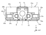
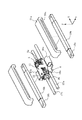
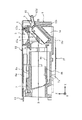
図1〜図5は本発明の第1の実施の形態を示したものであり、図1は外観斜視図、図2は正面図、図3、図4は要部の分解斜視図、そして図5は要部の断面図である。
【0016】
図1〜3において1はキャリッジ、2はキャリッジ1を記録媒体の略半径方向に移動可能に支持する移動手段であり、この移動手段2は後述するトラッキングコイル、貫通孔、軸、内ヨーク、ショートリング、磁石及び外ヨークからなっている。
【0017】
また、図1、図3、図4、図5において3は光ビームを収束させる対物レンズの如き光学素子、4は光学素子3を支持するホルダ(詳細は図5の符号4を参照)、5a、5bはホルダ4の側壁に接着固定され外部の電気基板に接続するフォーカスコイル、6a、6bは板ばね、7はキャリッジ1に接着固定された受け部材であり、ホルダ4は記録媒体の垂直方向(図中Z方向)に移動移動できるように板ばね6a、6bを介して受け部材7に弾性支持されている。
【0018】
図5において8a、8bは受け部材7に設けられ板ばね6a、6bをダンピングするシリコーンゲルを充填する凹部、9はキャリッジ1の傾斜基部1aに接着固定され光ビームの向きを変更される反射ミラー、10a、10bはキャリッジ1の外側面に固定され外部の電気基板と接続するトラッキングコイル(例えば軽量化のために銅クラッドアルミ線にて捲線したもの等)、11は光学素子3を残してキャリッジ1の上面及び両側面を覆うカバー(例えば剛性が高く非磁性のステンレス鋼SUS316Lにて作製したもの)、12はキャリッジ1の底面に配置されるプレート(カバー11と同様の材料にて作製されたもの)であり、トラッキングコイル10a、10b、カバー11、プレート12の何れもがキャリッジ1に接着固定される。
【0019】
また、図1〜図5における13はカバー11に固定され錘の役目を有するたプレート(比重が大きい真鍮C2801等が適用できる)であり、図4における14はトラッキングコイル10a、10bとキャリッジ1との間に配置され該トラッキングコイル10a、10bを固定する接着剤のキャリッジ1内への流入を阻止するプレート、図4、図5の15は反射ミラー9をキャリッジ1の傾斜基部1aに固定保持する押さえ部材である。押さえ部材15は例えば銅のばね材にて作製することができるもので、反射ミラー9の表面の四隅で接触する押圧片15aを有する本体フレーム15bと、その本体フレーム15bの一端に設けられ先端に爪部を有する係止片15cと、係止片15cとは反対側の他端に設けられた折返しの二重重ねになる挟持片15dが備えられており、係止片15cの爪部をキャリッジ1に設けた孔部に差し込んで係止し、その他端の挟持片15dをカバー11とキャリッジ1との間で挟持し係止部位を支点にして反射ミラー9をキャリッジ1の傾斜基部1aに向けて弾性的に押圧して固定保持するようになっている。図6に押圧部材15の外観を斜視図で示す。
【0020】
また、図2〜図4において16a、16bはキャリッジ1に設けられた貫通孔であり、この貫通孔16a、16bにはそれぞれ軸受部が形成され、その軸受部には図1、図3に示すように軸17a、17bが配置されていて、これによってキャリッジ1は軸17a、17bに沿って移動できるようになっている。
【0021】
図1〜3の18a、18bはトラッキングコイル10a、10bの内側に配置された内ヨークであり、その外側には厚さ0.2mm程度の銅のショートリング19a、19bがかしめにより取り付けられていて、内ヨーク18a、18bの上(記録媒体側で図中のZ+方向)には磁石20a、20bが接着固定された外ヨーク21a、21bが配置されている。
【0022】
外ヨーク21a、21bは内ヨーク18a、18bを介して図示していないデッキベースに固定されており、トラッキングコイル10a、10b、貫通孔16a、16b、軸17a、17b、内ヨーク18a、18b、ショートリング19a、19b、磁石20a、20b、外ヨーク21a、21bが組合わさってキャリッジ1を記録媒体の略半径方向に移動可能に支持する移動手段2を構成する。
【0023】
以下、上記の実施の形態につき、その動作について説明する。
【0024】
固定光学系(図示せず)から出射された光ビーム(レーザ光)Bは、図5に示すように、キャリッジ1に設けられた孔部1b及び受け部材7に設けられた孔部7aを通り反射ミラー9でその向きが変更されて光学素子3によって記録媒体(図示せず)上にスポットを形成する。
【0025】
記録媒体から反射された光ビームは再び光学素子3を通って固定光学系に戻り、フォーカスエラー、トラッキングエラー及び記録信号の検出が行われる。
【0026】
フォーカスエラーが検出された場合は、フォーカスコイル5a、5bに電流が流され磁石20a、20bの記録媒体の接線方向(Y方向)端面からの漏れ磁界によってホルダ4が記録媒体の略垂直方向に向けて駆動される。
【0027】
また、トラッキングエラーが検出された場合には、トラッキングコイル10a、10bに電流が流され磁石20a、20bと内ヨーク18a、18bの間の通常の磁気キャップから駆動力を受けてキャリッジ1ごとホルダ4は記録媒体の略半径方向に駆動される。
【0028】
異なるトラックにアクセスする場合もトラッキングコイル10a、10bに電流が流されホルダ4はキャリッジ1ごと記録媒体の略半径方向に駆動される。
【0029】
以上の要領にしたがいホルダ4およびそれに固定保持された光学素子3はフォーカス制御、トラッキング制御、アクセス制御がなされる。
【0030】
本発明の実施の形態では、反射ミラー9を押さえ部材15を使用してキャリッジ1に固定するので、接着剤のみで固定した従来構造のものに比較してキャリッジ1が動作することによる振動やコイルの熱あるいは装置が使われる場所の環境の影響で接着剤にストレスが加わって反射ミラー9の位置がずれたり脱落することはなく、正確な記録再生が実現できることになる。
【0031】
押さえ部材15は、挟持片15dをカバー11とキャリッジ1との間で挟持して固定するようにしたため、挟持片15dをキャリッジ1の孔部に引っ掛けることをせずに、反射ミラー9の上に載せるような形で取り付け作業ができ取り付けの際の作業性も良好である。押さえ部材15の固定にあたってカバー11を利用することにより反射ミラー9が簡単にずれたりキャリッジ1から脱落することはなく、反射ミラー9の設置位置の安定化が図られる。
【0032】
また、押さえ部材15は金属材料からなるものが適用できるが、合成樹脂製のものであってもよく、また、反射ミラー9は接着剤を用いて固定せず押さえ部材15のみで固定することができるものであり、この点については限定されない。
【0033】
図7は押さえ部材15の他の構成例を示したものである。押さえ部材15の係止片15cを単純な鍵型形状とし挟持片15dは折返しのない形状としてもよい。
【0034】
本発明の実施の形態では、図2に示したようにカバー11、トラッキングコイル10a、10b、プレート12等の金属製部材を環状に配置してそれらによる区画領域Mを形成したが、このような区画領域Mを形成してここにキャリッジ1を配置することで該キャリッジ1を軽量化に有利な合成樹脂で作製しても装置全体としての剛性は高められるので制御帯域の広い高性能な光学系駆動装置とすることが可能になる。
【0035】
合成樹脂と金属を接着剤で接着した時の接着力よりも金属同士の接着力のほうが一般に強いが、上記の金属製部材とキャリッジ1とは接着固定する。
【0036】
トラッキングコイル10a、10bはキャリッジ1を駆動するための駆動源であり、電流を流すことにより振動することになるが、該トリッキングコイル10a、10bがキャリッジ1に強く固定されることでトラッキングコイル10a、10bの振動も抑制され、共振が小さいことで結果的に制御帯域が拡大される。
【0037】
図8、図9は本発明の第2の実施の形態を示すものであり、図8は分解状態の外観斜視図であり、図9は要部の断面である。
【0038】
図8、図9に示したものは、キャリッジ1の幅方向(Y方向)に延在させたプレート12に代えてその長手方向(X方向)に延在させたプレート21を配置したもの(他の構成は第1の実施の形態とほぼ同じ)で、このプレート21の一端にはそれと一体になりキャリッジ1の端面に沿って立ち上がりカバー11と接着される起立片21aが設けられており、他端は押さえ部材15の係止片15cに接着されている。
【0039】
プレート21は非磁性のステンレス鋼の板によって作製することができ、これにより、キャリッジ1はその全ての面が金属製部材により取り囲まれることになり、装置の剛性がより一層高められ、制御帯域が広い高性能な光学系駆動装置とすることができる。
【0040】
キャリッジ1の振動に伴って反射ミラー9が振動すると、反射ミラー9を通過する光ビームも振動し信号に振動成分が加わることになり、制御帯域を考慮すると反射ミラー9は他の構成部材よりも振動の影響が大きいといえるが、上記の構成においては、プレート21の他端を押さえ部材15の係止片15cに接着することで押さえ部材15が強固に固定されるとともに金属製部材の環により補強されその部分の剛性が特に改善される結果として反射ミラー9の振動が抑制され、制御帯域を著しく拡大することができることになる。
【0041】
【発明の効果】
本発明によれば、光ビームの向きを変更する反射ミラーの位置ずれや脱落を確実に防止できる。
【0042】
また、本発明によれば、キャリッジを金属製部材の環状配置にて形成した区画領域に配置したので、装置そのものの剛性を高めることが可能となり制御帯域を著しく拡大してその高性能化を図ることができる。
【図面の簡単な説明】
【図1】本発明の第1の実施の形態につき、その外観斜視図である。
【図2】図1の正面を示した図である。
【図3】図1に示した装置の分解状態を示した図である。
【図4】図1に示した装置の要部の分解斜視図である。
【図5】図1に示した装置の要部の断面を示した図である。
【図6】押さえ部材の外観斜視図である。
【図7】押さえ部材の他の構成例を示した外観斜視図である。
【図8】本発明の第2の実施の形態につき、その外観斜視図である。
【図9】図8に示した装置の要部の断面を示した図である。
【符号の説明】
1 キャリッジ
1a 傾斜基部
1b 孔部
2 移動手段
3 光学素子
4 ホルダ
5a フォーカスコイル
5b フォーカスコイル
6a 板ばね
6b 板ばね
7 受け部材
8a 凹部
8b 凹部
9 反射ミラー
10a トラッキングコイル
10b トラッキングコイル
11 カバー
12 プレート
13 プレート
14 プレート
15 押さえ部材
15a 押圧片
15b 本体フレーム
15c 係止片
15d 挟持片
16a 貫通孔
16b 貫通孔
17a 軸
17b 軸
18a 内ヨーク
18b 内ヨーク
19a ショートリング
19b ショートリング
20a 磁石
20b 磁石
21a 外ヨーク
21b 外ヨーク
B 光ビーム
M 区画領域[0001]
TECHNICAL FIELD OF THE INVENTION
The present invention relates to an optical system driving device suitable for supporting and driving an optical system for projecting a light beam on an information recording medium in an optical information recording and / or reproducing apparatus such as an optical disk.
[0002]
[Prior art]
An optical information recording and / or reproducing apparatus needs to drive an optical element such as an objective lens in the vertical direction or the radial direction while following the surface deflection or inclination of the optical disk. The optical element and holder are resiliently supported to allow the recording medium to move in a substantially vertical direction, while the optical element and the holder are incorporated in a carriage that can move along the recording medium in a substantially radial direction. Has become.
[0003]
Such a carriage is usually formed of a synthetic resin, and in addition to the optical element and the holder, an actuator for moving the optical element together with the holder in the vertical direction of the recording medium and a light beam incident on the carriage are provided. A reflection mirror or the like for changing the direction of the carriage is disposed, and a metal cover for increasing the rigidity of the carriage is mounted around the reflection mirror (see, for example, Patent Document 1).
[0004]
[Patent Document 1]
JP-A-9-54960.
[0005]
By the way, the above-mentioned driving device has the following problems.
[0006]
Of the members arranged in the carriage, the reflection mirror is fixed to the base using an adhesive, but the carriage itself moves in substantially the radial direction of the recording medium, so that it is inevitable that vibration is applied, In addition, it is not unusual for the temperature of the driving device to exceed 50 ° C. during the operation of the driving device due to the influence of a coil, an electric circuit, and the like installed along with the carriage, and further, an optical system driving device incorporating the carriage is provided. Since the equipment is used in various environments such as high temperature, low temperature, and high humidity depending on the application, there is a disadvantage that the adhesive strength of the adhesive for fixing the reflection mirror is reduced and the position of the reflection mirror is shifted or dropped. was there.
[0007]
The reflection mirror is an optical component, and unlike other components, precise position accuracy of 0.1 degrees is required when angled to achieve accurate recording and reproduction. Therefore, there is a concern that the displacement or dropout of the reflection mirror becomes more remarkable because the bonding area becomes smaller accordingly.
[0008]
In addition, the carriage is often made of synthetic resin in order to reduce the size, weight, and cost, but since the rigidity of the carriage is inevitably reduced compared to the case where the carriage is manufactured by aluminum die casting, the carriage and the holder are driven. In the case of controlling, a sufficient control band cannot be obtained, and there is a limit in improving the performance of such a device.
[0009]
In this regard, in
[0010]
[Problems to be solved by the invention]
An object of the present invention has been made in view of the above circumstances, and an object of the present invention is to propose a compact and high-performance optical system driving device.
[0011]
[Means for Solving the Problems]
The present invention provides a holder including an optical element for converging a light beam, a carriage for supporting the holder so as to be movable in a substantially vertical direction and / or a substantially radial direction of a recording medium, and a method for moving the carriage in a substantially radial direction of the recording medium. An optical system driving device having at least a moving means for movably supporting, a reflecting mirror installed on a carriage to change the direction of a light beam, and a cover that locally or entirely surrounds the carriage.
The carriage has a holding member that locks one end to the carriage, clamps the other end between the cover and the carriage, and elastically presses the reflection mirror toward the carriage with the locking portion as a fulcrum to fix and hold the reflection mirror. An optical system driving device characterized in that:
[0012]
Preferably, the cover is made of a metal material, and the cover and at least one metal member in contact with the cover are annularly arranged to form a partitioned area, and the carriage is arranged in the partitioned area.
[0013]
The holding member is made of a metal material, and a part of the holding member constitutes a metal member.
[0014]
BEST MODE FOR CARRYING OUT THE INVENTION
Hereinafter, the present invention will be described more specifically with reference to the drawings.
[0015]
1 to 5 show a first embodiment of the present invention. FIG. 1 is an external perspective view, FIG. 2 is a front view, FIGS. 3 and 4 are exploded perspective views of main parts, and FIG. 5 is a cross-sectional view of a main part.
[0016]
1 to 3,
[0017]
1, 3, 4, and 5,
[0018]
In FIG. 5, 8a and 8b are concave portions provided on the receiving
[0019]
[0020]
2 to 4,
[0021]
[0022]
The
[0023]
Hereinafter, the operation of the above embodiment will be described.
[0024]
A light beam (laser light) B emitted from a fixed optical system (not shown) passes through a hole 1b provided in the
[0025]
The light beam reflected from the recording medium passes through the
[0026]
When a focus error is detected, current flows through the focus coils 5a and 5b, and the
[0027]
When a tracking error is detected, an electric current is applied to the tracking coils 10a and 10b to receive a driving force from a normal magnetic cap between the
[0028]
Also when accessing different tracks, a current flows through the tracking coils 10a and 10b, and the
[0029]
According to the above procedure, the focus control, the tracking control, and the access control are performed on the
[0030]
In the embodiment of the present invention, the
[0031]
The holding
[0032]
The holding
[0033]
FIG. 7 shows another configuration example of the holding
[0034]
In the embodiment of the present invention, as shown in FIG. 2, metal members such as the
[0035]
Generally, the metal-to-metal bonding force is stronger than the bonding force when the synthetic resin and the metal are bonded with an adhesive, but the metal member and the
[0036]
The tracking coils 10a and 10b are driving sources for driving the
[0037]
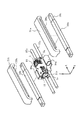
8 and 9 show a second embodiment of the present invention. FIG. 8 is an external perspective view of an exploded state, and FIG. 9 is a cross section of a main part.
[0038]
8 and 9 show the arrangement in which the
[0039]
The
[0040]
When the
[0041]
【The invention's effect】
ADVANTAGE OF THE INVENTION According to this invention, the position shift of a reflection mirror which changes the direction of a light beam, or falling off can be prevented reliably.
[0042]
Further, according to the present invention, since the carriage is disposed in the partitioned area formed by the annular arrangement of the metal members, the rigidity of the apparatus itself can be increased, and the control band is significantly expanded to improve the performance. be able to.
[Brief description of the drawings]
FIG. 1 is an external perspective view of a first embodiment of the present invention.
FIG. 2 is a front view of FIG.
FIG. 3 is a view showing a disassembled state of the device shown in FIG. 1;
4 is an exploded perspective view of a main part of the device shown in FIG.
5 is a diagram showing a cross section of a main part of the device shown in FIG. 1;
FIG. 6 is an external perspective view of a holding member.
FIG. 7 is an external perspective view showing another configuration example of the pressing member.
FIG. 8 is an external perspective view of a second embodiment of the present invention.
9 is a diagram showing a cross section of a main part of the device shown in FIG. 8;
[Explanation of symbols]
REFERENCE SIGNS
Claims (3)
前記キャリッジに、一端をキャリッジに係止し他端をカバーとキャリッジとの間で挟持し該係止部位を支点に反射ミラーをキャリッジに向け弾性的に押圧して固定保持する押さえ部材を配置したことを特徴とする光学系駆動装置。A holder including an optical element for converging a light beam, a carriage supporting the holder so as to be movable in a substantially vertical direction and / or a substantially radial direction of the recording medium, and supporting the carriage so as to be movable in a substantially radial direction of the recording medium. An optical system driving device having at least a moving means, a reflecting mirror installed on the carriage to change the direction of the light beam, and a cover that locally or entirely surrounds the carriage.
On the carriage, a pressing member is disposed which locks one end to the carriage, clamps the other end between the cover and the carriage, and elastically presses the reflecting mirror toward the carriage with the locking portion as a fulcrum to fix and hold the reflecting mirror. An optical system driving device characterized by the above-mentioned.
Priority Applications (1)
| Application Number | Priority Date | Filing Date | Title |
|---|---|---|---|
| JP2002316252A JP3984148B2 (en) | 2002-10-30 | 2002-10-30 | Optical system drive |
Applications Claiming Priority (1)
| Application Number | Priority Date | Filing Date | Title |
|---|---|---|---|
| JP2002316252A JP3984148B2 (en) | 2002-10-30 | 2002-10-30 | Optical system drive |
Publications (2)
| Publication Number | Publication Date |
|---|---|
| JP2004152402A true JP2004152402A (en) | 2004-05-27 |
| JP3984148B2 JP3984148B2 (en) | 2007-10-03 |
Family
ID=32460009
Family Applications (1)
| Application Number | Title | Priority Date | Filing Date |
|---|---|---|---|
| JP2002316252A Expired - Fee Related JP3984148B2 (en) | 2002-10-30 | 2002-10-30 | Optical system drive |
Country Status (1)
| Country | Link |
|---|---|
| JP (1) | JP3984148B2 (en) |
Cited By (1)
| Publication number | Priority date | Publication date | Assignee | Title |
|---|---|---|---|---|
| JP4870237B1 (en) * | 2011-06-27 | 2012-02-08 | パナソニック株式会社 | Laser light source device |
-
2002
- 2002-10-30 JP JP2002316252A patent/JP3984148B2/en not_active Expired - Fee Related
Cited By (1)
| Publication number | Priority date | Publication date | Assignee | Title |
|---|---|---|---|---|
| JP4870237B1 (en) * | 2011-06-27 | 2012-02-08 | パナソニック株式会社 | Laser light source device |
Also Published As
| Publication number | Publication date |
|---|---|
| JP3984148B2 (en) | 2007-10-03 |
Similar Documents
| Publication | Publication Date | Title |
|---|---|---|
| JP4868662B2 (en) | Optical element actuator | |
| US7016125B2 (en) | Objective lens-driving apparatus | |
| JP5108927B2 (en) | Optical element actuator | |
| JP3984148B2 (en) | Optical system drive | |
| KR100569915B1 (en) | Apparatus of optical disk drive | |
| JP2011123990A (en) | Actuator for optical element | |
| US6996039B2 (en) | Optical pick-up actuator | |
| KR100361498B1 (en) | Supporting structure of actuator for tilting drive | |
| JPH0268730A (en) | head transfer device | |
| JP4011760B2 (en) | Objective lens driving device and optical disk device including the same | |
| JPH09306003A (en) | Object lens actuator | |
| US7529047B2 (en) | Actuator for an optical scanning device | |
| JP2005149569A (en) | Optical head device | |
| KR100548246B1 (en) | Lens overhang actuator on optical disc drive | |
| JPH08263848A (en) | Objective lens inclination adjusting mechanism | |
| KR100569922B1 (en) | Optical disk drive unit | |
| US20080159090A1 (en) | Optical pickup and disk drive device | |
| KR100569919B1 (en) | Optical disk drive unit | |
| JP4414590B2 (en) | Optical system drive | |
| KR100569921B1 (en) | Optical disk drive unit | |
| JP2003222780A (en) | Actuator of optical element | |
| WO2004038709A1 (en) | Objective lens driving device | |
| KR20010109532A (en) | Actuator for optical pickup | |
| JPH0973642A (en) | Optical pickup device | |
| KR20050074786A (en) | Apparatus of actuator and optical drive |
Legal Events
| Date | Code | Title | Description |
|---|---|---|---|
| A621 | Written request for application examination |
Free format text: JAPANESE INTERMEDIATE CODE: A621 Effective date: 20050808 |
|
| A977 | Report on retrieval |
Free format text: JAPANESE INTERMEDIATE CODE: A971007 Effective date: 20070402 |
|
| A131 | Notification of reasons for refusal |
Free format text: JAPANESE INTERMEDIATE CODE: A131 Effective date: 20070417 |
|
| A521 | Written amendment |
Free format text: JAPANESE INTERMEDIATE CODE: A523 Effective date: 20070604 |
|
| RD03 | Notification of appointment of power of attorney |
Free format text: JAPANESE INTERMEDIATE CODE: A7423 Effective date: 20070604 |
|
| TRDD | Decision of grant or rejection written | ||
| A01 | Written decision to grant a patent or to grant a registration (utility model) |
Free format text: JAPANESE INTERMEDIATE CODE: A01 Effective date: 20070626 |
|
| A61 | First payment of annual fees (during grant procedure) |
Free format text: JAPANESE INTERMEDIATE CODE: A61 Effective date: 20070705 |
|
| FPAY | Renewal fee payment (event date is renewal date of database) |
Free format text: PAYMENT UNTIL: 20100713 Year of fee payment: 3 |
|
| FPAY | Renewal fee payment (event date is renewal date of database) |
Free format text: PAYMENT UNTIL: 20100713 Year of fee payment: 3 |
|
| FPAY | Renewal fee payment (event date is renewal date of database) |
Free format text: PAYMENT UNTIL: 20100713 Year of fee payment: 3 |
|
| FPAY | Renewal fee payment (event date is renewal date of database) |
Free format text: PAYMENT UNTIL: 20110713 Year of fee payment: 4 |
|
| FPAY | Renewal fee payment (event date is renewal date of database) |
Free format text: PAYMENT UNTIL: 20120713 Year of fee payment: 5 |
|
| FPAY | Renewal fee payment (event date is renewal date of database) |
Free format text: PAYMENT UNTIL: 20130713 Year of fee payment: 6 |
|
| LAPS | Cancellation because of no payment of annual fees |