JP2004152902A - Positioning device - Google Patents
Positioning device Download PDFInfo
- Publication number
- JP2004152902A JP2004152902A JP2002314926A JP2002314926A JP2004152902A JP 2004152902 A JP2004152902 A JP 2004152902A JP 2002314926 A JP2002314926 A JP 2002314926A JP 2002314926 A JP2002314926 A JP 2002314926A JP 2004152902 A JP2004152902 A JP 2004152902A
- Authority
- JP
- Japan
- Prior art keywords
- linear motor
- gravity
- reaction force
- center
- moving table
- Prior art date
- Legal status (The legal status is an assumption and is not a legal conclusion. Google has not performed a legal analysis and makes no representation as to the accuracy of the status listed.)
- Pending
Links
Images

Classifications
-
- G—PHYSICS
- G03—PHOTOGRAPHY; CINEMATOGRAPHY; ANALOGOUS TECHNIQUES USING WAVES OTHER THAN OPTICAL WAVES; ELECTROGRAPHY; HOLOGRAPHY
- G03B—APPARATUS OR ARRANGEMENTS FOR TAKING PHOTOGRAPHS OR FOR PROJECTING OR VIEWING THEM; APPARATUS OR ARRANGEMENTS EMPLOYING ANALOGOUS TECHNIQUES USING WAVES OTHER THAN OPTICAL WAVES; ACCESSORIES THEREFOR
- G03B27/00—Photographic printing apparatus
- G03B27/32—Projection printing apparatus, e.g. enlarger, copying camera
- G03B27/52—Details
- G03B27/58—Baseboards, masking frames, or other holders for the sensitive material
-
- G—PHYSICS
- G03—PHOTOGRAPHY; CINEMATOGRAPHY; ANALOGOUS TECHNIQUES USING WAVES OTHER THAN OPTICAL WAVES; ELECTROGRAPHY; HOLOGRAPHY
- G03F—PHOTOMECHANICAL PRODUCTION OF TEXTURED OR PATTERNED SURFACES, e.g. FOR PRINTING, FOR PROCESSING OF SEMICONDUCTOR DEVICES; MATERIALS THEREFOR; ORIGINALS THEREFOR; APPARATUS SPECIALLY ADAPTED THEREFOR
- G03F7/00—Photomechanical, e.g. photolithographic, production of textured or patterned surfaces, e.g. printing surfaces; Materials therefor, e.g. comprising photoresists; Apparatus specially adapted therefor
- G03F7/70—Microphotolithographic exposure; Apparatus therefor
- G03F7/70691—Handling of masks or workpieces
- G03F7/70758—Drive means, e.g. actuators, motors for long- or short-stroke modules or fine or coarse driving
-
- G—PHYSICS
- G03—PHOTOGRAPHY; CINEMATOGRAPHY; ANALOGOUS TECHNIQUES USING WAVES OTHER THAN OPTICAL WAVES; ELECTROGRAPHY; HOLOGRAPHY
- G03F—PHOTOMECHANICAL PRODUCTION OF TEXTURED OR PATTERNED SURFACES, e.g. FOR PRINTING, FOR PROCESSING OF SEMICONDUCTOR DEVICES; MATERIALS THEREFOR; ORIGINALS THEREFOR; APPARATUS SPECIALLY ADAPTED THEREFOR
- G03F7/00—Photomechanical, e.g. photolithographic, production of textured or patterned surfaces, e.g. printing surfaces; Materials therefor, e.g. comprising photoresists; Apparatus specially adapted therefor
- G03F7/70—Microphotolithographic exposure; Apparatus therefor
- G03F7/70691—Handling of masks or workpieces
- G03F7/70766—Reaction force control means, e.g. countermass
Landscapes
- Physics & Mathematics (AREA)
- General Physics & Mathematics (AREA)
- Chemical & Material Sciences (AREA)
- Chemical Kinetics & Catalysis (AREA)
- Exposure And Positioning Against Photoresist Photosensitive Materials (AREA)
- Container, Conveyance, Adherence, Positioning, Of Wafer (AREA)
- Exposure Of Semiconductors, Excluding Electron Or Ion Beam Exposure (AREA)
Abstract
Description
【0001】
【発明の属する技術分野】
本発明は、半導体リソグラフィ工程等の高精度の加工に好適に用いられる位置決め装置に関するものである。
【0002】
【従来の技術】
従来、半導体デバイス等の製造に用いられる露光装置としては、基板(ウエハやガラス基板)をステップ移動させながら基板上の複数の露光領域に原版(レチクルやマスク)のパターンを投影光学系を介して順次露光するステップ・アンド・リピート型の露光装置(「ステッパ」と称することもある)や、ステップ移動と走査露光とを繰り返すことにより、基板上の複数の領域に露光転写を繰り返すステップ・アンド・スキャン型の露光装置(「スキャナ」と称することもある)が代表的である。
【0003】
特に、ステップ・アンド・スキャン型は、スリットにより制限して投影光学系の比較的光軸に近い部分のみを使用しているため、より高精度、かつ、広画角な微細パターンの露光が可能となっている。
【0004】
これら露光装置はウエハやレチクルを高速で移動させて位置決めするステージ装置(ウエハステージ、レチクルステージ)を有している(例えば、特許文献1を参照)。
【0005】
【特許文献1】
特開昭62−88526号公報
【0006】
【発明が解決しようとする課題】
上記特許文献1は、XY可動ガイドの駆動位置高さおよびこの駆動位置高さとステージの重心位置高さを同一高さに設定し、ステージのヨーイング,ピッチング等を防止する技術について開示している。しかしながら、このようなステージ装置においては、可動部の移動により生じる推進反力を吸収する反力吸収機構が構成されていないため、ステージを駆動すると加減速に伴う慣性力の反力が生じ、これが定盤に伝わると定盤の揺れや振動を引き起こす原因となり、露光装置の機構系の固有振動が、その定盤の揺れや振動により励起され、高周波振動となって高速な駆動、高精度な位置決めを妨げる要因となるという課題があった。
【0007】
そこで、本発明は、ステージの移動に伴う振動や揺れを軽減し、高速、かつ、高精度な位置決めが可能な位置決め装置、およびその位置決め装置を適用した露光装置等を提供することを目的とする。特に、ステージの移動により発生するモーメント反力に伴う定盤の振動や揺れを軽減することを、目的とする。
【0008】
【課題を解決するための手段】
上記課題を解決し、目的を達成するべく、本発明にかかる位置決め装置及び、露光装置等は、主として以下の構成よりなることを特徴とする。
【0009】
すなわち、可動部と、該可動部の移動により生じる推進反力を吸収する反力吸収機構を有する位置決め装置は、
基準面と該基準面上を移動可能に支持されている可動部の重心位置の間の第1距離と前記基準面と前記反力吸収機構の重心位置の間の第2距離を略同一、および/または、前記第2距離と前記基準面と前記可動部を該基準面内に推進させるためのモーター可動子の間の第3距離を略同一にすることを特徴とする。
【0010】
好ましくは、上記の位置決め装置において、前基反力吸収機構は、前記基準面上を移動可能に構成されている、前記可動部を駆動するモーターの固定子である。
【0011】
また、平面内の略直交する2軸方向に移動可能な可動部と、該可動部の各軸方の移動により生じる推進反力を吸収する第1及び第2反力吸収機構を有する位置決め装置は、
基準平面と、該基準平面上を移動可能に支持されている前記可動部を含むX移動体の重心位置と、の間の第4距離と、
前記基準平面と、前記X移動体の第1移動方向に対応する第1反力吸収機構の重心位置と、の間の第5距離と、を略同一距離に構成し、
前記基準平面と、該基準平面を移動可能に支持されている前記可動部を含むY移動体の重心位置と、の間の第6距離と、
前記基準平面と、前記Y移動体の第2移動方向に対応する第2反力吸収機構の重心位置と、の間の第7距離と、を略同一距離に構成していることを特徴とする。
【0012】
好ましくは、上記の位置決め装置において、前記X移動体には、前記可動部と、該可動部上に構成される第2可動部と、該可動体を第1方向に推進させる推進力を該可動体に伝達する第1ビーム材と、該可動部の移動を第1方向にガイドするための第1ガイド部材と、該可動部を第1方向に推進するための第1モーター可動子と、を含む。
【0013】
好ましくは、上記の位置決め装置において、前記Y移動体には、前記可動部と、該可動部上に構成される第2可動部と、該可動体を第2方向に推進させる推進力を該可動体に伝達する第2ビーム材と、該可動部の移動を第2方向にガイドするための第2ガイド部材と、該可動部を第2方向に推進するための第2モーター可動子と、を含む。
【0014】
好ましくは、上記の位置決め装置において、前記第2可動部は、前記可動部の位置及び姿勢を調整するための微動ステージである。
【0015】
好ましくは、上記の位置決め装置において、前記X移動体には、前記可動体を第1方向に推進させる推進力を該可動体に伝達する第1ビーム材と、該第1方向の移動をガイドするための第1ガイド部材と、該可動部を第1方向に推進するための第1モーター可動子と、を含む。
【0016】
好ましくは、上記の位置決め装置において、前記Y移動体には、前記可動体を第2方向に推進させる推進力を該可動体に伝達する第2ビーム材と、該第2方向の移動をガイドするための第2ガイド部材と、該可動部を第2方向に推進するための第2モーター可動子と、を含む。
【0017】
また、平面内の略直交する2軸方向に移動可能な可動部と、該可動部の各軸方の移動により生じる推進反力を吸収する第1及び第2反力吸収機構を有する位置決め装置は、
基準平面と、該基準平面上を移動可能に支持されている前記可動部を第1方向にガイドする第1ガイド部材の重心位置と、の間の第8距離と、
前記基準平面と、前記可動部の第1移動方向に対応する第1反力吸収機構の重心位置と、の間の第9距離と、を略同一距離に構成し、
前記基準平面と、該基準平面上を移動可能に支持されている前記可動部を第2方向にガイドする第2ガイド部材の重心位置と、の間の第10距離と、
前記基準平面と、前記可動部の第2移動方向に対応する第2反力吸収機構の重心位置と、の間の第11距離と、を略同一距離に構成していることを特徴とする。
【0018】
また、平面内の略直交する2軸方向に移動可能な可動部と、該可動部の各軸方の移動により生じる推進反力を吸収する第1及び第2反力吸収機構を有する位置決め装置は、
基準平面と、前記可動部を該基準平面内の第1方向に推進させるための第1モーター可動子と、の間の第12距離と、
前記基準平面と、前記可動部の第1移動方向に対応する第1反力吸収機構の重心位置と、の間の第13距離と、を略同一距離に構成し、
前記基準平面と、前記可動部を該基準平面内の第2方向に推進させるための第2モーター可動子と、の間の第14距離と、
前記基準平面と、前記可動部の第2移動方向に対応する第2反力吸収機構の重心位置と、の間の第15距離と、を略同一距離に構成していることを特徴とする。
【0019】
好ましくは、上記の位置決め装置において、前記第8距離と、前記第12距離と、は略同一距離に構成されている。
【0020】
好ましくは、上記の位置決め装置において、前記第10距離と、前記第14距離と、は略同一距離に構成されている。
【0021】
好ましくは、上記の位置決め装置において、前記可動部の移動を各移動方向に案内する前記第1ガイド部材および/または前記第2ガイド部材は、前記基準平面の方向に離間して構成される複数個のガイド部材により構成される。
【0022】
好ましくは、上記の位置決め装置において、前基第1及び第2反力吸収機構は、前記基準平面上を移動可能に構成されている、前記可動部を駆動するモーターの固定子である。
【0023】
また、露光装置は、
原版を保持し、所定の位置に駆動して、所定の位置に位置決めする原版位置決め装置と、
基板を保持し、所定の位置に駆動して、所定の位置に位置決めする基板位置決め装置と、
前記基板に原版のパターンを投影する投影光学系と、
を含み、
前記原版位置決め装置及び/または前記基板位置決め装置は、上記の位置決め装置の構成を有することを特徴とする。
【0024】
また、デバイス製造方法は、
基板に感光剤を塗布する工程と、
前記基板を上記の露光装置によって露光する工程と、
前記基板を現像する工程と、
を含むことを特徴とする。
【0025】
【発明の実施の形態】
以下、本発明にかかる実施形態を図面を参照して説明する。
【0026】
<第1実施形態>
<位置決め装置の構成>
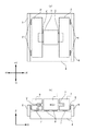
図1は本発明にかかる第1実施形態の位置決め装置の構成を説明する図であり、(a)はその位置決め装置の平面図、(b)はその正面図である。図中において、参照番号1は移動テーブルであり、2及び2’は移動テーブル1をY軸方向に駆動するためのYリニアモーター可動子、3及び3’は同じくYリニアモーター固定子である。4はステージ定盤であり、ガイド面としてその上面には移動テーブル1、Yリニアモータ固定子3、3’等が搭載される。5及び5’はYリニアモーター固定子のヨーイング(XY平面内におけるYリニアモータ固定子3及び3’の偏揺れ,偏走)を規制するYヨーイングガイドである。
【0027】
また、6、6’及び7、7’及び8は静圧軸受であり、それぞれYリニアモーター固定子3,3’の側面部、底面部及び移動テーブル1の底面をそれぞれ静圧空気で浮上させている。
【0028】
移動テーブル1は、ステージ定盤4に対して静圧軸受8により非接触に支持されており(図1(b))、Y方向に移動可能である。移動テーブル1の両側には、移動テーブル1をY方向に沿って駆動させるためのYリニアモーター可動子2,2’が固定されており、Yリニアモータ可動子2、2’は、図1(b)に示されるように、Yリニアモーター固定子3,3’の凹部内に一定の間隙を有した状態で移動可能に構成されている。
【0029】
ここで、Yリニアモーター固定子3,3’は、ステージ定盤4に対して静圧軸受7,7’によって非接触に支持され、同時にYヨーイングガイド5,5’に対しても静圧軸受6,6’によって非接触に支持されており、Y方向に沿って移動可能である。また、このYリニアモーター固定子3,3’は、所定の質量を有しており、後述する反力カウンターとして機能することも可能である。
【0030】
Yリニアモーター可動子2,2’は移動テーブル1に結合されており、可動子の駆動により移動テーブル1はY方向に移動する。このとき、Yリニアモーター固定子3、3’は、移動テーブル1の移動において発生する駆動力の反力(駆動反力)を受けることになる。Yリニアモーター固定子はステージ定盤4上を移動可能に支持されており、この駆動反力によりYリニアモーター固定子3,3’はステージ定盤4上を移動テーブル1の移動方向とは逆向きに移動する。
【0031】
すなわち、Yリニアモーター固定子3,3’がステージ定盤4上を移動することにより、駆動反力がステージ定盤4に伝達されるのを防止することができ、Yリニアモーター固定子3、3’が反力カウンターの役割を果たすことになる。
【0032】
本実施形態では、例えば、移動テーブル1を+Y方向に駆動すると、Yリニアモーター固定子3、3’は−Y方向に駆動反力を受けて、このマイナス方向の力を駆動力として、固定子3、3’は−Y方向に移動する。
【0033】
位置決め装置において、移動テーブルを所定の位置に位置決めするためには、不図示のレーザー干渉計を1個または複数個設け、レーザー干渉計により検出された位置情報に基づいて位置制御をして移動テーブル1の位置決めを行い、同様に、平面内を移動する反力カウンターであるYリニアモーター固定子3,3’を位置決めするために、不図示の干渉計により固定子の位置を計測することも可能である。
【0034】
図1(a),(b)に示した構成によれば、移動テーブル1が移動する際の加減速時の反力をYリニアモーター固定子3,3’が反力カウンターとなって受け、Yリニアモーター固定子3,3’が移動することにより、駆動反力が固定子3、3’の運動エネルギーに変換されることになる。このことにより、移動テーブル1の移動により発生する駆動反力がステージ定盤4を加振することを防止するとともに、位置決め装置を組込んだ装置が設置されている床面に振動が伝達するのを防止することができるので、自機ばかりではなく、他の装置に対する外乱(加振源)となる原因を排除することが可能になる。
【0035】
更に、Yリニアモーター固定子3,3’が移動テーブル1の加速度に応じてステージ定盤4上を移動するので、移動テーブル1が移動する時の偏荷重を小さくすることができるので、例えば、ウエハを保持して位置決めする場合では、移動テーブルの移動範囲全域において、均一な位置、姿勢を決めることが可能になり、ウエハを露光する場合には、オーバーレイ精度の向上を図ることができる。
本実施形態によれば、移動テーブル1が移動する方向と反対の方向にYリニアモーター固定子3、3’が移動するため、移動テーブル1とYリニアモーター固定子3,3’とを含めた全体の構成の重心位置の変動を抑えることができるので、移動テーブル1が移動した場合でも、ステージ定盤4上の荷重バランスが大きく変化することはなく、結果として移動テーブル1の移動による偏荷重を小さくすることができる。
【0036】
さらに、本実施形態によれば、Yリニアモーター固定子3、3’を独立に設けている。そのため、Yリニアモーター可動子2,2’に働く力が異なっていても、それぞれのYリニアモーター固定子3,3’が別個に移動することにより、反力を打ち消すことができる。例えば、移動テーブル1をθ方向に回転移動させる場合や、移動テーブル1に載置された物体がX方向に偏荷重を持っている場合などは、Yリニアモーター可動子2,2’の出力が異なることが想定されるが、このような場合においても、Yリニアモーター固定子3、3’を別個に移動可能な構成にすることで、効果的な駆動反力の相殺が可能になる。
【0037】
図1(a),(b)のように構成することで、移動テーブル1の加減速の際に発生する駆動反力は、Yリニアモーター固定子3,3’が逆方向に移動することによって運動エネルギーに変換され、吸収される。これにより、駆動反力による定盤の揺れや振動が抑制できる。
【0038】
<重心まわりのモーメントの吸収>
しかし、移動テーブル1の重心高さと固定子Yリニアモーター重心高さとが不一致の場合には、ステージ定盤を含めた構造体の重心周りのモーメントを考慮する必要が生じる。すなわち、移動テーブル1の移動により装置全体に加わるx軸回りのモーメントと、Yリニアモーター固定子2,2’の移動により装置全体に加わるx軸回りのモーメントが釣り合わず、ステージ定盤4にはその差分のモーメントが加わることになる。
【0039】
例えば、図4に示すように、移動テーブル1の重心位置G1(ステージ定盤4の上面を基準としたZ方向の高さ)がYリニアモーター固定子3,3’の重心位置G2よりも高かった場合を想定して、移動テーブル1を+Y方向(図2Aの左方向)に駆動すると、これによりステージ定盤4には時計回りの−ωX方向のモーメント(モーメント反力)が加わる。
【0040】
一方、Yリニアモーター固定子3、3’は−Y方向に駆動反力を受けて−Y方向に移動するので、これによりステージ定盤4には反時計回りの+ωX方向のモーメント(モーメント反力)が加わる。
【0041】
作用する力が等しければ重心の高い前者のモーメントの方が大きくなるのは自明であるので、結局ステージ定盤4に対しては−ωX方向のモーメントが支配的に加わることになる。このように重心位置が異なる場合、Yリニアモーター固定子3,3’の構成ではモーメント反力をキャンセルすることができず、モーメント反力によりステージ定盤4が加振され、装置を設置する床の振動も励起し、自他の装置に振動を励起してしまうことになる。
【0042】
本実施形態にかかる位置決め装置の構成(図1(a),(b))は、上記の図2Aに示すような、モーメント反力の影響を解消するために、Yリニアモーター固定子3,3’の重心高さ(G2)と、移動テーブル1の重心高さ(G1)を等しく構成している。より厳密には、Yリニアモーター固定子3,3’の重心高さ(G2)と、移動テーブル1とYリニアモーター可動子2,2’とを含む移動体全体の重心高さ(G1)とを等しくなる様に構成したものである。この構成により、移動テーブル1の移動によって生じる駆動反力を、ステージ定盤4に加わるモーメント反力も含めて完全にキャンセルすることが可能になる。
【0043】
<リニアモーターの作用線>
また、本実施形態では、さらに図1(b)に示す通り、Yリニアモーター可動子に加わる力の作用線の高さ(G3)も、Yリニアモーター固定子3,3’の重心高さ(G2)と一致させることが望ましい。これにより、Yリニアモーター固定子3,3’の重心高さにYリニアモーター推力が作用することになるので、Yリニアモーター固定子3,3’単体の動作としても、その重心回りのモーメントを発生させないので、ステージ定盤1に対する振動を励起することが避けられるという効果が得られる。同時に移動テーブル1の重心高さ(G1)、又は移動テーブル1とYリニアモーター可動子2,2’とを含む移動体全体の重心高さをYリニアモーター推力が作用することになるので、移動テーブル1、又は移動テーブル1とYリニアモーター可動子2,2’とを含む移動体全体のみの動作としても、その重心回りのモーメントを発生させないのでステージ定盤1に対する振動を励起することが避けられる。
【0044】
以上の構成により、移動テーブル1の移動方向であるY軸方向の駆動反力を、固定子の移動により吸収し、さらに、移動テーブル1の重心高さ(G1)と、リニアモータ固定子3、3’の重心高さ(G2)、リニアモータ作用線の高さ(G3)を一致させることにより、x軸回りのモーメント、z軸回りのモーメント反力の発生を防ぐことが可能になり、ステージ定盤4の揺れや振動を励起することがない、高速かつ高精度な位置決め装置の実現が可能になる。
【0045】
また、本実施形態では、移動テーブル1のガイド面とYリニアモーター固定子3,3’のガイド面を同一の面(ステージ定盤4)として説明してきたが、これを平行な相異なる面上に構成した場合であっても、同様の効果が得られる。
【0046】
<第2実施形態>
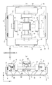
図2は本発明にかかる第2実施形態の位置決め装置の構成を説明する図であり、(a)はその位置決め装置の平面図、(b)はその正面図である。図中、図1と同じ構成要素は同一の参照番号を付している。9は移動テーブル1上に配置され、上下動およびチルト動作をすることが可能な微動テーブルであり、10は微動テーブル9上に配置された反射ミラーであり、11は移動テーブル1上に構成され微動テーブルの上下動およびチルト動作を行う複数の微動アクチュエーターである。
【0047】
12は移動テーブル1をx軸方向に移動させるXビーム(「梁」以下、同じ。)、13は同じく移動テーブル1をY方向に移動させるYビームである。Xビーム12の両側面(12a,12b)には、移動テーブル1のY方向の移動をガイドするYガイド面が構成されており、Yビーム13の両側面(13a,13b)には移動テーブル1のX方向の移動をガイドするXガイド面が構成されている。Xビーム12に構成されるYガイド面及びYビームに構成されるXガイド面と、移動テーブル1との間には、図示しない静圧軸受が配置され、非接触で力の伝達と直動ガイド動作を行っている。
【0048】
14,14’はYビーム13の両端に配置されたYスライダーであり、15,15’はそのYスライダー下面に配置された静圧軸受である。同じく16,16’はXビーム12の両端に配置されたXスライダーであり、その下面には図示しない静圧パッドが同様に配置されている。
【0049】
17,17’はXビーム12をX方向に駆動するためのXリニアモーター可動子であり、18,18’は同じくXリニアモーター固定子である。20,20’はXリニアモーター固定子18,18’のヨーイングを規制するXヨーガイドである。また19,19’はXリニアモーター固定子18,18’の側面を静圧空気で浮上させる静圧軸受であり、同様の静圧軸受が図示しない底面にも配置されている。
【0050】
移動テーブル1は、ステージ定盤4に対して静圧軸受8により非接触に支持されており(図2(b)を参照)、XY方向に移動可能である。移動テーブル1にはXビーム12及びYビーム13が略直交して貫かれており、移動テーブル1のXビーム12のYガイド面及びYビーム13のXガイド面との対向面には力の伝達と緒駆動ガイドを行う図示しない静圧軸受が配置されているので、常に両ビームの交点の位置に移動テーブル1が位置する。
【0051】
Xビーム12及びYビーム13の両端にはそれぞれXスライダー16,16’とYスライダー14,14’が締結されており、各スライダーの下面にはそれぞれ静圧軸受が配置されているので、Xビーム12とXスライダー16,16’の結合体はX方向に移動可能であり、Yビーム13とYスライダー14,14’の結合体はY方向に移動可能である(図2(b)を参照)。
【0052】
Xスライダー16,16’及びYスライダー14,14’には、それぞれXリニアモーター可動子17,17’及びYリニアモーター可動子2,2’が締結されており、各リニアモーターで発生した推力によって各スライダーが駆動される。Xリニアモーター可動子17,17’とYリニアモーター可動子には対向してXリニアモーター固定子18,18’及びYリニアモーター固定子3,3’が配置されており、これらで各移動方向のリニアモーターが構成されている。
【0053】
ここで、Xリニアモーター固定子18,18’とYリニアモーター固定子3,3’は、ステージ定盤4に対して静圧軸受7,7’(Xリニアモーター側は図示せず)によって非接触に支持され、同時にXヨーイングガイド20,20’とYヨーイングガイド5,5’に対しても静圧軸受19,19’、6,6’によって非接触に支持されており、それぞれX方向及びY方向に沿って移動可能である。
【0054】
<駆動反力の吸収>
また、このXリニアモーター固定子18,18’とYリニアモーター固定子3,3’は、それぞれ所定の質量を持ち、第1実施形態と同様に反力カウンターの機能を備えている。Xリニアモーター可動子17,17’及びYリニアモーター可動子2,2’はそれぞれXスライダー16,16’及びYスライダー14,14’に締結されており、それぞれX方向及びY方向に移動可能である。そして、Xスライダー16,16’及びYスライダー14,14’はそれぞれXビーム12及びYビーム13に締結され、それぞれのビームがそれぞれX及びY方向に移動することで、その交点に位置する移動テーブル1がX方向及びY方向に駆動することができる。
【0055】
各リニアモーターの推力により移動テーブル1をX方向及びY方向に駆動させることにより、Xリニアモーター固定子18,18’とYリニアモーター固定子3、3’は、それぞれ移動テーブル1のX方向及びY方向の移動において作用する駆動反力を受けることになる。
【0056】
この駆動反力によりXリニアモーター固定子18,18’とYリニアモーター固定子3、3’がステージ定盤4の上を移動テーブル1の移動方向とは逆向きのX方向及びY方向に移動する。Xリニアモーター固定子18,18’とYリニアモーター固定子3、3’がステージ定盤4の上をX方向及びY方向に移動することにより、その駆動反力が固定子の運動エネルギに変換され、駆動反力を打ち消すことができるので、駆動反力がステージ定盤4に伝達されるのを防止することができ、リニアモーター固定子3、3’及び18、18’は反力カウンターの役割を果たすことになる。
【0057】
例えば、移動テーブル1を+X方向に駆動すると、Xリニアモーター固定子18,18’は−X方向に駆動反力を受けて−X方向に移動し、また、移動テーブル1を+Y方向に駆動すると、Yリニアモーター固定子3,3’は−Y方向に駆動反力を受けて−Y方向に移動することになる。
【0058】
<重心まわりのモーメントの吸収>
ところが、ここでも第1実施形態で説明したように、移動するテーブルやその組合わせからなる全体の重心高さの不一致によるモーメントの影響が問題となる。例えば、X方向に移動テーブル1を移動させる場合を想定すると、移動テーブル1、微動テーブル9、反射ミラー10、微動アクチュエーター11及びXビーム12、Xスライダー16,16’とXリニアモーター可動子17,17’と、からなる移動体(以下、「X方向移動体」という)全体の重心高さとXリニアモーター固定子18,18’の重心高さが一致していないと、Y軸回りのモーメント反力をキャンセルできず、そのY軸まわりのモーメント反力によりステージ定盤4を加振し、ひいては装置を設置する床の振動も励起し、自機ばかりではなく、他の装置に対する外乱(加振源)となる。
【0059】
また、Y方向に移動する場合も、移動テーブル1、微動テーブル9、反射ミラー10、微動アクチュエーター11、Yビーム13、Yスライダー14,14’、Yリニアモーター可動子2,2’とからなる移動体(以下、「Y方向移動体」という)全体の重心高さとYリニアモーター固定子18,18’の重心高さが一致していないと、X軸回りのモーメント反力をキャンセルできず、ステージ定盤4を加振してしまう。
【0060】
本実施形態では、上記のモーメント反力の影響を解消するために、X方向移動体全体の重心高さとXリニアモーター固定子18,18’の重心高さが略一致するように構成し、さらに、Y方向移動体全体の重心高さとYリニアモーター固定子18,18’の重心高さとを略一致するように構成することにより、移動テーブル1の移動によって生じる駆動反力及び、ステージ定盤4に加わるモーメント反力を完全にキャンセルすることが可能になる。
【0061】
さらに、本実施形態では、Xビーム12とXスライダー16,16’とXリニアモーター可動子17,17’とからなる移動体(以下、「単X軸移動体」という)の重心高さ、及びYビーム13とYスライダー14,14’とYリニアモーター可動子2,2’とからなる移動体(以下、「単Y軸移動体」)の重心高さとを、Xリニアモーター固定子18,18’及びYリニアモーター固定子3,3’の重心高さをそれぞれ一致させることが望ましい。これにより、各リニアモーター固定子と単X移動体及び単Y移動体との間の作用反作用の関係においても、ステージ定盤4に対してX軸回り及びY軸回りのモーメントを生じることなく、ステージ定盤4を励振するという問題は解消する。
【0062】
<リニアモータの作用線>
さらに、本実施形態では、図1に示す通り、各リニアモーター可動子に加わる力の作用線の高さも、各リニアモーター固定子の重心高さと一致させることが望ましい。これにより、各リニアモーター固定子の重心高さに、リニアモーター推力が作用することになるので、Xリニアモーター固定子18,18’及びYリニアモーター固定子3,3’単体の動作としても、その重心回りのモーメントを発生させることはないのでステージ定盤4に対する振動を励起することが避けられる。
【0063】
以上の構成により、結果としてステージ定盤には移動テーブル1の移動方向であるX軸及びY軸方向の反力のみでなく、x軸回り及びY軸回り及びz軸回りのそれぞれのモーメントも発生せず、ステージ定盤4の揺れや振動を励起することがない、ステージ装置が実現できる。
【0064】
以上の構成により、移動テーブル1の移動により生じる駆動反力を、固定子の移動により吸収し、さらに、移動体の重心高さと、リニアモータ固定子の重心高さ、リニアモータ作用線(G3)の高さを一致させることにより、x軸回りのモーメント、z軸回りのモーメント反力の発生を防ぐことが可能になり、ステージ定盤4の揺れや振動を励起することがない、位置決め装置の実現が可能になる。
【0065】
また、本実施形態では、移動テーブル1のガイド面とYリニアモーター固定子3,3’のガイド面を同一の面(ステージ定盤4)として説明してきたが、これを平行な相異なる面上に構成した場合であっても、同様の効果が得られる。
【0066】
<第3実施形態>
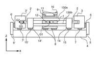
図3は本発明にかかる第3実施形態の位置決め装置の構成を説明する正面図であり、その平面図は図2(a)と同一である。図3において、図1及び図2と同じ構成要素は同一の参照番号を付している。本実施形態は、第2実施形態に対して、Yビームを上下2本で構成したところが異なっている。すなわち、130a,130bは上下二本で構成されたYビームであり、それらの両側面には移動テーブル1のX方向の移動をガイドするXガイド面が構成されており、このガイド面と、移動テーブル1との間には、図示しない静圧軸受が配置され、非接触により直動ガイド動作を行なっている。
【0067】
本実施形態では、Xビーム12を1本、Yビーム130a,130bを上下に配置した2本で構成しているので、Xビーム12とXスライダー16,16’及びXリニアモーター可動子17,17’とから構成される単X軸移動体の重心高さと、Yビーム130a,130bとYスライダー14,14’及びYリニアモーター可動子2,2’とから構成される単Y軸移動体の重心高さを略一致させることが、設計的により容易になる。
【0068】
あるいは、本実施形態ではXビーム12を1本、Yビーム130a,130bを上下に配置した2本で構成しているので、Xビーム12の側面部に構成されるYガイド面の図心高さと、Yビーム130a,130bの側面部で構成されるXガイド面の図心高さを一致させることができる。これら両ガイド面の図心高さは、Xビーム12およびYビーム130a,130bのX方向及びY方向の駆動力を、それぞれ移動テーブル1に伝達する時の力の作用線の高さに相当し、移動テーブル1の重心高さと、この図心の高さとの差が、移動テーブル1に加えられるモーメントになる。
【0069】
従って、Xビーム12の側面部に構成されるYガイド面(12a,12b)の図心高さと、Yビーム130a,130bの側面で構成されるXガイド面の図心高さが同じなので、移動テーブル1のX方向の駆動とY方向の駆動とで与えられるモーメントが等しくなり、振動収束時間や最大ピッチング量などの動的な挙動をほぼ等しくすることだができる。
【0070】
また、Xガイド面及びYガイド面の図心の高さと、移動テーブル1,微動テーブル9,反射ミラー11及び微動アクチュエーター11とから構成される移動体全体の重心高さとを一致させることで、移動体全体の重心に各リニアモーター推力の伝達力が作用することになるので、その重心回りのモーメントを発生させないことになり、ステージ定盤1に対する振動を励起することが避けられる。
【0071】
さらに、Xビーム12とXスライダー16,16’とXリニアモーター可動子17,17’とから構成されるX移動体の重心高さと、Yビーム130a,130bとYスライダー14,14’とYリニアモーター可動子2,2’とから構成されるY移動体の重心高さ、及び、各リニアモーター固定子の推力作用線を一致させることが望ましい。これにより、これらX移動体及びY移動体の単体の駆動においても、その重心回りのモーメントが一切発生しないので、ステージ定盤4に対する振動を励起することが避けられる。
【0072】
本実施形態は、Yビームを上下2本、Xビームを1本で構成した例について説明したが、逆にXビームを上下2本、Yビームを1本で構成しても全く同一の効果が得られる。さらに、ビーム数を2本に限定するものではなく、3本以上の複数としてもよく、片方をあえて一本に限定する必要も無く、複数本同士であってもよい。片方を偶数本、他方を奇数本とすることができ、例えば片方を2本とし他方を3本としてビームを構成することも可能である。
【0073】
<第4実施形態(露光装置)>
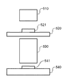
図8は、上記の位置決め装置を基板ステージ及び/または原版ステージとして組み込んだ露光装置の概略構成を示す図である。この露光装置は、原版ステージ520に保持された原版(レチクル、マスク)521を照明光学系510により照明し、原版521のパターンを投影光学系530を介して基板ステージ(ウエハステージ)540上の基板(ウエハ)541に投影し基板541を露光する。ここで、各ステージ520、540は、第1〜第3実施形態のいずれかにおいて説明した位置決め装置が適用されている。
【0074】
上述の実施形態にかかる位置決め装置を組み込んだ露光装置によれば、移動テーブルの加減速の際に発生する駆動反力を、モーターの固定子を逆方向に移動させることによって運動エネルギーに変換して吸収し、同時に各移動部分の重心位置の高さを略一致させた構造により、モーメント反力によってステージ定盤に加わる励振をキヤンセルできるので、駆動反力及びモーメントに起因する定盤の揺れや振動が抑制でき、高速かつ高精度な位置決め、露光が可能になる。高速かつ高精度な位置決め装置を採用することにより露光装置のスループットの向上を図ることが可能になる。
【0075】
<第5実施形態(半導体製造プロセス)>
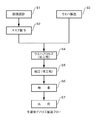
次に、上記の露光装置を利用した半導体デバイスの製造プロセスを説明する。図6は半導体デバイスの全体的な製造プロセスのフローを示す図である。ステップ1(回路設計)では半導体デバイスの回路設計を行なう。ステップ2(マスク作製)では設計した回路パターンに基づいてマスクを作製する。
【0076】
一方、ステップ3(ウエハ製造)ではシリコン等の材料を用いてウエハを製造する。ステップ4(ウエハプロセス)は前工程と呼ばれ、上記のマスクとウエハを用いて、上記の露光装置によりリソグラフィ技術を利用してウエハ上に実際の回路を形成する。次のステップ5(組み立て)は後工程と呼ばれ、ステップ4によって作製されたウエハを用いて半導体チップ化する工程であり、アッセンブリ工程(ダイシング、ボンディング)、パッケージング工程(チップ封入)等の組み立て工程を含む。ステップ6(検査)ではステップ5で作製された半導体デバイスの動作確認テスト、耐久性テスト等の検査を行なう。こうした工程を経て半導体デバイスが完成し、これを出荷(ステップ7)する。
【0077】
上記ステップ4のウエハプロセスは以下のステップを有する。ウエハの表面を酸化させる酸化ステップ、ウエハ表面に絶縁膜を成膜するCVDステップ、ウエハ上に電極を蒸着によって形成する電極形成ステップ、ウエハにイオンを打ち込むイオン打ち込みステップ、ウエハに感光剤を塗布するレジスト処理ステップ、上記の露光装置によって回路パターンをレジスト処理ステップ後のウエハに転写する露光ステップ、露光ステップで露光したウエハを現像する現像ステップ、現像ステップで現像したレジスト像以外の部分を削り取るエッチングステップ、エッチングが済んで不要となったレジストを取り除くレジスト剥離ステップ。これらのステップを繰り返し行なうことによって、ウエハ上に多重に回路パターンを形成する。
【0078】
【発明の効果】
以上、本発明によれば、移動テーブルの重心高さと、リニアモータ固定子の重心高さ、リニアモータ作用線の高さを一致させることにより、モーメント反力の発生を防ぐことが可能になり、ステージ定盤の揺れや振動を励起することがない、高速かつ高精度な位置決め装置の実現が可能になる。
【図面の簡単な説明】
【図1】第1実施形態の位置決め装置の構成を説明する図である。
【図2】第2実施形態の位置決め装置の構成を説明する図である。
【図3】第3実施形態の位置決め装置の構成を説明する図である。
【図4】重心位置の不一致により生じるモーメント反力を説明する図である。
【図5】実施形態にかかる位置決め装置を適用した露光装置の概略的な構成を説明する図である。
【図6】半導体デバイスの全体的な製造プロセスのフローを示す図である。
【符号の説明】
1 移動テーブル
2、2’ Yリニアモーター可動子
3、3’ Yリニアモーター固定子
4 ステージ定盤
5、5’ Yヨーイングガイド
6、6’ 静圧軸受
9 微動テーブル
10 反射ミラー
11 微動アクチュエーター
12 Xビーム
13 Yビーム
14、14’ Yスライダー
16、16’ Xスライダー
17、17’ Xリニアモーター可動子
18、18’ Xリニアモーター固定子
20、20’ Xヨーガイド[0001]
TECHNICAL FIELD OF THE INVENTION
The present invention relates to a positioning apparatus suitably used for high-precision processing such as a semiconductor lithography process.
[0002]
[Prior art]
2. Description of the Related Art Conventionally, as an exposure apparatus used for manufacturing a semiconductor device or the like, a pattern of an original (reticle or mask) is projected onto a plurality of exposure regions on a substrate through a projection optical system while a substrate (wafer or glass substrate) is step-moved. A step-and-repeat type exposure apparatus (also referred to as a “stepper”) for sequentially exposing, or a step-and-repeat type that repeats exposure transfer to a plurality of regions on a substrate by repeating step movement and scanning exposure. A scanning type exposure apparatus (sometimes called a “scanner”) is typical.
[0003]
In particular, the step-and-scan type uses only the part relatively close to the optical axis of the projection optical system, limited by the slit, so it is possible to expose fine patterns with higher precision and a wider angle of view. It has become.
[0004]
These exposure apparatuses have stage devices (wafer stage, reticle stage) for moving and positioning a wafer or a reticle at a high speed (for example, see Patent Document 1).
[0005]
[Patent Document 1]
JP-A-62-88526
[0006]
[Problems to be solved by the invention]
[0007]
Therefore, an object of the present invention is to provide a positioning device capable of reducing vibration and shaking caused by movement of a stage and performing high-speed, high-precision positioning, and an exposure device to which the positioning device is applied. . In particular, it is an object of the present invention to reduce vibration and shaking of a surface plate due to a moment reaction force generated by movement of a stage.
[0008]
[Means for Solving the Problems]
In order to solve the above problems and achieve the object, a positioning device, an exposure device, and the like according to the present invention are mainly characterized by having the following configurations.
[0009]
That is, a positioning device having a movable portion and a reaction force absorbing mechanism for absorbing a propulsion reaction force generated by the movement of the movable portion,
A first distance between a reference plane and a center of gravity of the movable portion movably supported on the reference plane and a second distance between the reference plane and the center of gravity of the reaction force absorbing mechanism are substantially the same; and And / or the third distance between the second distance and the motor mover for propelling the reference plane and the movable part into the reference plane is made substantially the same.
[0010]
Preferably, in the positioning device described above, the front base reaction force absorbing mechanism is a stator of a motor that drives the movable portion and is configured to be movable on the reference plane.
[0011]
Further, a positioning device having a movable portion movable in two axial directions substantially orthogonal to each other in a plane, and first and second reaction force absorbing mechanisms for absorbing a propulsion reaction force generated by movement of the movable portion in each axis direction is provided. ,
A fourth distance between a reference plane and the position of the center of gravity of the X moving body including the movable section movably supported on the reference plane;
A fifth distance between the reference plane and a position of the center of gravity of the first reaction force absorbing mechanism corresponding to a first movement direction of the X moving body is configured to be substantially the same distance,
A sixth distance between the reference plane, and the center of gravity of the Y moving body including the movable portion that is movably supported on the reference plane;
A seventh distance between the reference plane and the position of the center of gravity of the second reaction force absorbing mechanism corresponding to the second movement direction of the Y moving body is configured to be substantially the same. .
[0012]
Preferably, in the positioning device described above, the X movable body includes the movable part, a second movable part formed on the movable part, and a propulsive force for propelling the movable body in a first direction. A first beam member for transmitting to the body, a first guide member for guiding the movement of the movable part in a first direction, and a first motor movable element for propelling the movable part in the first direction. Including.
[0013]
Preferably, in the positioning device described above, the Y movable body includes the movable part, a second movable part configured on the movable part, and a propulsive force for propelling the movable body in a second direction. A second beam member for transmitting to the body, a second guide member for guiding the movement of the movable portion in a second direction, and a second motor movable element for propelling the movable portion in the second direction. Including.
[0014]
Preferably, in the positioning device described above, the second movable section is a fine movement stage for adjusting a position and a posture of the movable section.
[0015]
Preferably, in the positioning device described above, the X moving body includes a first beam member that transmits a propulsive force for propelling the movable body in a first direction to the movable body, and guides the movement in the first direction. And a first motor mover for propelling the movable portion in a first direction.
[0016]
Preferably, in the positioning device described above, the Y moving body includes a second beam member that transmits a propulsive force for propelling the movable body in the second direction to the movable body, and guides movement in the second direction. And a second motor mover for propelling the movable portion in the second direction.
[0017]
Further, a positioning device having a movable portion movable in two axial directions substantially orthogonal to each other in a plane, and first and second reaction force absorbing mechanisms for absorbing a propulsion reaction force generated by movement of the movable portion in each axis direction is provided. ,
An eighth distance between a reference plane, and a center of gravity position of a first guide member that guides the movable portion movably supported on the reference plane in a first direction;
A ninth distance between the reference plane and the position of the center of gravity of the first reaction force absorbing mechanism corresponding to a first movement direction of the movable unit is configured to be substantially the same distance,
A tenth distance between the reference plane, and a center of gravity of a second guide member that guides the movable portion supported movably on the reference plane in a second direction;
An eleventh distance between the reference plane and the position of the center of gravity of the second reaction force absorbing mechanism corresponding to the second movement direction of the movable portion is configured to be substantially the same distance.
[0018]
Further, a positioning device having a movable portion movable in two axial directions substantially orthogonal to each other in a plane, and first and second reaction force absorbing mechanisms for absorbing a propulsion reaction force generated by movement of the movable portion in each axis direction is provided. ,
A twelfth distance between a reference plane and a first motor mover for propelling the movable part in a first direction within the reference plane;
A thirteenth distance between the reference plane and the position of the center of gravity of the first reaction force absorbing mechanism corresponding to the first movement direction of the movable part is configured to be substantially the same distance,
A fourteenth distance between the reference plane and a second motor mover for propelling the movable part in a second direction within the reference plane;
The fifteenth distance between the reference plane and the position of the center of gravity of the second reaction force absorbing mechanism corresponding to the second movement direction of the movable part is configured to be substantially the same distance.
[0019]
Preferably, in the above positioning device, the eighth distance and the twelfth distance are configured to be substantially the same distance.
[0020]
Preferably, in the above positioning device, the tenth distance and the fourteenth distance are configured to be substantially the same distance.
[0021]
Preferably, in the positioning device described above, the first guide member and / or the second guide member that guide the movement of the movable portion in each movement direction are arranged in a plurality in a direction separated from the reference plane. Of guide members.
[0022]
Preferably, in the positioning device described above, the front base first and second reaction force absorbing mechanisms are motor stators configured to be movable on the reference plane and to drive the movable unit.
[0023]
The exposure apparatus is
An original plate positioning device that holds the original plate, drives it to a predetermined position, and positions it at a predetermined position;
A substrate positioning device that holds the substrate, drives it to a predetermined position, and positions the substrate at a predetermined position;
A projection optical system for projecting an original pattern onto the substrate,
Including
The reticle positioning device and / or the substrate positioning device have a configuration of the above-described positioning device.
[0024]
Also, the device manufacturing method
Applying a photosensitive agent to the substrate;
Exposing the substrate by the exposure apparatus described above,
Developing the substrate;
It is characterized by including.
[0025]
BEST MODE FOR CARRYING OUT THE INVENTION
Hereinafter, embodiments according to the present invention will be described with reference to the drawings.
[0026]
<First embodiment>
<Configuration of positioning device>
FIGS. 1A and 1B are diagrams illustrating a configuration of a positioning device according to a first embodiment of the present invention. FIG. 1A is a plan view of the positioning device, and FIG. In the figure,
[0027]
[0028]
The moving table 1 is supported by a static pressure bearing 8 in a non-contact manner with respect to the stage base 4 (FIG. 1B), and is movable in the Y direction. On both sides of the moving table 1, Y
[0029]
Here, the Y
[0030]
The Y
[0031]
That is, by moving the Y
[0032]
In the present embodiment, for example, when the moving table 1 is driven in the + Y direction, the Y
[0033]
In the positioning apparatus, in order to position the moving table at a predetermined position, one or more laser interferometers (not shown) are provided, and the position of the moving table is controlled based on position information detected by the laser interferometer. It is also possible to measure the position of the stator using an interferometer (not shown) to position the Y
[0034]
According to the configuration shown in FIGS. 1A and 1B, the Y
[0035]
Further, since the Y
According to the present embodiment, since the Y
[0036]
Further, according to the present embodiment, the Y
[0037]
1 (a) and 1 (b), the driving reaction force generated when the moving table 1 is accelerated or decelerated is reduced by the Y
[0038]
<Moment absorption around the center of gravity>
However, when the height of the center of gravity of the moving table 1 does not match the height of the center of gravity of the stator Y linear motor, it is necessary to consider the moment around the center of gravity of the structure including the stage base. That is, the moment about the x axis applied to the entire apparatus by the movement of the moving table 1 and the moment about the x axis applied to the entire apparatus by the movement of the Y
[0039]
For example, as shown in FIG. 4, the center of gravity G1 of the moving table 1 (the height in the Z direction with reference to the upper surface of the stage base 4) is higher than the center of gravity G2 of the Y
[0040]
On the other hand, the Y
[0041]
It is obvious that the moment of the former having a higher center of gravity is larger if the acting forces are equal, so that the moment in the −ωX direction is predominantly applied to the
[0042]
The configuration of the positioning device according to the present embodiment (FIGS. 1A and 1B) includes a Y
[0043]
<Line of action of linear motor>
Further, in the present embodiment, as shown in FIG. 1B, the height (G3) of the line of action of the force applied to the Y linear motor mover is also the height of the center of gravity of the Y
[0044]
With the above configuration, the driving reaction force in the Y-axis direction, which is the moving direction of the moving table 1, is absorbed by the movement of the stator, and the height of the center of gravity (G1) of the moving table 1 and the
[0045]
In the present embodiment, the guide surface of the moving table 1 and the guide surfaces of the Y
[0046]
<Second embodiment>
FIGS. 2A and 2B are diagrams illustrating a configuration of a positioning device according to a second embodiment of the present invention, wherein FIG. 2A is a plan view of the positioning device, and FIG. 2B is a front view thereof. In the figure, the same components as those in FIG. 1 are denoted by the same reference numerals.
[0047]
[0048]
[0049]
[0050]
The moving table 1 is supported by a static pressure bearing 8 in a non-contact manner with respect to the stage base 4 (see FIG. 2B), and is movable in the XY directions. An
[0051]
[0052]
X
[0053]
Here, the X
[0054]
<Driving reaction force absorption>
The X
[0055]
By driving the moving table 1 in the X direction and the Y direction by the thrust of each linear motor, the X
[0056]
Due to the driving reaction force, the X
[0057]
For example, when the moving table 1 is driven in the + X direction, the X
[0058]
<Moment absorption around the center of gravity>
However, also as described in the first embodiment, the influence of the moment due to the mismatch of the height of the center of gravity of the moving table and the combination thereof becomes a problem. For example, assuming that the moving table 1 is moved in the X direction, the moving table 1, the fine moving table 9, the reflecting
[0059]
Also, when moving in the Y direction, the moving table 1, the fine moving table 9, the reflecting
[0060]
In the present embodiment, in order to eliminate the influence of the above-mentioned moment reaction force, the height of the center of gravity of the entire X-direction moving body and the height of the center of gravity of the X
[0061]
Further, in the present embodiment, the height of the center of gravity of a moving body (hereinafter, referred to as a “single X-axis moving body”) including the
[0062]
<Line of action of linear motor>
Furthermore, in the present embodiment, as shown in FIG. 1, it is desirable that the height of the line of action of the force applied to each linear motor mover also coincides with the height of the center of gravity of each linear motor stator. As a result, the linear motor thrust acts on the height of the center of gravity of each linear motor stator, so that the X
[0063]
With the above configuration, as a result, not only reaction forces in the X-axis and Y-axis directions, which are the moving directions of the moving table 1, but also respective moments about the x-axis, the Y-axis, and the z-axis are generated on the stage base. Thus, a stage device that does not excite the shaking or vibration of the
[0064]
With the above configuration, the driving reaction force generated by the movement of the moving table 1 is absorbed by the movement of the stator, and the height of the center of gravity of the moving body, the height of the center of gravity of the linear motor stator, and the linear motor action line (G3) By making the heights of the positioning plate coincide with each other, it is possible to prevent the generation of a moment around the x-axis and a moment reaction force around the z-axis. Realization becomes possible.
[0065]
In the present embodiment, the guide surface of the moving table 1 and the guide surfaces of the Y
[0066]
<Third embodiment>
FIG. 3 is a front view illustrating the configuration of a positioning device according to a third embodiment of the present invention, and its plan view is the same as FIG. 2A. 3, the same components as those in FIGS. 1 and 2 are denoted by the same reference numerals. This embodiment is different from the second embodiment in that the upper and lower Y beams are configured. In other words, 130a and 130b are Y beams composed of two upper and lower beams, and on both side surfaces thereof, an X guide surface for guiding the movement of the moving table 1 in the X direction is configured. A static pressure bearing (not shown) is arranged between the table and the table 1, and performs a linear motion guide operation in a non-contact manner.
[0067]
In this embodiment, since the
[0068]
Alternatively, in the present embodiment, since one
[0069]
Therefore, since the centroid height of the Y guide surfaces (12a, 12b) formed on the side surface portion of the
[0070]
In addition, the height of the centroids of the X guide surface and the Y guide surface is matched with the height of the center of gravity of the entire moving body including the moving table 1, the fine moving table 9, the reflecting
[0071]
Further, the height of the center of gravity of the X moving body composed of the
[0072]
Although the present embodiment has been described with respect to an example in which the Y beam is composed of two upper and lower beams and the X beam is composed of one beam, the same effect can be obtained even if the X beam is composed of two upper and lower beams and one Y beam. can get. Further, the number of beams is not limited to two, but may be three or more. The number of beams need not be limited to one, and a plurality of beams may be used. One may be an even number and the other may be an odd number. For example, it is also possible to configure a beam with one being two and the other being three.
[0073]
<Fourth embodiment (exposure apparatus)>
FIG. 8 is a diagram showing a schematic configuration of an exposure apparatus in which the above-described positioning apparatus is incorporated as a substrate stage and / or an original stage. This exposure apparatus illuminates an original (reticle, mask) 521 held on an
[0074]
According to the exposure apparatus incorporating the positioning device according to the above-described embodiment, the driving reaction force generated when the moving table is accelerated or decelerated is converted into kinetic energy by moving the stator of the motor in the opposite direction. The structure that absorbs and at the same time, the height of the center of gravity of each moving part is almost the same makes it possible to cancel the excitation applied to the stage base by the moment reaction force, so that the base plate shakes and vibrates due to the driving reaction force and moment And high-speed and high-precision positioning and exposure can be performed. By employing a high-speed and high-precision positioning device, it is possible to improve the throughput of the exposure apparatus.
[0075]
<Fifth Embodiment (Semiconductor Manufacturing Process)>
Next, a manufacturing process of a semiconductor device using the above exposure apparatus will be described. FIG. 6 is a diagram showing a flow of the entire semiconductor device manufacturing process. In step 1 (circuit design), the circuit of the semiconductor device is designed. In step 2 (mask fabrication), a mask is fabricated based on the designed circuit pattern.
[0076]
On the other hand, in step 3 (wafer manufacturing), a wafer is manufactured using a material such as silicon. Step 4 (wafer process) is referred to as a preprocess, and an actual circuit is formed on the wafer by using the lithography technique by the above-described exposure apparatus using the above-described mask and wafer. The next step 5 (assembly) is called a post-process, and is a process of forming a semiconductor chip using the wafer prepared in
[0077]
The wafer process in
[0078]
【The invention's effect】
As described above, according to the present invention, the height of the center of gravity of the moving table, the height of the center of gravity of the linear motor stator, and the height of the line of action of the linear motor can be matched to prevent the occurrence of moment reaction force, A high-speed and high-precision positioning device that does not excite the shake and vibration of the stage base can be realized.
[Brief description of the drawings]
FIG. 1 is a diagram illustrating a configuration of a positioning device according to a first embodiment.
FIG. 2 is a diagram illustrating a configuration of a positioning device according to a second embodiment.
FIG. 3 is a diagram illustrating a configuration of a positioning device according to a third embodiment.
FIG. 4 is a diagram for explaining a moment reaction force generated by a mismatch between the positions of the centers of gravity.
FIG. 5 is a diagram illustrating a schematic configuration of an exposure apparatus to which the positioning device according to the embodiment is applied.
FIG. 6 is a diagram showing a flow of an overall semiconductor device manufacturing process.
[Explanation of symbols]
1 moving table
2,2 'Y linear motor mover
3, 3 'Y linear motor stator
4 Stage surface plate
5, 5 'Y yawing guide
6, 6 'hydrostatic bearing
9 Fine movement table
10 Reflection mirror
11 Fine movement actuator
12 X beam
13 Y beam
14, 14 'Y slider
16, 16 'X slider
17, 17 'X linear motor mover
18, 18 'X linear motor stator
20, 20 'X-Yaw guide
Claims (1)
基準面と該基準面上を移動可能に支持されている可動部の重心位置の間の第1距離と前記基準面と前記反力吸収機構の重心位置の間の第2距離を略同一、および/または、前記第2距離と前記基準面と前記可動部を該基準面内に推進させるためのモーター可動子の間の第3距離を略同一にしていることを特徴とする位置決め装置。In a positioning device having a movable portion and a reaction force absorbing mechanism for absorbing a propulsion reaction force generated by the movement of the movable portion,
A first distance between a reference plane and a center of gravity of the movable portion movably supported on the reference plane and a second distance between the reference plane and the center of gravity of the reaction force absorbing mechanism are substantially the same; and And / or a third distance between the second distance and a motor movable element for propelling the reference plane and the movable portion into the reference plane is substantially the same.
Priority Applications (2)
| Application Number | Priority Date | Filing Date | Title |
|---|---|---|---|
| JP2002314926A JP2004152902A (en) | 2002-10-29 | 2002-10-29 | Positioning device |
| US10/694,083 US6965426B2 (en) | 2002-10-29 | 2003-10-28 | Positioning system and exposure apparatus having the same |
Applications Claiming Priority (1)
| Application Number | Priority Date | Filing Date | Title |
|---|---|---|---|
| JP2002314926A JP2004152902A (en) | 2002-10-29 | 2002-10-29 | Positioning device |
Publications (2)
| Publication Number | Publication Date |
|---|---|
| JP2004152902A true JP2004152902A (en) | 2004-05-27 |
| JP2004152902A5 JP2004152902A5 (en) | 2005-09-22 |
Family
ID=32459107
Family Applications (1)
| Application Number | Title | Priority Date | Filing Date |
|---|---|---|---|
| JP2002314926A Pending JP2004152902A (en) | 2002-10-29 | 2002-10-29 | Positioning device |
Country Status (2)
| Country | Link |
|---|---|
| US (1) | US6965426B2 (en) |
| JP (1) | JP2004152902A (en) |
Families Citing this family (6)
| Publication number | Priority date | Publication date | Assignee | Title |
|---|---|---|---|---|
| US7221433B2 (en) * | 2004-01-28 | 2007-05-22 | Nikon Corporation | Stage assembly including a reaction assembly having a connector assembly |
| JP2005268268A (en) * | 2004-03-16 | 2005-09-29 | Canon Inc | Electron beam exposure system |
| JP4617119B2 (en) * | 2004-08-30 | 2011-01-19 | キヤノン株式会社 | Drive apparatus, exposure apparatus, and device manufacturing method |
| US7456935B2 (en) * | 2005-04-05 | 2008-11-25 | Asml Netherlands B.V. | Lithographic apparatus and device manufacturing method utilizing a positioning device for positioning an object table |
| US20070152391A1 (en) * | 2005-12-29 | 2007-07-05 | Chitayat Anwar K | Error corrected positioning stage |
| CN110868007B (en) * | 2019-11-27 | 2020-12-01 | 大连佳峰自动化股份有限公司 | Damping mechanism of linear motor |
Family Cites Families (5)
| Publication number | Priority date | Publication date | Assignee | Title |
|---|---|---|---|---|
| JPH066248B2 (en) | 1985-10-14 | 1994-01-26 | オムロン株式会社 | XY stage |
| US6151100A (en) * | 1996-12-12 | 2000-11-21 | Canon Kabushiki Kaisha | Positioning system |
| JP3810039B2 (en) * | 1998-05-06 | 2006-08-16 | キヤノン株式会社 | Stage equipment |
| TW546551B (en) * | 1999-12-21 | 2003-08-11 | Asml Netherlands Bv | Balanced positioning system for use in lithographic apparatus |
| US6958808B2 (en) * | 2000-11-16 | 2005-10-25 | Nikon Corporation | System and method for resetting a reaction mass assembly of a stage assembly |
-
2002
- 2002-10-29 JP JP2002314926A patent/JP2004152902A/en active Pending
-
2003
- 2003-10-28 US US10/694,083 patent/US6965426B2/en not_active Expired - Fee Related
Also Published As
| Publication number | Publication date |
|---|---|
| US20040145715A1 (en) | 2004-07-29 |
| US6965426B2 (en) | 2005-11-15 |
Similar Documents
| Publication | Publication Date | Title |
|---|---|---|
| KR100573669B1 (en) | Balanced positioning system for lithographic apparatus | |
| US8009275B2 (en) | Movable stage apparatus | |
| US7586218B2 (en) | Moving apparatus, exposure apparatus, and device manufacturing method | |
| JP3963410B2 (en) | Positioning apparatus and exposure apparatus using the same | |
| CN105493237B (en) | Moving body apparatus, exposure apparatus, and device manufacturing method | |
| US6891597B2 (en) | Driving apparatus, exposure apparatus, and device manufacturing method | |
| US6320645B1 (en) | Stage system and exposure apparatus, and device manufacturing method using the same | |
| EP1111469A2 (en) | Lithographic apparatus with a balanced positioning system | |
| JP2004152902A (en) | Positioning device | |
| JP3919782B2 (en) | Exposure apparatus and device manufacturing method | |
| JP2001023896A (en) | Stage device and exposure device | |
| JPH10149974A (en) | Stage apparatus, exposure apparatus, and device manufacturing method | |
| JP2001230178A (en) | Positioning apparatus, exposure apparatus, and device manufacturing method | |
| JP2004111653A (en) | Positioning apparatus, exposure apparatus and semiconductor device manufacturing method using the same | |
| JP4011919B2 (en) | Moving apparatus, exposure apparatus, and semiconductor device manufacturing method | |
| JP4208914B2 (en) | Exposure apparatus, device manufacturing method using the same, and stage apparatus | |
| JPH11297613A (en) | Stage apparatus, exposure apparatus using the same, and device manufacturing method | |
| JP2001230177A (en) | Positioning apparatus, exposure apparatus, and device manufacturing method | |
| JP2000352592A (en) | Stage apparatus, exposure apparatus using the same, and device manufacturing method |
Legal Events
| Date | Code | Title | Description |
|---|---|---|---|
| A521 | Written amendment |
Free format text: JAPANESE INTERMEDIATE CODE: A523 Effective date: 20050407 |
|
| A621 | Written request for application examination |
Free format text: JAPANESE INTERMEDIATE CODE: A621 Effective date: 20050407 |
|
| A977 | Report on retrieval |
Free format text: JAPANESE INTERMEDIATE CODE: A971007 Effective date: 20060609 |
|
| A131 | Notification of reasons for refusal |
Free format text: JAPANESE INTERMEDIATE CODE: A131 Effective date: 20060623 |
|
| A521 | Written amendment |
Free format text: JAPANESE INTERMEDIATE CODE: A523 Effective date: 20060822 |
|
| A131 | Notification of reasons for refusal |
Free format text: JAPANESE INTERMEDIATE CODE: A131 Effective date: 20071122 |
|
| A02 | Decision of refusal |
Free format text: JAPANESE INTERMEDIATE CODE: A02 Effective date: 20080404 |