JP2004155009A - Printing condition setting method and printing device - Google Patents
Printing condition setting method and printing device Download PDFInfo
- Publication number
- JP2004155009A JP2004155009A JP2002322049A JP2002322049A JP2004155009A JP 2004155009 A JP2004155009 A JP 2004155009A JP 2002322049 A JP2002322049 A JP 2002322049A JP 2002322049 A JP2002322049 A JP 2002322049A JP 2004155009 A JP2004155009 A JP 2004155009A
- Authority
- JP
- Japan
- Prior art keywords
- printing
- sheet
- setting
- continuous paper
- cut sheet
- Prior art date
- Legal status (The legal status is an assumption and is not a legal conclusion. Google has not performed a legal analysis and makes no representation as to the accuracy of the status listed.)
- Granted
Links
Images


Landscapes
- Delivering By Means Of Belts And Rollers (AREA)
- Facsimiles In General (AREA)
- Handling Of Sheets (AREA)
- Accessory Devices And Overall Control Thereof (AREA)
- Controlling Sheets Or Webs (AREA)
Abstract
Description
【0001】
【発明の属する技術分野】
本発明は印字条件の設定方法および印字装置に関する。
【0002】
【従来の技術】
プリンタには、複数種の記録媒体(用紙等の被記録媒体、インクリボン等の転写媒体)や、接続する機器(パソコンや携帯端末等のホスト装置やキーボード、スキャナ等の入力装置等)に対応して最適な印字をするため、使用に際して設定しなけらばならない印字条件が多数存在する。
【0003】
特に携帯可能な小型プリンタでは、これと接続して使用する機器が度々変更される可能性があり、通信速度やインタフェースの選択などを頻繁に設定しなければならない場合が生じる。
【0004】
このため、プリンタのカバー内等にディップスイッチを設け、これを切り替えて印字条件を設定するものが知られている。
【0005】
然るに、ディップスイッチは各スイッチのON−OFF状態の組み合わせで設定を行うものであるため、設定内容が判りにくく、更に操作にドライバ等の工具が必要であるという問題があった。
【0006】
一方で、プリンタ本体に設けた表示画面を確認しながらテンキーやカーソル(矢印)キーを操作して設定を行うものが知られている。然るに、外部機器に接続するのを前提としたプリンタでは、キーボード等の入力装置や表示装置が簡略化されているため操作が困難であり、特に英字やカタカナしか表示できない液晶画面に初期画面を表示して階層的にモードを切り替えて設定するメニュー形式では、個々の入力操作に加え、現在操作中のモードが途中で別モードに切り替わっても判りにくいという欠点があった。
【0007】
そして、マニュアルに記録したバーコードをバーコードリーダーで読み取ることにより、一般ユーザー向けに操作を簡単にしたプリンタープロセッサーが特許文献1等により知られている。。
【0008】
【特許文献1】
特開平10−161249号公報
【0009】
【発明が解決しようとする課題】
然るに、上記特許文献1で知られた技術では、バーコードが記録されたマニュアルを常時プリンタと一緒に携えていなければプリンタを操作することができないという問題があった。
【0010】
本発明は上記従来技術の問題に鑑みなされたものであって、本発明の目的は、自ずから入力シートを作成し、これに印字条件を記録して光学的センサで読み取らせることにより、操作者が簡単に操作できるようにした印字条件の設定方法およびこの方法を実施するための印字装置を提供することにある。
【0011】
【課題を解決するための手段】
上記課題を解決するため、請求項1に記載の印字条件の設定方法が採用する手段は、連続紙および単票紙に印字可能な印字装置で印字条件の設定開始操作に従って連続紙に設定シートを印字して印字装置外に排出する行程と、前記設定シートに印字条件を記録する行程と、記録済み設定シートを印字装置に挿入する行程と、該設定シートを搬送しながら印字装置に設けた光学的センサで読み取る行程と、この読み取り結果に従い印字装置の印字条件を設定する行程と、新しく設定された印字条件でテスト印字を行う行程と、テスト印字が良好でなかった場合に再度連続紙から設定シートを印字して排出する行程とを備えたことを特徴とする。
【0012】
また、請求項2に記載の印字装置は、印字装置本体にセットされた連続紙を印字部に案内する連続紙案内路と、該連続紙案内路とは別に、印字装置本体外から挿入された単票紙を前記印字部に案内するように設けられた単票紙案内路と、前記連続紙案内路に設けられ、前記連続紙を印字部へ給送および印字部から後退させる第1の搬送手段と、前記単票紙案内路に設けられ、単票紙を印字部に給送する第2の搬送手段と、前記単票紙案内路に設けられ、単票紙が前記単票紙案内路に挿入されたことを検知する検知手段と、前記検知手段で単票紙が検知されると、その検知結果に基づいて前記単票紙が前記印字部に給送される前に印字部に既存する連続紙を後退させて印字部から退避させるように前記第1の搬送手段及び第2の搬送手段を制御する搬送制御手段と、印字条件の設定開始操作を行う設定開始手段と、印字条件の設定シートを搬送しながら読み取る光学的センサと、この読み取り結果に従い印字条件を設定し、新しく設定された印字条件でテスト印字を行い、印字条件の設定操作を終了するか再度連続紙から設定シートを印字して排出するかを選択する設定終了手段とを設けたことを特徴とする。
【0013】
【発明の実施の形態】
以下添付図面に従って本発明に係る印字条件の設定方法および印字装置の好ましい実施の形態例について詳説する。
【0014】
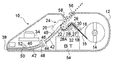
図1は、本発明に係る印字条件の設定方法を実施するための印字装置の断面図であり、バッテリー駆動が可能なポータブルプリンタ10(以下、単に「プリンタ」と記す)の例である。図1に示す如く、プリンタ10の外枠を形成するケーシング12内の一方側には供給リール14が回動自在に設けられ、該供給リール14にはロール状の連続紙15が巻回されている。また、供給リール14の近傍には、第1のフィードローラ16と該フィードローラ16に当接するピンチローラ18が設けられている。また、ケーシング12内の略中央には、サーマルヘッド20とプラテンローラ22からなる印字部24が設けられ、この印字部24と前記一対のローラ16、18との間には、上板26と下板28とから成る連続紙案内路30が形成されると共に、下板28の途中に形成された開口32を臨んで連続紙検知センサ27が設けられている。また、前記下板28はプラテンローラ22の下側周縁に沿って湾曲した湾曲部28Aを有し、連続紙15がサーマルヘッド20とプラテンローラ22との間に挿入され易くなっている。また、前記プラテンローラ22と第1のフィードローラ16は、図示しない正逆回転モータに連結されており、コントローラ(搬送制御手段)34からの指示により正逆回転される。また、連続紙検知センサ27は連続紙15の有無を検知し、その検知信号はコントローラ34に出力される。
【0015】
また、前記ケーシング12の供給リール14と反対側の側面には、単票紙36を挿入する挿入口38が形成されると共に、挿入口38と印字部24との間には、上板40と下板42から成る単票紙案内路44が設けられている。この単票紙案内路44は途中で分断されており、この分断位置に第2のフィードローラ46と、該第2のフィードローラ46に押圧する第2のピンチローラ48とが設けられている。この第2のフィードローラ46は図示しないモータに連結され、単票紙36を印字部24に給送するように回転する。また、挿入口38と前記一対のローラ46、48との間の上板40には、開口50が形成され、この開口50を臨んで単票紙検知センサ52が設けられている。そして、単票紙検知センサ52は、単票紙36の有無を検知し、その検知信号はコントローラ34に出力される。
【0016】
また、コントローラ34は、前記連続紙検知センサ27及び単票紙検知センサ52からの検知信号に基づいて、印字部24の印字動作、プラテンローラ22と第1のフィードローラ16の正逆回転、第2のフィードローラ46の回転を制御すると共に、これらの動作に必要な電源は、ケーシング12内に設けられたバッテリー54から供給される。また、印字部24上方のケーシング12の上面には、印字部24で印字された連続紙15又は単票紙36の排出口56が形成され、印字部24と排出口56との間には排出路58が形成されている。
【0017】
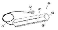
62は前記排出路58に臨んで形成されたスリット状のスキャナ取付部で、該スキャナ取付部62には図2に示すハンディスキャナ64(以下、単に「スキャナ」と記す)が着脱自在に取り付けられるようになっている。図2において、スキャナ本体66は略直方体の棒状をなし、読取面に沿って伸長する両側面には前記スキャナ取付部62に係合する係合溝68が形成され、図3に示す如くプリンタ10に取り付けられるようになっている。
【0018】
70はプリンタ10との接続を行うケーブルで、前記スキャナ本体66と反対側の先端にはコネクタ72が設けられている。
【0019】
前記スキャナ64は従来公知のスキャナと同様にプリンタ10からスキャナ本体66を離して画像をスキャンすることも、図3に示すようにプリンタ10に取り付けて排出路58を搬送されて通過する印字物の画像をスキャンして取り込むこともできるようになっている。
【0020】
次に、上記プリンタ10で連続紙15と単票紙36を切り替えて印字する方法を説明する。先ず、連続紙15に印字する場合を説明すると、供給リール14に装着したロール状の連続紙15の先端部を引き出して、第1のフィードローラ16と第1のピンチローラ18との間、及び連続用案内路30を通して連続紙検知センサ27まで手送りする。そして、連続紙検知センサ27が連続紙15の先端部を検知すると、その検知信号がコントローラ34に出力される。コントローラ34は、検知信号に基づいてプラテンローラ22及び第1のフィードローラ16を、連続紙15が印字部24に給送される回転方向に所定量回転させる。これにより、連続紙15は、連続紙案内路30に案内されて印字部24に給送され、サーマルヘッド20の印字開始位置で一旦停止し、印字準備が完了する。次に、コントローラ34からの印字情報がサーマルヘッド20に入力され、サーマルヘッド20から連続紙15に印字される共に、印字された連続紙15はサーマルヘッド20とプラテンローラ22により挟持搬送されて排出口56から排出される。この時、印字中の連続紙15の搬送には、第1のフィードローラ16は関与してもしなくてもよい。また、排出口56に排出された連続紙15は、印字の区切りの良い位置で図示しないカッターナイフ等で切断する。また、予め切断用のミシン目が入った連続紙15を使用してもよい。
【0021】
次に、単票紙36に印字する場合について説明する。この時、連続紙15は印字部24にセットされた状態にある。先ず、単票紙36を挿入口38から単票紙案内路44に挿入する。そして、単票紙検知センサ52が単票紙36の先端を検知すると、検知信号がコントローラ34に出力される。コントローラ34は検知信号に基づいて、先ず、プラテンローラ22と第1のフィードローラ16を、連続紙15が後退される回転方向に所定量回転させ、連続紙検知センサ27の手前まで連続紙15を後退させて連続紙15を印字部24から退避させる。この時、第1のピンチローラ18は第1のフィードローラ16の回転により連続紙15を介して従動回転する。そして、連続紙検知センサ27が連続紙15を検知しなくなると、その信号がコントローラ34に出力されてプラテンローラ22と第1のフィードローラ16の回転動作を停止する。次に、コントローラ34は、第2のフィードローラ46とプラテンローラ22を、単票紙36が印字部24に給送されるように所定量回転させる。この時、第2のピンチローラ48は第2のフィードローラ46の回転により単票紙34を介して従動回転する。これにより、単票紙36は単票紙案内路44に案内されて印字部24に給送され、サーマルヘッド20の印字開始位置で一旦停止し、印字準備が完了する。そして、連続紙15と同様にコントローラ34からの印字情報によりサーマルヘッドが作動して単票紙36に印字され、印字された単票紙36は排出口56から排出される。
【0022】
このように、プリンタ10では、単票紙36に印字する場合には、印字部24にセットされている連続紙15を後退させて、単票紙36が印字部24に給送される前に、連続紙15を印字部24から退避させるようにした。これにより、単票紙36が印字部24に給送される時には連続紙15が印字部24に存在しないので、単票紙36を印字部24にスムーズに給送することができる。また、印字中の単票紙36の搬送もスムーズになるので印字ズレ等の印字不良が発生しない。また、連続紙15と単票紙36とが印字部24に別々の案内路30、44を通って給送されるようにした。これにより、連続紙15の給送と印字部24から後退する搬送動作及び単票紙36を印字部24へ給送する搬送動作が互いに干渉せず、夫々の用紙15、36の搬送をスムーズに行うことができる。
【0023】
次に図4はプリンタ10の電気的構成を表すブロック図である。同図において、74はCPUであり、前記コントローラ34等を含めプリンタ10全体を制御する。
【0024】
75はROMであり、本実施の形態に係る印字条件設定処理を実現するための制御プログラムを格納する。ROM75に格納された制御プログラムはCPU74により実行される。
【0025】
76はRAMであり、CPU74が各種処理を実行する為の作業領域や補助記憶領域を提供する。
【0026】
77は記憶装置であり、スキャナ64で読み取った画像や印字情報を格納する。
【0027】
78は印字条件設定処理を開始/終了する操作ボタンで、該操作ボタン78は専用のスイッチ等を設けてもよいし、他の操作ボタンを兼用することもできる(例えば、フィードスイッチを押しながら電源スイッチ(いずれも図示せず)を押下する、フィードスイッチを押しながらオンラインスイッチを所定時間押下する、あるいはクリックする、など)。また、従来技術のようにメニュー形式から操作開始するようにしてもよい。
【0028】
次に、図5を用いて印字条件設定操作の方法を説明する。
電源の投入により装置が初期化され起動プログラムが読み込まれる。このとき、電源ボタンと共に操作ボタン78を押し続けることによりプリンタ設定モードとなる(S1)。
【0029】
プリンタ設定モードでは、連続紙36を用いて図6に示すようなプリンタ設定シート(マークシート)79を印字発行する(S2)。プリンタ10の操作者は、プリンタ設定シート79が印字された連続紙36を切り離して単票紙とし、筆記具を用いて各設定項目の選択肢(□)を塗りつぶす。
そして、記入済みのプリンタ設定シート79を単票紙の挿入口38から挿入する(S3)。なお、プリンタ設定モードでは、挿入口38から挿入された単票紙には印字部24による印字は行われない。
【0030】
次いで、スキャナ64から記入済みのマークシートを読み取り解析し(S4)、プリンタの印字条件を設定する(S5)。
そして、この設定された印字条件に従ってテスト印字および検証を行う(S6)。即ち、印字部24から連続紙36に図7のテストパターン80を印字し、これをスキャナ64で読み取る。
【0031】
次に、前記検証の結果、良好に読み取られたか否かを判定する(S7)。
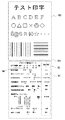
不良であれば(S7で「N」の場合)、現在の設定81が右端に記載された再設定用のプリンタ設定シート82をテスト印字に続けて連続紙36により印字出力する。尚、83は連続用紙36に予め形成された切り取り用のミシン目である。
【0032】
ここで、再設定用のマークシート82では、現在の設定81が右端に印字されるのと同時に、左側のマーク欄84には現在の設定の選択肢(□)を印字しないようにする。これにより、設定更新時に前回と同じ選択を繰り返す項目は記入不要にでき、重複した操作を省くことができる。
【0033】
そして、再設定用プリンタ設定シート82のみを切り離して、再度S3に戻り、単票紙の挿入口38に挿入して、テスト印字の検証が正常となるまで上記操作を繰り返す。
【0034】
前記S7で検証結果が正常となった場合(「Y」の場合)、操作ボタン78等の操作によって設定モードを終了するか否かの選択が可能となる(S9)。
これは、プリンタ10による検証の結果が良好であった場合でも、操作者等の目視による確認を可能とする為に設けられたステップである。ここで終了しない場合(「N」の場合)は、前記S8を経てS3にリターンする。
S9で終了する場合(「Y」の場合)は、上記の設定を保存して一連の処理を終了する。
【0035】
以上説明した通り、本実施の形態によれば、プリンタ自らが印字条件の設定用マークシートを印字発行し、記入後にこれをスキャナで読み込んで設定するようにしたから、ポータブルプリンタのように表示装置や入力装置が簡略化されたり省略されたプリンタであっても容易に印字条件を設定できる。
【0036】
また、プリンタ設定シートを単票紙の挿入口から挿入する時に、連続紙の先端を後退させるようにしたから、通紙を簡単にできるのと共にプリンタの紙詰まりも防止できる。
【0037】
また、印字条件の設定直後にテスト印字を行いこれを検証して読み取り不良であった場合に再度プリンタ設定シートを印字発行するので、良好な印字条件を素早く見つけることができる。
【0038】
特に、テスト印字と再設定用のシートを連続紙で発行し、再設定用のシートには現在の設定を可読文字で表示するのと共に、現在の設定を維持する項目については再記入不要なようにマーク欄を非表示にしたから、テスト印字と設定を比較して検討するのに都合良く、求める品質の印字を行うための条件を導くことが迅速に簡単かつ容易に行える。
【0039】
そして、テスト印字の検証は、スキャナを用いた検証と目視による検証を二重に行えるようにしたので、バーコード等の機械読み取りができればよいものと、人目に見て綺麗さが要求されるものとの両方に対応できる。
【0040】
尚、本発明は、上述した実施の形態にのみ限定されるものではなく、本発明の要旨を逸脱しない範囲内において種々変更を加えることができる。
【0041】
例えば、着脱自在なハンディスキャナをプリンタのケーシングに外部から固定して使用する例を示したが、スキャナはプリンタ内部に固定的に設置してもよい。
【0042】
また、電池駆動のポータブルプリンタでサーマル印字を行うものを例示したが、駆動電源や印字方式、大きさ等はどんなタイプの印字装置であってもよい。
【0043】
さらに、設定シートとしてマークシートの場合を例示したが、孔あけ位置を印字して指定したパンチカードのようなものであってもよい。
【0044】
【発明の効果】
以上詳述した通り、本発明によれば、プリンタ自らが印字条件の設定用シートを印字発行し、記入後にこれを光学的センサで読み込んで設定を行うので、表示装置や入力装置が簡略化または省略されたプリンタでも容易に印字条件を設定できる。
【0045】
また、プリンタ設定シートを単票紙の挿入口から挿入する時に、連続紙の先端を後退させるようにしたので、通紙を簡単にできるのと共にプリンタの紙詰まりを防止できる。
【0046】
また、印字条件の設定直後にテスト印字を行いこれを検証して読み取り不良であった場合に再度プリンタ設定シートを印字発行するようにしたから、良好な印字条件を素早く見つけることができ、テスト印字と再設定用のシートを連続紙で発行することにより、テスト印字と設定を比較して検討するのに都合良く、求める品質の印字条件を導くことが迅速に簡単かつ容易に行えるという優れた効果を奏する。
【図面の簡単な説明】
【図1】本発明の実施の形態に係るプリンタの断面図である。
【図2】スキャナの外観図である。
【図3】スキャナを取付け挿入口から単票紙を挿入した状態を示す図1と同様の断面図である。
【図4】実施の形態に係るプリンタの電気的構成を示すブロック図である。
【図5】印字設定処理を示すフロー図である。
【図6】プリンタ設定用シートの外観図である。
【図7】テスト印字と再設定用マークシートの外観図である。
【符号の説明】
10…ポータブルプリンタ、12…ケーシング、15…連続紙、38…挿入口、16…フィードローラ、18…ピンチローラ、20…サーマルヘッド、22…プラテンローラ、62…スキャナ取付部、64…スキャナ、79…プリンタ設定シート、80…テストパターン(テスト印字)、82…プリンタ設定シート(マークシート)[0001]
TECHNICAL FIELD OF THE INVENTION
The present invention relates to a printing condition setting method and a printing apparatus.
[0002]
[Prior art]
The printer supports multiple types of recording media (recorded media such as paper, transfer media such as ink ribbon) and connected devices (host devices such as personal computers and mobile terminals, keyboards, input devices such as scanners, etc.). There are many printing conditions that must be set for use in order to perform optimum printing.
[0003]
Particularly, in a portable small printer, there is a possibility that a device to be connected to the printer is frequently changed, and a communication speed, an interface selection, and the like must be frequently set.
[0004]
For this reason, there is known a printer in which a dip switch is provided in a cover of a printer or the like, and is switched to set a printing condition.
[0005]
However, since the DIP switches are set by a combination of ON / OFF states of the respective switches, there is a problem that the setting contents are difficult to understand and a tool such as a driver is required for operation.
[0006]
On the other hand, there has been known a printer which performs setting by operating a numeric keypad or a cursor (arrow) key while checking a display screen provided on a printer body. However, printers that are presumed to be connected to external devices are difficult to operate because input devices such as a keyboard and display devices are simplified, and the initial screen is displayed on an LCD screen that can only display English characters and katakana. In the menu format in which the mode is switched hierarchically and set, there is a disadvantage that it is difficult to recognize that the currently operated mode is switched to another mode on the way in addition to the individual input operations.
[0007]
A printer processor that has a barcode reader that reads a barcode recorded in a manual to simplify operation for general users is known from
[0008]
[Patent Document 1]
JP-A-10-161249
[Problems to be solved by the invention]
However, the technique disclosed in
[0010]
The present invention has been made in view of the above-described problems of the related art, and an object of the present invention is to create an input sheet by itself, record printing conditions on the input sheet, and read it with an optical sensor so that the operator can use the input sheet. It is an object of the present invention to provide a printing condition setting method which can be easily operated and a printing apparatus for performing the method.
[0011]
[Means for Solving the Problems]
In order to solve the above-mentioned problem, the means adopted by the method for setting printing conditions according to
[0012]
Further, in the printing apparatus according to the second aspect, a continuous paper guide path for guiding the continuous paper set in the printing apparatus main body to the printing section, and the continuous paper guide path is inserted separately from the outside of the printing apparatus main body. A cut sheet guide path provided to guide cut sheets to the printing section, and a first conveyance provided in the continuous sheet guide path for feeding the continuous sheet to the printing section and retreating from the printing section. Means, a second conveying means provided in the cut sheet guide path, for feeding cut sheets to a printing unit, and a cut sheet provided in the cut sheet guide path, wherein the cut sheet guide path is provided. Detection means for detecting that the cut sheet has been inserted, and when the cut sheet is detected by the detection means, the cut sheet is supplied to the printing section before being fed to the printing section based on the detection result. Controlling the first transporting means and the second transporting means so as to retreat the continuous paper to be retracted from the printing unit. Transport control means, a setting start means for performing an operation for starting the setting of printing conditions, an optical sensor for reading while conveying the sheet for setting the printing conditions, and a printing condition which is set in accordance with the read result, and the newly set printing conditions And a setting ending means for selecting whether to end the printing condition setting operation or to print and discharge the setting sheet from continuous paper again.
[0013]
BEST MODE FOR CARRYING OUT THE INVENTION
Hereinafter, preferred embodiments of a printing condition setting method and a printing apparatus according to the present invention will be described in detail with reference to the accompanying drawings.
[0014]
FIG. 1 is a cross-sectional view of a printing apparatus for carrying out a method for setting printing conditions according to the present invention, and is an example of a portable printer 10 (hereinafter simply referred to as “printer”) that can be driven by a battery. As shown in FIG. 1, a supply reel 14 is rotatably provided on one side in a casing 12 forming an outer frame of the
[0015]
On the side of the casing 12 opposite to the supply reel 14, an
[0016]
Further, based on detection signals from the continuous
[0017]
Reference numeral 62 denotes a slit-shaped scanner mounting portion formed facing the
[0018]
Reference numeral 70 denotes a cable for connecting to the
[0019]
The
[0020]
Next, a method of printing by switching between the
[0021]
Next, the case of printing on the cut sheet 36 will be described. At this time, the
[0022]
As described above, in the
[0023]
Next, FIG. 4 is a block diagram illustrating an electrical configuration of the
[0024]
A ROM 75 stores a control program for implementing the printing condition setting process according to the present embodiment. The control program stored in the ROM 75 is executed by the
[0025]
Reference numeral 76 denotes a RAM, which provides a work area and an auxiliary storage area for the
[0026]
[0027]
[0028]
Next, a printing condition setting operation method will be described with reference to FIG.
When the power is turned on, the device is initialized and the startup program is read. At this time, the printer setting mode is set by continuously pressing the
[0029]
In the printer setting mode, a printer setting sheet (mark sheet) 79 as shown in FIG. 6 is printed and issued using the continuous paper 36 (S2). The operator of the
Then, the completed printer setting sheet 79 is inserted through the cut-sheet insertion slot 38 (S3). In the printer setting mode, printing by the
[0030]
Next, the written mark sheet is read and analyzed from the scanner 64 (S4), and the printing conditions of the printer are set (S5).
Then, test printing and verification are performed according to the set printing conditions (S6). That is, the
[0031]
Next, as a result of the verification, it is determined whether or not the image has been successfully read (S7).
If it is defective ("N" in S7), the printer setting sheet 82 for resetting with the current setting 81 described on the right end is printed out on the continuous paper 36 following the test printing. 83 is a perforation for cutting formed in advance on the continuous paper 36.
[0032]
Here, in the resetting mark sheet 82, the current setting 81 is printed on the right end, and at the same time, the current setting option (□) is not printed on the left mark column 84. This eliminates the need to enter items that repeat the same selection as the previous one when updating the settings, and can eliminate duplicate operations.
[0033]
Then, only the printer setting sheet for resetting 82 is cut off, and the process returns to S3 again, is inserted into the
[0034]
If the verification result becomes normal in the above S7 (in the case of "Y"), it becomes possible to select whether to end the setting mode by operating the
This is a step provided to enable an operator or the like to visually check even if the result of the verification by the
If the process ends in S9 (in the case of “Y”), the above settings are saved and the series of processes ends.
[0035]
As described above, according to the present embodiment, the printer itself prints and issues a printing condition setting mark sheet, and after setting, reads and sets it with a scanner. The printing conditions can be easily set even with a printer in which the input device is simplified or omitted.
[0036]
Further, when the printer setting sheet is inserted through the cut sheet insertion slot, the leading end of the continuous paper is retracted, so that the paper can be easily passed and paper jam of the printer can be prevented.
[0037]
In addition, test printing is performed immediately after setting the printing conditions, and the test printing is verified. If a reading error occurs, the printer setting sheet is printed and issued again, so that good printing conditions can be quickly found.
[0038]
In particular, a sheet for test printing and resetting is issued on continuous paper, the current setting is displayed in readable characters on the resetting sheet, and items that maintain the current setting do not need to be re-entered. Since the mark column is not displayed, it is convenient to compare the test print with the setting, and it is possible to quickly, easily and easily derive the conditions for performing the print of the required quality.
[0039]
The test print verification can be performed in two ways: verification using a scanner and verification by visual inspection. And both.
[0040]
It should be noted that the present invention is not limited to the above-described embodiment, and various changes can be made without departing from the gist of the present invention.
[0041]
For example, while an example has been described in which a detachable handy scanner is used by being fixed to the casing of the printer from the outside, the scanner may be fixedly installed inside the printer.
[0042]
Also, a portable printer that is driven by a battery and performs thermal printing has been described as an example. However, any type of printing device may be used for the drive power supply, printing method, size, and the like.
[0043]
Furthermore, although the case of a mark sheet has been exemplified as the setting sheet, it may be a punch card in which a punching position is printed and specified.
[0044]
【The invention's effect】
As described in detail above, according to the present invention, the printer itself prints and issues a sheet for setting printing conditions, and after filling in, reads and sets the sheet with an optical sensor, so that the display device and the input device can be simplified or used. Even if the printer is omitted, the printing conditions can be easily set.
[0045]
Further, when the printer setting sheet is inserted from the cut sheet insertion slot, the leading end of the continuous paper is retracted, so that the paper passing can be simplified and the paper jam of the printer can be prevented.
[0046]
In addition, test printing is performed immediately after the printing conditions are set, and this is verified. If a reading error occurs, the printer setting sheet is printed again, so that good printing conditions can be found quickly and test printing can be performed. By issuing a sheet for re-setting with continuous paper, it is convenient to compare test printing and setting, and it is possible to quickly and easily and easily guide printing conditions of desired quality. To play.
[Brief description of the drawings]
FIG. 1 is a sectional view of a printer according to an embodiment of the present invention.
FIG. 2 is an external view of a scanner.
FIG. 3 is a cross-sectional view similar to FIG. 1, showing a state in which a cut sheet is inserted from an insertion slot with a scanner attached.
FIG. 4 is a block diagram illustrating an electrical configuration of the printer according to the embodiment.
FIG. 5 is a flowchart showing a print setting process.
FIG. 6 is an external view of a printer setting sheet.
FIG. 7 is an external view of a mark sheet for test printing and resetting.
[Explanation of symbols]
DESCRIPTION OF
Claims (2)
Priority Applications (1)
| Application Number | Priority Date | Filing Date | Title |
|---|---|---|---|
| JP2002322049A JP4266615B2 (en) | 2002-11-06 | 2002-11-06 | Printing condition setting method and printing apparatus |
Applications Claiming Priority (1)
| Application Number | Priority Date | Filing Date | Title |
|---|---|---|---|
| JP2002322049A JP4266615B2 (en) | 2002-11-06 | 2002-11-06 | Printing condition setting method and printing apparatus |
Publications (2)
| Publication Number | Publication Date |
|---|---|
| JP2004155009A true JP2004155009A (en) | 2004-06-03 |
| JP4266615B2 JP4266615B2 (en) | 2009-05-20 |
Family
ID=32802346
Family Applications (1)
| Application Number | Title | Priority Date | Filing Date |
|---|---|---|---|
| JP2002322049A Expired - Fee Related JP4266615B2 (en) | 2002-11-06 | 2002-11-06 | Printing condition setting method and printing apparatus |
Country Status (1)
| Country | Link |
|---|---|
| JP (1) | JP4266615B2 (en) |
Cited By (3)
| Publication number | Priority date | Publication date | Assignee | Title |
|---|---|---|---|---|
| JP2007020116A (en) * | 2005-07-11 | 2007-01-25 | Fuji Xerox Co Ltd | Image forming system and fault discrimination method |
| JP2008290431A (en) * | 2007-05-28 | 2008-12-04 | Sato Knowledge & Intellectual Property Institute | How to create a print sample form in a printer |
| JP2016051245A (en) * | 2014-08-29 | 2016-04-11 | セイコーエプソン株式会社 | RECORDING DEVICE, RECORDING DEVICE CONTROL METHOD, AND RECORDING SYSTEM |
-
2002
- 2002-11-06 JP JP2002322049A patent/JP4266615B2/en not_active Expired - Fee Related
Cited By (3)
| Publication number | Priority date | Publication date | Assignee | Title |
|---|---|---|---|---|
| JP2007020116A (en) * | 2005-07-11 | 2007-01-25 | Fuji Xerox Co Ltd | Image forming system and fault discrimination method |
| JP2008290431A (en) * | 2007-05-28 | 2008-12-04 | Sato Knowledge & Intellectual Property Institute | How to create a print sample form in a printer |
| JP2016051245A (en) * | 2014-08-29 | 2016-04-11 | セイコーエプソン株式会社 | RECORDING DEVICE, RECORDING DEVICE CONTROL METHOD, AND RECORDING SYSTEM |
Also Published As
| Publication number | Publication date |
|---|---|
| JP4266615B2 (en) | 2009-05-20 |
Similar Documents
| Publication | Publication Date | Title |
|---|---|---|
| JP2013015948A (en) | Printing system, portable terminal, control method of printing system, and program | |
| JPH0976584A (en) | Printing equipment | |
| CN108621600A (en) | Printing equipment | |
| JP2017113972A (en) | Printing apparatus, printing method, and printing program | |
| JP7735821B2 (en) | Image recording device | |
| US8339651B2 (en) | Printer and computer-readable recording medium storing printing program | |
| EP1645425B1 (en) | Tape print device and program | |
| US9493018B2 (en) | Printing apparatus with cut unit configured to cut a sheet according to an operator's instructions | |
| JP4266615B2 (en) | Printing condition setting method and printing apparatus | |
| JP2000006480A (en) | Tape printer | |
| JP7771679B2 (en) | Image recording device | |
| US7252442B2 (en) | Tape printer and control method of tape printer | |
| JPH11320993A (en) | Printing equipment | |
| JP3426683B2 (en) | Tape printer | |
| JP7384100B2 (en) | Tape printer, information processing device, tape printer control method, and program | |
| WO2010050245A1 (en) | Printing apparatus and printing method | |
| JP2871450B2 (en) | Printing equipment | |
| JP2008254330A (en) | Ink jet recording apparatus and control method of ink jet recording apparatus | |
| US20250045002A1 (en) | Printer, non-transitory computer readable medium storing print data editing program, and print data editing device | |
| JP7766473B2 (en) | Recording device, control method, storage medium, and program | |
| JPH07228015A (en) | Printer | |
| JP3601307B2 (en) | Printing device | |
| JPH06198988A (en) | Printing device | |
| JP2004181825A (en) | Recording device | |
| JP4328931B2 (en) | Paper feeding device and paper feeding method |
Legal Events
| Date | Code | Title | Description |
|---|---|---|---|
| A621 | Written request for application examination |
Free format text: JAPANESE INTERMEDIATE CODE: A621 Effective date: 20051101 |
|
| A977 | Report on retrieval |
Free format text: JAPANESE INTERMEDIATE CODE: A971007 Effective date: 20081020 |
|
| A131 | Notification of reasons for refusal |
Free format text: JAPANESE INTERMEDIATE CODE: A131 Effective date: 20081024 |
|
| A521 | Written amendment |
Free format text: JAPANESE INTERMEDIATE CODE: A523 Effective date: 20081222 |
|
| TRDD | Decision of grant or rejection written | ||
| A01 | Written decision to grant a patent or to grant a registration (utility model) |
Free format text: JAPANESE INTERMEDIATE CODE: A01 Effective date: 20090129 |
|
| A01 | Written decision to grant a patent or to grant a registration (utility model) |
Free format text: JAPANESE INTERMEDIATE CODE: A01 |
|
| A61 | First payment of annual fees (during grant procedure) |
Free format text: JAPANESE INTERMEDIATE CODE: A61 Effective date: 20090217 |
|
| R150 | Certificate of patent or registration of utility model |
Free format text: JAPANESE INTERMEDIATE CODE: R150 |
|
| FPAY | Renewal fee payment (event date is renewal date of database) |
Free format text: PAYMENT UNTIL: 20120227 Year of fee payment: 3 |
|
| FPAY | Renewal fee payment (event date is renewal date of database) |
Free format text: PAYMENT UNTIL: 20120227 Year of fee payment: 3 |
|
| S531 | Written request for registration of change of domicile |
Free format text: JAPANESE INTERMEDIATE CODE: R313531 |
|
| S533 | Written request for registration of change of name |
Free format text: JAPANESE INTERMEDIATE CODE: R313533 |
|
| FPAY | Renewal fee payment (event date is renewal date of database) |
Free format text: PAYMENT UNTIL: 20120227 Year of fee payment: 3 |
|
| R360 | Written notification for declining of transfer of rights |
Free format text: JAPANESE INTERMEDIATE CODE: R360 |
|
| FPAY | Renewal fee payment (event date is renewal date of database) |
Free format text: PAYMENT UNTIL: 20120227 Year of fee payment: 3 |
|
| FPAY | Renewal fee payment (event date is renewal date of database) |
Free format text: PAYMENT UNTIL: 20120227 Year of fee payment: 3 |
|
| R360 | Written notification for declining of transfer of rights |
Free format text: JAPANESE INTERMEDIATE CODE: R360 |
|
| R371 | Transfer withdrawn |
Free format text: JAPANESE INTERMEDIATE CODE: R371 |
|
| S531 | Written request for registration of change of domicile |
Free format text: JAPANESE INTERMEDIATE CODE: R313531 |
|
| S533 | Written request for registration of change of name |
Free format text: JAPANESE INTERMEDIATE CODE: R313533 |
|
| FPAY | Renewal fee payment (event date is renewal date of database) |
Free format text: PAYMENT UNTIL: 20120227 Year of fee payment: 3 |
|
| R350 | Written notification of registration of transfer |
Free format text: JAPANESE INTERMEDIATE CODE: R350 |
|
| FPAY | Renewal fee payment (event date is renewal date of database) |
Free format text: PAYMENT UNTIL: 20120227 Year of fee payment: 3 |
|
| FPAY | Renewal fee payment (event date is renewal date of database) |
Free format text: PAYMENT UNTIL: 20130227 Year of fee payment: 4 |
|
| FPAY | Renewal fee payment (event date is renewal date of database) |
Free format text: PAYMENT UNTIL: 20140227 Year of fee payment: 5 |
|
| R250 | Receipt of annual fees |
Free format text: JAPANESE INTERMEDIATE CODE: R250 |
|
| R250 | Receipt of annual fees |
Free format text: JAPANESE INTERMEDIATE CODE: R250 |
|
| R250 | Receipt of annual fees |
Free format text: JAPANESE INTERMEDIATE CODE: R250 |
|
| R250 | Receipt of annual fees |
Free format text: JAPANESE INTERMEDIATE CODE: R250 |
|
| LAPS | Cancellation because of no payment of annual fees |