JP2004155367A - Motor-driven mirror storing device - Google Patents
Motor-driven mirror storing device Download PDFInfo
- Publication number
- JP2004155367A JP2004155367A JP2002324925A JP2002324925A JP2004155367A JP 2004155367 A JP2004155367 A JP 2004155367A JP 2002324925 A JP2002324925 A JP 2002324925A JP 2002324925 A JP2002324925 A JP 2002324925A JP 2004155367 A JP2004155367 A JP 2004155367A
- Authority
- JP
- Japan
- Prior art keywords
- electric motor
- case
- base
- mirror
- guide portion
- Prior art date
- Legal status (The legal status is an assumption and is not a legal conclusion. Google has not performed a legal analysis and makes no representation as to the accuracy of the status listed.)
- Granted
Links
- 239000000463 material Substances 0.000 claims description 6
- 238000004519 manufacturing process Methods 0.000 description 2
- 230000003014 reinforcing effect Effects 0.000 description 2
- 230000001808 coupling effect Effects 0.000 description 1
- 230000007423 decrease Effects 0.000 description 1
- 230000000694 effects Effects 0.000 description 1
- 230000002265 prevention Effects 0.000 description 1
Images


Landscapes
- Rear-View Mirror Devices That Are Mounted On The Exterior Of The Vehicle (AREA)
Abstract
Description
【0001】
【発明の属する技術分野】
本発明は、ミラー用電動格納装置に関するものであり、特に、電動モータの作動制御を担う制御手段等の取付けられる基盤に設けられたプラグ状の端子と、当該プラグ状の端子が挿入される電動モータ側の入力端子と、の間における結合状態を強固なものとするために、上記基盤を上記電動モータ側へ押し付けるように作用するガイド部をケースの内側に設けるようにしたミラー用電動格納装置に関するものである。
【0002】
【従来の技術】
一般に、ミラー用電動格納装置、特に、ドアミラー用電動格納装置は、例えば図5に示す如く、ミラーの取付けられるミラーハウジング20が連結されるとともに内部に電動モータ50、ウオーム機構を初めとしたギヤ装置60等の収容されるホルダ30が、ドア側に取付けられるベース部材10のシャフト部110の周りに回転自在なように取付けられるようになっているものである。そして、上記ホルダ30及びミラーハウジング20等にて形成されるミラーアセンブリが、上記電動モータ50、並びにウオーム機構等からなるギヤ装置60にて駆動されるようになっているものである。このホルダ30の回転運動によって、ミラーを含むミラーハウジング(ミラーアセンブリ)20がシャフト部110の周りを回転運動して、ミラーアセンブリの格納作動あるいは展開作動が行なわれるようになっているものである。そして、これらの格納作動あるいは展開作動は、上記ホルダ30内に設けられた制御手段80にて制御されるようになっているものである。なお、このような制御手段80は基盤880上に装着されるようになっているものである。そして、このような制御手段80を有する基盤880及び電動モータ50等はプラスチック製のケース550にて覆われるようになっているものである。
【0003】
【発明が解決しようとする課題】
このような構成からなるものにおいて、上記制御手段80の装着される基盤880と電動モータ50との間は、基盤880側に設けられたプラグ状端子と、電動モータ50側に設けられた凹陥状の入力端子と、の結合作用によって電気的に接続されるようになっているものである。ところで、このような電気的接続に当たって、上記基盤側に設けられたプラグ状端子が、電動モータ側に設けられた凹陥状の入力端子に完全な状態で嵌合されない場合が起こり、電気的接続が不完全な状態で組付け(組立て)が行われるおそれがある。このような問題点を解決するために、上記基盤及び電動モータの上方部に、これらを覆うように装着されるケース550の、その内側に所定のガイド部を設けておくようにし、これによって、上記ケースの装着時に、上記ガイド部の作用により、上記両端子間が完全な状態で結合されるようにしたガイド部付きのケースを有するミラー用電動格納装置を提供しようとするのが、本発明の目的(課題)である。
【0004】
【課題を解決するための手段】
上記課題を解決するために、本発明においては次のような手段を講ずることとした。すなわち、請求項1記載の発明においては、電動モータと、当該電動モータからの動力を伝達する役目を果すウオーム機構等からなるギヤ装置と、ドア側に固定されるベース部材と、当該ベース部材のシャフト部のところに相対回転運動が可能なように取付けられるものであって、ミラーの収容されるミラーハウジングが連結されるとともに当該ミラーハウジングを上記シャフト部の周りに回転運動させる上記電動モータ及びギヤ装置の収容されるホルダと、当該ホルダ内にあって上記電動モータの作動制御を行う制御手段の取付けられる基盤と、これら基盤及び上記電動モータを覆うように設けられるケースと、からなるミラー用電動格納装置に関して、上記電動モータの一部に当該電動モータへの電力供給に寄与する凹陥状の入力端子を設けておくとともに、上記基盤の一部にプラグ状の出力端子を設けておき、この基盤側の出力端子を上記電動モータ側の入力端子のところに嵌合させ、更に、上記ケースの内側には、一方向側への傾斜面を有するものであって突起状の形態からなるガイド部を設けておくようにし、一方、上記ケースが上記電動モータ及び基盤を被うように装着される際に、上記ケースの内側に設けられたガイド部が上記基盤の一側端部に接触して、当該基盤に設けられたプラグ状の出力端子を上記電動モータに設けられた凹陥状の入力端子側へ押し込むように作用させるようにした構成を採ることとした。
【0005】
このような構成を採ることにより、本発明のものにおいては、上記電動モータ及び基盤の上にケースを被せるように装着する際に、当該ケースの内側に設けられたガイド部の作用により、上記基盤に設けられたプラグ状の出力端子は、電動モータ側に設けられた凹陥状の入力端子内へ円滑に挿入されるようになる。従って、両端子間は確実に結合されるようになる。特に、本発明のものにおいては、上記ケースの内面側に一方側に傾斜する面を有するガイド部が設けられており、このガイド部がケースの装着時に、上記基盤の一側端部であってプラグ状端子の存する側と接触するようになっているので、ケースの装着作業時に、当該作業に応じて上記傾斜面のところには上記プラグ状端子を電動モータ側の凹陥状端子側へ押し込むように作用する分力が生ずることとなる。従って、この分力によって、上記プラグ状端子は確実に電動モータに設けられた凹陥状の端子内へ挿入され、嵌め込まれることとなる。
【0006】
次に、請求項2記載の発明について説明する。このものも、その基本的な点は上記請求項1記載のものと同じである。すなわち、本発明においては、請求項1記載のミラー用電動格納装置に関して、上記ケースを所定のプラスチック材にて形成するとともに、上記ガイド部を上記ケースにおけるリブの役目をも果たさせるようにした構成を採ることとした。このような構成を採ることにより、本発明のものにおいては、上記ガイド部が、上記ケースにおける補強リブの役目を果たすようになり、ケースを、軽くしたうえで、かつ、相当の強度をもたせるようにすることができるようになる。また、このようなケースをプラスチック材にて形成することができるようになり、ケース全体の質量軽減化及び製造コストの低減化を図ることができるようになる。
【0007】
次に、請求項3記載の発明について説明する。このものも、その基本的な点は上記請求項1または請求項2記載のものと同じである。すなわち、本発明においては、請求項1または請求項2記載のミラー用電動格納装置に関して、上記突起状のガイド部に、上記ケースが装着された状態において、上記基盤が電動モータに設けられた凹陥状の入力端子のところから脱落するのを防止する脱落防止機能を持たせるようにした。すなわち、本発明のものにおいては、ケースが電動モータの上方部のところに正常に装着されると、上記突起状のガイド部は基盤の側端部のところを押え付けるような位置に設けられているので、基盤が仮に上記電動モータに設けられた凹陥状入力端子のところから浮き上がるようになったとしても、この状態から更に上記基盤が脱落する方向に移動するのを、上記ガイド部のところが阻止するように作用することとなる。従って、基盤は電動モータのところから脱落するようなことがない。
【0008】
【発明の実施の形態】
本発明の実施の形態について、図1ないし図4を基に説明する。本実施の形態に関するものの、その構成は、図1に示す如く、電動モータ2と、当該電動モータ2からの動力を伝達する役目を果すものであってウオーム機構等からなるギヤ装置6と、ドア側に固定されるベース部材7と、当該ベース部材7のシャフト部71に対して相対回転運動が可能なように取付けられるものであって、ミラーの収容されるミラーハウジング8が取付けられるとともに当該ミラーハウジング8及び上記ミラーを上記シャフト部71の周りに回転運動させる電動モータ2並びにギヤ装置6の収容されるホルダ5と、当該ホルダ5内にあって上記電動モータ2の作動を制御する制御手段33等の取付けられる基盤3と、これら基盤3及び上記電動モータ2等を覆うように設けられるものであってプラスチック材にて形成されるケース1と、からなることを基本とするものである。
【0009】
このような構成からなるものにおいて、上記ケース1には、その内部に、例えば図2に示すような突起状のガイド部11が設けられるようになっている。そして、このガイド部11は、ケース1の上方天井部と側壁部との間のコーナ部のところに設けられるようになっているものである。すなわち、このガイド部11はケース1のコーナリブをも形成するようになっているものである。そして、このガイド部11には、図3及び図4に示す如く、ケース1の開口端部側に向かって突起の高さが低くなるように形成された傾斜面111が設けられるようになっているものである。
【0010】
一方、このような構成からなるものにおいて、上記電動モータ2の一部には、図3に示す如く、その側面部に、凹陥状の形態からなる入力端子21が設けられるようになっており、ここに基盤3に設けられたプラグ状の出力端子31が挿入されるようになっているものである。また、上記基盤3上には、図1及び図4に示す如く、ダイオードあるいはマイクロプロセッサユニット(MPU)等からなる制御手段33が設けられるようになっており、この制御手段33の制御作用に基づき、上記電動モータ2の駆動あるいは停止等が制御されるようになっているものである。そして、このような基盤3の一方の面側には、プラグ状の出力端子31が設けられるようになっており、このプラグ状出力端子31が上記電動モータ2側の凹陥状入力端子21のところに嵌まり込むことによって、基盤3上の制御手段33と電動モータ2とが電気的に接続されるようになっているものである。
【0011】
このような構成を採ることにより、本実施の形態のものにおいては、上記ケース1が装着される際に、仮に上記基盤3に設けられたプラグ状の出力端子31が電動モータ2に設けられた凹陥状の入力端子21のところに正しく装着されていないような場合においても、上記ケース1に設けられたガイド部11の傾斜面111が上記プラグ状出力端子31を有する基盤3の一方の側端部39側に接触して、この部分を電動モータ2側へ押し付けるように作用することとなる。すなわち、ケース1の装着作業によって、上記ガイド部11の傾斜面111及び当該傾斜面111に接触する側端部39のところには、出力端子31を電動モータ2側に押し付けるように作用する分力が生ずることとなる。この分力によって、上記プラグ状の出力端子31は、電動モータ2側に設けられた凹陥状の入力端子21側へと押し付けられ、最終的には、上記プラグ状出力端子31は上記凹陥状の入力端子21のところに確実に嵌り込むようになる。このように、本実施の形態のものにおいては、基盤3は上記電動モータ2のところに確実に結合されるようになり、両者間は電気的に確実に接続されるようになる。また、ケース1が正常に装着された後は、突起状のガイド部11が基盤3を常に電動モータ2側に押し込むように作用することとなるので、基盤3は電動モータ2から脱落するおそれが無くなる。また、このような機能を有する上記ケース1は、プラスチック材にて一体的に形成されるとともに、上記傾斜面111を有するガイド部11もケース本体と一体的に成形されるようになっているので、ケース1全体の軽量化を図ることができるようになる。また、上記ガイド部11は、コーナリブの役目をも果たすようになっているので、ケース1全体の強度・剛性を向上させることができるようになる。
【0012】
【発明の効果】
本発明によれば、電動モータと、当該電動モータからの動力を伝達する役目を果すウオーム機構等からなるギヤ装置と、ドア側に固定されるベース部材と、当該ベース部材のシャフト部のところに相対回転運動が可能なように取付けられるものであって、ミラーの収容されるミラーハウジングが連結されるとともに当該ミラーハウジングを上記シャフト部の周りに回転運動させる上記電動モータ及びギヤ装置の収容されるホルダと、当該ホルダ内にあって上記電動モータの作動制御を行う制御手段の取付けられる基盤と、これら基盤及び上記電動モータを覆うように設けられるケースと、からなるミラー用電動格納装置に関して、上記電動モータの一部に当該電動モータへの電力供給に寄与する凹陥状の入力端子を設けておくとともに、上記基盤の一部にプラグ状の出力端子を設けておき、この基盤側の出力端子を上記電動モータ側の入力端子のところに嵌合させ、更に、上記ケースの内側には、一方向側への傾斜面を有するものであって突起状の形態からなるガイド部を設けておくようにし、一方、上記ケースが上記電動モータ及び基盤を被うように装着される際に、上記ケースの内側に設けられたガイド部が上記基盤の一側端部に接触して、当該基盤に設けられたプラグ状の出力端子を上記電動モータに設けられた凹陥状の入力端子側へ押し込むように作用させるようにした構成を採ることとしたので、上記電動モータ及び基盤の上にケースを被せるように装着する際に、当該ケースの内側に設けられた上記ガイド部の作用により、上記基盤に設けられたプラグ状の出力端子は、電動モータ側に設けられた凹陥状の入力端子内へと押し込まれるようになり、上記両端子どうしは確実に結合されるようになった。
【0013】
具体的には、本発明のものにおいては、上記ケースの装着時において、仮に、上記両端子が正しく結合されていないような場合においても、上記ガイド部を形成する傾斜面のところが上記基盤の一側端部であってプラグ状端子の存する側と接触するようになり、ケースの装着作業に応じて上記傾斜面のところには上記プラグ状端子を電動モータ側の凹陥状端子側へ押し込むように作用する分力が生ずることとなるので、この分力によって、上記プラグ状端子は確実に電動モータに設けられた凹陥状の端子内へ挿入され、ここに嵌まり込むようになった。その結果、両端子間は確実に結合されるようになった。
【0014】
また、本発明においては、上記ケースを所定のプラスチック材にて形成するとともに、上記ガイド部を上記ケースにおけるリブの役目をも果たさせるようにした構成を採ることとしたので、上記ガイド部が、上記ケースにおける補強リブの役目を果たすようになり、ケースを、軽くしたうえで、かつ、所定の強度・剛性をもたせるようにすることができるようになった。また、このようなケースをプラスチック材にて形成するようにしたので、ケース全体の質量軽減化及び製造コストの低減化を図ることができるようになった。
【図面の簡単な説明】
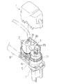
【図1】本発明の全体構成を示す展開斜視図である。
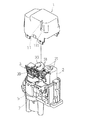
【図2】本発明の主要部を成すケース及びそこに設けられるガイド部の全体構成を示す斜視図である。
【図3】本発明の主要部を成す基盤、電動モータ、ケース、ホルダの相対関係を示す展開斜視図である。
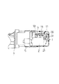
【図4】本発明にかかる基盤、電動モータ、ケースの組立状態を示す断面図である。
【図5】従来のものの全体構成を示す展開斜視図である。
【符号の説明】
1 ケース
11 ガイド部(突起状ガイド部)
111 傾斜面
2 電動モータ
21 入力端子(凹陥状入力端子)
3 基盤
31 出力端子(プラグ状出力端子)
33 制御手段
39 一方の側端部
5 ホルダ
6 ギヤ装置
7 ベース部材
71 シャフト部
8 ミラーハウジング[0001]
TECHNICAL FIELD OF THE INVENTION
The present invention relates to an electric storage device for a mirror, and in particular, to a plug-shaped terminal provided on a base on which control means for controlling the operation of an electric motor is mounted, and an electric motor into which the plug-shaped terminal is inserted. In order to strengthen the connection between the motor-side input terminal and the motor-side input terminal, a guide unit that acts to press the base against the electric motor is provided inside the case. It is about.
[0002]
[Prior art]
In general, an electric storage device for a mirror, particularly an electric storage device for a door mirror, is connected to a
[0003]
[Problems to be solved by the invention]
In such a configuration, between the
[0004]
[Means for Solving the Problems]
In order to solve the above problems, the present invention has taken the following measures. That is, in the invention described in
[0005]
By adopting such a configuration, in the case of the present invention, when the case is mounted so as to cover the electric motor and the base, the base is provided by the action of the guide portion provided inside the case. The plug-shaped output terminal provided on the electric motor is smoothly inserted into the concave input terminal provided on the electric motor side. Therefore, the two terminals are reliably connected. In particular, in the case of the present invention, a guide portion having a surface inclined to one side is provided on the inner surface side of the case, and this guide portion is one end of the base when the case is mounted. Since the plug-shaped terminal is in contact with the side where the plug-shaped terminal is present, the plug-shaped terminal is pushed into the recessed terminal side of the electric motor side at the inclined surface according to the work during the mounting work of the case. Is generated. Therefore, by this component force, the plug-shaped terminal is reliably inserted and fitted into the recessed terminal provided in the electric motor.
[0006]
Next, the second aspect of the invention will be described. This is also basically the same as the first aspect. That is, in the present invention, in the electric storage device for a mirror according to the first aspect, the case is formed of a predetermined plastic material, and the guide portion also functions as a rib in the case. The structure was adopted. By adopting such a configuration, in the case of the present invention, the guide portion serves as a reinforcing rib in the case, so that the case is made lighter and has considerable strength. Will be able to Further, such a case can be formed of a plastic material, so that the mass of the entire case can be reduced and the manufacturing cost can be reduced.
[0007]
Next, a third aspect of the present invention will be described. This is also basically the same as the first or second aspect. That is, in the present invention, in the electric storage device for a mirror according to
[0008]
BEST MODE FOR CARRYING OUT THE INVENTION
An embodiment of the present invention will be described with reference to FIGS. Although related to the present embodiment, as shown in FIG. 1, the configuration is such that an
[0009]
In the
[0010]
On the other hand, in such a configuration, as shown in FIG. 3, a part of the
[0011]
By adopting such a configuration, in the present embodiment, when the
[0012]
【The invention's effect】
According to the present invention, an electric motor, a gear device such as a worm mechanism serving to transmit power from the electric motor, a base member fixed to the door side, and a shaft portion of the base member The electric motor and the gear device, which are mounted so as to be capable of relative rotational movement, are connected to a mirror housing for accommodating a mirror, and rotationally move the mirror housing around the shaft portion. An electric storage device for a mirror, comprising: a holder; a base in the holder, on which control means for controlling the operation of the electric motor is mounted; and a case provided to cover the base and the electric motor. A part of the electric motor is provided with a concave input terminal that contributes to power supply to the electric motor, A plug-shaped output terminal is provided on a part of the board, and the output terminal on the base is fitted to the input terminal on the electric motor side. A guide portion having an inclined surface and having a projecting shape is provided. On the other hand, when the case is mounted so as to cover the electric motor and the base, the guide portion is provided inside the case. The provided guide portion comes into contact with one end of the base to act to push a plug-shaped output terminal provided on the base into a concave input terminal provided on the electric motor. When mounting the case so as to cover the electric motor and the base, the action of the guide portion provided on the inside of the case causes the plug shape provided on the base to be adopted. The output terminal of Come to be pushed into the electric motor concave shape provided in side input the terminal, now the both terminals to each other is reliably bonded.
[0013]
Specifically, in the case of the present invention, when the case is mounted, even if the two terminals are not correctly coupled, the inclined surface forming the guide portion is located at one position of the base. The side end portion comes into contact with the side where the plug-shaped terminal is present, and the plug-shaped terminal is pushed into the recessed terminal side of the electric motor side at the inclined surface according to the mounting work of the case. Since an acting component force is generated, the plug-like terminal is securely inserted into the recessed terminal provided in the electric motor and fitted therein by this component force. As a result, the two terminals are reliably connected.
[0014]
Further, in the present invention, the case is formed of a predetermined plastic material, and the guide is configured to also serve as a rib in the case. The case serves as a reinforcing rib in the case, so that the case can be made lighter and have predetermined strength and rigidity. In addition, since such a case is formed of a plastic material, it is possible to reduce the mass of the entire case and the manufacturing cost.
[Brief description of the drawings]
FIG. 1 is a developed perspective view showing the overall configuration of the present invention.
FIG. 2 is a perspective view showing an entire configuration of a case constituting a main part of the present invention and a guide part provided therein.
FIG. 3 is an exploded perspective view showing a relative relationship among a base, an electric motor, a case, and a holder, which are main parts of the present invention.
FIG. 4 is a sectional view showing an assembled state of a base, an electric motor, and a case according to the present invention.
FIG. 5 is an exploded perspective view showing the entire structure of a conventional device.
[Explanation of symbols]
1
111
3
33 control means 39 one
Claims (3)
Priority Applications (1)
| Application Number | Priority Date | Filing Date | Title |
|---|---|---|---|
| JP2002324925A JP4183482B2 (en) | 2002-11-08 | 2002-11-08 | Electric storage device for mirror |
Applications Claiming Priority (1)
| Application Number | Priority Date | Filing Date | Title |
|---|---|---|---|
| JP2002324925A JP4183482B2 (en) | 2002-11-08 | 2002-11-08 | Electric storage device for mirror |
Publications (2)
| Publication Number | Publication Date |
|---|---|
| JP2004155367A true JP2004155367A (en) | 2004-06-03 |
| JP4183482B2 JP4183482B2 (en) | 2008-11-19 |
Family
ID=32804320
Family Applications (1)
| Application Number | Title | Priority Date | Filing Date |
|---|---|---|---|
| JP2002324925A Expired - Fee Related JP4183482B2 (en) | 2002-11-08 | 2002-11-08 | Electric storage device for mirror |
Country Status (1)
| Country | Link |
|---|---|
| JP (1) | JP4183482B2 (en) |
Cited By (3)
| Publication number | Priority date | Publication date | Assignee | Title |
|---|---|---|---|---|
| EP1908634A3 (en) * | 2006-10-03 | 2008-11-05 | Ichikoh Industries, Ltd. | Motor assembly |
| KR100982360B1 (en) * | 2008-05-20 | 2010-09-14 | (주) 보쉬전장 | Automobile Door Actuator Motor Support Case Structure |
| JP2022189551A (en) * | 2021-06-11 | 2022-12-22 | 株式会社ペンストン | Vehicular viewing device including electric storage unit |
-
2002
- 2002-11-08 JP JP2002324925A patent/JP4183482B2/en not_active Expired - Fee Related
Cited By (4)
| Publication number | Priority date | Publication date | Assignee | Title |
|---|---|---|---|---|
| EP1908634A3 (en) * | 2006-10-03 | 2008-11-05 | Ichikoh Industries, Ltd. | Motor assembly |
| US7652403B2 (en) | 2006-10-03 | 2010-01-26 | Ichikoh Industries, Ltd. | Motor assembly usable for an outer motor of a vehicle |
| KR100982360B1 (en) * | 2008-05-20 | 2010-09-14 | (주) 보쉬전장 | Automobile Door Actuator Motor Support Case Structure |
| JP2022189551A (en) * | 2021-06-11 | 2022-12-22 | 株式会社ペンストン | Vehicular viewing device including electric storage unit |
Also Published As
| Publication number | Publication date |
|---|---|
| JP4183482B2 (en) | 2008-11-19 |
Similar Documents
| Publication | Publication Date | Title |
|---|---|---|
| US7770423B2 (en) | Electro-mechanical lock structure | |
| KR200362183Y1 (en) | Electric motorized hinge apparatus | |
| JP2008312435A (en) | Motor | |
| CN101314341A (en) | Exterior mirror device for vehicle | |
| JP4505818B2 (en) | Portable nailer | |
| JP4183482B2 (en) | Electric storage device for mirror | |
| JP3997650B2 (en) | Electric rotary tool | |
| JP5673035B2 (en) | Portable cutting machine or power tool | |
| JP3886692B2 (en) | Pop-up key | |
| KR100758340B1 (en) | Terminal box for indoor electricity supply in apartment houses | |
| JP4099032B2 (en) | motor | |
| JP3339373B2 (en) | Connector structure of electronic unit in electric retractable door mirror | |
| JP2014133501A (en) | Electric storage unit of outside mirror device for vehicle and outside mirror device for vehicle | |
| KR100223690B1 (en) | Motor drive apparatus | |
| JP2820325B2 (en) | Electric stapler | |
| JP2007207015A (en) | Multi-directional input device | |
| JP3110205U (en) | Vibrator motor housing and electrical connector | |
| JP4299627B2 (en) | Fragrance generator and driving method thereof | |
| JP3086991B2 (en) | Power tool switch mechanism | |
| JP3974330B2 (en) | Vehicle door lock device | |
| JP6684636B2 (en) | Substrate assembly structure and substrate assembly method | |
| CN100525691C (en) | Electrical household food processor with simplified control | |
| JPH11230154A (en) | Hinge device, flip and cellular phone | |
| JP4397285B2 (en) | Variable resistor | |
| JP5473150B2 (en) | switch |
Legal Events
| Date | Code | Title | Description |
|---|---|---|---|
| A621 | Written request for application examination |
Free format text: JAPANESE INTERMEDIATE CODE: A621 Effective date: 20050926 |
|
| TRDD | Decision of grant or rejection written | ||
| A01 | Written decision to grant a patent or to grant a registration (utility model) |
Free format text: JAPANESE INTERMEDIATE CODE: A01 Effective date: 20080826 |
|
| A01 | Written decision to grant a patent or to grant a registration (utility model) |
Free format text: JAPANESE INTERMEDIATE CODE: A01 |
|
| A61 | First payment of annual fees (during grant procedure) |
Free format text: JAPANESE INTERMEDIATE CODE: A61 Effective date: 20080902 |
|
| FPAY | Renewal fee payment (event date is renewal date of database) |
Free format text: PAYMENT UNTIL: 20110912 Year of fee payment: 3 |
|
| R150 | Certificate of patent or registration of utility model |
Ref document number: 4183482 Country of ref document: JP Free format text: JAPANESE INTERMEDIATE CODE: R150 Free format text: JAPANESE INTERMEDIATE CODE: R150 |
|
| FPAY | Renewal fee payment (event date is renewal date of database) |
Free format text: PAYMENT UNTIL: 20110912 Year of fee payment: 3 |
|
| FPAY | Renewal fee payment (event date is renewal date of database) |
Free format text: PAYMENT UNTIL: 20140912 Year of fee payment: 6 |
|
| R250 | Receipt of annual fees |
Free format text: JAPANESE INTERMEDIATE CODE: R250 |
|
| R250 | Receipt of annual fees |
Free format text: JAPANESE INTERMEDIATE CODE: R250 |
|
| R250 | Receipt of annual fees |
Free format text: JAPANESE INTERMEDIATE CODE: R250 |
|
| R250 | Receipt of annual fees |
Free format text: JAPANESE INTERMEDIATE CODE: R250 |
|
| R250 | Receipt of annual fees |
Free format text: JAPANESE INTERMEDIATE CODE: R250 |
|
| R250 | Receipt of annual fees |
Free format text: JAPANESE INTERMEDIATE CODE: R250 |
|
| R250 | Receipt of annual fees |
Free format text: JAPANESE INTERMEDIATE CODE: R250 |
|
| LAPS | Cancellation because of no payment of annual fees |