JP2004156830A - Freezer and refrigerator - Google Patents
Freezer and refrigerator Download PDFInfo
- Publication number
- JP2004156830A JP2004156830A JP2002322399A JP2002322399A JP2004156830A JP 2004156830 A JP2004156830 A JP 2004156830A JP 2002322399 A JP2002322399 A JP 2002322399A JP 2002322399 A JP2002322399 A JP 2002322399A JP 2004156830 A JP2004156830 A JP 2004156830A
- Authority
- JP
- Japan
- Prior art keywords
- refrigerator
- refrigerant
- leakage
- unit
- refrigeration cycle
- Prior art date
- Legal status (The legal status is an assumption and is not a legal conclusion. Google has not performed a legal analysis and makes no representation as to the accuracy of the status listed.)
- Withdrawn
Links
Images

Classifications
-
- F—MECHANICAL ENGINEERING; LIGHTING; HEATING; WEAPONS; BLASTING
- F25—REFRIGERATION OR COOLING; COMBINED HEATING AND REFRIGERATION SYSTEMS; HEAT PUMP SYSTEMS; MANUFACTURE OR STORAGE OF ICE; LIQUEFACTION SOLIDIFICATION OF GASES
- F25B—REFRIGERATION MACHINES, PLANTS OR SYSTEMS; COMBINED HEATING AND REFRIGERATION SYSTEMS; HEAT PUMP SYSTEMS
- F25B2400/00—Component parts or details not otherwise provided for in this subclass
- F25B2400/12—Inflammable refrigerants
Landscapes
- Cold Air Circulating Systems And Constructional Details In Refrigerators (AREA)
- Devices That Are Associated With Refrigeration Equipment (AREA)
Abstract
【課題】本体設置の後に運転開始動作を行なう場合において引火などの不慮の事故を確実に抑制することが可能な冷凍・冷蔵庫を提供する。
【解決手段】冷凍・冷蔵庫本体100は、被冷却物を収納する庫内を冷却するための冷凍サイクル部30と、その内部に封入されて循環し、圧縮と膨張を繰り返し気化熱を吸収して冷却を行なうためのハイドロカーボン系冷媒と、冷媒の漏洩を検知するための冷媒漏洩検知装置24および26と、本体の動作を制御するための制御部36とを備える。制御部36は、本体に電力の供給が開始される際に、冷凍サイクル部30の作動に優先して所定の時間冷媒漏洩検知装置24および26により冷媒の漏洩を検知させて漏洩の評価を行なう。冷媒の漏洩が認められる場合は、電力の供給を遮断する。
【選択図】 図1An object of the present invention is to provide a freezer / refrigerator capable of reliably suppressing an accident such as a fire when starting operation after installation of a main body.
A refrigeration / refrigerator body (100) is provided with a refrigeration cycle unit (30) for cooling the inside of a refrigerator for storing an object to be cooled, and is enclosed and circulated therein to repeatedly compress and expand to absorb vaporization heat. It includes a hydrocarbon-based refrigerant for cooling, refrigerant leakage detection devices 24 and 26 for detecting leakage of the refrigerant, and a control unit 36 for controlling the operation of the main body. When the supply of electric power to the main body is started, the control unit 36 allows the refrigerant leakage detection devices 24 and 26 to detect refrigerant leakage for a predetermined time prior to the operation of the refrigeration cycle unit 30 and evaluates leakage. . If leakage of refrigerant is observed, cut off the power supply.
[Selection diagram] Fig. 1
Description
【0001】
【発明の属する技術分野】
本発明は、可燃性冷媒を用いた冷凍・冷蔵庫に関するものである。
【0002】
【従来の技術】
近年、オゾン層破壊及び地球温暖化等環境問題の面から冷凍・冷蔵庫における冷媒の見直しが強く求められている。機器の冷媒としては従来から使用されているクロロフルオロカーボン系冷媒からハイドロクロロフルオロカーボン系冷媒に代替されている。
【0003】
ところが、地球温暖化の問題に対しては、ハイドロクロロフルオロカーボン系冷媒の採用は充分な対策とはならないため、環境への影響が極めて少ないハイドロカーボン系冷媒に注目が集まり一部商品化がされ始めている。
【0004】
しかしながら、ハイドロカーボン系冷媒においては可燃性を有するがため、安全面での充分な配慮が必要である。さらに、冷凍・冷蔵庫におけるサイクル用の冷媒として用いる場合は、何らかの事故・不良などにより万が一冷媒漏れが生じたとしても引火など災害を誘発しないようにする必要がある。
【0005】
そのため、冷凍・冷蔵庫を構成する部材、システムなどにおいて種々の対策が施されているのが現状である。
【0006】
ここで第1の従来例は、可燃性冷媒を用いた冷蔵庫において以下のような方法が公知である(たとえば、特許文献1を参照)。すなわち、複数の貯蔵室の最下部に位置する貯蔵室内に運転開始スイッチを設置したため、運転開始前に必ず扉を開放しなければならないため、自重で最下部の貯蔵室内に滞留した冷媒を外部に拡散するという作用を有し、さらに運転スイッチに電気接点を設けないため、冷蔵庫の初回通電時に、保管あるいは輸送中の貯蔵室内への可燃性冷媒の漏洩により、何らかの電気的な火花等で着火し、引火する危険を防止する方法が開示されている。
【0007】
一方、第2の従来例では、可燃性冷媒を用いた冷凍装置において以下のような方法が公知である(たとえば、特許文献2を参照)。すなわち、冷凍装置の電源スイッチを洩れ冷媒ガスが自重で溜まりやすい下部室内に設けられ、冷凍装置設置後に電源スイッチを入れる際に、下部室の扉を開くことで、高濃度の洩れ冷媒ガスが戸外に排気され、庫内のガス濃度が低減するので、制御リレーの接点を密封することをせずに不慮の事故を未然に防止する方法が開示されている。
【0008】
【特許文献1】
特開2000−121209号公報明細書
【0009】
【特許文献2】
特開2000−146429号公報明細書
【0010】
【発明が解決しようとする課題】
ところが、冷凍・冷蔵庫を新しく購入したとき或いは引越しなどにより移動したとき、本体設置後の運転開始動作は、本体に電力が供給されること(例えば電源コードをコンセントに差し込むこと)である。この場合、生産された工場からの輸送中或いはユーザーの引越しによる輸送中における衝撃などにより冷凍サイクルに封入されている冷媒ガスが漏れ、庫内に滞留するといった場合が考えられる。
【0011】
そして、充分な点検をすることなく前述の運転操作を行なう事により漏れた冷媒ガスは、本体内部のリレースイッチまたはヒーターなどの熱源に触れ引火等の不慮の事故に到る恐れがある。
【0012】
本発明は、上記のような問題点を解決するためになされたものであって、その目的は、本体設置の後に運転開始動作を行なう場合において引火など不慮の事故を確実に抑制することが可能な冷凍・冷蔵庫を提供することにある。
【0013】
【課題を解決するための手段】
上記目的を達成するために、冷凍・冷蔵庫であって、被冷却物を収納する庫内を冷却するための冷凍サイクル部と、冷凍サイクル部の内部に封入されて循環し、圧縮と膨張を繰り返し気化熱を吸収して冷却を行なうための可燃性冷媒と、可燃性冷媒の漏洩を検知するための冷媒漏洩検知手段と、冷凍・冷蔵庫の動作を制御するための制御手段とを備え、制御手段は冷凍・冷蔵庫に電力の供給が開始される際に、冷凍サイクルの作動に優先して所定の時間、冷媒漏洩検知手段により可燃性冷媒の漏洩を検知させ、漏洩の評価を行なうための漏洩評価手段を含む。
【0014】
好ましくは、制御手段は漏洩評価手段により可燃性冷媒の漏洩が認められる場合は、電力の供給を遮断する。
【0015】
好ましくは、庫内から冷凍サイクル部への空気の流れを生成するための第1の送風機をさらに備え、冷媒漏洩検知手段は、第1の送風機が生成する空気の流れの下流側に設けられる第1の冷媒漏洩検知手段を含み、制御手段は可燃性冷媒の漏洩の評価を行なう際に、第1の送風機を動作させる。
【0016】
好ましくは、冷凍・冷蔵庫は冷凍サイクル部が可燃性冷媒を液化するための凝縮器を含み、凝縮器と外部との間に空気の流れを生成するための第2の送風機をさらに備え、冷媒漏洩検知手段は第2の送風機が生成する空気の流れの下流側に設けられる第2の冷媒漏洩検知手段を含み、制御手段は可燃性冷媒の漏洩の評価を行なう際に、第2の送風機を動作させる。
【0017】
好ましくは、漏洩評価手段により可燃性冷媒の漏洩が認められる際に、漏洩を報知するための報知手段をさらに備える。
【0018】
好ましくは、漏洩評価手段により可燃性冷媒の漏洩が認められる際に、漏洩を表示をするための表示手段をさらに備える。
【0019】
【発明の実施の形態】
以下に、本発明の実施の形態について図面を用いて説明する。
【0020】
図1は、本発明の冷凍・冷蔵庫の断面図である。
図1を参照して、冷凍・冷蔵庫本体100は、本体に取り付けられた扉2と、扉4と、冷凍・冷蔵庫本体内の熱漏洩を最小限にするための断熱材10と、扉2および扉4および断熱材10により庫内を被冷却物の環境条件に合わせて分割・配設された冷蔵室6と、冷凍室8と、庫内を冷却する冷凍サイクル部30と、庫内から冷凍サイクル部30へ空気の流れを生成する吸熱用の送風機20と、冷凍サイクル部30と外部との間に空気の流れを生成する放熱用の送風機22と冷凍サイクル部30内部に設けられた冷媒漏洩検知装置24および26と、冷凍サイクル部30および送風機20および22の作動の制御をするための制御部36と、冷凍サイクル部30内部に封入されたハイドロカーボン系冷媒32(図示せず)とを備える。
【0021】
冷凍サイクル部30は、圧縮機12と、凝縮器14と、キャピラリチューブ或いは膨張弁などの膨張機構16と、蒸発器18とを含む。
【0022】
圧縮機12は冷凍・冷蔵庫本体100の背面下部に設けられている。凝縮器14は複数の構成部品を含み、その一部は、圧縮機12と同様本体の背面下部に設けられている。凝縮部14の他の構成部品は、本体の前面、側面、背面部などの断熱材10内に設けられている。凝縮器14の一端部は、圧縮機12の吐出部に接続されている。凝縮器14の他端部はドライヤ34(図示せず)を介してキャピラリチューブ或いは膨張弁などの膨張機構16入口部に接続されている。そして、膨張機構16の出口部は、冷蔵庫内の背面に形成されている冷気循環経路内の蒸発器18入口部に接続される。蒸発器18の出口部は圧縮機12の入口部に接続されている。
【0023】
この冷凍サイクル部30の配管内にはブタン、イソブタン、プロパンなどハイドロカーボン系冷媒32が封入されている。
【0024】
冷媒漏洩検知装置24は、送風機20が生成する空気の流れの下流でかつ蒸発器18の近傍に設けられる。一方、冷媒漏洩検知装置26は、送風機22が生成する空気の流れの下流でかつ凝縮器14の近傍に設けられている。
【0025】
制御部36は、タイマーを含んでおり、本体に電力が供給されるとき、例えば、電源コードがコンセントに差し込まれると同時にカウントを始める。タイマーにより所定の時間送風機20および22を作動させ、その間に冷媒漏洩検知装置24および26により冷媒漏洩の検知をさせて漏洩の評価を行なう。漏洩が検知される場合、制御部36は、冷凍サイクル部30の作動を行なわずに電力供給を遮断する。さらに、音声、ブザー等の報知装置或いは警告ランプ、液晶表示等の表示装置を作動させることにより、周囲に異常を通報する。
【0026】
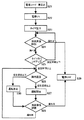
図2は、図1に示す冷凍・冷蔵庫本体100の据え付けから運転までのフローチャートである。
【0027】
図2を参照して、ユーザーは、冷凍・冷蔵庫本体100の設置後、運転を開始するために電源コードをコンセントに差し込む(ステップS21)。
【0028】
冷凍・冷蔵庫本体100は、電源コードを介して電力の供給を受け、電源ONとなる(ステップS22)。
【0029】
制御部36は、運転開始時にタイマーを動作させる(ステップS23)。
制御部36は、タイマーを動作させた後、冷媒漏洩検知装置により冷媒ガスの漏洩のチェック評価を行なう(ステップS24)。
【0030】
この時、制御部36は、送風機20および22を作動させることにより、配管からの僅かな冷媒ガスの漏れをも確実に検知することが可能となる。
【0031】
ステップS24において冷媒ガスの漏洩が検知された場合、直ちに電源の供給を遮断して電源OFFとする(ステップS29)。
【0032】
ステップS24において冷媒ガスの漏洩が検知されない場合、タイマーの設定時間(約3分〜5分)が経過したかの判断をする(ステップS25)。
【0033】
ステップS25においてタイマーによりカウントされた経過時間が設定時間以下である場合は、ステップS24に戻り、再び漏洩評価を行なう。
【0034】
一方、ステップS25においてタイマーによりカウントされた経過時間が設定時間以上となる場合、制御部36は、庫内温度が設定温度以上であるかどうかを庫内に設けられている温度計等を用いて確認を行なう(ステップS26)。
【0035】
ステップS26において庫内温度が設定温度以上の場合は、制御部36は運転を開始する(ステップS27)。
【0036】
一方、ステップS26において庫内温度が設定温度以下の場合は、運転を休止する(ステップS30)。
【0037】
制御部36は、運転の動作中、休止中に関わらず常時冷媒漏洩検知装置24および26により冷媒ガスの漏れチェック評価を行なう(ステップS28)。
【0038】
ステップS28において冷媒ガスの漏れが検知される場合は、制御部36は冷凍サイクル部30の作動を行なわずに直ちに電力供給を遮断する(ステップS29)。
【0039】
一方、ステップS28において冷媒ガスの漏れが検知されない場合は、処理をステップS26に移行する。
【0040】
制御部36は、ステップS29において電源OFFとなった場合、異常が発生したことを冷凍・冷蔵庫本体100の外表面上にて警告ランプ、液晶表示など表示装置或いは音声、ブザーなどの報知装置により周囲に知らしめる。そのため、冷凍・冷蔵庫を購入或いは引越しした時の据え付け後、本体内部に冷媒ガスが漏洩した状態において運転開始をする場合においては、運転を停止して周囲に異常を通報することにより引火等の事故を未然に防ぐことが可能である。
【0041】
今回開示された実施の形態はすべての点で例示であって制限的なものではないと考えられるべきである。本発明の範囲は上記した説明ではなくて特許請求の範囲によって示され、特許請求の範囲と均等の意味および範囲内でのすべての変更が含まれていることが意図される。
【0042】
【発明の効果】
以上説明したように、本発明の可燃性冷媒を用いた冷凍・冷蔵庫によれば、本体の設置を行なったのちに電力を供給したとき、所定の時間冷媒漏洩検知装置により漏洩評価を行なうことができる。さらに、冷媒の漏洩が検知される場合は、電力供給を遮断し、表示装置或いは報知装置により周囲に異常を通報することができる。
【図面の簡単な説明】
【図1】本発明の実施の形態における冷凍・冷蔵庫の断面図である。
【図2】冷凍・冷蔵庫本体100の据え付けから運転までのフローチャートである。
【符号の説明】
100 冷凍・冷蔵庫本体、2、4 扉、6 冷蔵室、8 冷凍室、10 断熱材、12 圧縮機、14 凝縮器、16 膨張機構、18 蒸発器、20、22 送風機、24 冷媒漏洩検知装置、26 冷媒漏洩検知装置、30 冷凍サイクル部、32 ハイドロカーボン系冷媒、34 ドライヤ、36 制御部。[0001]
TECHNICAL FIELD OF THE INVENTION
The present invention relates to a refrigerator / refrigerator using a combustible refrigerant.
[0002]
[Prior art]
In recent years, reexamination of refrigerants in refrigerators and refrigerators has been strongly demanded in view of environmental problems such as ozone depletion and global warming. As a refrigerant for equipment, a chlorofluorocarbon-based refrigerant conventionally used is replaced with a hydrochlorofluorocarbon-based refrigerant.
[0003]
However, the adoption of hydrochlorofluorocarbon-based refrigerants is not a sufficient measure against the problem of global warming, and attention has been focused on hydrocarbon-based refrigerants that have very little impact on the environment, and some commercialization has begun. I have.
[0004]
However, since the hydrocarbon-based refrigerant has flammability, it is necessary to give due consideration to safety. Further, when the refrigerant is used as a refrigerant for a cycle in a refrigerator / refrigerator, it is necessary to prevent a disaster such as ignition from occurring even if the refrigerant leaks due to some accident or failure.
[0005]
Therefore, at present, various countermeasures are taken in members, systems, and the like that constitute the refrigerator / refrigerator.
[0006]
Here, as a first conventional example, the following method is known in a refrigerator using a combustible refrigerant (for example, see Patent Document 1). That is, since the operation start switch is installed in the storage room located at the bottom of the plurality of storage rooms, the door must be opened before the operation starts, so that the refrigerant stagnated in the bottom storage room by its own weight is externalized. It has the effect of spreading, and since no electrical contact is provided on the operation switch, the ignition of the refrigerator by some kind of electric spark etc. due to the leakage of the flammable refrigerant into the storage room during storage or transportation when the refrigerator is first energized. A method for preventing the danger of ignition is disclosed.
[0007]
On the other hand, in the second conventional example, the following method is known in a refrigerating apparatus using a combustible refrigerant (for example, see Patent Document 2). That is, the power switch of the refrigerating apparatus is provided in the lower chamber where the refrigerant gas easily leaks and accumulates under its own weight, and when the power switch is turned on after the installation of the refrigerating apparatus, the door of the lower chamber is opened so that the high-concentration leaked refrigerant gas is discharged outdoors A method is disclosed in which an accident is prevented beforehand because the exhaust gas is exhausted and the gas concentration in the storage is reduced, so that the contacts of the control relay are not sealed.
[0008]
[Patent Document 1]
Japanese Patent Application Laid-Open No. 2000-121209
[Patent Document 2]
Japanese Patent Application Laid-Open No. 2000-146429
[Problems to be solved by the invention]
However, when the refrigerator / refrigerator is newly purchased or moved due to moving or the like, the operation start operation after the installation of the main body is that power is supplied to the main body (for example, a power cord is plugged into an outlet). In this case, it is conceivable that the refrigerant gas sealed in the refrigeration cycle leaks due to an impact during transportation from the factory where it was produced or during transportation due to a user's moving, and stays in the refrigerator.
[0011]
Then, the refrigerant gas leaked by performing the above-mentioned operation without sufficient inspection may contact a heat source such as a relay switch or a heater inside the main body and cause an accident such as ignition.
[0012]
The present invention has been made to solve the above-described problems, and an object of the present invention is to surely suppress an accident such as a fire when starting operation after installing the main body. A refrigerator / freezer.
[0013]
[Means for Solving the Problems]
In order to achieve the above object, a refrigeration / refrigerator, which is a refrigeration cycle unit for cooling the inside of a refrigerator for storing an object to be cooled, and sealed and circulated inside the refrigeration cycle unit, repeatedly compressing and expanding. Control means comprising: a combustible refrigerant for absorbing heat of vaporization for cooling, a refrigerant leak detection unit for detecting leakage of the combustible refrigerant, and a control unit for controlling operation of the refrigerator / refrigerator. Means that when the supply of electric power to the refrigerator / refrigerator is started, the leakage of the combustible refrigerant is detected by the refrigerant leakage detection means for a predetermined time prior to the operation of the refrigeration cycle, and the leakage is evaluated to evaluate the leakage. Including means.
[0014]
Preferably, the control means cuts off the supply of the electric power when the leakage evaluation means detects the leakage of the flammable refrigerant.
[0015]
Preferably, the air conditioner further includes a first blower for generating a flow of air from the inside of the refrigerator to the refrigeration cycle section, and the refrigerant leak detection unit is provided on a downstream side of the flow of air generated by the first blower. The control means operates the first blower when evaluating the leakage of the flammable refrigerant.
[0016]
Preferably, the refrigeration / refrigerator has a refrigeration cycle unit including a condenser for liquefying the combustible refrigerant, further comprising a second blower for generating a flow of air between the condenser and the outside, The detection means includes a second refrigerant leak detection means provided downstream of the flow of air generated by the second blower, and the control means operates the second blower when evaluating the leakage of the flammable refrigerant. Let it.
[0017]
Preferably, the system further includes a notifying unit for notifying the leakage when the leakage of the combustible refrigerant is recognized by the leakage evaluation unit.
[0018]
Preferably, the apparatus further includes a display unit for displaying the leakage when the leakage of the combustible refrigerant is recognized by the leakage evaluation unit.
[0019]
BEST MODE FOR CARRYING OUT THE INVENTION
Hereinafter, embodiments of the present invention will be described with reference to the drawings.
[0020]
FIG. 1 is a sectional view of a refrigerator / refrigerator of the present invention.
Referring to FIG. 1, a refrigerator /
[0021]
The
[0022]
The
[0023]
A hydrocarbon-based refrigerant 32 such as butane, isobutane, and propane is sealed in the piping of the
[0024]
The refrigerant
[0025]
The
[0026]
FIG. 2 is a flowchart from installation to operation of the freezing / refrigerator
[0027]
Referring to FIG. 2, after installing freezing / refrigerator
[0028]
The freezing / refrigerator
[0029]
The
After operating the timer, the
[0030]
At this time, by operating the
[0031]
When the leakage of the refrigerant gas is detected in step S24, the power supply is immediately cut off and the power is turned off (step S29).
[0032]
If the leakage of the refrigerant gas is not detected in step S24, it is determined whether the set time of the timer (about 3 to 5 minutes) has elapsed (step S25).
[0033]
If the elapsed time counted by the timer is equal to or shorter than the set time in step S25, the process returns to step S24, and the leak evaluation is performed again.
[0034]
On the other hand, if the elapsed time counted by the timer in step S25 is equal to or longer than the set time, the
[0035]
If the internal temperature is equal to or higher than the set temperature in step S26, the
[0036]
On the other hand, if the internal temperature is equal to or lower than the set temperature in step S26, the operation is stopped (step S30).
[0037]
The
[0038]
When the leakage of the refrigerant gas is detected in step S28, the
[0039]
On the other hand, if no leakage of the refrigerant gas is detected in step S28, the process proceeds to step S26.
[0040]
When the power is turned off in step S29, the
[0041]
The embodiments disclosed this time are to be considered in all respects as illustrative and not restrictive. The scope of the present invention is defined by the terms of the claims, rather than the description above, and is intended to include any modifications within the scope and meaning equivalent to the terms of the claims.
[0042]
【The invention's effect】
As described above, according to the refrigeration / refrigerator using the flammable refrigerant of the present invention, when power is supplied after the main body is installed, it is possible to perform a leakage evaluation by the refrigerant leakage detection device for a predetermined time. it can. Further, when leakage of the refrigerant is detected, the power supply is shut off, and an abnormality can be reported to the surroundings by a display device or a notification device.
[Brief description of the drawings]
FIG. 1 is a sectional view of a refrigerator / refrigerator according to an embodiment of the present invention.
FIG. 2 is a flowchart from installation to operation of the freezing / refrigerator
[Explanation of symbols]
100 freezer / refrigerator body, 2 and 4 doors, 6 refrigerator compartment, 8 freezer compartment, 10 heat insulator, 12 compressor, 14 condenser, 16 expansion mechanism, 18 evaporator, 20, 22 blower, 24 refrigerant leak detector, 26 refrigerant leak detection device, 30 refrigeration cycle unit, 32 hydrocarbon-based refrigerant, 34 dryer, 36 control unit.
Claims (6)
被冷却物を収納する庫内を冷却するための冷凍サイクル部と、
前記冷凍サイクル部の内部に封入されて循環し、圧縮と膨張を繰り返し気化熱を吸収して冷却を行なうための可燃性冷媒と、
前記可燃性冷媒の漏洩を検知するための冷媒漏洩検知手段と、
前記冷凍・冷蔵庫の動作を制御するための制御手段とを備え、
前記制御手段は、前記冷凍・冷蔵庫に電力の供給が開始される際に、前記冷凍サイクルの作動に優先して所定の時間、前記冷媒漏洩検知手段により前記可燃性冷媒の漏洩を検知させ、漏洩の評価を行なうための漏洩評価手段を含む、冷凍・冷蔵庫。Freezer and refrigerator,
A refrigeration cycle unit for cooling the inside of the refrigerator storing the object to be cooled;
A flammable refrigerant that is sealed and circulated inside the refrigeration cycle unit, repeatedly compresses and expands, absorbs heat of vaporization, and performs cooling,
Refrigerant leak detection means for detecting the leakage of the flammable refrigerant,
Comprising control means for controlling the operation of the refrigerator / refrigerator,
When the supply of electric power to the refrigerator / refrigerator is started, the control unit causes the refrigerant leakage detection unit to detect the leakage of the flammable refrigerant for a predetermined time prior to the operation of the refrigeration cycle. Refrigerator / refrigerator, including leak assessment means for assessing refrigeration.
前記冷媒漏洩検知手段は、前記第1の送風機が生成する空気の流れの下流側に設けられる第1の冷媒漏洩検知手段を含み、
前記制御手段は、前記可燃性冷媒の漏洩の評価を行なう際に、前記第1の送風機を動作させる、請求項2記載の冷凍・冷蔵庫。A first blower for generating a flow of air from the inside of the refrigerator to the refrigeration cycle unit,
The refrigerant leak detection unit includes a first refrigerant leak detection unit provided downstream of the flow of air generated by the first blower,
The refrigerator / refrigerator according to claim 2, wherein the control means operates the first blower when evaluating the leakage of the combustible refrigerant.
前記冷媒漏洩検知手段は、前記第2の送風機が生成する空気の流れの下流側に設けられる第2の冷媒漏洩検知手段を含み、
前記制御手段は、前記可燃性冷媒の漏洩の評価を行なう際に、前記第2の送風機を動作させる、請求項2記載の冷凍・冷蔵庫。The refrigeration / refrigerator, wherein the refrigeration cycle unit includes a condenser for liquefying the combustible refrigerant, and further includes a second blower for generating a flow of air between the condenser and the outside,
The refrigerant leak detection unit includes a second refrigerant leak detection unit provided downstream of the flow of air generated by the second blower,
3. The refrigerator / refrigerator according to claim 2, wherein the control unit operates the second blower when evaluating the leakage of the combustible refrigerant.
Priority Applications (1)
| Application Number | Priority Date | Filing Date | Title |
|---|---|---|---|
| JP2002322399A JP2004156830A (en) | 2002-11-06 | 2002-11-06 | Freezer and refrigerator |
Applications Claiming Priority (1)
| Application Number | Priority Date | Filing Date | Title |
|---|---|---|---|
| JP2002322399A JP2004156830A (en) | 2002-11-06 | 2002-11-06 | Freezer and refrigerator |
Publications (1)
| Publication Number | Publication Date |
|---|---|
| JP2004156830A true JP2004156830A (en) | 2004-06-03 |
Family
ID=32802595
Family Applications (1)
| Application Number | Title | Priority Date | Filing Date |
|---|---|---|---|
| JP2002322399A Withdrawn JP2004156830A (en) | 2002-11-06 | 2002-11-06 | Freezer and refrigerator |
Country Status (1)
| Country | Link |
|---|---|
| JP (1) | JP2004156830A (en) |
Cited By (3)
| Publication number | Priority date | Publication date | Assignee | Title |
|---|---|---|---|---|
| RU2406947C2 (en) * | 2005-05-10 | 2010-12-20 | Бсх Бош Унд Сименс Хаусгерете Гмбх | Refrigerating device with cooling of circulating air |
| CN102313436A (en) * | 2010-07-06 | 2012-01-11 | 无锡松下冷机有限公司 | Refrigerator and automatic fire alarm method thereof |
| WO2014203320A1 (en) * | 2013-06-18 | 2014-12-24 | 三菱電機株式会社 | Refrigerating device |
-
2002
- 2002-11-06 JP JP2002322399A patent/JP2004156830A/en not_active Withdrawn
Cited By (8)
| Publication number | Priority date | Publication date | Assignee | Title |
|---|---|---|---|---|
| RU2406947C2 (en) * | 2005-05-10 | 2010-12-20 | Бсх Бош Унд Сименс Хаусгерете Гмбх | Refrigerating device with cooling of circulating air |
| CN102313436A (en) * | 2010-07-06 | 2012-01-11 | 无锡松下冷机有限公司 | Refrigerator and automatic fire alarm method thereof |
| WO2014203320A1 (en) * | 2013-06-18 | 2014-12-24 | 三菱電機株式会社 | Refrigerating device |
| GB2528215A (en) * | 2013-06-18 | 2016-01-13 | Mitsubishi Electric Corp | Refrigerating device |
| CN105308395A (en) * | 2013-06-18 | 2016-02-03 | 三菱电机株式会社 | Refrigerating device |
| JPWO2014203320A1 (en) * | 2013-06-18 | 2017-02-23 | 三菱電機株式会社 | Refrigeration equipment |
| CN105308395B (en) * | 2013-06-18 | 2018-01-23 | 三菱电机株式会社 | freezer |
| GB2528215B (en) * | 2013-06-18 | 2018-08-01 | Mitsubishi Electric Corp | Refrigerating apparatus |
Similar Documents
| Publication | Publication Date | Title |
|---|---|---|
| JP3999961B2 (en) | refrigerator | |
| KR20040073565A (en) | Refrigerator having alarm device for alarming leakage of refrigerant | |
| JP3708405B2 (en) | Home appliances using flammable refrigerants | |
| JP4038830B2 (en) | refrigerator | |
| JP2004077000A (en) | refrigerator | |
| RU2409794C1 (en) | Refrigerator | |
| JP2000097527A (en) | Air conditioner and control method thereof | |
| JP4270789B2 (en) | refrigerator | |
| JPH11211293A (en) | Refrigerator | |
| JP2004156830A (en) | Freezer and refrigerator | |
| JP4202630B2 (en) | refrigerator | |
| JP2001093039A (en) | Automatic vending machine | |
| JP2004286315A (en) | Refrigeration circuit safety device | |
| EP4455581A1 (en) | Ice maker with flammable refrigerant leak response system and method of responding to flammable refrigerant leak in ice maker | |
| JP2005207666A (en) | refrigerator | |
| JP2003207259A (en) | refrigerator | |
| JP2001336869A (en) | Freezer refrigerator | |
| JP3733661B2 (en) | refrigerator | |
| JP2004125215A (en) | Refrigerator | |
| JP3907176B2 (en) | refrigerator | |
| JP2000097530A (en) | Cooling storage shed | |
| JP2000121211A (en) | Refrigerator | |
| JP2005331187A (en) | refrigerator | |
| JP2004286392A (en) | refrigerator | |
| JP2003214743A (en) | Refrigerator |
Legal Events
| Date | Code | Title | Description |
|---|---|---|---|
| A300 | Withdrawal of application because of no request for examination |
Free format text: JAPANESE INTERMEDIATE CODE: A300 Effective date: 20060110 |