JP2004158652A - Optical amplifier, transmission wavelength characteristic control method in optical amplifier, and optical transmission system - Google Patents
Optical amplifier, transmission wavelength characteristic control method in optical amplifier, and optical transmission system Download PDFInfo
- Publication number
- JP2004158652A JP2004158652A JP2002323067A JP2002323067A JP2004158652A JP 2004158652 A JP2004158652 A JP 2004158652A JP 2002323067 A JP2002323067 A JP 2002323067A JP 2002323067 A JP2002323067 A JP 2002323067A JP 2004158652 A JP2004158652 A JP 2004158652A
- Authority
- JP
- Japan
- Prior art keywords
- optical
- wavelength
- characteristic
- transmission
- light
- Prior art date
- Legal status (The legal status is an assumption and is not a legal conclusion. Google has not performed a legal analysis and makes no representation as to the accuracy of the status listed.)
- Granted
Links
Images











Classifications
-
- H—ELECTRICITY
- H04—ELECTRIC COMMUNICATION TECHNIQUE
- H04B—TRANSMISSION
- H04B10/00—Transmission systems employing electromagnetic waves other than radio-waves, e.g. infrared, visible or ultraviolet light, or employing corpuscular radiation, e.g. quantum communication
- H04B10/29—Repeaters
- H04B10/291—Repeaters in which processing or amplification is carried out without conversion of the main signal from optical form
- H04B10/293—Signal power control
- H04B10/294—Signal power control in a multiwavelength system, e.g. gain equalisation
- H04B10/2941—Signal power control in a multiwavelength system, e.g. gain equalisation using an equalising unit, e.g. a filter
-
- H—ELECTRICITY
- H04—ELECTRIC COMMUNICATION TECHNIQUE
- H04B—TRANSMISSION
- H04B10/00—Transmission systems employing electromagnetic waves other than radio-waves, e.g. infrared, visible or ultraviolet light, or employing corpuscular radiation, e.g. quantum communication
- H04B10/29—Repeaters
- H04B10/291—Repeaters in which processing or amplification is carried out without conversion of the main signal from optical form
- H04B10/2912—Repeaters in which processing or amplification is carried out without conversion of the main signal from optical form characterised by the medium used for amplification or processing
- H04B10/2916—Repeaters in which processing or amplification is carried out without conversion of the main signal from optical form characterised by the medium used for amplification or processing using Raman or Brillouin amplifiers
Landscapes
- Physics & Mathematics (AREA)
- Electromagnetism (AREA)
- Engineering & Computer Science (AREA)
- Computer Networks & Wireless Communication (AREA)
- Signal Processing (AREA)
- Optical Communication System (AREA)
- Lasers (AREA)
- Diffracting Gratings Or Hologram Optical Elements (AREA)
- Optical Modulation, Optical Deflection, Nonlinear Optics, Optical Demodulation, Optical Logic Elements (AREA)
Abstract
【課題】波長多重光伝送システムにおいて、迅速な光フィルタ制御と効率的な光増幅とを可能とし、ネットワーク拡張時に光波長を変更せず、かつ光波長の増減時の外部擾乱に強く、初期導入コストを抑制しうる、光増幅器を提供する。
【解決手段】光増幅器2が、波長多重光を増幅する増幅媒体14,増幅媒体14の入力光パワーおよび出力光パワーを測定する測定部19,伝送路18に接続され通過波長特性を可変に設定可能な可変利得イコライザ11,上記の伝送路18の種類毎の波長特性を示すデータを保持するデータベース17,取得された伝送路の種類,測定部19にて測定された光パワー,データベース17に保持されたデータとに基づいて可変利得イコライザ11の波長特性に起因する通過逆特性を演算する演算部16,演算部16にて演算された通過逆特性に基づいて可変利得イコライザ11の通過波長特性を設定する設定部16aとをそなえて構成する。
【選択図】 図1In a wavelength division multiplexing optical transmission system, quick optical filter control and efficient optical amplification are enabled, the optical wavelength is not changed when a network is expanded, and it is resistant to external disturbances when the optical wavelength is increased and decreased. Provided is an optical amplifier capable of suppressing costs.
An optical amplifier is connected to an amplifying medium for amplifying wavelength-division multiplexed light, a measuring unit for measuring an input optical power and an output optical power of the amplifying medium, and a transmission line for variably setting a transmission wavelength characteristic. Possible variable gain equalizer 11, database 17 holding data indicating wavelength characteristics for each type of transmission line 18 described above, type of transmission line obtained, optical power measured by measuring unit 19, stored in database 17 A computing unit 16 for computing a pass inverse characteristic caused by the wavelength characteristic of the variable gain equalizer 11 based on the obtained data and a pass wavelength characteristic of the variable gain equalizer 11 based on the pass inverse characteristic computed by the computation unit 16. It comprises a setting section 16a for setting.
[Selection diagram] Fig. 1
Description
【0001】
【発明の属する技術分野】
本発明は、例えば増幅された波長多重光の通過波長特性の制御に用いて好適な、光増幅器,光増幅器における通過波長特性制御方法および光伝送システムに関する。
【0002】
【従来の技術】
近年、インターネットの利用者の急増および映像等の配信サービスの開始に伴い、インターネットのバックボーンとなる基幹系の高速光ネットワークへの常時アクセスが要請されている。単一の光ファイバケーブル(以下、特に断らない限り、ファイバと称する。)に波長の異なる複数の光信号を多重化して伝送する波長分割多重(WDM:Wavelength Division Multiplexing:波長分割多重)方式は、波長数に比例して伝送容量を大きくすることができるため、その実用化が望まれている。
【0003】
多数のファイバが接続された光ネットワークには、高速,大容量および長距離のデータ伝送を行なう波長多重光増幅装置(以下、装置と略称する。)が設けられ、この装置は光増幅器を有する。この光増幅器は、光信号の損失を補償し、これにより、光信号が中継される。損失の原因は、主に、光信号のファイバ外部への散乱又はファイバ内部の不純物による吸収による。
【0004】
光増幅器の一例として、EDFA(erbium−doped optical fiber amplifier:エルビウム添加ファイバ増幅器)がよく知られている。このEDFAは、エルビウム(Er)等の希土類イオンを注入されたファイバ自体からなる光増幅器であって、この増幅機能は、EDFに励起光(ポンプ光)が入力され、その入力励起光がErを励起させ、その励起エネルギがEDFを通過する光信号を増幅させるものである。
【0005】
従来の光増幅器は、波長毎の利得(ゲイン)および損失(ロス)の両偏差の双方を解消するために、次の(J1),(J2)の2種類に分類して光信号を補償していた。
(J1)EDFの利得プロファイル(うねり)の補償
(J2)伝送路損失および誘導ラマン散乱(SRS:Stimulated Raman Scattering)による一次傾斜の補償
この(J1)の利得プロファイルとは利得波長特性(利得の波長依存性)を意味する。この利得プロファイルの形状は、例えば図24(a)に示すような形状であって、この形状は、光ファイバの励起率(δ1/δ0)によって決定される(δ1/δ0は、それぞれ、上準位のイオン密度,全イオン密度を表す。)。ここで、利得波長特性が平坦になるためには、放射のためのホール数を入力光パワーにかかわらず一定にすることが必要である。また、このときの光増幅器の動作状態は、入力光パワーに依存しない自動利得制御(Automatic Gain Control)状態に相当する。ところが、このAGC状態においては、励起が不要(無駄)になることがある。
【0006】
例えば出力光パワーが0[dBm]で足りる場合に、励起率が20[dB]のままであるとき、−10[dBm]の入力光パワーを有する入力光は、増幅後、10[dBm]の値になる。従って、出力波長特性を平坦にするためには、減衰器を用いて、増幅されて得られた10[dBm]分のパワーは、減衰の必要がある。この場合、ネットワーク管理者(管理者,ネットワーク運用者:以下、管理者と称する。)は、自動レベル制御(Automatic Level Control)を実施し、EDFAの出力側に外付けの光フィルタを設けるようにして、利得プロファイルの形状の平坦化を図っている。この外付けの光フィルタを用いる方法が最も消費パワーが少ない。なお、光フィルタについては、後述する。
【0007】
さらに、利得プロファイルは、中継段数が増加すると累積して光信号の品質に影響を与える。このため、伝送路としてEDFが用いられている場合は、光増幅器が、EDFの利得プロファイルに対して逆特性を有する固定フィルタ(帯域が固定されていたフィルタ)を用いて光信号を補償する。
次に、(J2)のSRSとは、高周波数側の光パワーを低周波数側にシフトする伝送ファイバの非線形現象である。このSRSとは、大パワーの単色光を光ファイバに照射したときに、その光ファイバの光学フォノンと相互作用することにより固有な量だけ波長がずれたコヒーレントなストークス光が誘導放出により発生する現象を応用して、ストークス光が信号光と同じ波長となるように単色光の波長を設定し、誘導放出により信号光を増幅させることをいう。そして、このSRSによって、利得プロファイルのうちの一次傾斜が補償されるようになっている。なお、SRSは、誘電体を有するファイバにおいて発生するので、管理者は、伝送路の種類に応じて励起光の出力等を調整している。
【0008】
また、ラマン増幅とは、誘導ラマン散乱効果を利用した増幅であって、励起光パワーと発振波長とを調整することにより所望の利得波長特性を得られる。
従来は、光伝送システムは、EDFと光フィルタとを多段に接続し、EDFについてその入力光の励起光の励起を制御し、かつ帯域特性が固定の固定フィルタを用いて、EDFおよび帯域外の雑音光を抑圧していた。
【0009】
これによって、光伝送システムは、使用中の部品をそのまま利用でき、また、信頼性と低価格とを実現していた。さらに、光伝送システムは、ラマン増幅器をあわせて用いることによって、低雑音なチルト(中継増幅器の利得の一次傾斜を表すパラメータ)を補償していた。各対向局は、中継増幅後の出力レベルが波長について均一でなくなるので、その利得の一次傾斜を監視していた。なお、特に断らない限り、対向局は、中継局(リピータ,リピータ局又はリピータノード)と、光波長多重端局(端局)との双方を含むものとして使用する。
【0010】
さらに、光フィルタを用いた方法が提案されている。光フィルタは、波長毎の利得又は損失量を可変的に調整可能(チューナブル)な可変利得イコライザ(VGEQ:Variable Gain EQualizer)である。この光フィルタは、光増幅器として、消費パワーが小さく、また、利得,損失を調整可能な受動部品を用いており、この機能は、例えば可変フィルタ(商品名:Active Gain Equalilzer)等によって実現される。また、この光フィルタを用いる方法は、光増幅器が光スペクトラムアナライザ(OSA:Optical Spectrum Analyzer)等を用いて、所望の光波長の出力光パワーをモニタすることによって、その可変フィルタの特性を制御するものである(例えば、特許文献1参照)。
【0011】
特許文献1記載の光多重方法は、光多重盤内で波長多重された信号光を、チューナブルフィルタを透過させフォトダイオードで波長毎にそのレベルを測定し、そのレベル値に基づいて設定部が可動光減衰器を調整して各レベルを一定の値に合わせるものである。これによって、波長多重される信号光のレベルを常時、自動的に調整できる。
【0012】
図24(b)は光スペクトラムアナライザを用いた光パワーモニタの一例を示す図である。この図24(b)に示す光増幅器200のゲインブロック200aにて、入力された光信号は増幅され、その増幅光は分波器200bにて波長毎に分波され、各分波光は、通過帯域の異なる複数の光フィルタ200cにて補償される。そして、補償された各光信号は、合波器200dにて合波されて、再度、ゲインブロック200aにて増幅され、その増幅された多重光が次段の光増幅器(図示省略)に出力される。また、ゲインブロック200aから出力された多重光は、光スペクトラムアナライザ(OSA)200eにてモニタされ、予め設定された補償量になるように複数の光フィルタ200cの損失量を調整するようになっている。
【0013】
この光フィルタ200cを用いた方法は、消費パワーおよび機器コストの点で冗長な部品・冗長なパワーに起因するコストを低減するようになっており、これによって、従来の光増幅器が有する波長毎の利得の偏差が解消される。
光伝送システムは、従来、EDFAとラマン増幅器との組合せによって、中継増幅および増幅出力の波長平坦性を実現しており、また、この光信号の補償は、光フィルタ単独で実施されたり、又は光フィルタとSRSとを組み合わせたものにより実施されていた。
【0014】
【特許文献1】
特開平10−276173号公報
【0015】
【発明が解決しようとする課題】
ところで、光フィルタおよびSRSを組み併せた場合において、後段の増幅器としてSRSを用いる場合、前段のEDFAの特性は、後段のSRSに好ましくない影響を与える。具体的には、EDFAの利得プロファイル形状が二次(高次)の動作点に応じて変化すると、管理者は、後段のSRSにより得た利得を波長に応じてアクティブ又はチューナブルに設定できない。この理由は、SRSの利得プロファイルは、伝送路の種類によって決定されるからである。従って、光増幅器は、後段の増幅器としてSRSを用いると、損失した帯域のみを補償できない。
【0016】
このため、二次の動作点が変化しないように、管理者は、前段に設けられたEDFAの励起光出力を調整し、また、必要に応じてラマン増幅を併用した中継増幅を行なっている。具体的には、各中継増幅器が、光波長モニタを用いてフィルタ特性を最適な状態に制御する。
しかしながら、光波長モニタを使用する場合、光伝送システムは、光増幅器の全ての増幅帯域において、特定波長のモニタ光を伝送させる必要がある。そのうえ、このモニタ光は、その光増幅器の利得波長特性をモニタするためだけに用いられるので不要である。さらに、管理者は、モニタ用の光スペクトラムアナライザ等の冗長な機器を顧客に購入させなければならない。従って、顧客に課される初期導入コストが高くなる。
【0017】
また、光スペクトラムアナライザ等を用いるフィルタ制御方法は、光増幅器がモニタ結果を伝送路の上流側に対してフィードバック制御するものである。このフィードバック制御は正確である半面、波長チャネル(光波長に割り当てられたチャネル)の増減時における外部からの擾乱の影響を受けやすい。加えて、このフィルタ制御方法は、制御が安定するまでに相当な時間を要する。一般に、ネットワークがメッシュ状に接続されている場合に支障移転が必要になると、障害復旧動作が不可欠であり、その支障移転のために、やはり、相当な時間を要する。従って、光波長モニタを用いた利得調整は、時間的に困難であって実用的な制御ができないという課題がある。
【0018】
さらに、EDFAおよびラマン増幅器等のいわゆる光増幅器は効率的に動作しておらず、消費パワーおよび機器コストの両面から見て冗長な部分が多い。EDFAおよびSRS用の励起レーザは、大パワーを消費する。従って、各装置は、大パワーによって、発生した熱を放出するための熱対策部を設ける必要があり、そして、この熱対策部によって装置規模が増大し、コストが上昇する。特に、ラマン増幅器の装置サイズは大きいのでコスト高を招いている。
【0019】
本発明は、このような課題に鑑み創案されたもので、光フィルタを用いた光波長多重光伝送システムにおいて、より迅速な光フィルタの制御とより効率的な光増幅とを可能とし、また、ネットワーク拡張時において既に割り当てられた光波長を変更せず、かつ光波長の増減時における外部からの擾乱に強く、さらに、簡素な構成によって初期導入コストを抑制しうる、光増幅器,光増幅器における通過波長特性制御方法および光伝送システムを提供することを目的とする。
【0020】
【課題を解決するための手段】
このため、本発明の光増幅器は、波長多重光を増幅する増幅媒体と、増幅媒体の入力側における波長多重光の入力光パワーおよび増幅媒体の出力側における波長多重光の出力光パワーのうちの少なくとも一方の光パワーを測定する測定部と、伝送路に接続され通過波長特性を可変に設定可能な可変利得イコライザと、少なくとも上記の伝送路の種類毎の波長特性を示すデータを保持するデータベースと、取得された伝送路の種類と、測定部にて測定された光パワーと、データベースに保持されたデータとに基づいて、可変利得イコライザの波長特性に起因する通過逆特性を演算する演算部と、演算部にて演算された通過逆特性に基づいて可変利得イコライザの通過波長特性を設定する設定部とをそなえて構成されたことを特徴としている(請求項1)。
【0021】
このデータベースは、集中増幅型伝送路と、伝送路増幅型の伝送路との2種類の伝送路に適用可能である。
すなわち、データベースは、集中増幅型伝送路の入力光パワーと出力光パワーとのそれぞれに対応する波長特性を保持し、演算部が、データベースに保持された入力光パワーと出力光パワーとのそれぞれに対応する波長特性に基づいて、通過逆特性を演算するように構成されてもよい(請求項2)。
【0022】
さらに、データベースは、伝送路増幅型の伝送路の励起光パワーに対応する波長特性を保持し、演算部が、データベースに保持された励起光パワーと測定部にて測定された出力光パワーとのそれぞれに対応する波長特性に基づいて、通過逆特性を演算するように構成されてもよい(請求項3)。
また、本発明の光増幅器における通過波長特性制御方法は、波長多重光を増幅する増幅媒体に接続された測定部が、増幅媒体の入力側における波長多重光の入力光パワーおよび増幅媒体の出力側における波長多重光の出力光パワーのうちの少なくとも一方の光パワーを測定し、測定部に接続された取得部が、伝送路の種類を取得し、測定部に接続された演算部が、測定部にて測定された光パワーと、取得された伝送路の種類と、データベースに保持された少なくとも上記の伝送路の種類毎の波長特性を示すデータとに基づいて、伝送路に接続され通過波長特性を可変に設定可能な可変利得イコライザの通過逆特性を演算し、演算部に接続された設定部が、演算部にて演算された通過逆特性に基づいて可変利得イコライザの通過波長特性を設定することを特徴としている(請求項4)。
【0023】
そして、本発明の光伝送システムは、光信号を伝送する伝送路と、伝送路を伝送する波長多重光を増幅する光増幅器とをそなえた光伝送システムであって、光増幅器が、波長多重光を増幅する増幅媒体と、増幅媒体の入力側における波長多重光の入力光パワーおよび増幅媒体の出力側における波長多重光の出力光パワーのうちの少なくとも一方の光パワーを測定する測定部と、伝送路に接続され通過波長特性を可変に設定可能な可変利得イコライザと、少なくとも上記の伝送路の種類毎の波長特性を示すデータを保持するデータベースと、取得された伝送路の種類と、測定部にて測定された光パワーと、データベースに保持されたデータとに基づいて、可変利得イコライザの波長特性に起因する通過逆特性を演算する演算部と、演算部にて演算された通過逆特性に基づいて可変利得イコライザの通過波長特性を設定する設定部とをそなえて構成されたことを特徴としている(請求項5)。
【0024】
【発明の実施の形態】
以下、図面を参照して本発明の実施の形態を説明する。
(A)本発明の第1実施形態の説明
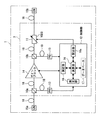
図1は本発明が適用される光伝送システムの動作原理を説明するための図である。この図1に示す光伝送システム1は、波長多重光を伝送するシステムであって、コアネットワーク(CN:Core Network)15a,15bと、伝送路(ファイバ)18と、光増幅器2とをそなえて構成されている。
【0025】
ここで、コアネットワーク15a,15bは、いずれも、大容量の光伝送を行なう基幹回線であり、伝送路18は、光信号を伝送するものである。また、光増幅器2は、伝送路18を伝送する波長多重光を増幅するものである。
以下、光信号の伝送方向は、特に断らない限り、コアネットワーク15aからコアネットワーク15bに向かう方向とする。
【0026】
この光増幅器2は、例えば光信号を増幅するブースタ又は光信号を中継するリピータとして機能するものであって、光カプラ10a,10b,ゲインブロック14,光フィルタ(光バンドパスフィルタ)11,フォトダイオード(光パワーモニタ)13,制御部12をそなえて構成されている。
ここで、光カプラ10aは、伝送路18からの入力光パワーをモニタするための光(モニタ光)を分岐するものであって、入力光を例えば10:1等の分岐比で分岐しその分岐光を出力するものである。また、光カプラ10bは、ゲインブロック14からの出力光パワーをモニタするためのモニタ光を分岐出力するものである。これらの光カプラ10a,10bはいずれも複数の分岐比を設定でき、その分岐比を適切に選択できるようになっている。
【0027】
フォトダイオード13は、モニタ用の光検出器(PD:Photo Detector)であって、ゲインブロック14の入力側および出力側にそれぞれ設けられ、光カプラ10a,10bによって分岐された入力モニタ光パワー(トータル光パワー)および出力モニタ光パワー(トータル光パワー)をそれぞれモニタするものであって、必要なレンジにおいて必要な精度を得られる。フォトダイオード13は、光パワーに応じた電流を、制御部12に設けられた測定手段(以下に述べる測定部19)に入力し、この測定手段がその電流値を測定することによって、制御部12は光パワーを得る。
【0028】
ゲインブロック14は、波長多重光を増幅する増幅媒体であり、希土類ドープファイバ増幅(集中増幅型増幅)又はラマン増幅(伝送路増幅型増幅)により構成される。また、稀土類ドープファイバの一例として、EDFが用いられている。
光フィルタ11は、伝送路18に接続され通過波長特性を可変に設定可能なものであり、可変利得イコライザとして機能している。すなわち、この光フィルタ11は、チューナブルであり、制御部12によって、適切な通過波長特性を設定され、これにより、損失した波長帯域が補償され、また、通過波長特性の形状が波長に対して平坦になるように制御できる。
【0029】
光フィルタ11は、光増幅器2の起動後は、出力光のモニタによりフィードバック制御される。一方、EDFAの利得プロファイルにおいて、実験等によって得られた利得波長特性のポイント間におけるポイントの利得波長特性は、内挿によって得られ、また、利得波長特性を表す曲線の範囲外におけるポイントの利得波長特性は、外挿によって得られる。従って、利得波長特性は予測可能であり、これを用いて、起動前および起動後において、光フィルタ11を設定するのである。
【0030】
さらに、伝送路18のチルト量は微少であり、また、管理者は伝送路長に関する情報を、ネットワークを利用する顧客から得ることができるので、チルト量についても、予測可能である。このため、光増幅器2の動作を開始する前に、管理者は、利得波長特性に基づいて、予め既知の補償量を決定することができる。これにより、光増幅器2を起動する前に、利得波長特性を予測し、光増幅器2に利用する。
【0031】
次に、制御部12は、光フィルタ11の通過波長特性を演算しその演算により得られた通過波長特性の逆特性を光フィルタ11に設定するものであって、測定部19,データベース(保持部又は保持テーブル)17,演算部(演算処理部)16,設定部16aをそなえて構成されている。
ここで、測定部19は、ゲインブロック14の入力側における波長多重光の入力光パワー,ゲインブロック14の出力側における波長多重光の出力光パワーおよびゲインブロック14の入力側における励起光パワー(以下、これらの各パワーを光パワーと称する。)を測定するものである。
【0032】
データベース17は、上記の伝送路18の種類毎の損失波長特性(損失の波長依存性)を示すデータと、ゲインブロック14の入出力パワー又は励起パワーをパラメータとする利得波長特性を示すデータとを保持するメモリ又はテーブルである。例えばシングルモードファイバの損失波長特性は、後に詳述する図6(a)に示すように、損失波長特性として保持されており、また、この損失波長特性は、図6(b)に示すように、シングルモードファイバを用いたEDFAの入出力パワー(A1,B1),(A2,B2)および(A3,B3)をパラメータとして保持されている。
【0033】
具体的には、データベース17は、ゲインブロック14がEDFA等の集中増幅型増幅器を用いているときは、EDFAの入出力パワーをパラメータとした利得波長特性を保持し、また、ゲインブロック14がラマン増幅器の伝送路増幅型増幅器を用いているときは、励起パワーをパラメータとした利得波長特性を保持する。従って、データベース17は、利得波長特性を、増幅器の種類に応じて、保持している。データベース17は、これらの図6(a),図6(b)にそれぞれ示すデータを必須のものとして保持し、また、伝送路長(伝送路長に関する情報)をも保持し、さらに、ゲインブロック14の利得非均一性を補償するデータをも保持する。これらの伝送路長,補償用データにより、損失波長特性を予め予測でき、波長毎に異なる重み付けを補償できる。
【0034】
また、利得波長特性は、シングルモードファイバおよびノンゼロ分散シフトファイバの各損失波長特性の単位距離あたりの値と、エルビウムドープファイバによるEDFAの入力光パワーおよび出力光パワーのそれぞれの値とによって決定される。ここで、シングルモードファイバとは、単一モードの光信号のみが伝送可能であってモード分散(複数モードの光信号が伝送する場合に生じる各速度の相違に起因する伝送帯域の狭小化をいう。)がなく広帯域である。一方、ノンゼロ分散シフトファイバとは、非線形現象を回避するためのものであってファイバのゼロ分散波長帯域と伝送波長帯域とが分離されるようになっている。
【0035】
データベース17の機能は、例えば図5に示す不揮発性メモリ(NVM:Non Volatile Memory)により発揮される。そして、特性データが不揮発性メモリに記録される時期は、例えば光増幅器2が製品として工場から出荷するときである。そして、光フィルタ11を起動するときに、制御部12が、データベース17の特性データを読み取って、その特性データを光フィルタ11に設定するのである。すなわち、制御部12は、伝送路18の種類を、自局に設けられたデータベース17から取得している。なお、データベース17は制御部12の外に設けることもできる。
【0036】
このように、EDFAについては、光増幅器2の入出力光パワーをパラメータとした利得波長特性が保持され、また、利得波長特性は、光増幅器2の種類に対応する複数の利得波長特性が保持されている。
さらに、データベース17は、光増幅器2の起動時(立ち上げ時)と起動後(立ち上げた後)との双方における波長特性を保持することもでき、このようにすれば、光フィルタ11の状態が常時モニタされるので、一層、効率的な光伝送システム1の運用が可能となる。
【0037】
次に、演算部16(図1参照)は、取得された伝送路18の情報と、測定部19にて測定された光パワーと、データベース17に保持されたデータとに基づいて、光フィルタ11の波長特性とは逆の通過逆特性を演算するものである。
この通過逆特性を得るために、演算部16は、上記データベース17から、トータルの光信号としての波長特性を計算する必要がある。演算部16が必要なデータは、(A)入出力の伝送路(ファイバ)の種類(B)入出力伝送路(ファイバ)長および(C)入出力パワーである。
【0038】
すなわち、波長特性(利得波長特性および損失波長特性)はともに、EDFAの入力光パワー(トータルパワー)と、EDFAの利得(トータルパワー)と、伝送路18の種類および伝送路長(伝送路長,スパン長又はファイバスパン長)とによって決定される。また、入力光パワーおよび出力光パワーは、ともに、測定部19によって取得され、伝送路18の種類および伝送路長は、ともに、データベース17に保持されたデータから取得される。
【0039】
そして、設定部16aは、演算部16にて演算された通過逆特性に基づいて光フィルタ11の通過波長特性を設定するものである。なお、演算部16は、光フィルタ11に設けることもでき、光フィルタ11にて演算された結果を制御部12に戻し、制御部12がその結果を用いて制御するようにもできる。
これにより、本発明の光増幅器における通過波長特性制御方法は、波長多重光を増幅するゲインブロック14に接続された測定部19が、ゲインブロック14の入力側における波長多重光の入力光パワーおよびゲインブロック14の出力側における波長多重光の出力光パワーを測定し、測定部19に接続された取得部(32,13)が、伝送路18の種類を取得し、測定部19に接続された演算部16が、測定部19にて測定された光パワーと、取得された伝送路18の種類と、データベース17に保持された上記の伝送路18の種類毎の波長特性を示すデータとに基づいて、伝送路18に接続され通過波長特性を可変に設定可能な光フィルタ11の通過逆特性を演算し、演算部16に接続された設定部19が、演算部16にて演算された通過逆特性に基づいて光フィルタ11の通過波長特性を設定する。
【0040】
また、制御部12は、通過波長特性を光フィルタ11に設定した状態で光フィルタ11を起動させる。従って、データベース17が、集中増幅型伝送路の入力光パワーと出力光パワーとのそれぞれに対応する波長特性を保持し、演算部16が、データベース17に保持された入力光パワーと出力光パワーとのそれぞれに対応する波長特性に基づいて、通過逆特性を演算するのである。
【0041】
このように、初期導入する場合において、光伝送システム1が、波長多重数が少数の状態にて運用されているときに、光フィルタ11は、最適点に近い状態にフィードバック制御されるので制御の簡素化を図れる。
これにより、光フィルタ11は、その起動後においても、モニタ値の測定結果に基づいて、適宜、計算上最適な通過帯域特性に制御される。
【0042】
次に、図2〜図7を参照し、ゲインブロック14がEDFAの場合における通過波長特性制御方法を説明し、図8を参照してゲインブロック14がラマン増幅の場合について説明する。
図2は本発明の第1実施形態に係る光波長多重伝送装置の構成例を示す図である。この図2に示す光伝送システム1aは、波長多重光を伝送するものであって、集中増幅型増幅を行なう光増幅器2aを設けている。また、この光増幅器2aは、EDFA25をそなえ、EDFA25の入力側,出力側に、それぞれ、光カプラ10a,10bを介して、光アイソレータ20を設け、さらに、出力側の光アイソレータ20に、光フィルタ11aが設けられている。また、この光フィルタ11aは、制御部12aによって通過逆特性を設定されるようになっている。これ以外のもので上述した符号と同一の符号を有するものは同一機能を有する。
【0043】
ここで、光アイソレータ20は、主に反射光によるRIN(Relative Intensity Noise:相対強度雑音)の劣化と、反射光によるEDFA25の破壊とを防止するためのものであって、取り外し可能になっている。なお、RINとは、EDFA25に設けられた励起レーザ(励起レーザ25b)が出力する光強度雑音(光強度のゆらぎ)の指標を表し、単位波長あたりの光強度雑音と励起レーザが出力する平均の光パワーとの比で表される。
【0044】
また、EDFA25は、EDF25a,励起レーザ(LD:Laser Diode)25b,光カプラ25cをそなえて構成されている。ここで、EDF25aはエルビウムドープファイバである。また、励起レーザ25bはEDFを励起するためのものであって、例えば1.48μm又は0.98μmの波長の励起光(励起レーザ光)を出力するものである。光カプラ25cは、励起レーザ25bの励起光を主光信号とともにEDF25aに入力するための波長多重用カプラであって、一例としてEDF25aの入力側に設けられている。この光カプラ25cは、EDF25aの出力側又はその入力側および出力側の両方に設けることもできる。
【0045】
次に、光フィルタ11aは通過波長特性(通過帯域特性)を調整可能な光バンドパスフィルタである。図3(a)は光フィルタ11aの模式的な外観図である。この図3(a)に示す光フィルタ11aは、チップ98の上に、波長多重光を導波する複数のファイバグレーティング(FBG:Fiber Bragg Grating)99が一定の光路長に基づく間隔で直列に設けられている。そして、光フィルタ11aが制御されていないときは、波長多重光に含まれる複数の単一波長光が、それぞれ、別個のファイバグレーティング99を通過する。
【0046】
一方、図3(b)はファイバグレーティング99の模式的な外観図であり、この図3(b)に示す光フィルタ11aが制御されているときは、複数の単一波長光が通過する個々のファイバグレーティング99に設けられたヒーターが、設定部16aからの制御信号によって加熱される。
そして、図4(a)はファイバグレーティング99の個々の損失波長特性を示す図であり、個々のファイバグレーティング99の遮断量が表示されている。また、損失波長光(波長λN:ここで、Nは2以上の自然数を表す。)と、その損失波長光の波長λNに隣接する波長の波長光とが結合し、損失波長λNを中心とする波長帯域成分が損失するのである。ファイバグレーティング99のトータルの損失波長特性を図4(b)に示す。
【0047】
このように、ファイバグレーティング99の損失が、温度によって調整できる。なお、この光フィルタ11aの特性は、一例であって、例えば電界強度を制御することによって所望の波長を有する波長光を損失させることもできる。
そして、制御部12a(図2参照)は、光フィルタ11aを制御するためのものである。
【0048】
図5は本発明の第1実施形態に係る制御部12aのブロック図である。この図5に示す制御部12aは、光フィルタ11aを制御するためのフィルタ制御ドライバ回路部97a,データライン用のバス97b,演算用のCPU(Central Processing Unit)97c,光増幅器2aの起動時の手順を保持するブートROM97d,データベース17として波長特性データを保持する複数の不揮発性メモリ97e,各種演算用の複数のRAM97f,制御部12の外部に設けられたモジュール(図示省略)との間において、データを入出力するための入出力インターフェース97gをそなえて構成されている。なお、この図5に示す制御部12aの構成は、後述する他の実施形態および各変形例における制御部12b,12cも同様な構成である。
【0049】
このデータベース17に保持された特性データについて、さらに詳述する。
図6(a)〜図6(d)は、本発明の第1実施形態に係る波長特性データの一例を示す図であり、図7は本発明の第1実施形態に係る通過逆特性の演算例を説明するための図である。不揮発性メモリ97eは、損失波長特性と利得波長特性とのそれぞれのデータであって、図6(a)に示す伝送路18(例えばシングルモードファイバ)の損失波長特性データは、損失波長特性を例えば5000分割したデータからなる。また、不揮発性メモリ97eは、図6(b)に示す波長特性データは、ゲインブロック14(例えばEDFA)の利得波長特性データであって、カーブ(うねり)を有する。この曲線は、波長依存特性を5000分割したデータからなり、この5000分割されたデータが、EDFA25の入力光パワーと出力光パワーとのペアをパラメータとして複数(例えば3種類)の利得波長特性として保持されているのである。なお、分割数5000は器材の性能等に起因し、種々の分割数を用いることができる。
【0050】
さらに、図6(c)に示す特性データは、図6(a)および図6(b)に示す損失波長特性データと利得波長特性データとを加算した後の損失波長特性データを示している。
そして、演算部16は、フォトダイオード13,測定部19等によって測定された入力光パワーと出力光パワーとについて、データベース17に保持された光パワーをパラメータとした波長特性データから内挿することによって、所望の入力光パワーおよび出力光パワーについてのEDFAの利得波長特性を計算する。
【0051】
図7は本発明の第1実施形態に係る内挿を説明するための図である。この図7に示す曲線1は、入力光パワーA1,出力光パワーB1のときの利得波長特性であり、曲線2は、入力光パワーA3,出力光パワーB3のときの利得波長特性である(ここで、A1>A3およびB1>B3とする。)。また、曲線1,2間における利得波長特性は、予めデータベース17には保持されていない。ここで、測定部19が、入力光パワーA4,出力光パワーB4を得ると、演算部16は、5000分割された特性データのうちの例えば波長λXについて得られた特性データに基づいて、入力光パワーA4,出力光パワーB4についての特性データCを内挿する。そして、演算部16は、5000個の特性データについて、それぞれ、曲線1,2間に内挿し、これにより、入力光パワーA4,出力光パワーB4のときの利得波長特性を表す曲線3を得るのである。
【0052】
さらに、光フィルタ11aの制御値の計算にあたり、演算部16は、内挿計算により得たEDFA25の利得波長特性データと、図6(a)に示す損失波長特性データとを加算して、図6(c)に示す損失波長特性データを得て、そして、この図6(c)に示す損失波長特性と逆の逆特性を計算する。図6(d)は逆特性データの一例を示す図である。
【0053】
具体的には、計算された波長特性データ値がGi(dB)であるとき、光フィルタ11aの制御目標値Liは、「Gi(dB)+Li(dB)=0」を満たすLiである。さらに、実際の制御値は、「min{|Li|}=Lm」と定義したときに、「L−Cont−I=Li+Lm」により定義される値である。そして、制御部12は、この制御値L−Cont−Iを光フィルタ11aに設定することにより、光増幅器2aから出力される光信号の波長特性を平滑化するのである。
【0054】
なお、後述する他の実施形態および各変形例においても、特に断らない限り、この計算方法を利用している。
このような構成によって、トータルとしての波長特性を計算する場合、演算部16は、与えられた入出力側の伝送路18の種類および入出力ファイバの伝送路長と、入力モニタ光パワーおよび出力モニタ光パワーとを得るとともに、設定目標出力値からデフォルトのゲインブロック14の利得波長特性および伝送路18の損失波長特性をデータベース17から得る。そして、制御部12aは、光フィルタ11aの通過波長特性を、その演算された波長特性の逆特性に設定し、光フィルタ11aがその逆特性を設定された状態で起動する。そして、光フィルタ11aが起動した後、制御部12aが、出力光パワーおよび入力光パワーの各モニタ値の測定結果を用いて、光フィルタ11aを、適宜、適切な通過帯域特性に制御し、これにより、光フィルタ11aの通過帯域特性が最適化される。
【0055】
また、光フィルタ11aに逆特性データを設定するタイミングは、種々のタイミングで可能であり、一例として、以下に述べる制御部12の制御シーケンスのいずれかにおいて設定可能である。
制御部12は、光増幅器2aが起動する前においては、まず、入力光の有無を判定し、入力光が入力されたと判定すると光増幅器2aを起動する。そして、制御部12は、出力光パワーが安定しているか否かを判定する。ここで、出力光パワーが安定している場合、測定部19により入力光パワーと出力光パワーとを測定し、これらの入力光パワーと出力光パワーとに基づいて、演算部16により、光フィルタ11aの通過帯域特性を計算する。そして、制御部12は、設定部16aにより、光フィルタ11aの通過逆特性を設定する。
【0056】
一方、制御部12は、光増幅器2aの起動後においては、入力光の有無を判定せずに、出力光パワーの安定を判定し、入出力光パワーを測定し、そして、演算部16による演算と、光フィルタ11aの設定とを行なう。
従って、光フィルタ11aの設定は、常時起動状態の場合においても、実施可能である。
【0057】
このように、光増幅器2aは、光スペクトラムアナライザ等の追加部品を用いずに、出力光の波長特性を平滑化でき、冗長な励起光パワーを抑制できる。これにより、光スペクトラムアナライザを用いて通過帯域の調整時に必要なダミー光が不要となる。
従って、装置の小型化,低コスト化が図れ、例えば対向局としての光増幅器2aおよび光伝送システム1aの価格の低廉化を実現できる。
【0058】
そして、このように、光フィルタ11aの起動時における制御目標値を適切に設定できるので、光伝送システム1aが起動した時刻と、例えば対向局間の信号疎通が開始した時刻との時間を短縮化できる。
このようにして、光伝送システム1aは、システムの増設又は減設時の制御システム(例えば光スペクトラムアナライザ)への擾乱を回避でき、また、増設・減設工事の対象となる波長以外の波長を有する光信号への悪影響を防止でき、これにより、動作の安定化が図れる。
【0059】
(B)本発明の第2実施形態の説明
第2実施形態においては、ゲインブロック14(図1参照)が、ラマン増幅器により構成された場合について説明する。
図8は本発明の第2実施形態に係る光波長多重伝送装置の構成例を示す図である。この図8に示す光伝送システム1bは、波長多重光を伝送するものであって、ラマン増幅機能を有する伝送路(ラマン増幅器)18aと、励起光出力と光パワーモニタとを行なう光増幅器2bとをそなえて構成されている。この光増幅器2bの制御部12bは、光フィルタ11aの通過波長特性を演算しその演算により得られた通過波長特性の逆特性を光フィルタ11aに設定するものであって、測定部19,データベース17,演算部16,設定部16aをそなえて構成されている。
【0060】
ここで、測定部19は、ゲインブロック14の入力側における励起光パワーを測定するようになっている。そして、ゲインブロック14が、ラマン増幅可能な伝送路18aを用いて増幅するとともに、設定部16が、光フィルタ11aの起動後において、ラマン増幅可能な伝送路18aの励起光パワーに基づいて通過波長特性を設定するようになっている。従って、光フィルタ11aの起動前後において、迅速な波長特性制御と効率的な光増幅とが可能となる。例えば、ネットワークの拡張時において、既に管理者が顧客等に割り当てた光波長の帯域を変更せずに拡張できる。
【0061】
また、データベース17は、各励起波長毎のラマン効率データと、伝送路18,18aの損失波長特性データとを保持している。このデータベース17は、伝送路18,18aの種類毎の損失波長特性を保持するとともに、励起光パワーをパラメータとした利得波長特性を保持する。さらに、この利得波長特性は、光増幅器11aの種類に対応して保持されている。
【0062】
また、利得波長特性は、シングルモードファイバおよびノンゼロ分散シフトファイバについて損失波長特性の単位距離あたりの値と、ラマン増幅のための励起光パワーとによって決定されるものである。すなわち、データベース17は、伝送路増幅型の伝送路18aの励起光パワーに対応する波長特性を保持し、そして、演算部16が、データベース17に保持された励起光パワーと測定部19にて測定された出力光パワーとのそれぞれに対応する波長特性に基づいて、通過逆特性を演算するようになっている。これにより、伝送路18の種類にかかわらず、容易に損失波長特性を得ることができる。また、光フィルタ11aは、起動時および起動後のいずれにおいても制御される。
【0063】
一方、ゲインブロック14が、ラマン増幅可能な伝送路18aを用いて増幅するとともに、設定部16aが、光フィルタ11aの起動後において、ラマン増幅可能な伝送路18aの励起光パワーに基づいて通過波長特性を設定する。これにより、光増幅器の起動前後において適切に波長特性を制御できる。
さらに、ラマン増幅器18aは、十分なラマン効果を生じうるファイバであって、ゲインブロック14(図1参照)として機能している。このラマン増幅器18aの利得プロファイルの形状は、伝送路18aのラマン効率と、相異なる波長の励起光を出力する複数の励起レーザパワーとによって決定する。なお、ラマン増幅用のファイバは、集中ラマン増幅する場合は、DCF(Dispersion Compensation Fiber:分散補償ファイバ)が用いられる。また、図8に示すもので、上述したものと同一符号を有するものは同一機能を有する。
【0064】
このような構成によって、演算部16は、測定部19によって測定された励起光パワー値と、与えられた入力側の伝送路18aの種類および伝送路長と、設定目標出力値とを用いて、デフォルトのゲインブロック14の利得波長特性および伝送路18aの損失波長特性を、データベース17のデータによって演算し、光フィルタ11aの制御値を得る。
【0065】
そして、制御部12bは、光フィルタ11aの通過逆特性を設定し、その通過逆特性に設定した状態で光フィルタ11aを起動させる。光フィルタ11aが起動した後、制御部12bは、励起光パワーと入力光パワーのモニタ値の測定結果とに基づいて、光フィルタ11aの通過帯域特性を適宜、適切な特性に制御し、これにより、光フィルタ11aの通過帯域特性が最適化される。
【0066】
このように、光増幅器2bは、光スペクトラムアナライザ等の追加部品を用いずに、出力光の波長特性を平滑化でき、冗長な励起光パワーの出力を抑制できる。また、ダミー光が不要となり、光増幅器2bおよび光伝送システム1bの価格の低廉化が可能となる。そして、光伝送システム1bの起動時において、例えば中継局間が相互に信号疎通できるまでの時間を短縮化できる。
【0067】
このようにして、光伝送システム1bの増設又は減設時において、制御システムへの擾乱を回避でき、光伝送システム1bの安定化が図れる。
(C)本発明の第3実施形態の説明
第3実施形態は、第1実施形態および第2実施形態の変形例であって、光増幅器2a又は光増幅器2bを有する光伝送システム1a又は1bにおいて、入力側に接続された伝送路18の種類と伝送路長とを、上流からのSV(Supervisory:監視)光から得るものである。このSV光は、伝送路18の種類および伝送路長等等の情報を含み、波長多重光に割り当てられる波長と異なる波長を有する光信号である。
【0068】
図9は本発明の第3実施形態に係る光伝送システムの概略的な構成図である。この図9に示す光伝送システム1cは、光波長多重端局(以下、端局と称する。)30,31と、ゲインブロック14と、光増幅器2a(又は2b)に含まれる光カプラJ1〜J8と、合分波器32とをそなえて構成されている。また、光信号の伝送方向は、端局30aから端局31aに向かう第1の方向と、その逆の第2の方向とがある。
【0069】
そして、伝送路18に接続された各中継局が、自局の出力側に接続されている伝送路18のファイバ種類および伝送路長を、下流局(端局を含む。)に対して、SV光を用いて伝送し、下流局が、そのSV光に挿入された情報に従って、光フィルタ11aの波長特性を調整する。ここで、ゲインブロック14は、EDFA又はラマン増幅を表す。
【0070】
また、端局30,31は、それぞれ、光信号を終端するものであって、SV光を送信する送信器30a,31bと、SV光を受信する受信器30b,31aとをそなえて構成されている。また、合分波器32は、第1の方向については、伝送路18からSV光を抽出するとともに、第1の方向と逆の第2の方向については、伝送路18にSV光を合波して出力するものである。
【0071】
これにより、端局30は、伝送路18の種類および伝送路長等の情報を含むSV光を隣接する光増幅器2a(2b)に対して送信し、そのSV光は合分波器32にて分岐される。分岐されたSV光は、フォトダイオード13にて光・電気変換され、その変換された電気信号に含まれる情報が、受信処理部(図示省略)にてデコードされる。換言すれば、伝送路18の種類および伝送路長は、合分波器32,フォトダイオード13および受信処理部の協働により、取得部(32,13)として機能しており、また、この取得部(32,13)は、ゲインブロック14に接続された伝送路18の種類,伝送路長を、伝送路18の上流側からのSV光、又は伝送状況を監視する装置監視系(後述する図12参照)から得るものである。これにより、更新された情報が効率よく利用される。
【0072】
また、光増幅器2a(2b)の演算部16は、受信光に含まれるデータに基づいて、第1の方向側についての通過逆特性を演算するとともに、設定部16aが、データベース17に保持されたデータに基づいて、伝送路18の第1の方向側部分についてその通過逆特性を設定するようになっている。
そして、各光増幅器2a(2b)は、自局の出力側に接続されている伝送路18の種類および伝送路長に関する情報をSV光に挿入して下流局に対して送信し、下流局は上流局からのSV光に含まれる情報に基づいて、出力光パワーの出力値を調整する。そして、各下流局は、伝送路18の種類および伝送路長等の情報を、SV光に挿入し、そのSV光を隣接する下流局に対して送信し、端局31の受信部31aにおいて受信処理される。また、第2の方向の伝送についても同様である。
【0073】
さらに、伝送路18に接続された各中継局も、上流側からの光信号をデコードし、また、伝送路18の種類および伝送路長に関する情報を、SV光に挿入して下流側に送信する。
このように、光フィルタ11aの損失波長特性の計算に必要なデータの取得方向は、種々のバリエーションがあるので、外部からの擾乱の発生に対して影響されにくくなる。
【0074】
なお、図9に示す光伝送システム1eは、後述する第5実施形態において説明する。
このような構成によって、光伝送システム1cにおける通過波長特性制御が行なわれる。
図10は本発明の第3実施形態に係る通過波長特性制御を説明するためのフローチャートである。光増幅器2は、上流局からのSV光が入力されない間は、励起レーザ25bの発光を停止しており(ステップA1)、上流局からのSV光を受信すると、SV光に含まれる情報データをデコードする(ステップA2)。そして、ステップA3において、取得部(32,13)は、伝送路18の種類および入力側の伝送路長の情報等が全て受信されると、その情報が変化されているか否かを判定し、変化がないときは、Nルートを通り、ステップA2における受信処理を行なう一方、ステップA3において変化があるときは、Yルートを選択する。ここで、演算部16は、光増幅器2の内部のデータベース17に保持された損失波長特性データを用いて、光増幅器2の波長特性データを内挿して計算し(ステップA4)、また、設定部16aが光フィルタ11aに特性データを設定することにより、光フィルタ11aが制御される(ステップA5)。
【0075】
このように、第3実施形態においても、第1実施形態および第2実施形態にて得られた効果と同一の効果が得られる。
また、光伝送システム1cにおける通過波長特性制御は、1台の局が複数の伝送路18に接続されて1:M(Mは2以上の自然数を表す。)の冗長システムが構成されている場合についての動作を説明する。なお、冗長システムとは、例えば図11に示すように、光信号を伝送している現用伝送路18bと、光信号を伝送せずに現用伝送路18bの切断又は保守のための停止の場合における予備用として確保されている複数の予備用伝送路18cとから構成されていることが知られている。
【0076】
このような構成によって、現用伝送路18bにおいて、切断等の障害が発生した場合、下流局は、自局の受信処理部(図示省略)に設けられたセレクタを用いて現用伝送路18bを複数の予備用伝送路18cのうちのいずれかのものに切り替える。そして、現用伝送路18bを切り替えた下流局は、伝送路18と1:1対応している上流局から、伝送路18の種類および伝送路長等の情報をデコードし、光フィルタ11aの通過波長特性を制御する。
【0077】
これにより、中継局からの出力光特性が平滑化され、支障移転等が生じた場合において、迅速に光伝送システム1cの正常化が可能となる。
(D)本発明の第4実施形態の説明
第4実施形態における光伝送システムにおいては、各局と接続されたネットワークマネージメントシステム(Network Management System:NMS)が設けられ、このNMSが、各局(単局をも含む。)の出力側の伝送路18の種類および伝送路長に関する情報を各局に通知し、各局の演算部16は、これらの情報に基づいて光フィルタ11aの特性を計算する。そして、各局の光フィルタ11aは、各局の設定部16aによってその計算された特性を設定され、また、その特性が調整される。そして、NMSは、EDFAおよびラマン増幅のいずれについても通知できるようになっている。
【0078】
図12は本発明の第4実施形態に係る光伝送システムの概略的な構成図である。この図12に示す光伝送システム1dは、NMS33と、複数の装置監視系(装置監視システム)34a〜34cとを設けている。ここで、NMS33は、トラフィックを制御するものであって、通常、各局とは別個の場所に設けられ、各局の伝送状況を集中的に監視する。この監視機能は、監視用のソフトウェアアプリケーションのうちの主に上位レイヤ側を監視するためのコントロールレイヤによって発揮される。
【0079】
また、ゲインブロック14は、EDFAにより構成されたものであり、このゲインブロック14が伝送路18を介して、複数、多段に接続されている。なお、ゲインブロック14が設けられている光増幅器2については表示を省略している。
さらに、装置監視システム34a〜34cは、各光増幅器2(ゲインブロック14)の伝送状態を監視しその伝送状態をNMS33に報告するとともに、各光増幅器2について伝送路18の種類および伝送路長等を設定するものである。これらの装置監視システム34a〜34cは、伝送路18の第1の方向および第2の方向について個別に光フィルタ11a(図示省略)を設定可能になっている。例えば、装置監視システム34aは、第2の方向のゲインブロック14(又は光増幅器2)について設定し、装置監視システム34bは、第1の方向および第2の方向の双方についてゲインブロック14(又は光増幅器2)を設定する。同様に、装置監視システム34cは、第2の方向のゲインブロック14(又は光増幅器2)について設定する。
【0080】
これにより、各中継局としてのゲインブロック14は、装置監視システム34a〜34cによって、伝送路18の種類および伝送路長等を設定され、かつ、各装置監視システム34a〜34cは、NMS33から伝送路18の種類等に関する情報を得る。
また、演算部16は、受信光に含まれるデータに基づいて、第1の方向側についての通過逆特性を演算するとともに、設定部16aが、データベース17に保持されたデータに基づいて、伝送路18の第1の方向側部分についてその通過逆特性を設定する。この演算部16が、自局からのデータに基づいて、第1の方向側についての通過逆特性を演算するとともに、設定部16aが、データベース17に保持されたデータに基づいて、伝送路18の第1の方向側部分についてその通過逆特性を設定するのである。
【0081】
このような構成によって、NMS33および装置監視システム34a〜34cは、それぞれ、光増幅器2を制御する。
図13は本発明の第4実施形態に係る通過波長特性制御を説明するためのフローチャートである。光増幅器2は、励起レーザ25cの発光を停止している状態(ステップB1)において、装置監視システム34aによって伝送路18の種類等を設定されると(ステップB2)、取得部(32,13)は、伝送路18の種類等を全て受信したか否かを判定し、その情報が変化されているか否かを判定する(ステップB3)。ここで、変化がないときは、Nルートを通り、ステップB2に戻り、変化があるときは、Yルートを通り、演算部16は、内部データベース17に保持された損失波長特性データを用いて、光増幅器の波長特性データを内挿して計算し(ステップB4)、また、設定部16aが光フィルタ11aに特性データを設定することにより、光フィルタ11aが制御される(ステップB5)。
【0082】
これにより、上流局が、伝送後の損失波長特性を予め考慮し、損失の波長特性データに、波長毎に異なる重み付けを加算して、その損失の波長特性データを下流局に送信する。
従来の下流局は、伝送光に含まれる波長(チャネル)のうちの一番劣化した波長についてSN比(Signal Noise Ratio)を改善するように動作させていた。これに対して、本下流局は、最も劣化した波長を改善しないで、SN比が平均してよくなり、下流局にて受信レベルのマネージメントがされていない光信号を増幅するよりも良好な伝送特性を得ることができる。
【0083】
なお、第4実施形態においては、ゲインブロック14がラマン増幅器を用いて構成されることができ、また、その動作は、図13に示すフローチャートと同様なフローチャートであるので、重複する説明を省略する。
さらに、以下に示す3種類の変形態様を用いて実施することもでき、これらの変形態様はEDFAおよびラマン増幅のいずれをも適用して構成可能である。
【0084】
第1の変形例として、各中継局が、伝送路18の損失波長特性を送信側の伝送路18について補償するように制御し、また、出力側の伝送路18の情報については、装置監視システム34a〜34cからのSV光に挿入された情報を用いて設定するようにもできる。
第2の変形例として、各中継局が、伝送路18の損失波長特性については送信側の伝送路18について補償するように制御し、また、出力側の伝送路18の情報については、下流側対向局からのSV光に挿入された情報を用いて設定するようにもできる。
【0085】
第3の変形例として、各中継局が、伝送路18の種類および伝送路長については、上流局からのSV光に挿入された情報を用いて設定するようにもできる。
(E)本発明の第5実施形態の説明
第5実施形態においては、ゲインブロック14が、利得一定制御の希土類ドープファイバからなり、このゲインブロック14が、2段以上接続されている。
【0086】
図14は本発明の第5実施形態に係る光伝送システムの動作原理を説明するための図である。この図14に示す光伝送システム1fは、伝送路18を伝送する波長多重光を増幅する光増幅器2cをそなえ、この光増幅器2cは、2段のゲインブロック14を有する。これらのゲインブロック14は、波長多重光を増幅するものであって、EDFAからなる。なお、ゲインブロック14は、ラマン増幅を用いることもできる。なお、ゲインブロック14は2段階に限らず、2段以上の複数のゲインブロック14を接続するようにもできる。
【0087】
また、光フィルタ11aは、その特性についてチューナブルであり、2段のゲインブロック14の間に設けられている。
そして、演算部16が、集中増幅型伝送路の利得を一定制御するように通過逆特性を演算する。なお、この図14に示す符号のうちの上述したものと同一の符号を有するものは同一の機能を有する。
【0088】
このような構成により、演算部16は、データベース17のデータを用いて、光フィルタ11aの通過波長特性の逆特性を計算し、設定部16aがその逆特性を光フィルタ11aに設定して、光増幅器2cを起動させる。また、光増幅器2cの起動後は、演算部16が出力光パワーと入力光パワーとのそれぞれについて、モニタ値を測定して、その測定結果およびデータベース17に保持されたデータに基づいて、計算上適切な通過帯域特性を演算し、その特性を光フィルタ11aに設定する。
【0089】
これにより、通過帯域特性が最適化される。また、光フィルタ11aの起動前と起動後とのいずれの場合においても、適切な通過帯域特性を設定することができる。
さらに、飽和状態動作のEDFA25が複数多段に接続されており、所望の利得を得られる。また、NF(Noise Figure:雑音指数)等の特性の変動は、入力光パワーが変動した場合において減少させることができる。
【0090】
次に、ゲインブロック14がEDFAの場合における通過波長特性制御方法について図15を参照して説明する。
図15は本発明の第5実施形態に係る光伝送システムの概略的な構成図であって、図14に示す光伝送システム1hの実施形態例である。この図15に示す光増幅器2dは、光フィルタ11aの出力側に、励起レーザ25bおよび光カプラ25cを有するゲインブロック26が接続されている。また、このゲインブロック26から出力された光信号はモニタ用に分岐され、その分岐光は、制御部12aに入力されるようになっている。なお、この図15に示すもので、上述した符号と同一の符号を有するものは同一機能を有する。さらに、ゲインブロック26は2段以上接続してもよい。
【0091】
これにより、ゲインブロック26の光カプラ25cにおいて、励起レーザ25bが出力した励起光と、光フィルタ11aからの出力光とが合波され、その合波された光信号は、コアネットワーク15bに伝送される。また、ゲインブロック26からの出力光のうちの分岐された分岐光は、フォトダイオード13にて電気信号に変換され、その電気信号が制御部12aに入力される。そして、制御部12aにて通過逆特性が光フィルタ11aに設定される。
【0092】
このように、ゲインブロック26が複数段に接続されている場合においても、特性データの安定化が図れる。
(F)本発明の第6実施形態の説明
上記の第1実施形態の変形態様として、光スペクトラムアナライザを併用させることもでき、光伝送システム1hが動作している間に、設定部16aが設定した損失波長特性(又は利得波長特性)が典型値(設定した最適値)からずれた場合において、その差分が微小な場合には、補償するようにもできる。図16および図17を用いて制御精度を向上させる方法について説明する。
【0093】
図16は本発明の第6実施形態に係る光伝送システムの動作原理を説明するための図である。この図16に示す光伝送システム1hに設けられた光増幅器2eは、光フィルタ11aの出力側に伝送路18,光カプラ10bをそれぞれ介して、光スペクトラムアナライザ27が設けられている。この光スペクトラムアナライザ27は、光増幅器2eから出力される光信号について、光信号に含まれる光スペクトルと、出力光パワーとをそれぞれ、モニタし測定するものである。
【0094】
このような構成によって、制御部12aの設定部16aが光フィルタ11aの特性データの設定が完了した後において、光スペクトラムアナライザ27は、サービス対象の波長をモニタし続けて、制御部12aは、設定部16aが設定した光フィルタ11aの波長特性が適切か否かを判定する。そして、制御部12aは、伝送路18の特性と、設定部16aが設定した典型値との差分を補正する。
【0095】
これにより、光フィルタ11aに設定する逆特性が微調整され、制御精度が向上する。また、このように、制御部12aが伝送路18の特性の微小な典型値からの差分を補正することにより、波長毎の伝送特性の均一化および向上が図れる。
また、図17は本発明の第6実施形態に係る光伝送システムの概略的な構成図であって、この図17に示すEDFA25は、図16に示すゲインブロック26に相当するものである。
【0096】
これにより、光伝送システム1iにおいて、光フィルタ11aからの出力光は、光カプラ10aにて分岐され、その分岐光の波長およびパワーがともにスペクトラムアナライザ27にてモニタされる。そして、制御部12aは、伝送路18の特性が、予め設定した損失波長特性から微少にずれた場合に、そのずれを補正する。
【0097】
このように、微少な値のずれがモニタされ、そのずれが補正されるので、制御精度が向上する。
(G)本発明の第7実施形態の説明
第7実施形態においては、光増幅器の接続数が複数の場合について説明する。図18は本発明の第7実施形態に係る光伝送システムの動作原理を説明するための図であって、この図18に示す光伝送システム1iは、光増幅器2gをそなえ、この光増幅器2gは、2段のゲインブロック14と、制御部12cとをそなえて構成されている。ここで、前段ゲインブロック14(コアネットワーク15a側のもの)の出力光は、フォトダイオード13を介して、光・電気変換され、その変換された電気信号が、制御部12cに入力されている。さらに、後段ゲインブロック14(コアネットワーク15b側のもの)の出力光は2カ所にて分岐されている。すなわち、後段ゲインブロック14の出力光は、光カプラ10cにて分岐され、その分岐光はフォトダイオード13を介して制御部12cに入力される。光カプラ10cにて分岐された後の出力光は、さらに、光カプラ10dにて分岐され、その分岐光は、光ペクトラムアナライザ27によってモニタされている。従って、後段ゲインブロック14からの出力光は、2種類のモニタ値として、制御部12cに入力されるようになっている。
【0098】
図18に示す光フィルタ11aは、2種類のゲインブロック14の間に設けられ、増幅,利得制御,増幅の3種類が1単位となっているが、この単位は、複数にすることもできる。また、この単位は、一個の光フィルタ11aと3個以上のゲインブロック14とから構成することもできる。
また、図19は本発明の第7実施形態に係る光伝送システムの概略的な構成図であって、EDFAを用いてゲインブロック14が構成された場合のものである。
【0099】
この図19に示すEDFA25は、前段ゲインブロックとして機能し、また、EDFA26は、後段ゲインブロックとして機能している。さらに、EDFA26の出力光は、光カプラ10bを介して、光スペクトラムアナライザ27に入力され、この光スペクトラムアナライザ27にて得られたモニタ波長,モニタ波長のパワー等の情報データが、制御部12cに入力されるようになっている。すなわち、制御部12cに入力されるデータは、EDFA25に入力される入力光パワーと、出力光パワーと、EDFA26の出力光パワーと、EDFA26の出力光のモニタ波長等をそれぞれ光・電気変換したものが入力されるのである。
【0100】
このような構成によって、光増幅器2hに入力された光信号は、EDFA25にて増幅されるとともに、このEDFA25の前後における光パワーがモニタされて、各モニタ値が制御部12cに入力される。そして、EDFA25の損失波長特性が調整され、EDFA25から出力される光信号は、その波長プロファイルが適切に補償された後のものである。この光フィルタ11aからの出力光は、EDFA26にてさらに増幅され、その増幅された光信号の一部の光信号は、光カプラ10cにて分岐されてモニタされる。また、EDFA26からの出力光に含まれる波長およびパワーは、いずれも、スペクトラムアナライザ27にて測定されて、それらの測定結果が制御部12cに入力され、これにより、制御精度が向上する。
【0101】
このように、複数のゲインブロック14が、いずれも、EDFAにより構成されているので、飽和状態動作の光増幅器2が複数接続され、所望の利得を出力可能な光中継装置を構成することができ、また、NF等の特性の入力光パワーに対する変動を減少させることができる。
なお、第1の変形例として、演算部16が、光増幅器2gに接続された伝送路18の種類,伝送路長および伝送波長数の各情報を上流局からのSV光から受信するようにもできる。
【0102】
また、第2の変形例として、演算部16が、伝送路18の損失波長特性については、送信側の伝送路18について補償するように制御し、また、伝送波長数,出力側の伝送路18については、それぞれ、上流局対向局,下流側対向局からのSV光に含まれる情報に基づいて設定することもできる。
(H)本発明の第8実施形態の説明
光フィルタ11aの特性を一層精密に補償するためには、データベース17が波長数情報を保持し、また、制御部12a(又は12b,12c)が、ゲインブロック14の利得の非均一性を補償することによって、補償精度を向上させることができる。
【0103】
図20は本発明の第8実施形態に係る光伝送システムの概略的な構成図であって、この図20に示す光信号の伝送方向は、第1の方向(コアネットワーク15aからコアネットワーク15bに向かう方向)と第2の方向(コアネットワーク15bからコアネットワーク15aに向かう方向)との2種類がある。そして、これらの2種類の伝送路18において、各中継局は、それぞれ、波長多重光およびSV光の両方を伝送するようになっている。また、SV光に挿入されるデータ内容は、入力側に接続されたファイバ種類,伝送路長および波長数(波長多重数)のそれぞれであって、これらの少なくとも3種類が上流側の中継局から下流側の中継局に対してSV光を用いて伝送される。
【0104】
なお、この図20に示す光増幅器2は、図1等に示す光増幅器2と同一であり、また、EDFAおよびラマン増幅のいずれをも適用可能である。
次に、この図20に示す光増幅器2において、光フィルタ11aの通過逆特性の計算方法について説明する。
演算部16(図示省略)の演算対象は、入力側ファイバのWDLと、SRSの発生量と、EDFAのWDGとである。すなわち、演算部16は、波長多重数データと誘導ラマン散乱効果による損失波長特性とを対応づけたデータに基づいて、通過逆特性を演算する。そして、これらを演算するために必要なデータは、対向局からのSV光と、自局の入力光および出力光とから取得するようになっている。
【0105】
具体的には、光増幅器2は、対向局からのSV光をデコードしそのSV光に含まれる▲1▼入力側の伝送路の種類▲2▼伝送路長▲3▼運用している波長数を取得し、かつ自局の光増幅器2の入力パフォーマンスモニタ値および出力パフォーマンスモニタ値に基づいて、演算対象(入力側ファイバのWDLと、SRSの発生量と、EDFAのWDG)を計算し、これらの値を補正するように光フィルタ11aを制御する。
【0106】
換言すれば、演算部16は、上流側(第1の方向側)からの受信光に含まれる上流側に設けられた上記の伝送路18の種類毎の損失波長特性を示す第1データと、下流側(第2の方向側)からの受信光に含まれる波長多重数データとに基づいて、通過逆特性を演算するとともに、設定部16aが、伝送路18の上流側部分の通過波長特性を設定する。これにより、可変利得イコライザの通過逆特性の計算が簡略化されるのである。
【0107】
次に、損失波長特性の制御方法例として3種類の態様について説明する。
まず、第1は、光フィルタ11aの特性制御にあたり、隣接する光増幅器2間がいずれもSV光を用いて通信する。各光増幅器2は、それぞれ、上流局における光スペクトラムアナライザ27が得たモニタ値を基準として損失波長特性を微調整する。各光増幅器2は、相互に、その微調整が完了したことを示す完了メッセージを送受信し、そして、この完了メッセージを受信した上流側中継局から順に、適切な値に、各光増幅器2の光フィルタ11aを微調整する。
【0108】
また、第2は、第1の構成と同一構成において、演算部16が、ファイバ情報を上流局からの情報を用いずに、出力側の対向局からの情報又は自局が自局の光増幅器2に設定した情報(例えば出力側の▲1▼伝送路18の種類▲2▼伝送路長▲3▼運用波長数)を直接的に用いて、出力側ファイバのWDLおよびSRS発生量を計算する。さらに、演算部16は、自局の光増幅器2の入力パフォーマンスモニタ値および出力パフォーマンスモニタ値からWDGを計算し、これらを補正するように光フィルタ11aを制御する。そして、制御部12は、下流側の対抗局に入力される波長多重光をデコードして、波長多重信号のSN比が均一となるように制御し、この制御が実施された後、下流側対向局の光スペクトラムアナライザ27によって入力光信号の波長毎のパワーモニタ値をSV光に挿入してその挿入したSV光を隣接する中継局に対して転送し、これにより、微調整する。
【0109】
さらに、第3に、演算部16は、下流側対向局のスペクトラムアナライザ27によるモニタ値を使用せずに、自局のスペクトラムアナライザ27のモニタ値と予め計算して得た設定目標値とに基づいて、ずれを補正するように微調整する。このように、損失波長特性の制御方法が、例えば3種類の態様を有するので、伝送状況に応じて、適切な光フィルタ11aの損失波長特性が制御される。
【0110】
このような構成によって、第8実施形態における波長特性の制御が実施される。
図21は本発明の第8実施形態に係る通過波長特性制御を説明するためのフローチャートである。光増幅器2は、励起レーザの発光を停止している状態(ステップC1)において、上流局からのデータを受信すると(ステップC2)、取得部(32,13)が、伝送路18の種類等を全て受信したか否かを判定し、その情報が変化されているか否かを判定する(ステップC3)。ここで、変化がないときは、Nルートを通り、ステップC2に戻り、変化があるときは、Yルートを通り、演算部16は、内部データベース17に保持された損失波長特性データを用いて、光増幅器2の波長特性データを内挿して計算し(ステップC4)、また、設定部16aが光フィルタ11aに特性データを設定することにより、光フィルタ11aが制御される(ステップC5)。
【0111】
さらに、スペクトラムアナライザ27は、スペクトラムをモニタすることにより測定し(ステップC6),演算部16は、このスペクトラムを用いて、逆特性を計算し(ステップC7)、光フィルタ11aを制御する(ステップC8)。
そして、光増幅器2は、再度、待ち状態になり、上流局からのデータを受信すると(ステップC9)、伝送路18の種類と入力側の伝送路長と波長数とが全て受信されたか否かを判定し、かつそれらのデータ値の変化の有無を判定する(ステップC10)。ここで、伝送路18の種類等を全て受信し、かつ変化がないときは、Yルートを通り、ステップC4の処理をする。一方、伝送路18の種類等を全て受信せず、又は変化があるときは、Nルートを通り、ステップC6からの処理をする。
【0112】
このように、本構成および制御が用いられることによって、演算部16は、伝送路18自身が製造される時の品質の不均一性を吸収できる。また、EDFA25等の経年劣化等が生じることによって、典型値から微小にずれが生じた場合においても、演算部16は、その初期設定値からのずれを吸収できる。
このようにして、波長毎の伝送特性の均一化、向上が図れる。また、このようにして、光部品のうちの経年劣化が生じるものが設けられている場合においても、劣化に起因するずれを効率的に吸収できる。
【0113】
(I)本発明の第9実施形態の説明
第9実施形態においては、ラマン増幅器を用いて、ゲインブロックを構成する場合にその損失波長特性を調製するために、一層精度の高い制御を行なう方法について説明する。
図22は本発明の第9実施形態に係る光伝送システムの動作原理を説明するための図であって、この図22に示す光伝送システム41aは、ラマン増幅による増幅を行なう光増幅器2iをそなえて構成されている。このラマン増幅の機能は、伝送路18,励起レーザ25b,光カプラ25cが協働することによって発揮される。また、制御部12bは、光増幅器2iの入力側の励起レーザ25bの出力光パワーを制御するとともに、光増幅器2iの出力側に設けられた光フィルタ11aの損失波長特性を制御するものである。なお、図22に示す符号のうち、上述したものと同一の符号を有するものは同一の機能を有する。
【0114】
また、光フィルタ11aは制御部12bによって制御されるラマン増幅器と協調して動作し、例えば、伝送路18の損失を表すWDLについては、制御部12bによって制御されるラマン増幅器の励起比率を変化させることによって、入力側の伝送路18において所望の波長帯域を補償する。なお、光増幅器としてEDFAが用いられている場合において、その光増幅器のWDGについては光フィルタ11aによって補償することも可能である。
【0115】
また、例えば伝送路18によるWDLが大きく、ラマン増幅器のみ、又は光フィルタ11aのみを用いて補正した量を加算した加算量を補正量としたのでは大きくなってしまいかつ単独での補償が困難な場合は、上流側の光フィルタ11aによってその伝送路18のWDLの数10%を補償しかつWDLの残りのパーセントの部分について、下流側のラマン増幅器によって補償することができる。すなわち、本光伝送システム41aは、送信側および受信側がそれぞれ、補償量を分配するように動作することができる。
【0116】
さらに、図23は本発明の第9実施形態に係る光伝送システムの概略的な構成図であって、この図23に示す光伝送システム41bは、伝送路18,励起レーザ25b,光カプラ25cからなるラマン増幅器と、EDFA25とをそなえて構成されている。
このような構成によって、光伝送システム41bにおいて、伝送路18の損失を表すWDLについては、制御部12bによって制御されるラマン増幅器の励起比率を変化させることによって、入力側の伝送路18において所望の波長帯域が補償される。また、ゲインブロックとしてEDFAが用いられている場合における光増幅器のWDGについては、光フィルタ11aによって補償する。
【0117】
このように、本実施形態を用いることによって、所望の補償が可能となる。
そして、このように、光伝送システム41bにおいて、波長特性損失・利得の補償可能範囲をより広範な特性を有する範囲の伝送路18にでき、様々な環境において波長毎の伝送特性の均一化、向上が図れる。
(J)その他
本発明は上述した実施態様及びその変形例に限定されるものではなく、本発明の趣旨を逸脱しない範囲で、種々変形して実施することができる。
【0118】
損失波長特性および利得波長特性は、いずれも、利得波長特性および利用波長特性として表すことができる。
(K)付記
(付記1) 波長多重光を増幅する増幅媒体と、
該増幅媒体の入力側における該波長多重光の入力光パワーおよび該増幅媒体の出力側における該波長多重光の出力光パワーのうちの少なくとも一方の光パワーを測定する測定部と、
伝送路に接続され通過波長特性を可変に設定可能な可変利得イコライザと、
少なくとも上記の伝送路の種類毎の波長特性を示すデータを保持するデータベースと、
取得された該伝送路の種類と、該測定部にて測定された該光パワーと、該データベースに保持されたデータとに基づいて、該可変利得イコライザの波長特性に起因する通過逆特性を演算する演算部と、
該演算部にて演算された該通過逆特性に基づいて該可変利得イコライザの通過波長特性を設定する設定部とをそなえて構成されたことを特徴とする、光増幅器。
【0119】
(付記2) 波長多重光を増幅する増幅媒体と、
該増幅媒体の入力側における該波長多重光の入力光パワーおよび該増幅媒体の出力側における該波長多重光の出力光パワーのうちの少なくとも一つの光パワーを測定する測定部と、
伝送路に接続され通過波長特性を可変に設定可能な可変利得イコライザと、
少なくとも上記の伝送路の種類毎の波長特性を示すデータを保持するデータベースと、
該伝送路の種類を取得する取得部と、
該取得部にて取得された該伝送路の種類と、該測定部にて測定された該光パワーと、該データベースに保持されたデータとに基づいて、該可変利得イコライザの波長特性に起因する通過逆特性を演算する演算部と、
該演算部にて演算された該通過逆特性に基づいて該可変利得イコライザの通過波長特性を設定する設定部とをそなえて構成されたことを特徴とする、光増幅器。
【0120】
(付記3) 該測定部が、該増幅媒体の入力側における励起光パワーを測定することを特徴とする、付記1又は付記2記載の光増幅器。
(付記4) 該データベースが、さらに、
該増幅媒体に接続された伝送路長に関する情報を保持することを特徴とする、付記1〜付記3のいずれか一に記載の光増幅器。
【0121】
(付記5) 該データベースが、集中増幅型伝送路の入力光パワーと出力光パワーとのそれぞれに対応する波長特性を保持し、
該演算部が、該データベースに保持された該入力光パワーと出力光パワーとのそれぞれに対応する波長特性に基づいて、該通過逆特性を演算するように構成されたことを特徴とする、付記1〜付記3のいずれか一に記載の光増幅器。
【0122】
(付記6) 該演算部が、
該集中増幅型伝送路の利得を一定制御するように該通過逆特性を演算するように構成されたことを特徴とする、付記5記載の光増幅器。
(付記7) 該演算部が、
波長多重数データと誘導ラマン散乱効果による波長特性とを対応づけたデータに基づいて、該通過逆特性を演算するように構成されたことを特徴とする、付記4記載の光増幅器。
【0123】
(付記8) 該取得部が、
該増幅媒体に接続された伝送路の種類と該伝送路長に関する情報とのうちの少なくとも一方を、該伝送路の上流側からの監視光および伝送状況を監視する装置監視系のうちのいずれか一方から得るように構成されたことを特徴とする、付記4記載の光増幅器。
【0124】
(付記9) 該データベースが、伝送路増幅型の伝送路の励起光パワーに対応する波長特性を保持し、
該演算部が、該データベースに保持された該励起光パワーと該測定部にて測定された出力光パワーとのそれぞれに対応する波長特性に基づいて、該通過逆特性を演算するように構成されたことを特徴とする、付記1〜付記3のいずれか一に記載の光増幅器。
【0125】
(付記10) 該演算部が、第1の方向側からの受信光に含まれる該第1の方向側に設けられた上記の伝送路の種類毎の波長特性を示すデータと、第2の方向側からの受信光に含まれる波長多重数データとに基づいて、該通過逆特性を演算するとともに、
該設定部が、該伝送路の第1の方向側の部分の通過波長特性を設定するように構成されたことを特徴とする、付記1〜付記3のいずれか一に記載の光増幅器。
【0126】
(付記11) 該増幅媒体が、集中増幅型伝送路を用いて増幅するとともに、該設定部が、該可変利得イコライザの起動後において、該集中増幅型伝送路の入力光パワーおよび出力光パワーに基づいて該通過波長特性を設定するように構成されたことを特徴とする、付記1〜付記3のいずれか一に記載の光増幅器。
(付記12) 該増幅媒体が、ラマン増幅可能な伝送路を用いて増幅するとともに、
該設定部が、該可変利得イコライザの起動後において、該ラマン増幅可能な伝送路の励起光パワーに基づいて該通過波長特性を設定するように構成されたことを特徴とする、付記1〜付記3のいずれか一に記載の光増幅器。
【0127】
(付記13) 該演算部が、受信光に含まれるデータに基づいて、該第1の方向側についての該通過逆特性を演算するとともに、
該設定部が、該データベースに保持されたデータに基づいて、該伝送路の第1の方向側部分についてその通過逆特性を設定するように構成されたことを特徴とする、付記10記載の光増幅器。
【0128】
(付記14) 該演算部が、自局からのデータに基づいて、該第1の方向側についての該通過逆特性を演算するとともに、
該設定部が、該データベースに保持された第2データに基づいて、該伝送路の第1の方向側部分についてその通過逆特性を設定するように構成されたことを特徴とする、付記10記載の光増幅器。
【0129】
(付記15) 波長多重光を増幅する増幅媒体に接続された測定部が、該増幅媒体の入力側における該波長多重光の入力光パワーおよび該増幅媒体の出力側における該波長多重光の出力光パワーのうちの少なくとも一方の光パワーを測定し、
該測定部に接続された取得部が、該伝送路の種類を取得し、
該測定部に接続された演算部が、該測定部にて測定された該光パワーと、取得された該伝送路の種類と、データベースに保持された少なくとも上記の伝送路の種類毎の波長特性を示すデータとに基づいて、伝送路に接続され通過波長特性を可変に設定可能な可変利得イコライザの通過逆特性を演算し、
該演算部に接続された設定部が、演算部にて演算された該通過逆特性に基づいて該可変利得イコライザの通過波長特性を設定することを特徴とする、光増幅器における通過波長特性制御方法。
【0130】
(付記16) 光信号を伝送する伝送路と、該伝送路を伝送する波長多重光を増幅する光増幅器とをそなえた光伝送システムであって、
該光増幅器が、
波長多重光を増幅する増幅媒体と、
該増幅媒体の入力側における該波長多重光の入力光パワーおよび該増幅媒体の出力側における該波長多重光の出力光パワーのうちの少なくとも一方の光パワーを測定する測定部と、
伝送路に接続され通過波長特性を可変に設定可能な可変利得イコライザと、
少なくとも上記の伝送路の種類毎の波長特性を示すデータを保持するデータベースと、
取得された該伝送路の種類と、該測定部にて測定された該光パワーと、該データベースに保持されたデータとに基づいて、該可変利得イコライザの波長特性に起因する通過逆特性を演算する演算部と、
該演算部にて演算された該通過逆特性に基づいて該可変利得イコライザの通過波長特性を設定する設定部とをそなえて構成されたことを特徴とする、光伝送システム。
【0131】
【発明の効果】
以上詳述したように、本発明の光増幅器(請求項1〜3),光増幅器における通過波長特性制御方法(請求項4)および光伝送システム(請求項5)によれば、以下に述べるような効果ないしは利点がある。
(1)本発明の光増幅器によれば、波長多重光を増幅する増幅媒体と、増幅媒体の入力側における波長多重光の入力光パワーおよび増幅媒体の出力側における波長多重光の出力光パワーのうちの少なくとも一方の光パワーを測定する測定部と、伝送路に接続され通過波長特性を可変に設定可能な可変利得イコライザと、少なくとも上記の伝送路の種類毎の波長特性を示すデータを保持するデータベースと、取得された伝送路の種類と、測定部にて測定された光パワーと、データベースに保持されたデータとに基づいて、可変利得イコライザの波長特性に起因する通過逆特性を演算する演算部と、演算部にて演算された通過逆特性に基づいて可変利得イコライザの通過波長特性を設定する設定部とをそなえて構成されているので、波長多重光伝送装置が、光スペクトラムアナライザ等の追加部品を用いずに、損失波長特性又は利得波長特性を平滑化でき、装置の小型化,低コスト化およびダミー光が不要となって、中継局単価および光伝送システム価格の低価格化が実現できる(請求項1)。
【0132】
(2)本発明の光増幅器によれば、増幅媒体と、測定部と、可変利得イコライザと、データベースと、伝送路の種類を取得する取得部と、取得部にて取得された伝送路の種類と、演算部と、設定部とをそなえて構成されてもよく、このようにすれば、光増幅器の起動時における制御目標値を適切に設定でき、光伝送システム起動時の信号疎通までの時間の短縮化と、増設・減設時の制御系への擾乱に起因する増設・減設工事の対象となる光波長以外の光波長を有する光信号への悪影響を防止でき、さらに、光伝送システムの安定化が実現できる。
【0133】
(3)前記測定部が、増幅媒体の入力側における励起光パワーを測定するように構成されてもよく、このようにすれば、その測定した光パワーとデータベースに保持された波長特性データとに基づいて、適宜、可変利得イコライザの適切な通過帯域特性が得られる。
(4)前記データベースが、さらに、増幅媒体に接続された伝送路長に関する情報を保持するように構成されてもよく、このようにすれば、損失波長特性を予め予測でき、波長毎に異なる重み付けを補償できる。
【0134】
(5)前記データベースが、集中増幅型伝送路の入力光パワーと出力光パワーとのそれぞれに対応する波長特性を保持し、演算部が、データベースに保持された入力光パワーと出力光パワーとのそれぞれに対応する波長特性に基づいて、通過逆特性を演算するように構成されてもよく、このようにすれば、可変利得イコライザの起動時における制御目標値を適切に設定できるので、光伝送システムが起動した時刻と、例えば中継局間の信号疎通が開始した時刻との時間を短縮化できる(請求項2)。
【0135】
(6)演算部が、集中増幅型伝送路の利得を一定制御するように通過逆特性を演算するように構成されてもよく、このようにすれば、光伝送システムの増設又は減設時の制御システムの動作が安定化する。
(7)演算部が、波長多重数データと誘導ラマン散乱効果による波長特性とを対応づけたデータに基づいて、通過逆特性を演算するように構成されてもよく、このようにすれば、可変利得イコライザの通過逆特性の計算が簡略化される。
【0136】
(8)取得部が、増幅媒体に接続された伝送路の種類と伝送路長に関する情報とのうちの少なくとも一方を、伝送路の上流側からの監視光および伝送状況を監視する装置監視系のうちのいずれか一方から得るように構成されてもよく、このようにすれば、更新された情報が効率よく利用される。
(9)データベースが、伝送路増幅型の伝送路の励起光パワーに対応する波長特性を保持し、演算部が、データベースに保持された励起光パワーと測定部にて測定された出力光パワーとのそれぞれに対応する波長特性に基づいて、通過逆特性を演算するように構成されてもよく、このようにすれば、伝送路の種類にかかわらず、容易に損失波長特性を得ることができる。また、可変利得イコライザは、起動時および起動後のいずれにおいても制御される(請求項3)。
【0137】
(10)演算部が、第1の方向側からの受信光に含まれる第1の方向側に設けられた上記の伝送路の種類毎の波長特性を示すデータと、第2の方向側からの受信光に含まれる波長多重数データとに基づいて、通過逆特性を演算するとともに、設定部が、伝送路の第1の方向側の部分の通過波長特性を設定するように構成されてもよく、このようにすれば、可変利得イコライザの通過逆特性の計算が簡略化される。
【0138】
(11)増幅媒体が、集中増幅型伝送路を用いて増幅するとともに、設定部が、可変利得イコライザの起動後において、集中増幅型伝送路の入力光パワーおよび出力光パワーに基づいて通過波長特性を設定するように構成されてもよく、このようにすれば、光増幅器の起動前後において適切に波長特性を制御できる。
(12)増幅媒体が、ラマン増幅可能な伝送路を用いて増幅するとともに、設定部が、可変利得イコライザの起動後において、ラマン増幅可能な伝送路の励起光パワーに基づいて通過波長特性を設定するように構成されてもよく、このようにすれば、迅速な波長特性制御と効率的な光増幅とが可能となる。例えばネットワークの拡張時において、既に管理者が顧客等に割り当てた光波長の帯域を変更せずに拡張できる。
【0139】
また、演算部の通過逆特性の演算と、設定部の通過帯域特性の設定とは、それぞれ、例えば以下の2種類の方法を用いることができる。
(13)演算部が、受信光に含まれるデータに基づいて、第1の方向側についての通過逆特性を演算するとともに、設定部が、データベースに保持されたデータに基づいて、伝送路の第1の方向側部分についてその通過逆特性を設定する。
【0140】
(14)演算部が、自局からのデータに基づいて、第1の方向側についての通過逆特性を演算するとともに、設定部が、データベースに保持された第2データに基づいて、伝送路の第1の方向側部分についてその通過逆特性を設定する。
従って、このようにすれば、損失波長特性の計算に必要なデータの取得方向は、種々のバリエーションがあるので、外部からの擾乱の発生に対して影響されにくくなる。
【0141】
(15)本発明の光増幅器における通過波長特性制御方法によれば、波長多重光を増幅する増幅媒体に接続された測定部が、増幅媒体の入力側における波長多重光の入力光パワーおよび増幅媒体の出力側における波長多重光の出力光パワーのうちの少なくとも一方の光パワーを測定し、測定部に接続された取得部が、伝送路の種類を取得し、測定部に接続された演算部が、測定部にて測定された光パワーと、取得された伝送路の種類と、データベースに保持された少なくとも上記の伝送路の種類毎の波長特性を示すデータとに基づいて、伝送路に接続され通過波長特性を可変に設定可能な可変利得イコライザの通過逆特性を演算し、演算部に接続された設定部が、演算部にて演算された通過逆特性に基づいて可変利得イコライザの通過波長特性を設定するので、初期導入時における少数波長運用時に、可変利得イコライザは、最適点に近い状態にフィードバック制御されるので制御の簡素化を図れる。また、これにより、可変利得イコライザの起動後においても、モニタ値の測定結果に基づいて、適宜、計算上最適な通過帯域特性に制御される(請求項4)。
【0142】
(16)本発明の光伝送システムによれば、光信号を伝送する伝送路と、伝送路を伝送する波長多重光を増幅する光増幅器とをそなえた光伝送システムであって、光増幅器が、波長多重光を増幅する増幅媒体と、増幅媒体の入力側における波長多重光の入力光パワーおよび増幅媒体の出力側における波長多重光の出力光パワーのうちの少なくとも一方の光パワーを測定する測定部と、伝送路に接続され通過波長特性を可変に設定可能な可変利得イコライザと、少なくとも上記の伝送路の種類毎の波長特性を示すデータを保持するデータベースと、取得された伝送路の種類と、測定部にて測定された光パワーと、データベースに保持されたデータとに基づいて、可変利得イコライザの波長特性に起因する通過逆特性を演算する演算部と、演算部にて演算された通過逆特性に基づいて可変利得イコライザの通過波長特性を設定する設定部とをそなえて構成されているので、光伝送システムにおいて、増設又は減設するときに、制御システムへの擾乱を回避でき、光伝送システムの安定化が図れる(請求項5)。
【図面の簡単な説明】
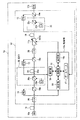
【図1】本発明が適用される光伝送システムの動作原理を説明するための図である。
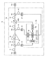
【図2】本発明の第1実施形態に係る光波長多重伝送装置の構成例を示す図である。
【図3】(a)は光フィルタの模式的な外観図であり、(b)はファイバグレーティングの模式的な外観図である。
【図4】(a)はファイバグレーティングの個々の損失波長特性を示す図であり、(b)はファイバグレーティングのトータルの損失波長特性を示す図である。
【図5】本発明の第1実施形態に係る制御部のブロック図である。
【図6】(a)は伝送路の損失波長特性データの一例を示す図であり、(b)はゲインブロックの利得波長特性データの一例を示す図であり、(c)は損失波長特性データと利得波長特性データとを加算した後の損失波長特性データの一例を示す図であり、(d)は逆特性データの一例を示す図である。
【図7】本発明の第1実施形態に係る通過逆特性の演算例を説明するための図である。
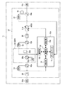
【図8】本発明の第2実施形態に係る光波長多重伝送装置の構成例を示す図である。
【図9】本発明の第3実施形態に係る光伝送システムの概略的な構成図である。
【図10】本発明の第3実施形態に係る通過波長特性制御を説明するためのフローチャートである。
【図11】冗長システムを説明するための図である。
【図12】本発明の第4実施形態に係る光伝送システムの概略的な構成図である。
【図13】本発明の第4実施形態に係る通過波長特性制御を説明するためのフローチャートである。
【図14】本発明の第5実施形態に係る光伝送システムの動作原理を説明するための図である。
【図15】本発明の第5実施形態に係る光伝送システムの概略的な構成図である。
【図16】本発明の第6実施形態に係る光伝送システムの動作原理を説明するための図である。
【図17】本発明の第6実施形態に係る光伝送システムの概略的な構成図である。
【図18】本発明の第7実施形態に係る光伝送システムの動作原理を説明するための図である。
【図19】本発明の第7実施形態に係る光伝送システムの概略的な構成図である。
【図20】本発明の第8実施形態に係る光伝送システムの概略的な構成図である。
【図21】本発明の第8実施形態に係る通過波長特性制御を説明するためのフローチャートである。
【図22】本発明の第9実施形態に係る光伝送システムの動作原理を説明するための図である。
【図23】本発明の第9実施形態に係る光伝送システムの概略的な構成図である。
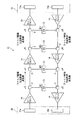
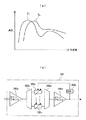
【図24】(a)は利得プロファイルの形状を示す図であり、(b)は光スペクトラムアナライザを用いた光パワーモニタの一例を示す図である。
【符号の説明】
1,1a〜1f,41a,41b 光伝送システム
2,2a〜2i 光増幅器
10a,10b 光カプラ
11 光フィルタ(可変利得アナライザ)
12,12a〜12c 制御部
13 フォトダイオード(光パワーモニタ,取得部)
14,26 ゲインブロック(増幅媒体)
15a,15b コアネットワーク
16 演算部
16a 設定部
17 データベース
18,18a 伝送路
18b 現用伝送路
18c 予備用伝送路
19 測定部
20 光アイソレータ
25 EDFA
25a EDF(集中増幅型伝送路)
25b 励起レーザ
25c 光カプラ
27 光スペクトラムアナライザ
30,31 光波長多重端局
30a,31b 送信器
30b,31a 受信器
32 合分波器(取得部)
33 NMS(ネットワークマネージメントシステム)
34a〜34c 装置監視系(装置監視システム)
97a フィルタ制御ドライバ回路部
97b バス
97c CPU
97d ブートROM
97e 不揮発性メモリ
97f RAM
97g 入出力インターフェース
98 チップ
99 ファイバグレーティング[0001]
TECHNICAL FIELD OF THE INVENTION
The present invention relates to an optical amplifier, a method of controlling a transmission wavelength characteristic in an optical amplifier, and an optical transmission system suitable for use in controlling the transmission wavelength characteristic of amplified wavelength-division multiplexed light, for example.
[0002]
[Prior art]
2. Description of the Related Art In recent years, with the rapid increase in the number of Internet users and the start of distribution services for images and the like, constant access to a backbone high-speed optical network serving as the Internet backbone has been demanded. A WDM (Wavelength Division Multiplexing) system for multiplexing and transmitting a plurality of optical signals having different wavelengths on a single optical fiber cable (hereinafter, referred to as a fiber unless otherwise specified) is based on: Since the transmission capacity can be increased in proportion to the number of wavelengths, its practical use is desired.
[0003]
An optical network to which a large number of fibers are connected is provided with a wavelength division multiplexing optical amplifying device (hereinafter abbreviated as device) for performing high-speed, large-capacity, and long-distance data transmission, and has an optical amplifier. The optical amplifier compensates for the loss of the optical signal, so that the optical signal is relayed. The cause of the loss is mainly due to scattering of the optical signal to the outside of the fiber or absorption by impurities inside the fiber.
[0004]
As one example of the optical amplifier, an erbium-doped optical fiber amplifier (EDFA) is well known. This EDFA is an optical amplifier composed of a fiber itself into which a rare earth ion such as erbium (Er) is implanted. This amplifying function is such that pumping light (pumping light) is input to the EDF, and the input pumping light converts Er. Excitation is performed, and the excitation energy amplifies an optical signal passing through the EDF.
[0005]
Conventional optical amplifiers are classified into the following two types (J1) and (J2) in order to eliminate both deviations of gain (gain) and loss (loss) for each wavelength and compensate optical signals. I was
(J1) Compensation of gain profile (undulation) of EDF
(J2) Compensation of first-order tilt by transmission path loss and stimulated Raman scattering (SRS)
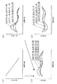
The gain profile of (J1) means gain wavelength characteristics (wavelength dependence of gain). The shape of the gain profile is, for example, a shape as shown in FIG. 1 / Δ 0 ) Is determined by (δ 1 / Δ 0 Represents the upper level ion density and the total ion density, respectively. ). Here, in order to make the gain wavelength characteristic flat, it is necessary to make the number of holes for radiation constant regardless of the input light power. The operation state of the optical amplifier at this time corresponds to an automatic gain control (Automatic Gain Control) state that does not depend on the input optical power. However, in this AGC state, excitation may be unnecessary (wasted).
[0006]
For example, when the output light power is 0 [dBm] and the pumping ratio remains at 20 [dB], the input light having the input light power of -10 [dBm] becomes 10 [dBm] after amplification. Value. Therefore, in order to flatten the output wavelength characteristics, the power of 10 [dBm] obtained by amplification using an attenuator needs to be attenuated. In this case, a network administrator (automatic level control) executes an automatic level control (automatic level control), and an external optical filter is provided on the output side of the EDFA. Thus, the shape of the gain profile is flattened. The method using the external optical filter consumes the least power. The optical filter will be described later.
[0007]
Furthermore, the gain profile accumulates as the number of relay stages increases and affects the quality of the optical signal. For this reason, when the EDF is used as the transmission path, the optical amplifier compensates for the optical signal using a fixed filter (a filter whose band is fixed) having an inverse characteristic to the gain profile of the EDF.
Next, the SRS of (J2) is a nonlinear phenomenon of the transmission fiber that shifts the optical power on the high frequency side to the low frequency side. This SRS is a phenomenon in which, when a high-power monochromatic light is applied to an optical fiber, coherent Stokes light whose wavelength is shifted by a specific amount due to interaction with the optical phonon of the optical fiber is generated by stimulated emission. Is applied to set the wavelength of monochromatic light so that the Stokes light has the same wavelength as the signal light, and amplify the signal light by stimulated emission. The SRS compensates for the first-order slope of the gain profile. Since the SRS is generated in the fiber having the dielectric, the administrator adjusts the output of the pump light and the like according to the type of the transmission path.
[0008]
Raman amplification is amplification using the stimulated Raman scattering effect, and a desired gain wavelength characteristic can be obtained by adjusting the pump light power and the oscillation wavelength.
Conventionally, an optical transmission system connects an EDF and an optical filter in multiple stages, controls the excitation of the excitation light of the input light for the EDF, and uses a fixed filter having a fixed band characteristic to transmit the EDF and out-of-band. Noise light was suppressed.
[0009]
As a result, the optical transmission system can use parts in use as it is, and realizes reliability and low cost. Further, the optical transmission system compensates for low-noise tilt (a parameter representing the first-order slope of the gain of the relay amplifier) by using the Raman amplifier together. Each counter station monitored the primary slope of the gain because the output level after the relay amplification was not uniform with respect to wavelength. Unless otherwise specified, the opposing station is used as including both a relay station (repeater, repeater station or repeater node) and an optical wavelength multiplexing terminal station (terminal station).
[0010]
Further, a method using an optical filter has been proposed. The optical filter is a variable gain equalizer (VGEQ: Variable Gain Equalizer) that can variably adjust (tunable) the gain or loss amount for each wavelength. This optical filter uses, as an optical amplifier, a passive component that consumes small power and that can adjust gain and loss. This function is realized by, for example, a variable filter (trade name: Active Gain Equalizer) or the like. . In the method using the optical filter, the optical amplifier controls the characteristics of the variable filter by monitoring the output optical power of a desired optical wavelength using an optical spectrum analyzer (OSA) or the like. (For example, see Patent Document 1).
[0011]
In the optical multiplexing method described in Patent Document 1, a signal light wavelength-multiplexed in an optical multiplexing board is transmitted through a tunable filter, the level is measured for each wavelength by a photodiode, and a setting unit is set based on the level value. The movable light attenuator is adjusted to adjust each level to a constant value. As a result, the level of the wavelength multiplexed signal light can always be automatically adjusted.
[0012]
FIG. 24B is a diagram illustrating an example of an optical power monitor using an optical spectrum analyzer. In the
[0013]
The method using the
Conventionally, the optical transmission system has realized the wavelength flatness of the relay amplification and the amplification output by the combination of the EDFA and the Raman amplifier, and the compensation of the optical signal is performed by the optical filter alone or by the optical filter. It has been implemented by a combination of a filter and an SRS.
[0014]
[Patent Document 1]
JP-A-10-276173
[0015]
[Problems to be solved by the invention]
By the way, in the case where the optical filter and the SRS are combined, when the SRS is used as the subsequent amplifier, the characteristics of the EDFA in the former stage have an unfavorable influence on the SRS in the latter stage. Specifically, when the gain profile shape of the EDFA changes according to the secondary (higher order) operating point, the administrator cannot set the gain obtained by the subsequent SRS to active or tunable according to the wavelength. The reason is that the gain profile of the SRS is determined by the type of the transmission path. Therefore, the optical amplifier cannot compensate for only the lost band when the SRS is used as a subsequent-stage amplifier.
[0016]
For this reason, the administrator adjusts the pumping light output of the EDFA provided in the preceding stage so as not to change the secondary operating point, and performs relay amplification using Raman amplification as needed. Specifically, each relay amplifier controls the filter characteristics to an optimal state using the optical wavelength monitor.
However, when using an optical wavelength monitor, the optical transmission system needs to transmit monitor light of a specific wavelength in all amplification bands of the optical amplifier. In addition, the monitor light is unnecessary since it is used only for monitoring the gain wavelength characteristic of the optical amplifier. In addition, the administrator must force customers to purchase redundant equipment such as an optical spectrum analyzer for monitoring. Therefore, the initial introduction cost imposed on the customer increases.
[0017]
In a filter control method using an optical spectrum analyzer or the like, an optical amplifier feedback-controls a monitoring result to an upstream side of a transmission line. This feedback control is accurate, but is susceptible to external disturbances when increasing or decreasing the wavelength channel (channel assigned to the optical wavelength). In addition, this filter control method requires a considerable amount of time for control to stabilize. In general, if a network needs to be relocated when a network is connected in a mesh, a failure recovery operation is indispensable, and the relocation of the failure also requires a considerable amount of time. Therefore, there is a problem that the gain adjustment using the optical wavelength monitor is difficult in terms of time and cannot be controlled practically.
[0018]
Furthermore, so-called optical amplifiers such as EDFAs and Raman amplifiers do not operate efficiently, and there are many redundant parts in terms of both power consumption and equipment cost. Pump lasers for EDFAs and SRSs consume large amounts of power. Therefore, each device needs to be provided with a heat countermeasure for releasing generated heat with a large power, and the heat countermeasure increases the scale of the device and the cost. In particular, the size of the Raman amplifier is large, resulting in high costs.
[0019]
The present invention has been made in view of such problems, and in an optical wavelength-division multiplexing optical transmission system using an optical filter, enables more rapid optical filter control and more efficient optical amplification, Optical amplifiers and optical amplifiers that do not change the already assigned optical wavelengths during network expansion, are resistant to external disturbances when increasing or decreasing the optical wavelengths, and can suppress the initial introduction cost by a simple configuration. It is an object to provide a wavelength characteristic control method and an optical transmission system.
[0020]
[Means for Solving the Problems]
For this reason, the optical amplifier of the present invention comprises an amplification medium for amplifying the wavelength multiplexed light, and the input light power of the wavelength multiplexed light on the input side of the amplification medium and the output light power of the wavelength multiplexed light on the output side of the amplification medium. A measuring unit for measuring at least one optical power, a variable gain equalizer connected to the transmission path and capable of variably setting a passing wavelength characteristic, and a database holding at least data indicating the wavelength characteristic for each type of the transmission path. Based on the obtained transmission path type, the optical power measured by the measurement unit, and the data held in the database, a calculation unit that calculates the pass inverse characteristic caused by the wavelength characteristic of the variable gain equalizer, And a setting unit for setting the passing wavelength characteristic of the variable gain equalizer based on the passing inverse characteristic calculated by the calculating unit. Section 1).
[0021]
This database can be applied to two types of transmission lines: a centralized amplification type transmission line and a transmission line amplification type transmission line.
In other words, the database holds the wavelength characteristics corresponding to the input optical power and the output optical power of the centralized amplification type transmission line, respectively, and the arithmetic unit stores the wavelength characteristics corresponding to the input optical power and the output optical power stored in the database. It may be configured to calculate the reverse pass characteristic based on the corresponding wavelength characteristic (claim 2).
[0022]
Further, the database holds a wavelength characteristic corresponding to the pumping light power of the transmission line amplification type transmission line, and the calculating unit calculates the difference between the pumping light power stored in the database and the output light power measured by the measuring unit. It may be configured to calculate the pass inverse characteristic based on the wavelength characteristic corresponding to each (claim 3).
Further, in the transmission wavelength characteristic control method in the optical amplifier according to the present invention, the measuring unit connected to the amplification medium for amplifying the wavelength multiplexed light may be configured such that the input optical power of the wavelength multiplexed light at the input side of the amplification medium and the output side of the amplification medium are Measuring an optical power of at least one of the output optical powers of the wavelength-multiplexed light in the above, an obtaining unit connected to the measuring unit obtains a type of the transmission line, and a calculating unit connected to the measuring unit is Based on the measured optical power, the acquired transmission path type, and at least the data indicating the wavelength characteristic for each transmission path type stored in the database, the transmission wavelength characteristic connected to the transmission path. Calculates the reverse pass characteristic of a variable gain equalizer that can variably set the transmission wavelength, and the setting unit connected to the calculation unit sets the pass wavelength characteristic of the variable gain equalizer based on the reverse pass characteristic calculated by the calculation unit It is characterized in Rukoto (claim 4).
[0023]
An optical transmission system according to the present invention is an optical transmission system including a transmission path for transmitting an optical signal and an optical amplifier for amplifying wavelength-division multiplexed light transmitted on the transmission path. Amplifying medium for amplifying the optical signal, a measuring unit for measuring at least one of the input optical power of the wavelength multiplexed light on the input side of the amplifying medium and the output optical power of the wavelength multiplexed light on the output side of the amplifying medium, and a transmission unit. A variable gain equalizer connected to the transmission path and capable of variably setting the passing wavelength characteristic, a database holding at least data indicating the wavelength characteristic for each type of the transmission path, the acquired transmission path type, and a measuring unit. A computing unit that computes a pass inverse characteristic caused by the wavelength characteristic of the variable gain equalizer based on the measured optical power and the data held in the database; Is characterized in that it is configured to include a setting section that sets a pass wavelength characteristic of the variable gain equalizers based on the inverse characteristic passage which is (claim 5).
[0024]
BEST MODE FOR CARRYING OUT THE INVENTION
Hereinafter, embodiments of the present invention will be described with reference to the drawings.
(A) Description of the first embodiment of the present invention
FIG. 1 is a diagram for explaining the operation principle of an optical transmission system to which the present invention is applied. The optical transmission system 1 shown in FIG. 1 is a system for transmitting wavelength-division multiplexed light, and includes core networks (CN: Core Networks) 15a and 15b, a transmission line (fiber) 18, and an
[0025]
Here, each of the
Hereinafter, the transmission direction of the optical signal is a direction from the
[0026]
The
Here, the
[0027]
The
[0028]
The
The
[0029]
After the activation of the
[0030]
Further, the amount of tilt of the
[0031]
Next, the
Here, the measuring
[0032]
The
[0033]
Specifically, when the
[0034]
Further, the gain wavelength characteristic is determined by the value per unit distance of each loss wavelength characteristic of the single mode fiber and the non-zero dispersion shift fiber, and the respective values of the input optical power and the output optical power of the EDFA by the erbium-doped fiber. . Here, a single-mode fiber means that only a single-mode optical signal can be transmitted and a mode dispersion (a narrowing of a transmission band caused by a difference in each speed caused when a plurality of modes of an optical signal is transmitted). )) And no broadband. On the other hand, the non-zero dispersion shift fiber is for avoiding a non-linear phenomenon, and the zero dispersion wavelength band and the transmission wavelength band of the fiber are separated.
[0035]
The function of the
[0036]
As described above, the EDFA retains the gain wavelength characteristic using the input / output optical power of the
Further, the
[0037]
Next, the operation unit 16 (see FIG. 1) performs an
In order to obtain the reverse transmission characteristic, the
[0038]
That is, the wavelength characteristics (gain wavelength characteristics and loss wavelength characteristics) are both the input light power (total power) of the EDFA, the gain (total power) of the EDFA, the type of the
[0039]
The setting
Accordingly, in the transmission wavelength characteristic control method in the optical amplifier according to the present invention, the measuring
[0040]
Further, the
[0041]
As described above, in the case of the initial introduction, when the optical transmission system 1 is operated in a state where the number of multiplexed wavelengths is small, the
As a result, even after the
[0042]
Next, a method of controlling the transmission wavelength characteristic when the
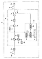
FIG. 2 is a diagram illustrating a configuration example of the optical wavelength division multiplexing transmission apparatus according to the first embodiment of the present invention. The
[0043]
Here, the
[0044]
The
[0045]
Next, the
[0046]
On the other hand, FIG. 3B is a schematic external view of the fiber grating 99, and when the
FIG. 4A is a diagram showing the individual loss wavelength characteristics of the fiber grating 99, and the cutoff amounts of the
[0047]
Thus, the loss of the fiber grating 99 can be adjusted by the temperature. Note that the characteristics of the
The
[0048]
FIG. 5 is a block diagram of the
[0049]
The characteristic data stored in the
FIGS. 6A to 6D are diagrams illustrating an example of the wavelength characteristic data according to the first embodiment of the present invention, and FIG. 7 is a diagram illustrating the calculation of the pass inverse characteristic according to the first embodiment of the present invention. It is a figure for explaining an example. The
[0050]
Further, the characteristic data shown in FIG. 6C shows the loss wavelength characteristic data after adding the loss wavelength characteristic data and the gain wavelength characteristic data shown in FIGS. 6A and 6B.
Then, the
[0051]
FIG. 7 is a diagram for explaining the interpolation according to the first embodiment of the present invention. A curve 1 shown in FIG. 7 is a gain wavelength characteristic at the time of the input light power A1 and the output light power B1, and a
[0052]
Further, in calculating the control value of the
[0053]
Specifically, when the calculated wavelength characteristic data value is Gi (dB), the control target value Li of the
[0054]
This calculation method is also used in other embodiments and modified examples described below, unless otherwise specified.
When calculating the wavelength characteristics as a whole with such a configuration, the
[0055]
The timing of setting the inverse characteristic data in the
Before the
[0056]
On the other hand, after starting the
Therefore, the setting of the
[0057]
As described above, the
Therefore, the size and cost of the device can be reduced, and for example, the price of the
[0058]
In this way, since the control target value at the time of starting the
In this manner, the
[0059]
(B) Description of the second embodiment of the present invention
In the second embodiment, a case where the gain block 14 (see FIG. 1) is configured by a Raman amplifier will be described.
FIG. 8 is a diagram illustrating a configuration example of an optical wavelength multiplex transmission apparatus according to a second embodiment of the present invention. The
[0060]
Here, the measuring
[0061]
Further, the
[0062]
The gain wavelength characteristic is determined by the value per unit distance of the loss wavelength characteristic of the single mode fiber and the non-zero dispersion shifted fiber, and the pump light power for Raman amplification. That is, the
[0063]
On the other hand, the
Further, the
[0064]
With such a configuration, the
[0065]
Then, the
[0066]
As described above, the optical amplifier 2b can smooth the wavelength characteristic of the output light without using additional components such as an optical spectrum analyzer and can suppress the output of redundant pump light power. Further, the dummy light becomes unnecessary, and the cost of the optical amplifier 2b and the
[0067]
In this way, when adding or removing the
(C) Description of the third embodiment of the present invention
The third embodiment is a modification of the first embodiment and the second embodiment. In the
[0068]
FIG. 9 is a schematic configuration diagram of an optical transmission system according to the third embodiment of the present invention. The
[0069]
Then, each relay station connected to the
[0070]
Each of the
[0071]
As a result, the
[0072]
Further, the
Each of the
[0073]
Further, each relay station connected to the
As described above, since the data acquisition direction required for calculating the loss wavelength characteristic of the
[0074]
The
With such a configuration, transmission wavelength characteristic control in the
FIG. 10 is a flowchart for explaining the passing wavelength characteristic control according to the third embodiment of the present invention. The
[0075]
As described above, also in the third embodiment, the same effects as those obtained in the first embodiment and the second embodiment can be obtained.
Further, the transmission wavelength characteristic control in the
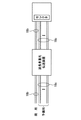
[0076]
With this configuration, when a failure such as disconnection occurs in the working
[0077]
As a result, the output light characteristics from the relay station are smoothed, and in the event of a trouble transfer or the like, the
(D) Description of a fourth embodiment of the present invention
In the optical transmission system according to the fourth embodiment, a network management system (NMS) connected to each station is provided, and this NMS is a
[0078]
FIG. 12 is a schematic configuration diagram of an optical transmission system according to the fourth embodiment of the present invention. The
[0079]
The
Further, the
[0080]
As a result, the type and the transmission path length of the
The calculating
[0081]
With such a configuration, the
FIG. 13 is a flowchart for explaining the passing wavelength characteristic control according to the fourth embodiment of the present invention. When the type of the
[0082]
Thus, the upstream station considers the loss wavelength characteristic after transmission in advance, adds a different weight to the wavelength characteristic data of the loss for each wavelength, and transmits the wavelength characteristic data of the loss to the downstream station.
A conventional downstream station operates to improve the SN ratio (Signal Noise Ratio) for the most deteriorated wavelength among the wavelengths (channels) included in the transmission light. On the other hand, the present downstream station does not improve the most deteriorated wavelength, improves the S / N ratio, and provides better transmission than amplifying an optical signal whose reception level is not managed in the downstream station. Properties can be obtained.
[0083]
In the fourth embodiment, the
Furthermore, the present invention can be implemented using the following three types of modifications, and these modifications can be made by applying any of EDFA and Raman amplification.
[0084]
As a first modified example, each relay station controls so as to compensate for the loss wavelength characteristic of the
As a second modification, each relay station controls the loss wavelength characteristic of the
[0085]
As a third modified example, each relay station can set the type and length of the
(E) Description of a fifth embodiment of the present invention
In the fifth embodiment, the
[0086]
FIG. 14 is a diagram for explaining the operation principle of the optical transmission system according to the fifth embodiment of the present invention. The optical transmission system 1f shown in FIG. 14 includes an optical amplifier 2c for amplifying the wavelength-division multiplexed light transmitted through the
[0087]
The
Then, the
[0088]
With such a configuration, the
[0089]
Thereby, the passband characteristics are optimized. Also, an appropriate passband characteristic can be set before and after the activation of the
Further, a plurality of
[0090]
Next, a method of controlling the transmission wavelength characteristic when the
FIG. 15 is a schematic configuration diagram of an optical transmission system according to a fifth embodiment of the present invention, which is an example of an embodiment of the
[0091]
Thereby, in the
[0092]
Thus, even when the gain blocks 26 are connected in a plurality of stages, the characteristic data can be stabilized.
(F) Description of the sixth embodiment of the present invention
As a modification of the above-described first embodiment, an optical spectrum analyzer can be used together, and the loss wavelength characteristic (or gain wavelength characteristic) set by the
[0093]
FIG. 16 is a diagram for explaining the operation principle of the optical transmission system according to the sixth embodiment of the present invention. In the
[0094]
With such a configuration, after the
[0095]
As a result, the inverse characteristic set for the
FIG. 17 is a schematic configuration diagram of an optical transmission system according to the sixth embodiment of the present invention. The
[0096]
Thus, in the optical transmission system 1i, the output light from the
[0097]
As described above, a slight deviation of the value is monitored and the deviation is corrected, so that the control accuracy is improved.
(G) Description of the seventh embodiment of the present invention
In the seventh embodiment, a case where the number of connected optical amplifiers is plural will be described. FIG. 18 is a diagram for explaining the operation principle of the optical transmission system according to the seventh embodiment of the present invention. The optical transmission system 1i shown in FIG. 18 includes an
[0098]
The
FIG. 19 is a schematic configuration diagram of an optical transmission system according to the seventh embodiment of the present invention, in which the
[0099]
The
[0100]
With such a configuration, the optical signal input to the
[0101]
As described above, since each of the plurality of gain blocks 14 is constituted by an EDFA, a plurality of
As a first modified example, the
[0102]
As a second modified example, the
(H) Description of Eighth Embodiment of the Present Invention
In order to more precisely compensate for the characteristics of the
[0103]
FIG. 20 is a schematic configuration diagram of the optical transmission system according to the eighth embodiment of the present invention. The transmission direction of the optical signal shown in FIG. 20 is the first direction (from the
[0104]
The
Next, a method of calculating the pass inverse characteristic of the
The calculation targets of the calculation unit 16 (not shown) are the WDL of the input fiber, the amount of SRS generated, and the WDG of the EDFA. That is, the
[0105]
Specifically, the
[0106]
In other words, the
[0107]
Next, three modes will be described as examples of the control method of the loss wavelength characteristic.
First, in controlling the characteristics of the
[0108]
Secondly, in the same configuration as the first configuration, the
[0109]
Third, the
[0110]
With such a configuration, the control of the wavelength characteristic in the eighth embodiment is performed.
FIG. 21 is a flowchart for explaining the transmission wavelength characteristic control according to the eighth embodiment of the present invention. When the
[0111]
Further, the
Then, the
[0112]
As described above, by using the present configuration and control, the
In this way, the transmission characteristics for each wavelength can be made uniform and improved. In addition, in this way, even when an optical component that deteriorates over time is provided, a shift due to the degradation can be efficiently absorbed.
[0113]
(I) Description of the ninth embodiment of the present invention
In the ninth embodiment, a description will be given of a method of performing more precise control in order to adjust a loss wavelength characteristic of a gain block using a Raman amplifier in a gain block.
FIG. 22 is a diagram for explaining the operation principle of the optical transmission system according to the ninth embodiment of the present invention. The
[0114]
Further, the
[0115]
In addition, for example, the WDL due to the
[0116]
FIG. 23 is a schematic configuration diagram of an optical transmission system according to a ninth embodiment of the present invention. The
With such a configuration, in the
[0117]
As described above, the use of the present embodiment enables desired compensation.
As described above, in the
(J) Other
The present invention is not limited to the above-described embodiment and its modifications, and can be implemented with various modifications without departing from the spirit of the present invention.
[0118]
Both the loss wavelength characteristic and the gain wavelength characteristic can be expressed as a gain wavelength characteristic and a use wavelength characteristic.
(K) Note
(Supplementary Note 1) An amplification medium for amplifying the wavelength division multiplexed light,
A measurement unit that measures at least one of the input optical power of the wavelength multiplexed light on the input side of the amplification medium and the output optical power of the wavelength multiplexed light on the output side of the amplification medium;
A variable gain equalizer connected to the transmission path and capable of variably setting the passing wavelength characteristic,
A database holding at least data indicating wavelength characteristics for each type of transmission path,
Based on the acquired type of the transmission path, the optical power measured by the measurement unit, and the data held in the database, a pass inverse characteristic caused by the wavelength characteristic of the variable gain equalizer is calculated. An operation unit that performs
An optical amplifier comprising: a setting unit that sets a passing wavelength characteristic of the variable gain equalizer based on the passing inverse characteristic calculated by the calculating unit.
[0119]
(Supplementary Note 2) An amplification medium for amplifying the wavelength multiplexed light,
A measuring unit that measures at least one optical power of the input optical power of the wavelength multiplexed light on the input side of the amplification medium and the output optical power of the wavelength multiplexed light on the output side of the amplification medium;
A variable gain equalizer connected to the transmission path and capable of variably setting the passing wavelength characteristic,
A database holding at least data indicating wavelength characteristics for each type of transmission path,
An acquisition unit that acquires the type of the transmission path;
Based on the type of the transmission path obtained by the obtaining unit, the optical power measured by the measuring unit, and the data held in the database, the wavelength characteristic of the variable gain equalizer is caused. A calculation unit for calculating a reverse pass characteristic;
An optical amplifier comprising: a setting unit that sets a passing wavelength characteristic of the variable gain equalizer based on the passing inverse characteristic calculated by the calculating unit.
[0120]
(Supplementary note 3) The optical amplifier according to
(Supplementary Note 4) The database further includes:
4. The optical amplifier according to any one of Supplementary Notes 1 to 3, wherein information on a length of a transmission path connected to the amplification medium is held.
[0121]
(Supplementary Note 5) The database holds wavelength characteristics respectively corresponding to the input optical power and the output optical power of the centralized amplification type transmission line,
The supplementary note, wherein the computing unit is configured to compute the passing inverse characteristic based on the wavelength characteristics respectively corresponding to the input optical power and the output optical power held in the database. The optical amplifier according to any one of claims 1 to 3.
[0122]
(Supplementary Note 6) The arithmetic unit includes:
6. The optical amplifier according to claim 5, wherein the optical amplifier is configured to calculate the reverse pass characteristic so as to control the gain of the centralized amplification type transmission line constant.
(Supplementary Note 7)
5. The optical amplifier according to
[0123]
(Supplementary Note 8) The acquisition unit:
At least one of the type of the transmission line connected to the amplification medium and the information on the transmission line length is changed to any one of a monitoring light from the upstream side of the transmission line and a device monitoring system for monitoring a transmission state. 4. The optical amplifier according to
[0124]
(Supplementary Note 9) The database holds wavelength characteristics corresponding to the pumping light power of the transmission line amplification type transmission line,
The calculation unit is configured to calculate the pass inverse characteristic based on the wavelength characteristics corresponding to the excitation light power held in the database and the output light power measured by the measurement unit. 4. The optical amplifier according to any one of supplementary notes 1 to 3, characterized in that:
[0125]
(Supplementary Note 10) The arithmetic unit includes data indicating wavelength characteristics for each type of the transmission path provided in the first direction included in the received light from the first direction, and a second direction. Based on the wavelength multiplexing number data included in the received light from the side, and calculate the reverse pass characteristics,
4. The optical amplifier according to any one of supplementary notes 1 to 3, wherein the setting unit is configured to set a transmission wavelength characteristic of a portion on the first direction side of the transmission path.
[0126]
(Supplementary Note 11) The amplification medium amplifies using the centralized amplification type transmission line, and the setting unit adjusts the input optical power and the output optical power of the centralized amplification type transmission line after starting the variable gain equalizer. 4. The optical amplifier according to any one of Supplementary Notes 1 to 3, wherein the optical amplifier is configured to set the passing wavelength characteristic based on the setting.
(Supplementary Note 12) The amplification medium amplifies using a transmission line capable of Raman amplification,
Wherein the setting unit is configured to set the transmission wavelength characteristic based on the pumping light power of the Raman amplifiable transmission line after the activation of the variable gain equalizer. 3. The optical amplifier according to any one of 3.
[0127]
(Supplementary Note 13) The calculation unit calculates the passing inverse characteristic on the first direction side based on data included in the received light,
The optical device according to claim 10, wherein the setting unit is configured to set a reverse pass characteristic of a first direction side portion of the transmission path based on the data held in the database. amplifier.
[0128]
(Supplementary Note 14) The computing unit computes the passing inverse characteristic on the first direction side based on data from the own station,
The configuration according to claim 10, wherein the setting unit is configured to set a passing reverse characteristic for a first direction side portion of the transmission path based on the second data held in the database. Optical amplifier.
[0129]
(Supplementary Note 15) The measuring unit connected to the amplification medium for amplifying the wavelength multiplexed light includes an input light power of the wavelength multiplexed light at an input side of the amplification medium and an output light of the wavelength multiplexed light at an output side of the amplification medium. Measuring at least one of the optical powers,
An acquisition unit connected to the measurement unit acquires the type of the transmission path,
An arithmetic unit connected to the measuring unit is configured to calculate the optical power measured by the measuring unit, the acquired type of the transmission line, and the wavelength characteristics of at least each type of the transmission line stored in a database. Based on the data indicating, the pass inverse characteristic of the variable gain equalizer connected to the transmission path and capable of variably setting the pass wavelength characteristic is calculated,
A setting unit connected to the operation unit, which sets a transmission wavelength characteristic of the variable gain equalizer based on the pass inverse characteristic calculated by the operation unit, a transmission wavelength characteristic control method in an optical amplifier. .
[0130]
(Supplementary Note 16) An optical transmission system including a transmission path for transmitting an optical signal and an optical amplifier for amplifying wavelength-division multiplexed light transmitted on the transmission path,
The optical amplifier is
An amplification medium for amplifying the wavelength multiplexed light;
A measurement unit that measures at least one of the input optical power of the wavelength multiplexed light on the input side of the amplification medium and the output optical power of the wavelength multiplexed light on the output side of the amplification medium;
A variable gain equalizer connected to the transmission path and capable of variably setting the passing wavelength characteristic,
A database holding at least data indicating wavelength characteristics for each type of transmission path,
Based on the acquired type of the transmission path, the optical power measured by the measurement unit, and the data held in the database, a pass inverse characteristic caused by the wavelength characteristic of the variable gain equalizer is calculated. An operation unit that performs
An optical transmission system comprising: a setting unit that sets a passing wavelength characteristic of the variable gain equalizer based on the passing inverse characteristic calculated by the calculating unit.
[0131]
【The invention's effect】
As described above in detail, according to the optical amplifier of the present invention (claims 1 to 3), the transmission wavelength characteristic control method in the optical amplifier (claim 4), and the optical transmission system (claim 5), the following will be described. Effects or benefits.
(1) According to the optical amplifier of the present invention, the amplification medium for amplifying the wavelength multiplexed light, and the input light power of the wavelength multiplexed light on the input side of the amplification medium and the output light power of the wavelength multiplexed light on the output side of the amplification medium. A measuring unit that measures at least one of the optical powers, a variable gain equalizer connected to the transmission path and capable of variably setting the passing wavelength characteristic, and holding at least data indicating the wavelength characteristic for each type of the transmission path. Calculation for calculating a pass inverse characteristic caused by the wavelength characteristic of the variable gain equalizer based on the database, the acquired transmission path type, the optical power measured by the measurement unit, and the data held in the database. And a setting unit for setting the pass wavelength characteristic of the variable gain equalizer based on the pass inverse characteristic calculated by the calculation unit. The device can smooth the loss wavelength characteristic or the gain wavelength characteristic without using an additional component such as an optical spectrum analyzer, and can reduce the size and cost of the device and eliminate the need for dummy light. The system price can be reduced (claim 1).
[0132]
(2) According to the optical amplifier of the present invention, the amplifying medium, the measuring unit, the variable gain equalizer, the database, the acquiring unit for acquiring the type of the transmission line, and the type of the transmission line acquired by the acquiring unit , An operation unit, and a setting unit, so that the control target value at the time of starting the optical amplifier can be appropriately set, and the time until signal communication at the time of starting the optical transmission system can be set. And prevent adverse effects on optical signals having optical wavelengths other than the optical wavelengths subject to expansion / reduction due to disturbances to the control system during expansion / reduction. Can be stabilized.
[0133]
(3) The measuring section may be configured to measure the pump light power at the input side of the amplification medium. In this case, the measured light power and the wavelength characteristic data held in the database are converted. Based on this, appropriate passband characteristics of the variable gain equalizer can be obtained as appropriate.
(4) The database may further be configured to hold information on the length of the transmission path connected to the amplification medium. In this case, the loss wavelength characteristic can be predicted in advance, and different weights are assigned for each wavelength. Can be compensated.
[0134]
(5) The database holds the wavelength characteristics corresponding to the input optical power and the output optical power of the centralized amplification type transmission line, respectively, and the calculation unit calculates the input optical power and the output optical power stored in the database. The configuration may be such that the pass inverse characteristic is calculated based on the wavelength characteristic corresponding to each. In this case, the control target value at the time of starting the variable gain equalizer can be appropriately set, so that the optical transmission system Can be shortened, for example, between the time when is started and the time when signal communication between relay stations is started (claim 2).
[0135]
(6) The calculation unit may be configured to calculate the reverse pass characteristic so as to control the gain of the centralized amplification type transmission path to a constant value. In this case, when the optical transmission system is expanded or reduced. The operation of the control system is stabilized.
(7) The calculation unit may be configured to calculate the pass inverse characteristic based on the data in which the wavelength multiplex number data and the wavelength characteristic due to the stimulated Raman scattering effect are associated with each other. The calculation of the inverse pass characteristic of the gain equalizer is simplified.
[0136]
(8) The acquisition unit determines at least one of the type of the transmission path connected to the amplification medium and the information on the transmission path length by a monitoring light from the upstream side of the transmission path and an apparatus monitoring system that monitors the transmission status. The information may be obtained from any one of them, and in this case, the updated information is efficiently used.
(9) The database holds the wavelength characteristic corresponding to the pumping light power of the transmission line amplification type transmission line, and the arithmetic unit calculates the pumping light power stored in the database and the output light power measured by the measuring unit. May be calculated based on the wavelength characteristic corresponding to each of the above. In this case, the loss wavelength characteristic can be easily obtained regardless of the type of the transmission path. Further, the variable gain equalizer is controlled both at the time of starting and after the starting (claim 3).
[0137]
(10) The arithmetic unit includes data indicating the wavelength characteristic for each type of the transmission path provided in the first direction included in the received light from the first direction, and data from the second direction. The setting unit may be configured to calculate the reverse pass characteristic based on the wavelength multiplex number data included in the received light, and to set the pass wavelength characteristic of a portion on the first direction side of the transmission path. By doing so, the calculation of the inverse pass characteristic of the variable gain equalizer is simplified.
[0138]
(11) The amplifying medium amplifies using the centralized amplification type transmission line, and the setting unit, after activation of the variable gain equalizer, determines the transmission wavelength characteristic based on the input optical power and the output optical power of the centralized amplification type transmission line. May be configured so that the wavelength characteristics can be appropriately controlled before and after the activation of the optical amplifier.
(12) The amplification medium amplifies using the transmission line capable of Raman amplification, and the setting unit sets the transmission wavelength characteristic based on the excitation light power of the transmission line capable of Raman amplification after the activation of the variable gain equalizer. In this case, quick wavelength characteristic control and efficient optical amplification can be performed. For example, when expanding a network, the network can be expanded without changing the band of optical wavelengths already assigned to a customer or the like by an administrator.
[0139]
The calculation of the pass inverse characteristic of the calculation unit and the setting of the pass band characteristic of the setting unit can use, for example, the following two types of methods.
(13) The computing unit computes the pass reverse characteristic in the first direction based on the data included in the received light, and the setting unit computes the transmission reverse characteristic based on the data held in the database. The pass reverse characteristic is set for the portion on the direction 1 side.
[0140]
(14) The calculating unit calculates the reverse pass characteristic in the first direction based on the data from the own station, and the setting unit determines the transmission path of the transmission path based on the second data held in the database. The pass reverse characteristic is set for the first direction side portion.
Therefore, in this case, since the data acquisition direction required for calculating the loss wavelength characteristic has various variations, it is less likely to be affected by external disturbance.
[0141]
(15) According to the pass wavelength characteristic control method in the optical amplifier of the present invention, the measuring unit connected to the amplification medium for amplifying the wavelength multiplexed light can control the input light power of the wavelength multiplexed light and the amplification medium on the input side of the amplification medium. Measuring at least one of the output optical powers of the wavelength-division multiplexed light on the output side, an acquiring unit connected to the measuring unit acquires the type of the transmission line, and an arithmetic unit connected to the measuring unit Based on the optical power measured by the measurement unit, the acquired transmission path type, and at least the data indicating the wavelength characteristic for each transmission path type held in the database, the transmission path is connected to the transmission path. A pass inverse characteristic of the variable gain equalizer capable of variably setting the pass wavelength characteristic is calculated, and a setting unit connected to the calculation unit determines a pass wavelength characteristic of the variable gain equalizer based on the pass reverse characteristic calculated by the calculation unit. Because setting a time to a small number of wavelengths operating at the time of initial introduction, the variable gain equalizer, thereby simplifying the control since the feedback control to the state close to the optimum point. In addition, even after activation of the variable gain equalizer, the calculation is optimally controlled to the optimum passband characteristic based on the measurement result of the monitor value (claim 4).
[0142]
(16) According to the optical transmission system of the present invention, there is provided an optical transmission system including a transmission line for transmitting an optical signal and an optical amplifier for amplifying wavelength-multiplexed light transmitted on the transmission line, wherein the optical amplifier comprises: An amplification medium for amplifying the wavelength multiplexed light, and a measuring unit for measuring at least one of an input optical power of the wavelength multiplexed light on an input side of the amplification medium and an output optical power of the wavelength multiplexed light on an output side of the amplification medium. And a variable gain equalizer connected to the transmission path and capable of variably setting the passing wavelength characteristic, a database holding at least data indicating the wavelength characteristic for each type of the transmission path, and the type of the acquired transmission path, A calculation unit for calculating a pass inverse characteristic due to a wavelength characteristic of the variable gain equalizer based on the optical power measured by the measurement unit and the data held in the database; and a calculation unit And a setting unit for setting the pass wavelength characteristic of the variable gain equalizer based on the pass inverse characteristic calculated in the above, so that when the optical transmission system is added or subtracted, disturbance to the control system may occur. Can be avoided, and the optical transmission system can be stabilized (claim 5).
[Brief description of the drawings]
FIG. 1 is a diagram for explaining an operation principle of an optical transmission system to which the present invention is applied.
FIG. 2 is a diagram illustrating a configuration example of an optical wavelength multiplex transmission apparatus according to the first embodiment of the present invention.
3A is a schematic external view of an optical filter, and FIG. 3B is a schematic external view of a fiber grating.
FIG. 4A is a diagram illustrating individual loss wavelength characteristics of a fiber grating, and FIG. 4B is a diagram illustrating total loss wavelength characteristics of a fiber grating.
FIG. 5 is a block diagram of a control unit according to the first embodiment of the present invention.
6A is a diagram illustrating an example of loss wavelength characteristic data of a transmission line, FIG. 6B is a diagram illustrating an example of gain wavelength characteristic data of a gain block, and FIG. 6C is a diagram illustrating loss wavelength characteristic data. FIG. 7 is a diagram illustrating an example of loss wavelength characteristic data after adding the gain wavelength characteristic data and the gain wavelength characteristic data, and FIG. 7D is a diagram illustrating an example of inverse characteristic data.
FIG. 7 is a diagram for explaining an example of calculating a pass inverse characteristic according to the first embodiment of the present invention.
FIG. 8 is a diagram illustrating a configuration example of an optical wavelength multiplex transmission apparatus according to a second embodiment of the present invention.
FIG. 9 is a schematic configuration diagram of an optical transmission system according to a third embodiment of the present invention.
FIG. 10 is a flowchart for explaining transmission wavelength characteristic control according to a third embodiment of the present invention.
FIG. 11 is a diagram illustrating a redundant system.
FIG. 12 is a schematic configuration diagram of an optical transmission system according to a fourth embodiment of the present invention.
FIG. 13 is a flowchart for explaining transmission wavelength characteristic control according to a fourth embodiment of the present invention.
FIG. 14 is a diagram for explaining the operation principle of the optical transmission system according to the fifth embodiment of the present invention.
FIG. 15 is a schematic configuration diagram of an optical transmission system according to a fifth embodiment of the present invention.
FIG. 16 is a diagram for explaining the operation principle of the optical transmission system according to the sixth embodiment of the present invention.
FIG. 17 is a schematic configuration diagram of an optical transmission system according to a sixth embodiment of the present invention.
FIG. 18 is a diagram for explaining the operation principle of the optical transmission system according to the seventh embodiment of the present invention.
FIG. 19 is a schematic configuration diagram of an optical transmission system according to a seventh embodiment of the present invention.
FIG. 20 is a schematic configuration diagram of an optical transmission system according to an eighth embodiment of the present invention.
FIG. 21 is a flowchart for explaining transmission wavelength characteristic control according to an eighth embodiment of the present invention.
FIG. 22 is a diagram for explaining the operation principle of the optical transmission system according to the ninth embodiment of the present invention.
FIG. 23 is a schematic configuration diagram of an optical transmission system according to a ninth embodiment of the present invention.
24A is a diagram illustrating a shape of a gain profile, and FIG. 24B is a diagram illustrating an example of an optical power monitor using an optical spectrum analyzer.
[Explanation of symbols]
1,1a-1f, 41a, 41b Optical transmission system
2.2a-2i optical amplifier
10a, 10b Optical coupler
11 Optical filter (variable gain analyzer)
12, 12a to 12c control unit
13 Photodiode (optical power monitor, acquisition unit)
14,26 Gain block (amplifying medium)
15a, 15b core network
16 Operation part
16a setting section
17 Database
18, 18a Transmission line
18b Working transmission line
18c spare transmission line
19 Measurement section
20 Optical isolator
25 EDFA
25a EDF (Centralized amplification type transmission line)
25b pump laser
25c optical coupler
27 Optical Spectrum Analyzer
30,31 Optical wavelength multiplexing terminal
30a, 31b transmitter
30b, 31a receiver
32 multiplexer / demultiplexer (acquisition unit)
33 NMS (Network Management System)
34a-34c Device monitoring system (Device monitoring system)
97a Filter control driver circuit
97b bus
97c CPU
97d boot ROM
97e nonvolatile memory
97f RAM
97g I / O interface
98 chips
99 Fiber grating
Claims (5)
該増幅媒体の入力側における該波長多重光の入力光パワーおよび該増幅媒体の出力側における該波長多重光の出力光パワーのうちの少なくとも一方の光パワーを測定する測定部と、
伝送路に接続され通過波長特性を可変に設定可能な可変利得イコライザと、
少なくとも上記の伝送路の種類毎の波長特性を示すデータを保持するデータベースと、
取得された該伝送路の種類と、該測定部にて測定された該光パワーと、該データベースに保持されたデータとに基づいて、該可変利得イコライザの波長特性に起因する通過逆特性を演算する演算部と、
該演算部にて演算された該通過逆特性に基づいて該可変利得イコライザの通過波長特性を設定する設定部とをそなえて構成されたことを特徴とする、光増幅器。An amplification medium for amplifying the wavelength multiplexed light;
A measurement unit that measures at least one of the input optical power of the wavelength multiplexed light on the input side of the amplification medium and the output optical power of the wavelength multiplexed light on the output side of the amplification medium;
A variable gain equalizer connected to the transmission path and capable of variably setting the passing wavelength characteristic,
A database holding at least data indicating wavelength characteristics for each type of transmission path,
Based on the acquired type of the transmission path, the optical power measured by the measurement unit, and the data held in the database, a pass inverse characteristic caused by the wavelength characteristic of the variable gain equalizer is calculated. An operation unit that performs
An optical amplifier comprising: a setting unit that sets a passing wavelength characteristic of the variable gain equalizer based on the passing inverse characteristic calculated by the calculating unit.
該演算部が、該データベースに保持された該入力光パワーと出力光パワーとのそれぞれに対応する波長特性に基づいて、該通過逆特性を演算するように構成されたことを特徴とする、請求項1記載の光増幅器。The database holds wavelength characteristics corresponding to each of the input optical power and the output optical power of the centralized amplification transmission line,
The arithmetic unit is configured to calculate the reverse pass characteristic based on the wavelength characteristics corresponding to each of the input optical power and the output optical power held in the database. Item 2. The optical amplifier according to Item 1.
該演算部が、該データベースに保持された該励起光パワーと該測定部にて測定された出力光パワーとのそれぞれに対応する波長特性に基づいて、該通過逆特性を演算するように構成されたことを特徴とする、請求項1又は請求項2記載の光増幅器。The database holds wavelength characteristics corresponding to the pump light power of the transmission line amplification type transmission line,
The calculation unit is configured to calculate the pass inverse characteristic based on the wavelength characteristics corresponding to each of the excitation light power held in the database and the output light power measured by the measurement unit. 3. The optical amplifier according to claim 1, wherein:
該測定部に接続された取得部が、該伝送路の種類を取得し、
該測定部に接続された演算部が、該測定部にて測定された該光パワーと、取得された該伝送路の種類と、データベースに保持された少なくとも上記の伝送路の種類毎の波長特性を示すデータとに基づいて、伝送路に接続され通過波長特性を可変に設定可能な可変利得イコライザの通過逆特性を演算し、
該演算部に接続された設定部が、演算部にて演算された該通過逆特性に基づいて該可変利得イコライザの通過波長特性を設定することを特徴とする、光増幅器における通過波長特性制御方法。A measuring unit connected to an amplification medium for amplifying the wavelength multiplexed light, wherein the input light power of the wavelength multiplexed light on the input side of the amplification medium and the output light power of the wavelength multiplexed light on the output side of the amplification medium are Measure at least one optical power,
An acquisition unit connected to the measurement unit acquires the type of the transmission path,
An arithmetic unit connected to the measuring unit is configured to calculate the optical power measured by the measuring unit, the acquired type of the transmission line, and the wavelength characteristics of at least each type of the transmission line stored in a database. Based on the data indicating, the pass inverse characteristic of the variable gain equalizer connected to the transmission path and capable of variably setting the pass wavelength characteristic is calculated,
A setting unit connected to the operation unit, which sets a transmission wavelength characteristic of the variable gain equalizer based on the pass inverse characteristic calculated by the operation unit, a transmission wavelength characteristic control method in an optical amplifier. .
該光増幅器が、
波長多重光を増幅する増幅媒体と、
該増幅媒体の入力側における該波長多重光の入力光パワーおよび該増幅媒体の出力側における該波長多重光の出力光パワーのうちの少なくとも一方の光パワーを測定する測定部と、
伝送路に接続され通過波長特性を可変に設定可能な可変利得イコライザと、
少なくとも上記の伝送路の種類毎の波長特性を示すデータを保持するデータベースと、
取得された該伝送路の種類と、該測定部にて測定された該光パワーと、該データベースに保持されたデータとに基づいて、該可変利得イコライザの波長特性に起因する通過逆特性を演算する演算部と、
該演算部にて演算された該通過逆特性に基づいて該可変利得イコライザの通過波長特性を設定する設定部とをそなえて構成されたことを特徴とする、光伝送システム。An optical transmission system including a transmission path for transmitting an optical signal and an optical amplifier for amplifying wavelength-division multiplexed light transmitted on the transmission path,
The optical amplifier is
An amplification medium for amplifying the wavelength multiplexed light;
A measurement unit that measures at least one of the input optical power of the wavelength multiplexed light on the input side of the amplification medium and the output optical power of the wavelength multiplexed light on the output side of the amplification medium;
A variable gain equalizer connected to the transmission path and capable of variably setting the passing wavelength characteristic,
A database holding at least data indicating wavelength characteristics for each type of transmission path,
Based on the acquired type of the transmission path, the optical power measured by the measurement unit, and the data held in the database, a pass inverse characteristic caused by the wavelength characteristic of the variable gain equalizer is calculated. An operation unit that performs
An optical transmission system comprising: a setting unit that sets a passing wavelength characteristic of the variable gain equalizer based on the passing inverse characteristic calculated by the calculating unit.
Priority Applications (2)
| Application Number | Priority Date | Filing Date | Title |
|---|---|---|---|
| JP2002323067A JP4173720B2 (en) | 2002-11-06 | 2002-11-06 | OPTICAL AMPLIFIER, METHOD FOR CONTROLLING WAVELENGTH CHARACTERISTICS IN OPTICAL AMPLIFIER, AND OPTICAL TRANSMISSION SYSTEM |
| US10/699,655 US7139120B2 (en) | 2002-11-06 | 2003-11-04 | Optical amplifier with variable gain equalization |
Applications Claiming Priority (1)
| Application Number | Priority Date | Filing Date | Title |
|---|---|---|---|
| JP2002323067A JP4173720B2 (en) | 2002-11-06 | 2002-11-06 | OPTICAL AMPLIFIER, METHOD FOR CONTROLLING WAVELENGTH CHARACTERISTICS IN OPTICAL AMPLIFIER, AND OPTICAL TRANSMISSION SYSTEM |
Publications (2)
| Publication Number | Publication Date |
|---|---|
| JP2004158652A true JP2004158652A (en) | 2004-06-03 |
| JP4173720B2 JP4173720B2 (en) | 2008-10-29 |
Family
ID=32697451
Family Applications (1)
| Application Number | Title | Priority Date | Filing Date |
|---|---|---|---|
| JP2002323067A Expired - Fee Related JP4173720B2 (en) | 2002-11-06 | 2002-11-06 | OPTICAL AMPLIFIER, METHOD FOR CONTROLLING WAVELENGTH CHARACTERISTICS IN OPTICAL AMPLIFIER, AND OPTICAL TRANSMISSION SYSTEM |
Country Status (2)
| Country | Link |
|---|---|
| US (1) | US7139120B2 (en) |
| JP (1) | JP4173720B2 (en) |
Cited By (10)
| Publication number | Priority date | Publication date | Assignee | Title |
|---|---|---|---|---|
| JP2006108499A (en) * | 2004-10-07 | 2006-04-20 | Furukawa Electric Co Ltd:The | Optical signal amplification apparatus and loss spectrum determination method. |
| WO2006085375A1 (en) * | 2005-02-10 | 2006-08-17 | Fujitsu Limited | Wavelength division multiplex apparatus |
| JP2009177587A (en) * | 2008-01-25 | 2009-08-06 | Fujitsu Ltd | Wavelength multiplexed optical communication system using distributed Raman amplification. |
| JP2010145988A (en) * | 2008-12-17 | 2010-07-01 | Korea Electronics Telecommun | Tunable diffraction grating apparatus |
| JPWO2008126134A1 (en) * | 2007-03-19 | 2010-07-15 | 富士通株式会社 | Optical transmission equipment |
| US8139285B2 (en) | 2008-01-28 | 2012-03-20 | Fujitsu Limited | Raman amplifying device and control method |
| US8995828B2 (en) | 2010-11-12 | 2015-03-31 | Fujitsu Limited | Optical transmission device, optical transmission system and optical transmission method |
| US11368239B2 (en) | 2020-09-04 | 2022-06-21 | Fujitsu Limited | Wavelength conversion device and wavelength conversion method |
| JP2024105398A (en) * | 2017-11-28 | 2024-08-06 | ジェンテュイティ・リミテッド・ライアビリティ・カンパニー | Imaging System |
| US12364385B2 (en) | 2019-04-30 | 2025-07-22 | Gentuity, Llc | Imaging probe with fluid pressurization element |
Families Citing this family (10)
| Publication number | Priority date | Publication date | Assignee | Title |
|---|---|---|---|---|
| US7158552B2 (en) * | 2004-02-13 | 2007-01-02 | Lucent Technologies Inc. | Low relative intensity noise fiber grating type laser diode |
| DE102005028357A1 (en) * | 2005-06-18 | 2006-12-21 | Deutsche Telekom Ag | Raman amplification of optical signals used in wavelength division multiplexing (WDM) transmission system involves rectifying distorted amplification profile of Raman amplification to compensate distortion in Raman-amplified optical signals |
| EP1788730B1 (en) * | 2005-11-21 | 2009-07-01 | Alcatel Lucent | Optical amplification unit with span loss tilt compensation |
| US8095008B2 (en) * | 2007-04-25 | 2012-01-10 | Ciena Corporation | Systems and methods for a multiple-input, multiple-output controller in a reconfigurable optical network |
| CN101350670B (en) * | 2007-07-20 | 2012-07-04 | 华为技术有限公司 | Apparatus and method for amplifying optical signal of passive optical network as well as optical line terminal |
| WO2009068929A1 (en) * | 2007-11-27 | 2009-06-04 | Telefonaktiebolaget Lm Ericsson (Publ) | Methods and systems for increasing reach and/or split in passive optical networks |
| JP5428278B2 (en) * | 2008-10-14 | 2014-02-26 | 富士通株式会社 | Optical amplifier control device |
| WO2012108274A1 (en) * | 2011-02-08 | 2012-08-16 | 三菱電機株式会社 | Communication system, method of switching communication link and master station device |
| US10852621B1 (en) * | 2019-07-03 | 2020-12-01 | Raytheon Company | System and method for generating multiple simultaneous, co-propagating wavelengths via nonlinear wavelength conversion |
| US11309678B2 (en) * | 2019-10-09 | 2022-04-19 | Molex, Llc | Spectrum and power tunable ASE light source |
Family Cites Families (12)
| Publication number | Priority date | Publication date | Assignee | Title |
|---|---|---|---|---|
| JPH10276173A (en) | 1997-03-28 | 1998-10-13 | Nec Corp | Optical multiplexing board and optical multiplexing method |
| JP3134854B2 (en) * | 1998-09-07 | 2001-02-13 | 日本電気株式会社 | Optical amplifier |
| JP3583309B2 (en) * | 1999-02-17 | 2004-11-04 | 富士通株式会社 | Method and apparatus for controlling multi-wavelength optical amplifier |
| JP3844902B2 (en) * | 1999-03-02 | 2006-11-15 | 富士通株式会社 | Wavelength multiplexing optical amplifier and optical communication system |
| US6429962B1 (en) * | 2000-12-05 | 2002-08-06 | Chorum Technologies Lp | Dynamic gain equalizer for optical amplifiers |
| US6621625B1 (en) * | 2000-12-13 | 2003-09-16 | Avanex Corporation | Optical node including three-stage optical amplifier with automatic gain and level control |
| US6731424B1 (en) * | 2001-03-15 | 2004-05-04 | Onetta, Inc. | Dynamic gain flattening in an optical communication system |
| US6611371B2 (en) * | 2001-03-16 | 2003-08-26 | Corning Incorporated | Single parameter gain slope adjuster for an optical system |
| US6707599B1 (en) * | 2001-06-25 | 2004-03-16 | Onetta, Inc. | Optical network equipment with triggered data storage |
| US6594071B1 (en) * | 2001-10-02 | 2003-07-15 | Xtera Communications, Inc. | Method and apparatus for amplifier control |
| US20040019459A1 (en) * | 2002-07-29 | 2004-01-29 | Paul Dietz | Auto-characterization of optical devices |
| US20040052526A1 (en) * | 2002-09-16 | 2004-03-18 | Jones Kevan Peter | Connection optimization and control in agile networks |
-
2002
- 2002-11-06 JP JP2002323067A patent/JP4173720B2/en not_active Expired - Fee Related
-
2003
- 2003-11-04 US US10/699,655 patent/US7139120B2/en not_active Expired - Fee Related
Cited By (13)
| Publication number | Priority date | Publication date | Assignee | Title |
|---|---|---|---|---|
| JP2006108499A (en) * | 2004-10-07 | 2006-04-20 | Furukawa Electric Co Ltd:The | Optical signal amplification apparatus and loss spectrum determination method. |
| WO2006085375A1 (en) * | 2005-02-10 | 2006-08-17 | Fujitsu Limited | Wavelength division multiplex apparatus |
| JP4915449B2 (en) * | 2007-03-19 | 2012-04-11 | 富士通株式会社 | Optical transmission equipment |
| JPWO2008126134A1 (en) * | 2007-03-19 | 2010-07-15 | 富士通株式会社 | Optical transmission equipment |
| US7970286B2 (en) | 2007-03-19 | 2011-06-28 | Fujitsu Limited | Optical transmission device |
| JP2009177587A (en) * | 2008-01-25 | 2009-08-06 | Fujitsu Ltd | Wavelength multiplexed optical communication system using distributed Raman amplification. |
| US8004751B2 (en) | 2008-01-25 | 2011-08-23 | Fujitsu Limited | Wavelength division multiplexing optical transmission system utilizing distributed raman amplification |
| US8139285B2 (en) | 2008-01-28 | 2012-03-20 | Fujitsu Limited | Raman amplifying device and control method |
| JP2010145988A (en) * | 2008-12-17 | 2010-07-01 | Korea Electronics Telecommun | Tunable diffraction grating apparatus |
| US8995828B2 (en) | 2010-11-12 | 2015-03-31 | Fujitsu Limited | Optical transmission device, optical transmission system and optical transmission method |
| JP2024105398A (en) * | 2017-11-28 | 2024-08-06 | ジェンテュイティ・リミテッド・ライアビリティ・カンパニー | Imaging System |
| US12364385B2 (en) | 2019-04-30 | 2025-07-22 | Gentuity, Llc | Imaging probe with fluid pressurization element |
| US11368239B2 (en) | 2020-09-04 | 2022-06-21 | Fujitsu Limited | Wavelength conversion device and wavelength conversion method |
Also Published As
| Publication number | Publication date |
|---|---|
| JP4173720B2 (en) | 2008-10-29 |
| US20040136053A1 (en) | 2004-07-15 |
| US7139120B2 (en) | 2006-11-21 |
Similar Documents
| Publication | Publication Date | Title |
|---|---|---|
| JP4173720B2 (en) | OPTICAL AMPLIFIER, METHOD FOR CONTROLLING WAVELENGTH CHARACTERISTICS IN OPTICAL AMPLIFIER, AND OPTICAL TRANSMISSION SYSTEM | |
| EP1187276B1 (en) | Optical amplifier for wide band raman amplification of wavelength division multiplexed (WDM) signal lights | |
| JP4393741B2 (en) | Optical amplifier using Raman amplification and control method thereof | |
| JP4821037B2 (en) | Optical amplifier and Raman pump light source using Raman amplification | |
| US6636659B2 (en) | Optical amplification apparatus and optical transmission system | |
| JP5396829B2 (en) | Distributed Raman amplifier and optical communication system | |
| JP4601676B2 (en) | Wavelength multiplexed optical communication system using distributed Raman amplification. | |
| JP4626918B2 (en) | Raman optical repeater | |
| JP4679651B2 (en) | Raman amplifier and control method thereof | |
| JPWO2002019023A1 (en) | Optical amplifier using Raman amplification and control method thereof | |
| JP2000299518A (en) | Optical fiber amplifier and control thereof | |
| JP4007812B2 (en) | Raman amplifier, wavelength division multiplexing optical communication system, and control method of Raman amplification | |
| US20080192333A1 (en) | Dynamic raman tilt compensation | |
| US20030076578A1 (en) | Optical transmitting apparatus and an optical transmitting system | |
| US20030099030A1 (en) | Optical transmission system and optical transmission method utilizing Raman amplification | |
| JP4476333B2 (en) | Optical amplification apparatus and control method | |
| JP2009229784A (en) | Method and device for monitoring noise light by raman amplification, and optical communication system using the same | |
| US7145718B2 (en) | Control method of optical fiber amplifier and optical transmission system | |
| US7092148B1 (en) | Optical communication system having dynamic gain equalization | |
| US6683713B2 (en) | Method, device, and system for level equalization | |
| JP2002232362A (en) | Optical repeater transmission system and optical repeater transmission method | |
| JP2002344054A (en) | Optical amplifier and optical transmission system | |
| JP2001168841A (en) | Wavelength multiplex optical amplifier | |
| JP4074750B2 (en) | Optical amplification apparatus and gain characteristic monitoring method thereof | |
| JPWO2003079584A1 (en) | Method and system for optical fiber transmission using Raman amplification |
Legal Events
| Date | Code | Title | Description |
|---|---|---|---|
| A621 | Written request for application examination |
Free format text: JAPANESE INTERMEDIATE CODE: A621 Effective date: 20050913 |
|
| A977 | Report on retrieval |
Free format text: JAPANESE INTERMEDIATE CODE: A971007 Effective date: 20071220 |
|
| A131 | Notification of reasons for refusal |
Free format text: JAPANESE INTERMEDIATE CODE: A131 Effective date: 20080108 |
|
| A521 | Request for written amendment filed |
Free format text: JAPANESE INTERMEDIATE CODE: A523 Effective date: 20080306 |
|
| A131 | Notification of reasons for refusal |
Free format text: JAPANESE INTERMEDIATE CODE: A131 Effective date: 20080507 |
|
| A521 | Request for written amendment filed |
Free format text: JAPANESE INTERMEDIATE CODE: A523 Effective date: 20080704 |
|
| TRDD | Decision of grant or rejection written | ||
| A01 | Written decision to grant a patent or to grant a registration (utility model) |
Free format text: JAPANESE INTERMEDIATE CODE: A01 Effective date: 20080729 |
|
| A01 | Written decision to grant a patent or to grant a registration (utility model) |
Free format text: JAPANESE INTERMEDIATE CODE: A01 |
|
| A61 | First payment of annual fees (during grant procedure) |
Free format text: JAPANESE INTERMEDIATE CODE: A61 Effective date: 20080814 |
|
| R150 | Certificate of patent or registration of utility model |
Free format text: JAPANESE INTERMEDIATE CODE: R150 |
|
| FPAY | Renewal fee payment (event date is renewal date of database) |
Free format text: PAYMENT UNTIL: 20110822 Year of fee payment: 3 |
|
| FPAY | Renewal fee payment (event date is renewal date of database) |
Free format text: PAYMENT UNTIL: 20120822 Year of fee payment: 4 |
|
| FPAY | Renewal fee payment (event date is renewal date of database) |
Free format text: PAYMENT UNTIL: 20120822 Year of fee payment: 4 |
|
| FPAY | Renewal fee payment (event date is renewal date of database) |
Free format text: PAYMENT UNTIL: 20130822 Year of fee payment: 5 |
|
| LAPS | Cancellation because of no payment of annual fees |