JP2004168111A - Pedestrian protection device - Google Patents
Pedestrian protection device Download PDFInfo
- Publication number
- JP2004168111A JP2004168111A JP2002333961A JP2002333961A JP2004168111A JP 2004168111 A JP2004168111 A JP 2004168111A JP 2002333961 A JP2002333961 A JP 2002333961A JP 2002333961 A JP2002333961 A JP 2002333961A JP 2004168111 A JP2004168111 A JP 2004168111A
- Authority
- JP
- Japan
- Prior art keywords
- airbag
- hood panel
- rear end
- protection device
- pedestrian protection
- Prior art date
- Legal status (The legal status is an assumption and is not a legal conclusion. Google has not performed a legal analysis and makes no representation as to the accuracy of the status listed.)
- Withdrawn
Links
Images







Classifications
-
- B—PERFORMING OPERATIONS; TRANSPORTING
- B60—VEHICLES IN GENERAL
- B60R—VEHICLES, VEHICLE FITTINGS, OR VEHICLE PARTS, NOT OTHERWISE PROVIDED FOR
- B60R21/00—Arrangements or fittings on vehicles for protecting or preventing injuries to occupants or pedestrians in case of accidents or other traffic risks
- B60R21/34—Protecting non-occupants of a vehicle, e.g. pedestrians
- B60R21/36—Protecting non-occupants of a vehicle, e.g. pedestrians using airbags
Landscapes
- Engineering & Computer Science (AREA)
- Mechanical Engineering (AREA)
- Superstructure Of Vehicle (AREA)
- Body Structure For Vehicles (AREA)
Abstract
【課題】上方に移動したフードパネルの後端面付近との干渉を抑えて、的確に歩行者を保護することが可能な歩行者保護装置を提供すること。
【解決手段】歩行者保護装置PM1は、後端側を上方に移動可能とされるフードパネル3と、フードパネル3とフロントガラス12との間から、上方に向かって突出するように膨出して、歩行者を保護可能とされるエアバッグ64を有する、エアバッグ装置AS1と、を備える。エアバッグ64が、膨張完了時において、上方に移動したフードパネル3の後端面3dから上面3cにかけてを、フードパネル3における車両左右方向の全長にわたって、覆い可能な構成とされている。
【選択図】図9An object of the present invention is to provide a pedestrian protection device capable of appropriately protecting a pedestrian by suppressing interference with the vicinity of a rear end surface of a hood panel moved upward.
A pedestrian protection device (PM1) protrudes upward from a hood panel (3) that can move upward on a rear end side and between a hood panel (3) and a windshield (12). And an airbag device AS1 having an airbag 64 capable of protecting pedestrians. The airbag 64 is configured to cover the entire length of the hood panel 3 from the rear end surface 3d to the upper surface 3c of the hood panel 3 that has moved upward when the inflation is completed, over the entire length of the hood panel 3 in the vehicle left-right direction.
[Selection diagram] FIG.
Description
【0001】
【発明の属する技術分野】
本発明は、膨張用ガスの流入時に、車両のフードパネルとフロントガラスとの間から、上方に向かって突出するように膨出して、歩行者を保護可能とされるエアバッグを備える構成の歩行者保護装置に関する。
【0002】
【従来の技術】
従来では、歩行者保護装置として、車両のフードパネルの後端側を持ち上げるように上方側に移動させ、フードパネルとカウルルーバとの間に生じた隙間から、エアバッグを、上方に向かって突出するように膨出させ、膨張を完了させたエアバッグにより、車両のフロントピラーの上部側を覆う構成のものがあった(例えば、特許文献1参照)。なお、フードパネル後端側を持ち上げるように、フードパネルを上方側に移動させれば、歩行者がフードパネルと干渉した際に、フードパネル自体が塑性変形しやすくなって、その塑性変形により、干渉時の衝撃を吸収させることができる。また、衝撃吸収時においては、フードパネルを持ち上げたアクチュエータ等のクッション作用も併用する場合が多い。
【0003】
【特許文献1】
特開2000−79859公報(第22図、第28図)
【0004】
【発明が解決しようとする課題】
しかし、従来の歩行者保護装置では、展開膨張したエアバッグが、フードパネルの後端側を持ち上げるように上方側に移動させるアクチュエータの配置される部位付近の上面や後端面を覆う構成であり、上方に移動したフードパネルにおける車両左右方向の略全長にわたって、フードパネルの後端面付近を覆う構成ではなかった。そのため、歩行者が、フードパネルの後端面と干渉する虞れがあった。
【0005】
本発明は、上述の課題を解決するものであり、上方に移動したフードパネルの後端面付近との干渉を抑えて、的確に歩行者を保護することが可能な歩行者保護装置を提供することを目的とする。
【0006】
【課題を解決するための手段】
本発明に係る歩行者保護装置は、後端側を上方に移動可能とされるフードパネルと、
フードパネルとフロントガラスとの間から、上方に向かって突出するように膨出して、歩行者を保護可能とされるエアバッグを有する、エアバッグ装置と、
を備える構成の歩行者保護装置において、
エアバッグが、膨張完了時において、上方に移動したフードパネルの後端面から上面にかけてを、フードパネルにおける車両左右方向の全長にわたって、覆い可能な構成とされていることを特徴とする。
【0007】
上記構成の歩行者保護装置では、膨張を完了させたエアバッグにより、フードパネルの後端面から上面にかけてを、フードパネルにおける車両左右方向の全長にわたって、覆うことができる。そのため、歩行者が、フードパネルの後端面付近と干渉することとなっても、エアバッグにより、フードパネルとの干渉を抑えて、的確に歩行者を保護することができる。
【0008】
従って、本発明の歩行者保護装置では、上方に移動したフードパネルの後端面付近との干渉を抑えて、的確に歩行者を保護することができる。
【0009】
また、上記構成の歩行者保護装置において、フードパネルの後端近傍における下方に、エアバッグを収納させるケースが配設され、
エアバッグが、ケース内に、折り畳まれて収納されている構成とすることが好ましい。
【0010】
歩行者保護装置を上記のような構成とすれば、フードパネル後端の移動時に、ケースに収納されたエアバッグも移動することとなる。すなわち、フードパネルに対して、エアバッグの配置位置が、相対的に変化しないことから、膨張を完了させたエアバッグにより、上昇したフードパネルの後縁を、確実に、覆うことができる。
【0011】
さらに、上記構成の歩行者保護装置において、エアバッグが、膨張完了時の形状を規制するテザーを備えて構成され、
テザーが、膨張を完了させた前記エアバッグにおけるフードパネル近傍部位を、フードパネル後端に向かって牽引するように、規制している構成とすることが好ましい。
【0012】
歩行者保護装置を上記のような構成とすれば、エアバッグが、テザーにより、フードパネル近傍部位をフードパネル後端に向かって牽引された状態で、膨張を完了させることから、膨張を完了させたエアバッグにより、フードパネルの後端面を確実に覆うことができる。
【0013】
【発明の実施の形態】
以下、本発明の一実施形態を図面に基づいて説明する。なお、本明細書では、前後の方向は、車両の前後方向に沿う方向を基準とし、左右の方向は、車両の前方側から後方側を見た際の左右の方向に沿う方向を基準とする。
【0014】
実施形態の歩行者保護装置PM1は、図1〜4に示すように、車両Vのフードパネル3と、フードパネル3の後端3aの下方に配設されるエアバッグ装置AS1と、を備える構成である。そして、エアバッグ装置AS1は、エアバッグ64、エアバッグ64に膨張用ガスを供給するインフレーター57、折り畳まれたエアバッグ64とインフレーター57とを収納するケース42、及び、折り畳まれたエアバッグ64を覆うエアバッグカバー48、を備える構成である。
【0015】
実施形態の場合、エアバッグ装置AS1は、フードパネル3の後端3aの下方となるカウル22の車両前方側となる位置に、配設されている。カウル22は、ボディ1側の剛性の高いカウルパネル23と、カウルパネル23の上方のカウルルーバ28と、を備えて構成されている。
【0016】
車両Vには、フロントバンパ16に、歩行者との衝突を検知又は予知可能なセンサ17が配設されている。そして、実施形態の歩行者保護装置PM1では、図示しないエアバッグ作動回路が、歩行者との衝突を検知又は予知した信号をセンサ17から入力させた際に、フードパネル3の後端3aを持ち上げるように上方へ移動させ、また、インフレーター57を作動させて、エアバッグ64を展開膨張させるように、構成されている。
【0017】
カウルパネル23は、図例の場合、三枚の鋼板からなるパネル材24・25・26を溶接させて構成されるとともに、カウルルーバ28側から流入するエアAを室内側に導く流路23aと、カウルルーバ28側から流入する雨水を車両Vの左右両縁から滴下させる流路23bと、を配設させて構成されている。
【0018】
フードパネル3は、持ち上げられた後端3aが歩行者と干渉した際に、フードパネル3自体が塑性変形しやすくなって、その塑性変形により、干渉時の衝撃を吸収して、歩行者を保護可能な構成とされている。フードパネル3は、図2に示すように、後端3a側における左右両縁付近付近に配設されるヒンジ4・4により、車両Vのボディ1側に、後端3a側を固定されている。各ヒンジ4は、図5・6に示すように、フードパネル後端3aにおける下面側の部位3dに配設される軸支部5と、ボディ1側に配設される跳ね上げ部材7と、軸支部5と跳ね上げ部材7とを回動可能に連結する棒状のピン6と、から構成されている。軸支部5は、略円板状とされて、フードパネル後端3aの下面側部位3dから下方に突出するように形成され、中央付近に、ピン6を挿通させる挿通孔5aが配設される構成である。
【0019】
跳ね上げ部材7は、フードパネル後端3aを持ち上げるように上方へ移動可能とされるもので、図示しないエアバッグ作動回路に作動信号が入力された際に、図示しない電磁ソレノイドや油圧シリンダ等のアクチュエータを利用して、フードパネル後端3aを持ち上げるように、上方へ移動させることとなる。跳ね上げ部材7は、図示しないアクチュエータと連動する棒状の本体部8と、本体部8に外装されるとともに下端側をボディ1側に固定されている外筒部9と、を備えている。本体部8は、上端側に、ピン6を挿通させる挿通孔8bを備えた略円板状の頭部8aを有している。実施形態の場合、ヒンジ4は、車両搭載時において、本体部8の頭部8a付近を外筒部9の上端付近に保持させて、本体部8の上方への移動を規制された状態で使用されることとなる。そして、図示しないエアバッグ作動回路に作動信号が入力されると、図示しないアクチュエータにより、本体部8と外筒部9の連結状態が解除されて、本体部8が、外筒部9に対して上方にスライドし、フードパネル3の後端3aが、持ち上げられるように、上方へ移動することとなる。
【0020】
カウルルーバ28は、合成樹脂製として、図2に示すように、フードパネル3の後端3aの下方側からフロントガラス12の前端側にかけての略三日月状のスペースに、車両Vの左右両縁付近まで延びるように配設されている。カウルルーバ28は、略水平方向に沿って配設される本体部30と、本体部30の前端から上方に延びる断面略逆V字形状の縦壁部31と、縦壁部31の下端から前方に延びる横壁部32と、を備えている。縦壁部31は、実施形態の場合、エアバッグ装置AS1の後方側を覆うように、配設されている。
【0021】
本体部30は、後端30aに、フロントガラス12の前端を嵌め込むためのウェザストリップ36を一体的に配設させている。また、本体部30には、雨水等をカウルパネル23に流す複数の挿通孔33が形成されている。さらに、本体部30には、ワイパ20を貫通させるための図示しない貫通孔が、形成されている。
【0022】
横壁部32は、エアバッグ装置AS1におけるケース42の下方側を覆うように配設されている。横壁部32の前端32a付近には、ケース42前端付近の下面42aをシールするためのウェザストリップ38が組み付けられている。ウェザストリップ38は、ケース42前端付近の下面42aにおける左右方向の略全域に、圧接可能に配設されている。そして、ウェザストリップ38の下部には、車両左右方向に断続的に配置されてカウルパネル23の組付孔23cに係止されるクリップ39が、複数個取り付けられている。
【0023】
そして、カウルルーバ28は、後端側をフロントガラス12に嵌合させた状態で、各クリップ39を組付孔23cに挿入係止させるとともに、左右両縁側に配置された図示しないクリップをカウルパネル28に設けられた図示しない組付孔に挿入係止させることにより、カウルパネル28に取り付けられている。
【0024】
なお、フロントガラス12は、接着剤37を利用して、周縁が、カウルパネル23のボディ1側に固定されている。
【0025】
ケース42は、板金製として、図3・4に示すように、車両後方側を開口させた周壁部43と、周壁部43における車両前端側を塞ぐ底壁部44と、を備えた箱形状とされている。また、ケース42は、図2に示すように、車両の左右方向に沿った長尺状とされている。そして、周壁部43における車両上下方向で対向する上壁部43a・下壁部43bが、左右方向の中央付近を車両前方に位置させ、左右方向の両縁付近を車両後方側に位置させて、カウルルーバ28に沿うような湾曲した形状とされている。なお、上壁部43aは、フードパネル後端3aの下面3bと接するように、配設されている。
【0026】
底壁部44は、エアバッグ64やインフレーター57をケース42に取り付けるためのボルト59や、エアバッグ64の後述する取付片72をケース42に取り付けるボルト77を、挿通させる挿通孔44aを、備えて構成されている。また、底壁部44には、ケース42をフードパネル後端3aの下面側に取付固定するためのブラケット45が、配設されている。ブラケット45は、インフレーター57をケース42に固定させるボルト59や、エアバッグ64の取付片72をケース42に取り付けるボルト77を、挿通させる挿通孔45aを備えている。そして、ケース42の底壁部44は、ボルト59・77により、エアバッグ64の取付片72等とともに、ブラケット45に対して、共締めされることとなる。このブラケット45は、溶接等により、フードパネル後端3aの下面側に、固定されている。
【0027】
エアバッグカバー48は、合成樹脂製として、図3・4に示すように、ケース42の開口42bを覆うように、配設されている。エアバッグカバー48は、開口42bの後方側を覆う天井壁部49と、天井壁部49におけるケース周壁部43の外周側近傍となる位置において車両前方側に突出するように配設される四角筒状の周壁部54と、を備えて構成されている。天井壁部49は、ケース開口42bを覆うように配設される扉部50を、備えている。扉部50の周囲には、エアバッグ64の展開膨張時に破断する破断予定部51と、扉部50の開き時に回転中心となるヒンジ部52と、が、配設されている。実施形態の場合、扉部50の下縁側にヒンジ部52が配設され、ヒンジ部52を除いた扉部50周縁の部位に、破断予定部51が配設されている。
【0028】
インフレーター57は、図3・7・9に示すように、車両左右方向に沿って軸方向を配置させたシリンダタイプとして、左右両端に図示しないガス吐出口を配設させて構成されている。このインフレーター57は、ブラケット58により保持されて、板金製のブラケット58がケース42に固定されることにより、ケース42に取付固定されている。また、インフレーター57の左右両端には、クランプ61を使用して、エアバッグ64の後述する略円筒状の流入口部が、連結されている。
【0029】
ブラケット58は、インフレーター57を挟持して保持可能な保持部58aと、保持部58aから延びる取付片部58bと、を備えて構成され、取付片部58bには、2本のボルト59が固着されている。そして、保持部58aにインフレーター57を保持させた状態で、取付片部58bの各ボルト59を、挿通孔44a・45aを経てケース42内からブラケット45の前方側まで突出させ、ナット60を各ボルト59に締結すれば、インフレーター57をケース42に取り付けることができる。
【0030】
エアバッグ64は、図1・2・7・8に示すように、膨張用ガスを流入させて膨らむ膨張部65と、膨張部65の周囲に配置されて膨張用ガスを流入させない周縁部71と、を備えて構成されている。膨張部65は、内部に膨張用ガスを流入させれば、表側壁部65aと裏側壁部65bとを離すように、膨張することとなる。そして、エアバッグ64は、表側壁部65aと裏側壁部65bとの平面形状を同一として、壁部65a・65b相互を重ねれば平らに展開可能な平面エアバッグタイプとしており、ポリエステル糸・ポリアミド糸等を使用した袋織りにより製造されている。
【0031】
そして、エアバッグ64の膨張部65は、図1・2・7・10に示すように、車両搭載状態での展開膨張完了時の形状を、正面から見て、左右方向に幅広とした略U字形状に形成されている。左右両側に配置される縦膨張部66・66は、エアバッグ64の展開膨張完了時に、左右のフロントピラー部14L・14Rの前面を覆うこととなる。縦膨張部66・66の下端側を連結するように配置される横膨張部67は、エアバッグ64の展開膨張完了時、車両Vの左右方向に略沿って、フロントガラス12の下端前面付近からフードパネル3の後端3aの上面3cまでを、フードパネル3における左右方向の全長にわたって、覆うこととなる。
【0032】
また、横膨張部67の前縁67a側(車両搭載状態での膨張完了時では、下縁側となる)には、前方へ延びるとともに、相互に接近するように屈曲した流入口部68・68が、形成されている。これらの流入口部68は、インフレーター57からの膨張用ガスをエアバッグ64の膨張部65内に流入させるものであり、インフレーター57の左右両端に外装されて、クランプ61を使用して、インフレーター57に連結されている。
【0033】
また、横膨張部67の前縁67a側における周縁部71の部位には、板状に延びる取付片72が、4箇所に形成されている。各取付片72には、取付孔72aが、形成されている。中央側の2つの取付片72Aは、取付孔72aに、インフレーター57のブラケット58をケース42に取り付けるためのボルト59を挿通させて、ボルト59のナット60止め時に、ブラケット58とともにケース42の底壁部44に取り付けられている(図3・9参照)。また、左右の取付片72Bは、取付孔72aに挿入されたボルト77が、底壁部44の挿通孔44a及びブラケット45の挿通孔45aを挿通して、ナット78を螺合されることにより、ケース42の底壁部44に取り付けられている(図4参照)。
【0034】
また、横膨張部67の後縁67b側における周縁部71の部位には、板状に延びるテザー74が、裏側壁部65b側に、配設されている(図7・8参照)。実施形態の場合、テザー74は、エアバッグ64の左右方向において、中央側の2つの取付片72Aと一致した位置の2箇所に、配設されている。また、実施形態の場合、各テザー74は、エアバッグ64と別体として可撓性を有した布材で構成されており、一端を、横膨張部67の後縁67a側における周縁部71の部位に縫着されている。各テザー74の他端側には、取付孔74aが、形成されている。この取付孔74aは、インフレーター57のブラケット58をケース42に取り付けるためのボルト59を挿通させて、ボルト59のナット60止め時に、ブラケット58とともにケース42の底壁部44に取り付けられることとなる(図3・9参照)。そして、テザー74により、エアバッグ64が膨張を完了させた際に、横膨張部67の後縁67b側を前縁67a側に接近させるように、膨張完了形状を規制することにより、フードパネル後端3aの近傍部位67cが、フードパネル後端3aに向かって牽引されるように、規制されることとなる。なお、実施形態の場合、テザー74の長さ寸法は、エアバッグ64が膨張を完了させた際に、フードパネル後端3aの近傍部位67cを、フードパネル後端3a側に向かって牽引可能なように、横膨張部67における裏側壁部65bの前後方向の長さ寸法より、小さく設定されている。
【0035】
次に、実施形態の歩行者保護装置PM1の車両Vへの搭載について述べる。まず、エアバッグ64を折り畳む。具体的には、表側・裏側壁部65a・65b相互を重ねた状態から、図7の二点鎖線で示すように、横膨張部67の前縁67aと平行な山折りや谷折りの折目Cをつけて、前縁67aに接近させるように、流入口部68と取付片72とテザー74との部位を除いて、蛇腹折りする。そして、ケース42内に収納できるように、エアバッグ64の左右両端64a・64bを蛇腹折りで折り重ねた側(横膨張部67の後縁67b側)に折り返せば、エアバッグ64を折り畳むことができる。折り畳み完了後には、適宜、折り崩れ防止用の破断可能なラッピング材によって、エアバッグ64を包んでおく。なお、エアバッグ64の折り畳み手順はこれに限られるものではなく、エアバッグ64を、左右両端64a・64b側の部位を裏側壁部65b側に折り返した後に、前縁67aに接近させるように、蛇腹折りして、折り畳んでもよい。
【0036】
エアバッグ64の折り畳み完了後には、ブラケット58の保持部58aに保持されたインフレーター57の左右両端を、流入口部68・68に挿入させ、クランプ61を使用して、流入口部68・68と接続させる。そして、エアバッグ64の中央付近における各取付片72Aの取付孔72aと、各テザー74の取付孔74aと、に、ブラケット58のボルト59を挿通させ、かつ、エアバッグ64の左右両側における各取付片72Bの取付孔72aに、ボルト77を挿通させる。次いで、予めブラケット45を固着させておいたケース42の内側から外側に突出させるように、各ボルト59・77を底壁部44及びブラケット45の挿通孔44a・45aに挿通させつつ、ケース42内に、折り畳まれたエアバッグ64とインフレーター57とを収納させる。そして、挿通孔45aから突出した各ボルト59・77にナット60・78を締結すれば、エアバッグ64とインフレーター57とをケース42に収納させて固定することができる。
【0037】
その後、ケース42の開口42aを覆うように、エアバッグカバー48を取り付け、ケース42を、フードパネル後端3aの下面3bにブラケット45を利用して固定すれば、エアバッグ装置AS1をフードパネル3に固定することができる。なお、取付手順はこれに限られるものではなく、予めフードパネル3に固定させたケース42に、エアバッグ64・インフレーター57・エアバッグカバー48を、取り付けてもよい。
【0038】
そして、ウェザストリップ36・38を組付済みのカウルルーバ28をカウルパネル23に組み付け、ワイパ20のアーム、及び、フードパネル3を車両Vに搭載させれば、歩行者保護装置PM1を、車両Vに搭載することができる。
【0039】
なお、エアバッグ装置AS1の車両Vへの搭載時には、インフレーター57に対して、ケース42に設けられた図示しない孔を経て、エアバッグ作動用の図示しないリード線を結線しておく。
【0040】
歩行者保護装置PM1の車両Vへの搭載後、インフレーター57及びフードパネル後端3aのヒンジ部4に配設される図示しないアクチュエータに作動信号が入力されれば、フードパネル3の後端3aが、持ち上げられるように、上方へ移動し、同時に、インフレーター57から膨張用ガスが吐出され、エアバッグ64が、流入口部68・68から膨張用ガスを流入させて膨張することとなる。そして、エアバッグカバー48の扉部50が、エアバッグ64に押されて、破断予定部51を破断させ、車両Vの後方側に向かって開き、エアバッグ64が、展開膨張することとなる。
【0041】
また、実施形態の歩行者保護装置PM1では、エアバッグ64が展開膨張を完了させれば、図1・2の二点鎖線に示すように、縦膨張部66・66が、フロントピラー部14L・14Rの前面を覆い、横膨張部67が、フロントガラス12の下端前面付近からフードパネル3の後端3aの上面3cまでを覆うこととなる。
【0042】
そして、実施形態の歩行者保護装置PM1では、膨張を完了させたエアバッグ64により、フードパネル3の後端面3dから上面3cにかけてを、フードパネル3における左右方向の全長にわたって、覆うことができる。そのため、歩行者が、フードパネル3の後端面3d付近と干渉することとなっても、エアバッグ64により、フードパネル3との干渉を抑えて、的確に歩行者を保護することができる。
【0043】
従って、実施形態の歩行者保護装置PM1では、上方に移動したフードパネル3の後端面3d付近との干渉を抑えて、的確に歩行者を保護することができる。
【0044】
また、実施形態の歩行者保護装置PM1では、エアバッグ装置AS1のケース42が、フードパネル3側にフードパネル3の後端3a付近における下面側に、固定されている構成である。そのため、フードパネル後端3aの移動時に、ケース42に収納されたエアバッグ64も移動することとなる。すなわち、フードパネル3に対して、エアバッグ64の配置位置が、相対的に変化しないことから、膨張を完了させたエアバッグ64により、上昇したフードパネル3の後端面3dを、確実に、覆うことができる。また、実施形態の歩行者保護装置PM1では、ケース42の上壁部43aが、フードパネル後端3aの下面3c側に接して配設されていることから、フードパネル後端3aの強度を向上させることができて、フードパネルに配設される骨材等が不要となる。
【0045】
この点を考慮しなければ、図11に示すごとく、歩行者保護装置PM2として、エアバッグ装置AS2が、カウルパネル23側に固定されている構成のものを使用してもよい。この歩行者保護装置PM2では、エアバッグ装置AS2の配置位置と、カウルルーバ82以外は、前述の歩行者保護装置PM1と同様の構成であるため、同一の図符号を付して、説明を省略する。
【0046】
カウルルーバ82は、本体部30及び縦壁部31と、縦壁部31の前端側に配設されてエアバッグ64の上方を覆うエアバッグカバー部83と、を備えて構成されている。すなわち、エアバッグ装置AS2では、ケース42の開口42bを覆うエアバッグカバーとしての部位が、カウルルーバ82と一体的に、構成されている。エアバッグカバー部83は、開口42bの上方側及び後方側を覆う天井壁部84と、天井壁部84におけるケース周壁部43の外周側近傍となる位置において周壁部43に沿って突出するように配設される周壁部87と、を備えて構成されている。天井壁部84は、前述のエアバッグカバー48における天井壁部49と同様に、扉部50と、扉部50の周囲に配設される破断予定部51及びヒンジ部52と、を備えている。
【0047】
エアバッグ装置AS2におけるケース42Aは、ケース42Aに固着されたブラケット91を、ボルト92とブラケット91に固着されたナット91aとを利用して、カウルパネル26に固定させることにより、カウルパネル26側に固定されている。
【0048】
勿論、歩行者保護装置PM2を上記のような構成としても、エアバッグ64が、膨張完了時において、上方に移動したフードパネル3の後端面3dから上面3cにかけてを、フードパネル3における左右方向の全長にわたって、覆い可能な構成とされていることから、前述の歩行者保護装置PM1と同様な作用・効果を奏することとなる。
【0049】
なお、実施形態では、フードパネル3は、アクチュエータを利用して、後端3a側を上方に移動させる構成であるが、例えば、フードパネル3のヒンジ部4に、展開膨張するエアバッグ64に押圧されて軸支部5を移動させるスライド機構を設け、フードパネル3の後端3aが、展開膨張するエアバッグ64に押されて、上方に移動する構成としてもよい。また、センサ17から作動信号を入力させた際に後端側を上方側に移動可能な構成であれば、フードパネルとして、ヒンジ部を前端側に配設させた構成のものを使用してもよい。
【0050】
また、実施形態の歩行者保護装置PM1・PM2では、エアバッグ64が、膨張を完了させたエアバッグ64におけるフードパネル3近傍部位67cを、フードパネル後端3aに向かって牽引するように、規制しているテザー74を備える構成である。すなわち、エアバッグ64が、テザー74により、フードパネル3近傍部位67cをフードパネル後端3aに向かって牽引された状態で、膨張を完了させることとなる。そのため、膨張を完了させたエアバッグ64により、フードパネル3の後端面3dを確実に覆うことができる。
【0051】
なお、実施形態の歩行者保護装置PM1・PM2では、テザー74として、エアバッグ64の外表面側に配設されるものが用いられているが、テザーの形状及び配置位置はこれに限られるものではなく、例えば、図9に二点鎖線で示すように、膨張完了時のエアバッグ64におけるフードパネル3から表側の壁部までの離隔距離を規制するようなテザーを、エアバッグ64の内部側に配設させてもよい。しかし、エアバッグを袋織りにより形成する場合、テザーを外表面側に配設させる方が、容易に製造可能であることから、テザーを外表面側に配設させるほうが好ましい。また、実施形態では、テザー74は、エアバッグ64と別体に形成されているが、勿論、このテザー74を、袋織りによりエアバッグと一体的に形成してもよい。
【0052】
さらに、実施形態では、エアバッグ64が、フロントピラー部14L・14Rの前面を覆う縦膨張部66・66と、フロントガラス12の下端前面付近からフードパネル3の後端3aの上面3cまでを覆う横膨張部67と、を備える構成であるが、エアバッグの形状はこれに限られるものではなく、フードパネルの後端側を覆い可能な構成であれば、例えば、横膨張部のみを備える構成としてもよい。さらに、エアバッグとして、膨張完了形状が、図10の二点鎖線に示すごとく、縦膨張部がフロントピラー部14L・14Rの前面側を略全面にわたって覆うとともに、縦膨張部の上端を連結してルーフの前端側を覆う横膨張部を備えた略四角枠状となるものを使用してもよい。
【図面の簡単な説明】
【図1】本発明の一実施形態である歩行者保護装置を搭載させた車両の側面図である。
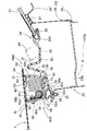
【図2】同実施形態の歩行者保護装置を搭載させた車両の平面図である。
【図3】同実施形態の歩行者保護装置の車両前後方向に沿った概略断面図であり、図2のIII−III部位に対応する。
【図4】同実施形態の歩行者保護装置の車両前後方向に沿った概略断面図であり、図2のIV−IV部位に対応する。
【図5】同実施形態の歩行者保護装置におけるフードパネルとボディ側との連結状態を示す概略図である。
【図6】同実施形態の歩行者保護装置におけるフードパネルとボディ側との連結状態を示す概略断面図であり、図5のVI−VI部位の断面図である。
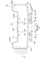
【図7】同実施形態の歩行者保護装置において使用されるエアバッグを単体で膨張させた状態を示す平面図である。
【図8】図7のVIII−VIII部位の断面図である。
【図9】同実施形態の歩行者保護装置において、エアバッグが膨張を完了させた状態の縦断面図である。
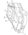
【図10】同実施形態の歩行者保護装置において、エアバッグが膨張を完了させた状態の車両の斜視図である。
【図11】本発明の他の実施形態の歩行者保護装置の車両前後方向に沿った概略断面図である。
【符号の説明】
1…ボディ、
3…フードパネル、
3a…後端、
3c…上面、
3d…後端面、
4…ヒンジ、
22…カウル、
23…カウルパネル、
28・82…カウルルーバ、
42・42A…ケース、
42b…開口、
48…エアバッグカバー、
57…インフレーター、
64…エアバッグ、
67c…フードパネル近傍部位、
74…テザー、
V…車両、
AS1・AS2…エアバッグ装置、
PM1・PM2…歩行者保護装置。[0001]
TECHNICAL FIELD OF THE INVENTION
The present invention relates to a walking device having an airbag that is inflated so as to protrude upward from a space between a hood panel and a windshield of a vehicle when an inflation gas flows, so that a pedestrian can be protected. Person protection device.
[0002]
[Prior art]
Conventionally, as a pedestrian protection device, an airbag is moved upward so as to lift a rear end side of a hood panel of a vehicle, and projects an airbag upward from a gap generated between the hood panel and a cowl louver. There is a configuration in which the upper side of a front pillar of a vehicle is covered with an airbag that has been inflated and inflated as described above (for example, see Patent Document 1). If the hood panel is moved upward so that the rear end of the hood panel is lifted, when the pedestrian interferes with the hood panel, the hood panel itself is easily plastically deformed. The shock at the time of interference can be absorbed. In addition, at the time of shock absorption, a cushion function of an actuator or the like that lifts the hood panel is often used together.
[0003]
[Patent Document 1]
JP-A-2000-79859 (FIGS. 22 and 28)
[0004]
[Problems to be solved by the invention]
However, in the conventional pedestrian protection device, the expanded and inflated airbag is configured to cover an upper surface or a rear end surface near a portion where an actuator for moving the hood panel to move upward so as to lift the rear end side thereof, The configuration is not such that it covers the vicinity of the rear end surface of the hood panel over substantially the entire length of the hood panel that has moved upward in the vehicle left-right direction. Therefore, there is a possibility that the pedestrian may interfere with the rear end surface of the hood panel.
[0005]
The present invention has been made to solve the above-described problem, and provides a pedestrian protection device capable of appropriately protecting a pedestrian by suppressing interference with the vicinity of a rear end surface of a hood panel that has moved upward. With the goal.
[0006]
[Means for Solving the Problems]
The pedestrian protection device according to the present invention, a hood panel that is movable upward on the rear end side,
An airbag device having an airbag that is swelled so as to protrude upward from between the hood panel and the windshield and that can protect pedestrians,
In a pedestrian protection device having a configuration including:
When the inflation is completed, the airbag is configured to be able to cover the entire length of the hood panel from the rear end surface to the upper surface of the hood panel that has moved upward in the vehicle left-right direction.
[0007]
In the pedestrian protection device having the above configuration, the airbag that has been inflated can cover the entire length of the hood panel from the rear end surface to the upper surface in the vehicle left-right direction. Therefore, even if the pedestrian interferes with the vicinity of the rear end face of the hood panel, the airbag can suppress the interference with the hood panel and protect the pedestrian accurately.
[0008]
Therefore, with the pedestrian protection device of the present invention, interference with the vicinity of the rear end surface of the hood panel that has moved upward can be suppressed, and the pedestrian can be protected accurately.
[0009]
Further, in the pedestrian protection device having the above-described configuration, a case for storing the airbag is disposed below and near the rear end of the hood panel,
It is preferable that the airbag is configured to be folded and stored in the case.
[0010]
With the above configuration of the pedestrian protection device, when the rear end of the hood panel moves, the airbag housed in the case also moves. That is, since the arrangement position of the airbag does not relatively change with respect to the hood panel, the rear edge of the raised hood panel can be reliably covered with the airbag whose inflation has been completed.
[0011]
Further, in the pedestrian protection device having the above configuration, the airbag is provided with a tether that regulates a shape when the inflation is completed,
It is preferable that the tether regulates a portion near the food panel in the airbag after the inflation is completed so as to be pulled toward the rear end of the food panel.
[0012]
If the pedestrian protection device is configured as described above, the airbag completes the inflation in a state where the airbag is pulled toward the rear end of the hood panel by the tether toward the area near the hood panel. The rear end surface of the hood panel can be reliably covered by the airbag.
[0013]
BEST MODE FOR CARRYING OUT THE INVENTION
Hereinafter, an embodiment of the present invention will be described with reference to the drawings. In addition, in this specification, the front-back direction is based on the direction along the front-rear direction of the vehicle, and the left-right direction is based on the direction along the left-right direction when viewing the rear side from the front side of the vehicle. .
[0014]
As shown in FIGS. 1 to 4, the pedestrian protection device PM1 of the embodiment includes a
[0015]
In the case of the embodiment, the airbag device AS1 is disposed at a position on the vehicle front side of the
[0016]
In the vehicle V, a
[0017]
In the case of the figure, the
[0018]
When the lifted
[0019]
The flip-up
[0020]
As shown in FIG. 2, the
[0021]
The
[0022]
The
[0023]
The
[0024]
In addition, the periphery of the
[0025]
As shown in FIGS. 3 and 4, the
[0026]
The
[0027]
The airbag cover 48 is made of a synthetic resin and is disposed so as to cover the
[0028]
As shown in FIGS. 3, 7, and 9, the
[0029]
The
[0030]
As shown in FIGS. 1, 2, 7, and 8, the
[0031]
As shown in FIGS. 1, 2, 7, and 10, the inflating
[0032]
On the
[0033]
At the
[0034]
Further, a
[0035]
Next, mounting of the pedestrian protection device PM1 of the embodiment on the vehicle V will be described. First, the
[0036]
After the
[0037]
Thereafter, the
[0038]
Then, the
[0039]
When the airbag device AS1 is mounted on the vehicle V, a lead wire (not shown) for operating the airbag is connected to the inflator 57 through a hole (not shown) provided in the
[0040]
After the pedestrian protection device PM1 is mounted on the vehicle V, if an operation signal is input to the inflator 57 and an actuator (not shown) disposed on the
[0041]
Also, in the pedestrian protection device PM1 of the embodiment, when the
[0042]
In the pedestrian protection device PM1 of the embodiment, the
[0043]
Therefore, in the pedestrian protection device PM1 of the embodiment, interference with the vicinity of the
[0044]
Further, the pedestrian protection device PM1 of the embodiment has a configuration in which the
[0045]
If this point is not taken into consideration, as shown in FIG. 11, a configuration in which the airbag device AS2 is fixed to the
[0046]
The
[0047]
The
[0048]
Of course, even when the pedestrian protection device PM2 is configured as described above, when the
[0049]
In the embodiment, the
[0050]
In the pedestrian protection devices PM1 and PM2 of the embodiment, the
[0051]
In the pedestrian protection devices PM1 and PM2 of the embodiment, the
[0052]
Further, in the embodiment, the
[Brief description of the drawings]
FIG. 1 is a side view of a vehicle equipped with a pedestrian protection device according to one embodiment of the present invention.
FIG. 2 is a plan view of a vehicle equipped with the pedestrian protection device of the embodiment.
FIG. 3 is a schematic cross-sectional view of the pedestrian protection device of the embodiment along the vehicle front-rear direction, and corresponds to a III-III part in FIG.
FIG. 4 is a schematic cross-sectional view of the pedestrian protection device of the embodiment along the vehicle front-rear direction, and corresponds to a portion IV-IV in FIG.
FIG. 5 is a schematic diagram showing a connection state between a hood panel and a body side in the pedestrian protection device of the embodiment.
FIG. 6 is a schematic cross-sectional view showing a connection state between a hood panel and a body side in the pedestrian protection device of the same embodiment, and is a cross-sectional view taken along the line VI-VI in FIG.
FIG. 7 is a plan view showing a state where the airbag used in the pedestrian protection device of the embodiment is inflated by itself.
FIG. 8 is a sectional view taken along the line VIII-VIII in FIG. 7;
FIG. 9 is a vertical cross-sectional view of the pedestrian protection device of the same embodiment in a state where the airbag has completed inflation.
FIG. 10 is a perspective view of the vehicle in a state where the airbag has completed inflation in the pedestrian protection device of the embodiment.
FIG. 11 is a schematic cross-sectional view along a vehicle front-rear direction of a pedestrian protection device according to another embodiment of the present invention.
[Explanation of symbols]
1 ... body,
3. Food panel,
3a ... rear end,
3c: upper surface,
3d ... rear end face,
4 ... hinge,
22 ... Cowl,
23 ... cowl panel,
28 ・ 82… Cowl louver,
42 ・ 42A… Case,
42b ... opening,
48 ... Airbag cover,
57 ... Inflator,
64 ... airbag,
67c: near the food panel,
74 ... Tether,
V… Vehicle,
AS1, AS2 ... airbag device,
PM1, PM2: Pedestrian protection devices.
Claims (3)
該フードパネルとフロントガラスとの間から、上方に向かって突出するように膨出して、歩行者を保護可能とされるエアバッグを有する、エアバッグ装置と、
を備える構成の歩行者保護装置において、
前記エアバッグが、膨張完了時において、上方に移動した前記フードパネルの後端面から上面にかけてを、前記フードパネルにおける車両左右方向の全長にわたって、覆い可能な構成とされていることを特徴とする歩行者保護装置。A hood panel that can move upward on the rear end side,
An airbag device having an airbag that is swelled so as to protrude upward from between the hood panel and the windshield and that can protect pedestrians,
In a pedestrian protection device having a configuration including:
When the inflation of the airbag is completed, the airbag is configured to be able to cover from the rear end surface of the hood panel moved upward to the upper surface over the entire length of the hood panel in the vehicle left-right direction. Person protection device.
前記エアバッグが、前記ケース内に、折り畳まれて収納されていることを特徴とする請求項1に記載の歩行者保護装置。A case for accommodating the airbag is disposed below and near the rear end of the hood panel,
The pedestrian protection device according to claim 1, wherein the airbag is folded and stored in the case.
該テザーが、膨張を完了させた前記エアバッグにおける前記フードパネル近傍部位を、前記フードパネル後端に向かって牽引するように、規制していることを特徴とする請求項1又は2に記載の歩行者保護装置。The airbag is configured to include a tether that regulates a shape when inflation is completed,
The said tether regulates so that the area | region near the said food panel in the said inflated airbag may be pulled toward the rear end of the said food panel, The Claim 1 or 2 characterized by the above-mentioned. Pedestrian protection device.
Priority Applications (1)
| Application Number | Priority Date | Filing Date | Title |
|---|---|---|---|
| JP2002333961A JP2004168111A (en) | 2002-11-18 | 2002-11-18 | Pedestrian protection device |
Applications Claiming Priority (1)
| Application Number | Priority Date | Filing Date | Title |
|---|---|---|---|
| JP2002333961A JP2004168111A (en) | 2002-11-18 | 2002-11-18 | Pedestrian protection device |
Publications (1)
| Publication Number | Publication Date |
|---|---|
| JP2004168111A true JP2004168111A (en) | 2004-06-17 |
Family
ID=32698526
Family Applications (1)
| Application Number | Title | Priority Date | Filing Date |
|---|---|---|---|
| JP2002333961A Withdrawn JP2004168111A (en) | 2002-11-18 | 2002-11-18 | Pedestrian protection device |
Country Status (1)
| Country | Link |
|---|---|
| JP (1) | JP2004168111A (en) |
Cited By (30)
| Publication number | Priority date | Publication date | Assignee | Title |
|---|---|---|---|---|
| JP2005178587A (en) * | 2003-12-19 | 2005-07-07 | Ashimori Ind Co Ltd | Air bag device for pedestrian |
| JP2006044289A (en) * | 2004-07-30 | 2006-02-16 | Toyoda Gosei Co Ltd | Airbag device for pedestrian |
| JP2006069349A (en) * | 2004-09-01 | 2006-03-16 | Nippon Plast Co Ltd | Airbag and protection device for non-occupant |
| JP2006096094A (en) * | 2004-09-28 | 2006-04-13 | Nippon Plast Co Ltd | Non-occupant impact protection device |
| JP2006096224A (en) * | 2004-09-30 | 2006-04-13 | Nippon Plast Co Ltd | Non-occupant protection device |
| JP2006219046A (en) * | 2005-02-14 | 2006-08-24 | Mazda Motor Corp | Pedestrian protection device for vehicles |
| JP2006240385A (en) * | 2005-03-01 | 2006-09-14 | Nippon Plast Co Ltd | Air bag device |
| JP2006306227A (en) * | 2005-04-27 | 2006-11-09 | Nippon Plast Co Ltd | Airbag device for protecting pedestrian and the like |
| JP2007001336A (en) * | 2005-06-21 | 2007-01-11 | Toyota Motor Corp | Hood airbag device |
| GB2433055A (en) * | 2005-12-09 | 2007-06-13 | Autoliv Dev | A bonnet mounted air-bag arrangement for protecting a pedestrian |
| JP2007153062A (en) * | 2005-12-02 | 2007-06-21 | Toyoda Gosei Co Ltd | Air-bag device for pedestrian |
| WO2007080690A1 (en) * | 2006-01-13 | 2007-07-19 | Takata Corporation | Pedestrian airbag device |
| JP2009143359A (en) * | 2007-12-13 | 2009-07-02 | Takata Corp | Airbag device |
| EP2495139A1 (en) * | 2011-03-01 | 2012-09-05 | Audi Ag | Motor vehicle with a front bonnet |
| DE102011101627A1 (en) | 2011-05-14 | 2012-11-15 | Audi Ag | Air bag device for use in passenger car, has supporting airbags filled with air before filling pane airbag or simultaneously filled with pane airbag such that bonnet is lifted by deformation in region at bonnet rear edge |
| DE102011101496A1 (en) | 2011-05-14 | 2012-11-15 | Audi Ag | Airbag device for vehicle i.e. passenger car, has wiper arm including ramp formed with ramp profile as strength contour free guide surface along length of wiper for deployment of airbag undisturbed by wiper device |
| CN103347745A (en) * | 2011-01-27 | 2013-10-09 | 高田股份公司 | Airbag arrangement for motor vehicle |
| WO2014139937A3 (en) * | 2013-03-11 | 2014-11-13 | Takata AG | Airbag module assembly for a motor vehicle |
| JP2015085867A (en) * | 2013-10-31 | 2015-05-07 | 豊田合成株式会社 | Airbag device for pedestrian |
| WO2015098890A1 (en) | 2013-12-24 | 2015-07-02 | トヨタ自動車株式会社 | Vehicular pedestrian-protecting airbag device |
| DE102014119337A1 (en) | 2013-12-26 | 2015-07-02 | Toyota Jidosha Kabushiki Kaisha | CONSTRUCTION FOR MOUNTING A PEDESTRIAN PROTECTION AGAINST A VEHICLE HOOD |
| JP2015137048A (en) * | 2014-01-23 | 2015-07-30 | トヨタ自動車株式会社 | Mounting structure of pedestrian protection airbag device for vehicles with hood |
| EP3056392A1 (en) | 2015-02-10 | 2016-08-17 | Toyota Jidosha Kabushiki Kaisha | Pedestrian protection airbag device |
| CN103347745B (en) * | 2011-01-27 | 2016-11-30 | 高田股份公司 | Air bag devices for motor vehicles |
| EP2360068B2 (en) † | 2009-12-14 | 2017-08-30 | Volvo Car Corporation | Vehicle airbag system |
| JP2017171030A (en) * | 2016-03-22 | 2017-09-28 | トヨタ自動車株式会社 | Pedestrian protection airbag device |
| JP2018172009A (en) * | 2017-03-31 | 2018-11-08 | 豊田合成株式会社 | Airbag device |
| GB2562716A (en) * | 2017-05-12 | 2018-11-28 | Jaguar Land Rover Ltd | A hood for a vehicle |
| DE102018008274B3 (en) * | 2018-10-18 | 2020-02-27 | Psa Automobiles Sa | Motor vehicle with a pedestrian airbag and water tank cover therefor |
| US10800458B2 (en) | 2019-02-14 | 2020-10-13 | Ford Global Technologies, Llc | Energy absorbing seal for a vehicle |
-
2002
- 2002-11-18 JP JP2002333961A patent/JP2004168111A/en not_active Withdrawn
Cited By (44)
| Publication number | Priority date | Publication date | Assignee | Title |
|---|---|---|---|---|
| JP2005178587A (en) * | 2003-12-19 | 2005-07-07 | Ashimori Ind Co Ltd | Air bag device for pedestrian |
| JP2006044289A (en) * | 2004-07-30 | 2006-02-16 | Toyoda Gosei Co Ltd | Airbag device for pedestrian |
| JP2006069349A (en) * | 2004-09-01 | 2006-03-16 | Nippon Plast Co Ltd | Airbag and protection device for non-occupant |
| JP2006096094A (en) * | 2004-09-28 | 2006-04-13 | Nippon Plast Co Ltd | Non-occupant impact protection device |
| JP2006096224A (en) * | 2004-09-30 | 2006-04-13 | Nippon Plast Co Ltd | Non-occupant protection device |
| JP2006219046A (en) * | 2005-02-14 | 2006-08-24 | Mazda Motor Corp | Pedestrian protection device for vehicles |
| JP2006240385A (en) * | 2005-03-01 | 2006-09-14 | Nippon Plast Co Ltd | Air bag device |
| JP2006306227A (en) * | 2005-04-27 | 2006-11-09 | Nippon Plast Co Ltd | Airbag device for protecting pedestrian and the like |
| JP2007001336A (en) * | 2005-06-21 | 2007-01-11 | Toyota Motor Corp | Hood airbag device |
| JP2007153062A (en) * | 2005-12-02 | 2007-06-21 | Toyoda Gosei Co Ltd | Air-bag device for pedestrian |
| GB2433055A (en) * | 2005-12-09 | 2007-06-13 | Autoliv Dev | A bonnet mounted air-bag arrangement for protecting a pedestrian |
| WO2007067121A1 (en) * | 2005-12-09 | 2007-06-14 | Autoliv Development Ab | An air-bag arrangement |
| JP2009518232A (en) * | 2005-12-09 | 2009-05-07 | オートリブ ディベロップメント エービー | Airbag device |
| JP2012126400A (en) * | 2005-12-09 | 2012-07-05 | Autoliv Development Ab | Airbag device |
| DE112006003329B4 (en) * | 2005-12-09 | 2015-07-09 | Autoliv Development Ab | The gas bag arrangement |
| WO2007080690A1 (en) * | 2006-01-13 | 2007-07-19 | Takata Corporation | Pedestrian airbag device |
| JP2009143359A (en) * | 2007-12-13 | 2009-07-02 | Takata Corp | Airbag device |
| EP2360068B2 (en) † | 2009-12-14 | 2017-08-30 | Volvo Car Corporation | Vehicle airbag system |
| EP2668071B1 (en) * | 2011-01-27 | 2017-06-21 | Takata AG | Airbag arrangements for motor vehicle |
| US9073513B2 (en) | 2011-01-27 | 2015-07-07 | Takata AG | Gas bag arrangements for a motor vehicle |
| CN103347745A (en) * | 2011-01-27 | 2013-10-09 | 高田股份公司 | Airbag arrangement for motor vehicle |
| JP2014503423A (en) * | 2011-01-27 | 2014-02-13 | タカタ アーゲー | Gas bag configuration for motor vehicles |
| US9994191B2 (en) | 2011-01-27 | 2018-06-12 | Takata AG | Gas bag arrangement for a motor vehicle |
| CN103347745B (en) * | 2011-01-27 | 2016-11-30 | 高田股份公司 | Air bag devices for motor vehicles |
| DE102011012692A1 (en) * | 2011-03-01 | 2012-09-06 | Audi Ag | Motor vehicle with a front flap |
| EP2495139A1 (en) * | 2011-03-01 | 2012-09-05 | Audi Ag | Motor vehicle with a front bonnet |
| DE102011101496A1 (en) | 2011-05-14 | 2012-11-15 | Audi Ag | Airbag device for vehicle i.e. passenger car, has wiper arm including ramp formed with ramp profile as strength contour free guide surface along length of wiper for deployment of airbag undisturbed by wiper device |
| DE102011101627A1 (en) | 2011-05-14 | 2012-11-15 | Audi Ag | Air bag device for use in passenger car, has supporting airbags filled with air before filling pane airbag or simultaneously filled with pane airbag such that bonnet is lifted by deformation in region at bonnet rear edge |
| WO2014139937A3 (en) * | 2013-03-11 | 2014-11-13 | Takata AG | Airbag module assembly for a motor vehicle |
| JP2015085867A (en) * | 2013-10-31 | 2015-05-07 | 豊田合成株式会社 | Airbag device for pedestrian |
| WO2015098890A1 (en) | 2013-12-24 | 2015-07-02 | トヨタ自動車株式会社 | Vehicular pedestrian-protecting airbag device |
| US9834172B2 (en) | 2013-12-24 | 2017-12-05 | Toyota Jidosha Kabushiki Kaisha | Vehicular pedestrian protecting airbag device |
| DE102014119337A1 (en) | 2013-12-26 | 2015-07-02 | Toyota Jidosha Kabushiki Kaisha | CONSTRUCTION FOR MOUNTING A PEDESTRIAN PROTECTION AGAINST A VEHICLE HOOD |
| DE102014119337B4 (en) * | 2013-12-26 | 2016-09-22 | Toyota Jidosha Kabushiki Kaisha | CONSTRUCTION FOR MOUNTING A PEDESTRIAN PROTECTION AGAINST A VEHICLE HOOD |
| JP2015137048A (en) * | 2014-01-23 | 2015-07-30 | トヨタ自動車株式会社 | Mounting structure of pedestrian protection airbag device for vehicles with hood |
| CN105857244A (en) * | 2015-02-10 | 2016-08-17 | 丰田自动车株式会社 | Pedestrian protection airbag device |
| EP3056392A1 (en) | 2015-02-10 | 2016-08-17 | Toyota Jidosha Kabushiki Kaisha | Pedestrian protection airbag device |
| US10000180B2 (en) | 2015-02-10 | 2018-06-19 | Toyota Jidosha Kabushiki Kaisha | Pedestrian protection airbag device |
| JP2017171030A (en) * | 2016-03-22 | 2017-09-28 | トヨタ自動車株式会社 | Pedestrian protection airbag device |
| JP2018172009A (en) * | 2017-03-31 | 2018-11-08 | 豊田合成株式会社 | Airbag device |
| GB2562716A (en) * | 2017-05-12 | 2018-11-28 | Jaguar Land Rover Ltd | A hood for a vehicle |
| GB2562716B (en) * | 2017-05-12 | 2020-02-12 | Jaguar Land Rover Ltd | A hood for a vehicle |
| DE102018008274B3 (en) * | 2018-10-18 | 2020-02-27 | Psa Automobiles Sa | Motor vehicle with a pedestrian airbag and water tank cover therefor |
| US10800458B2 (en) | 2019-02-14 | 2020-10-13 | Ford Global Technologies, Llc | Energy absorbing seal for a vehicle |
Similar Documents
| Publication | Publication Date | Title |
|---|---|---|
| JP2004168111A (en) | Pedestrian protection device | |
| JP4893043B2 (en) | Pedestrian airbag device | |
| JP3951747B2 (en) | Externally deployable airbag device | |
| KR100576595B1 (en) | Pedestrian protection airbag device | |
| US8016066B1 (en) | Pedestrian air bag | |
| AU2014385973B2 (en) | Pedestrian protecting air-bag device | |
| JP2008273250A (en) | Pedestrian airbag apparatus | |
| JP3969121B2 (en) | Pedestrian protection device | |
| JP2009120071A (en) | Pedestrian airbag device | |
| JP2003063334A (en) | Pedestrian protection airbag device | |
| JP2004299442A (en) | Pedestrian airbag device | |
| US10682978B2 (en) | Airbag device for pedestrian projection | |
| EP2105358B1 (en) | Airbag device | |
| JP4777282B2 (en) | Outside air bag device | |
| JP2019026223A (en) | Air bag device for non-occupant | |
| JP2003252138A (en) | Pedestrian airbag device | |
| JP3928442B2 (en) | Pedestrian airbag device | |
| JPH11208410A (en) | Head protection airbag device | |
| JP6070511B2 (en) | Pedestrian airbag device | |
| JP2018172006A (en) | Airbag device for pedestrian | |
| JP2006205934A (en) | Air bag and non-occupant protection device | |
| JP2006096289A (en) | Air bag device for pedestrian | |
| JP4391273B2 (en) | Airbag device | |
| JP2006035892A (en) | Pedestrian protection device | |
| JP3840933B2 (en) | Crew restraint system |
Legal Events
| Date | Code | Title | Description |
|---|---|---|---|
| A300 | Withdrawal of application because of no request for examination |
Free format text: JAPANESE INTERMEDIATE CODE: A300 Effective date: 20060207 |