JP2004176558A - Hose light emitter/charger - Google Patents
Hose light emitter/charger Download PDFInfo
- Publication number
- JP2004176558A JP2004176558A JP2002340730A JP2002340730A JP2004176558A JP 2004176558 A JP2004176558 A JP 2004176558A JP 2002340730 A JP2002340730 A JP 2002340730A JP 2002340730 A JP2002340730 A JP 2002340730A JP 2004176558 A JP2004176558 A JP 2004176558A
- Authority
- JP
- Japan
- Prior art keywords
- pressure chamber
- rotating shaft
- charging
- emitting
- hose
- Prior art date
- Legal status (The legal status is an assumption and is not a legal conclusion. Google has not performed a legal analysis and makes no representation as to the accuracy of the status listed.)
- Pending
Links
- 239000004065 semiconductor Substances 0.000 claims 1
- 239000008399 tap water Substances 0.000 abstract description 3
- 235000020679 tap water Nutrition 0.000 abstract description 3
- 230000005611 electricity Effects 0.000 abstract 1
- 238000005381 potential energy Methods 0.000 abstract 1
- 238000010248 power generation Methods 0.000 abstract 1
- XLYOFNOQVPJJNP-UHFFFAOYSA-N water Substances O XLYOFNOQVPJJNP-UHFFFAOYSA-N 0.000 abstract 1
- 239000012530 fluid Substances 0.000 description 3
- 238000010586 diagram Methods 0.000 description 2
Images


Classifications
-
- Y—GENERAL TAGGING OF NEW TECHNOLOGICAL DEVELOPMENTS; GENERAL TAGGING OF CROSS-SECTIONAL TECHNOLOGIES SPANNING OVER SEVERAL SECTIONS OF THE IPC; TECHNICAL SUBJECTS COVERED BY FORMER USPC CROSS-REFERENCE ART COLLECTIONS [XRACs] AND DIGESTS
- Y02—TECHNOLOGIES OR APPLICATIONS FOR MITIGATION OR ADAPTATION AGAINST CLIMATE CHANGE
- Y02E—REDUCTION OF GREENHOUSE GAS [GHG] EMISSIONS, RELATED TO ENERGY GENERATION, TRANSMISSION OR DISTRIBUTION
- Y02E10/00—Energy generation through renewable energy sources
- Y02E10/20—Hydro energy
-
- Y—GENERAL TAGGING OF NEW TECHNOLOGICAL DEVELOPMENTS; GENERAL TAGGING OF CROSS-SECTIONAL TECHNOLOGIES SPANNING OVER SEVERAL SECTIONS OF THE IPC; TECHNICAL SUBJECTS COVERED BY FORMER USPC CROSS-REFERENCE ART COLLECTIONS [XRACs] AND DIGESTS
- Y02—TECHNOLOGIES OR APPLICATIONS FOR MITIGATION OR ADAPTATION AGAINST CLIMATE CHANGE
- Y02E—REDUCTION OF GREENHOUSE GAS [GHG] EMISSIONS, RELATED TO ENERGY GENERATION, TRANSMISSION OR DISTRIBUTION
- Y02E60/00—Enabling technologies; Technologies with a potential or indirect contribution to GHG emissions mitigation
- Y02E60/10—Energy storage using batteries
Landscapes
- Hydraulic Turbines (AREA)
- Other Liquid Machine Or Engine Such As Wave Power Use (AREA)
- Secondary Cells (AREA)
Abstract
Description
【0001】
【発明の属する技術分野】
本発明は、小水力の利用による発電で、フォトダイオードを発光し充電可能電池の充電作用を行うものである。
【0002】
【従来の技術】
従来、この種の装置は小エネルギーで効率が良くないという点で無視されてきた。従って、未開発の分野である。
【0003】
【発明が解決しようとする課題】
小エネルギーの利用と小エネルギーの保存装置を提供することにある。
【0004】
【課題を解決するための手段】
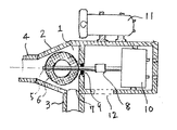
上記目的を達成するための手段として、この発明は図1に示すように、円錐状高圧室1を有するケーシング2に当該高圧室に連通する導流管3を連設し、かつ同高圧室の中心線に沿って排出管4を連設し、軸受9より回転軸5をワッシャー型羽根6を植設した回転軸5を高圧室内に配置し、高圧室から軸受9を通り外部に突き出た回転軸5に発電機10をジョイント8を介して接続し、発生した電力で発光と充電可能電池の充電を作動する。
【0005】
【発明の実施の形態】
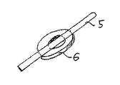
発明の実施の形態を実施例に基づき図面を参照して説明すると、図1はホース発光・充電器の正断面図、図2は円錐状高圧室1と導流管3および回転軸5の構成図、図3は回転軸5とワッシャー型羽根6の実施例を示す斜視図、図4は発電機とダイオード及び充電可能電池の接続の実施例を示す配線図である。
【0006】
図1において、円錐状高圧室1を有するケーシング2には高圧流体を導くため導流管3が連設されて、高圧室1の中心線に沿って排出管4が連設されている。また同高圧室内にワッシャー型羽根6を固着した回転軸5が軸受9に支障され回転自在に支持されている。
【0007】
次に、導流管3より送り込まれた高圧流体は、円錐状高圧室に流入し、渦上に回転しながら排出管4より流出する。回転軸5に固着された羽根6が渦流の中にあって渦流を回転力として変換し回転軸5に伝達される。
【0008】
上述のように円錐状高圧室1において流体の圧力エネルギーは運動エネルギーに変換され、回転軸5はジョイント8を介して発電機10と連結されている。
【0009】
【発明の効果】
本発明は、以上説明したように構成されているので、以下に記載されるような効果を奏する。
【0010】
水道水の利用は普通のホースとほぼ同じ利用が出来、夜間は照明、昼間は充電可能電池の充電として利用出来る効果がある。
【0011】
そして、このような効果を有することにより、この発明に係わるホース発光・充電器は、簡単な構造で、小型化できるなどの効果がある。
【図面の簡単な説明】
【図1】ホース発光・充電器の正断面図である。
【図2】円錐状高圧室・導流管・排出管の構成図である。
【図3】回転軸・ワッシャー型羽根の構成斜視図である。
【図4】発電機とダイオード及び充電可能電池の接続実施を示す配線図である。
【符号の説明】
1 円錐状高圧室
2 ケーシング
3 導流管
4 排出管
5 回転軸
6 ワッシャー型羽根
7 導流管と円錐状高圧室との境界面
8 ジョイント
9 軸受
10 発電機
11 フォトダイオード付充電用電池箱
12 窓[0001]
TECHNICAL FIELD OF THE INVENTION
The present invention is to generate light by using a small hydraulic power to emit light from a photodiode to perform a charging operation of a rechargeable battery.
[0002]
[Prior art]
Heretofore, this type of device has been neglected in that it is low energy and inefficient. Therefore, it is an undeveloped field.
[0003]
[Problems to be solved by the invention]
An object of the present invention is to provide a device for using and saving small energy.
[0004]
[Means for Solving the Problems]
As a means for achieving the above object, the present invention, as shown in FIG. 1, includes a
[0005]
BEST MODE FOR CARRYING OUT THE INVENTION
FIG. 1 is a front sectional view of a hose light emitting / charging device, and FIG. 2 is a configuration of a conical high-pressure chamber 1, a flow guide tube 3, and a rotating shaft 5. FIG. 3 is a perspective view showing an embodiment of the rotating shaft 5 and the washer-type blade 6, and FIG.
[0006]
In FIG. 1, a
[0007]
Next, the high-pressure fluid sent from the flow guide pipe 3 flows into the conical high-pressure chamber, and flows out from the
[0008]
As described above, the pressure energy of the fluid is converted into kinetic energy in the conical high-pressure chamber 1, and the rotating shaft 5 is connected to the
[0009]
【The invention's effect】
The present invention is configured as described above, and has the following effects.
[0010]
Tap water can be used in almost the same way as a normal hose, and it has the effect of being used for lighting during the night and charging a rechargeable battery during the day.
[0011]
By having such an effect, the hose light emitting / charging device according to the present invention has effects such as a simple structure and downsizing.
[Brief description of the drawings]
FIG. 1 is a front sectional view of a hose light emission / charger.
FIG. 2 is a configuration diagram of a conical high-pressure chamber, a flow guide tube, and a discharge tube.
FIG. 3 is a configuration perspective view of a rotary shaft / washer type blade.
FIG. 4 is a wiring diagram showing a connection between a generator, a diode, and a rechargeable battery.
[Explanation of symbols]
DESCRIPTION OF SYMBOLS 1 Conical high-
Claims (1)
(2)ケーシング2の軸受9より外部に突き出た回転軸5にジョイント8を介して発電機10を連設しさらにフォトダイオード付き電池ボックス11を接続することを特徴とするホース発光・充電器。
(3)発電機10に充電可能な電池を半導体ダイオードに接続し、発光と充電可能な回路とすることを特徴とするホース発光・充電器。
以上、(1)、(2)、(3)、の構成からなる装置を特徴とするホース発光・充電器。(1) A flow guide pipe 3 communicating with the high pressure chamber is connected to the conical high pressure chamber 1 casing 2 and a discharge pipe 4 is connected to the tip of the conical high pressure chamber along the center line thereof. On the opposite side of the discharge pipe, a wall having a bearing 9 disposed at the center is continuously provided, and a rotating shaft 5 is inserted and supported in the high-pressure chamber, and a washer-type blade 6 fixed to the rotating shaft is disposed in the high-pressure chamber 1. A hose light-emitting / charging device characterized in that a rotating force is taken out from the rotating shaft 5 to the outside.
(2) A hose light-emitting / charging device characterized by connecting a generator 10 to a rotating shaft 5 protruding outside from a bearing 9 of a casing 2 via a joint 8 and further connecting a battery box 11 with a photodiode.
(3) A hose light emitting / charging device characterized in that a battery capable of charging the generator 10 is connected to a semiconductor diode to form a circuit capable of charging and emitting light.
As described above, a hose light emitting / charging device characterized by the device having the configuration of (1), (2), or (3).
Priority Applications (1)
| Application Number | Priority Date | Filing Date | Title |
|---|---|---|---|
| JP2002340730A JP2004176558A (en) | 2002-11-25 | 2002-11-25 | Hose light emitter/charger |
Applications Claiming Priority (1)
| Application Number | Priority Date | Filing Date | Title |
|---|---|---|---|
| JP2002340730A JP2004176558A (en) | 2002-11-25 | 2002-11-25 | Hose light emitter/charger |
Publications (1)
| Publication Number | Publication Date |
|---|---|
| JP2004176558A true JP2004176558A (en) | 2004-06-24 |
Family
ID=32703274
Family Applications (1)
| Application Number | Title | Priority Date | Filing Date |
|---|---|---|---|
| JP2002340730A Pending JP2004176558A (en) | 2002-11-25 | 2002-11-25 | Hose light emitter/charger |
Country Status (1)
| Country | Link |
|---|---|
| JP (1) | JP2004176558A (en) |
Cited By (4)
| Publication number | Priority date | Publication date | Assignee | Title |
|---|---|---|---|---|
| JP2007157675A (en) * | 2005-12-06 | 2007-06-21 | Akira Narisada | Storage battery |
| CN103967688A (en) * | 2014-05-09 | 2014-08-06 | 东莞市光能新能源科技有限公司 | Water flow power generation device |
| WO2019082822A1 (en) * | 2017-10-23 | 2019-05-02 | 櫻護謨株式会社 | Water feed hose provided with power supply, and intermediary unit |
| WO2026044874A1 (en) * | 2024-08-28 | 2026-03-05 | 泰铂(上海)环保科技股份有限公司 | Heating system |
-
2002
- 2002-11-25 JP JP2002340730A patent/JP2004176558A/en active Pending
Cited By (5)
| Publication number | Priority date | Publication date | Assignee | Title |
|---|---|---|---|---|
| JP2007157675A (en) * | 2005-12-06 | 2007-06-21 | Akira Narisada | Storage battery |
| CN103967688A (en) * | 2014-05-09 | 2014-08-06 | 东莞市光能新能源科技有限公司 | Water flow power generation device |
| WO2019082822A1 (en) * | 2017-10-23 | 2019-05-02 | 櫻護謨株式会社 | Water feed hose provided with power supply, and intermediary unit |
| JP2019078310A (en) * | 2017-10-23 | 2019-05-23 | 櫻護謨株式会社 | Water hose mounted with power source and medium unit |
| WO2026044874A1 (en) * | 2024-08-28 | 2026-03-05 | 泰铂(上海)环保科技股份有限公司 | Heating system |
Similar Documents
| Publication | Publication Date | Title |
|---|---|---|
| US20080219831A1 (en) | Pipe flow-driven power generator | |
| CN201333101Y (en) | Self-generating dental turbine lighting mobile phone | |
| JPH0842440A (en) | Generating set by means of water current of service water pipe | |
| EA014944B1 (en) | The tube for transforming the fluid flow power into the electrical power | |
| JP2004176558A (en) | Hose light emitter/charger | |
| AR026378A1 (en) | DEVICE FOR GENERATING ELECTRICAL VOLTAGE FOR COMPONENT ELEMENTS OF A GAS HEATER WATER HEATER | |
| CN209976686U (en) | A new type of water turbine device | |
| MY136405A (en) | Turbine with a tube connected downstream | |
| CN209762917U (en) | Fountain decorative lamp and fountain pool | |
| CN203218992U (en) | Water tank structure of wireless power transmission device | |
| RU2007106384A (en) | HYDRAULIC DRIVE | |
| CN101498272A (en) | Power generation method and apparatus by improving tap water flow velocity | |
| CN107939578A (en) | A kind of Archimedian screw wheel water pipe generating set of interior water receiving pipe | |
| CN221965771U (en) | A spray gun with power generation and lighting mechanism | |
| CA2581559A1 (en) | Pipe flow-driven power generator | |
| CN221879584U (en) | A low-pressure water flow generator device | |
| TWI625445B (en) | Irrigation system using green energy | |
| CN201441957U (en) | Light displaying device of shower head | |
| CN201304374Y (en) | Light-emitting shower head | |
| CN205887238U (en) | High efficiency low noise gondola water faucet that gives out light; give off light | |
| CN2435540Y (en) | Generating device using wave energy | |
| CN215909002U (en) | Low-medium pressure lighting device based on gas flow | |
| CN207823229U (en) | A kind of air-breathing luminous sprinkler | |
| CN201688358U (en) | AC light emitting diode lamp and device with same | |
| CN201202978Y (en) | Improved structure of lighting device |