JP2004187902A - Game machine - Google Patents
Game machine Download PDFInfo
- Publication number
- JP2004187902A JP2004187902A JP2002358981A JP2002358981A JP2004187902A JP 2004187902 A JP2004187902 A JP 2004187902A JP 2002358981 A JP2002358981 A JP 2002358981A JP 2002358981 A JP2002358981 A JP 2002358981A JP 2004187902 A JP2004187902 A JP 2004187902A
- Authority
- JP
- Japan
- Prior art keywords
- game board
- fastener
- base frame
- fastening
- handle
- Prior art date
- Legal status (The legal status is an assumption and is not a legal conclusion. Google has not performed a legal analysis and makes no representation as to the accuracy of the status listed.)
- Granted
Links
- 239000011521 glass Substances 0.000 description 14
- 238000006243 chemical reaction Methods 0.000 description 10
- 238000005034 decoration Methods 0.000 description 9
- 238000000034 method Methods 0.000 description 5
- 238000010304 firing Methods 0.000 description 4
- 238000006073 displacement reaction Methods 0.000 description 3
- 238000005516 engineering process Methods 0.000 description 3
- 210000000078 claw Anatomy 0.000 description 2
- 230000000694 effects Effects 0.000 description 2
- 230000005484 gravity Effects 0.000 description 2
- 230000007704 transition Effects 0.000 description 2
- 125000002066 L-histidyl group Chemical group [H]N1C([H])=NC(C([H])([H])[C@](C(=O)[*])([H])N([H])[H])=C1[H] 0.000 description 1
- 238000010586 diagram Methods 0.000 description 1
- 238000000605 extraction Methods 0.000 description 1
- 239000000463 material Substances 0.000 description 1
- 230000002093 peripheral effect Effects 0.000 description 1
Images





Landscapes
- Pinball Game Machines (AREA)
Abstract
Description
【0001】
【発明の属する技術分野】
本発明は、遊技機の特徴部分となる遊技盤をその本体に対して脱着可能とした遊技機に関する。
【0002】
【従来の技術】
この種の遊技機に関する従来技術として、遊技機本体の保持枠に対して遊技盤が脱着交換可能に保持されたパチンコ遊技機がある(例えば、特許文献1,2参照。)。この公知のパチンコ遊技機は複数の施錠具を備えており、これら施錠具は保持枠内のセット開口域に形成された支持孔に回動可能に嵌め合わされている。そして、遊技盤を保持枠にセットした状態で施錠具を回動させると、その施錠部分が弾性的に係合して遊技盤を保持することができる。その一方で、遊技盤には遊技領域の外周を取り囲む案内レール(または球寄せカバー)の上端部分に取っ手が設けられており、遊技盤を保持枠から出し入れする際は、その取っ手に指をかけて作業を行うことができるものとなっている。
【0003】
【特許文献1】
特開平9−262354号公報(第5頁、図3、図18)
【特許文献2】
特許第2984821号公報(第5−6頁、図3、図18)
【0004】
【発明が解決しようとする課題】
上述した公知のパチンコ遊技機は、脱着交換式遊技盤の取り扱い技術とその固定化技術という2つの技術に関し、第1には遊技盤に取っ手を設けることでその出し入れを容易化し、また第2には施錠具を予め保持枠(支持孔)に取り付けておくことで保持枠から施錠具が分離するのを抑えるとともに、部品点数の削減や構造の簡素化等を図ろうとしたものと認められる。
【0005】
しかしながら、このような取っ手や施錠具はあくまで個別かつ単独に機能しているに過ぎず、これらが協働して機能するものではない。例えば、遊技盤の取り付けの際に遊技盤を保持枠のセット開口域に入れ込むと、その時点で取っ手の役目は既に終わっており、この後、施錠具の回動による遊技盤の固定化作業に関して取っ手が特段の作用をなすことはない。逆に、遊技盤の取り外しの際に施錠具の係合を解除する作業において、取っ手はそれ単独で何ら機能しておらず、全ての施錠具を解除した後、次に作業の対象が遊技盤の抜き出しに移ったときに初めて取っ手として機能し得る。このため公知のパチンコ遊技機は、取っ手と施錠具という個別・独立の要素が単に寄り集まって成立しているだけであり、具体的手段としての合理性に欠けるという問題がある。
【0006】
そこで本発明は、遊技盤の取り付けとその固定、または、遊技盤の固定解除とその取り外しの作業を行う際に、個別の要素を協働させることで具体的手段としての合理性を求めようとするものである。
【0007】
【課題を解決するための手段】
本発明の遊技機は、手指が入る隙間を設けて遊技盤を基枠に締め付ける手段を採用することで上記の課題を解決している(解決手段1)。遊技機の具体的な構成は、遊技盤を嵌め込み可能な基枠と、遊技盤に設けられた手指が入る隙間と、遊技盤を基枠に締め付ける締付手段とを備えたものとなる。
【0008】
本発明の遊技機によれば、隙間に手指を挿入して遊技盤を基枠に嵌め込むことができるし、また、隙間に手指を挿入したまま遊技盤を基枠に締め付けることができる。この場合、手指が入る隙間は取っ手として機能するので、遊技盤を基枠に嵌め込む作業および遊技盤を基枠に締め付ける作業のいずれにおいても隙間が取っ手として機能し得る。すなわち、遊技盤を基枠に取り付ける際は、作業者が隙間に手指を入れることで遊技盤の取り扱いが容易となる。さらに遊技盤を基枠に固定する際は、その隙間に入れた手指で締付作業を行うことができるので、ここでは隙間が締付具としても機能することで遊技盤の締め付け作業を容易にする。
【0009】
このように、本発明の遊技機は遊技盤の取り扱い作業および締め付け作業のいずれにおいても手指が入る隙間を有効に活用することで、具体的手段としての合理性を実現している。また本発明では、隙間に手指を入れて遊技盤を基枠に嵌め込んだ後、そのまま締め付け作業にスムーズに移ることができるため、遊技盤の取り付け作業が簡素化されるとともに、作業の合理化・効率化をも達成する。
【0010】
さらに本発明の遊技機は、締付手段による遊技盤の締め付けを解除する解除手段を備えることができる(解決手段2)。この場合、隙間に手指を入れて遊技盤の締め付けを解除した後、次にその手指を隙間に入れたまま遊技盤を基枠から抜き取る作業にスムーズに移行することができる。また遊技盤を抜き取った後は、隙間に手指を入れて遊技盤の取り扱い(運搬)作業を行うことができるので、遊技盤の取り外し作業においても簡素化や合理化・効率化が図られる。
【0011】
本発明の遊技機はより具体的な構成として、遊技盤をその前後の一方向から受け入れて嵌め込み可能な基枠と、遊技盤の周縁部に設けられ、遊技盤から突き出る突出位置と遊技盤に向けて畳み込まれた畳込位置との間で変位し、その突出位置にあるとき遊技盤の取っ手となる一方、遊技盤が基枠に嵌め込まれた状態で畳込位置に変位することにより遊技盤を基枠に対して締め付ける締付具とを備えることができる(解決手段3)。
【0012】
上述した締付具は、突出位置と畳み込み位置との間で変位可能であり、その位置に応じて複数の用途・機能を兼ね備える。具体的には、上述の突出位置では締付具が遊技盤から突出した姿勢(例えば遊技盤面から手前側に突き出た状態や遊技盤の外方へ張り出した状態のいずれであってもよい)にあって、この状態で締付具は、遊技盤を取り扱うための取っ手となっている。したがって作業者は、突出位置にある締付具を把持することで遊技盤の持ち運びや基枠への嵌め込み作業を容易に行うことができる。
【0013】
また遊技盤を基枠に嵌め込んだ状態で、その突出位置にある締付具を畳込位置に向けて変位させることで遊技盤の締め付けを行うことができる。このとき作業者は、遊技盤の締め付け作業においても締付具を取っ手、つまり、作業の力を加える対象として機能させることができるので、遊技盤の締め付け作業を容易に行うことができるし、遊技盤の嵌め込み作業から締め付け作業への移行もスムーズに行うことができる。
【0014】
逆に、遊技盤の取り外し作業においては、締付具をその畳込位置から突出位置に向けて変位させることで、その締め付けを容易に解除することができる。このとき作業者は、締め付けを解除する際の取っ手として締付具を機能させることができるし、また締め付けを解除した後は、締付具をそのまま取っ手として機能させることで遊技盤の抜き取りや持ち運びを容易に行うことができる。したがって、遊技盤の取り外し作業から取り扱い作業への移行もまたスムーズに行うことができる。
【0015】
より好ましくは、上述した締付具は、遊技盤に基端が回動自在に支持され、この基端から回動軸線を挟んで両方向に延びる本体と、この本体の一端に形成されて取っ手となる部位と、本体の他端に形成され、この本体の回動に伴い畳込位置に変位することで遊技盤の締め付けをなす締付部位とを含む。また、これに合わせて基枠は、締結具が畳込位置に向けて変位されるとき、その締付部位を受け入れる受入溝と、この受入溝内に形成され、締結具が畳込位置まで変位したとき締付部位に当接することで締付具に遊技盤の締め付けのための反力を付与する当接部とを有する(解決手段4)。
【0016】
このような構成の場合、締付具の本体がその基端を中心として回動することで、突出位置と畳込位置との間での変位を可能とする。このとき本体の一端の部位が取っ手となり、作業者はこの部位を把持して遊技盤の取り扱い作業や基枠への嵌め込み作業を行うことができる。また遊技盤を締め付ける際、作業者は取っ手となる部位に力を加えて締付具を畳込位置に向けて回動させ、その他端に形成された締付部位を受入溝内に入り込ませることができる。この後、締付具が畳込位置まで変位して締付部位が受入溝内で当接部に当接すると、そこからの反力が遊技盤の締め付け力として作用するので、この時点で遊技盤の締め付け作業が完了する。
【0017】
これとは逆に、遊技盤の締め付けを解除する際は、畳込位置にある締付具の一端の部位が作業用の取っ手となる。この場合、作業者はこの部位に力を加えて締付具を突出位置に向けて回動させることで、他端の締付部位を受入溝内の当接部から容易に引き離すことができる。また締付部位が当接部から離れると、そこから受ける反力が消滅して遊技盤の締め付けが解除される。また締付具をさらに回動させると、締付部位が受入溝から抜け出し可能となるので、この状態で作業者は、取っ手となる部位を把持したまま遊技盤の取り外し作業を行うことができる。また遊技盤を基枠から取り外した後は、取っ手となる部位を把持したまま遊技盤の持ち運びを行うことができる。
【0018】
上述の態様では締結具の本体が回動可能であるため、突出位置と畳込位置との間の変位がスムーズに行われるし、その回動を利用して遊技盤の締め付けとその解除を行うことができるため、きわめて機能的・合理的な構造となる。また本体には、回動中心を挟んでその両端に取っ手となる部位と締付部位とがそれぞれ形成されているため、一端側と他端側とのレバー比を適切に設定することで遊技盤の締め付け力を所望に設定することができる。
【0019】
また、上述のように締付具の締付部位が受入溝内の当接部に当接したとき、この当接部は遊技盤の基枠への嵌め込み方向およびこれに直交する方向の2方向へ反力を付与することができる(解決手段5)。例えば、遊技盤が基枠の前側から嵌め込まれる態様の場合、当接部からの反力は遊技盤を基枠の奥へ押し込む方向と基枠の内縁に対して押し付ける方向の2方向に働いてその締め付けを行うことができる。また、遊技盤が基枠の後側から嵌め込まれる態様の場合、反力は遊技盤を手前へ押し出す方向と基枠の内縁に対して押し付ける方向の2方向に働いてその締め付けを行うことができる。
【0020】
より好ましくは、締付具が遊技盤の上縁部に設けられていてもよいし(解決手段6)、あるいは遊技盤の隅角部に設けられていてもよい(解決手段7)。前者の場合、遊技盤の持ち運びの際はその上部で締付具を把持する態様となり、後者の場合は遊技盤の隅角部で締付具を把持する態様となる。いずれの場合も、遊技盤を吊り下げた格好で持ち運びできるので、取り扱い時に遊技盤の姿勢が安定化する。特に後者では、取っ手として把持する位置と遊技盤の重心位置とが略対角線上に並ぶため、持ち運びの際にきわめて合理的な態様となる。
【0021】
また遊技盤の隅角部は通常、遊技領域の外に位置しており、この隅角部に締付具を設ける態様では、取っ手となる部材が遊技者から見えないか、あるいはその注意を引きにくい位置にあるため遊技機の見栄えを損なうことはない。また、外形が略矩形をなす遊技盤においては、遊技領域外の隅角部が充分なスペースを有しているため、このような隅角部に締付具を設ける態様では比較的大きな構造を確保することができる。このため締付具を把持しやすい大きさに加工できるし、また締付具が大きく強固な構造となる分、必要充分な締め付け力を発揮することができる。
【0022】
また遊技盤は、その中央に形成された遊技領域と、この遊技領域外に配置された装飾部とを含んでおり、この装飾部に締結具が設けられている態様であってもよい(解決手段8)。例えば、パネル飾りやコーナ飾りと称される装飾部が遊技盤に付される態様では、これら装飾部に予め締結具を設けておくことで締結具の取り付けを容易にすることができる。またこの場合、締結具を装飾部と一体にして遊技盤に取り付けることができるため、別途、締結部と基枠(受入溝)との位置合わせを考慮する必要がない。
【0023】
【発明の実施の形態】
本発明の好適な実施の形態としては、例えばパチンコ遊技やアレンジボール遊技を提供するパチンコ遊技機を挙げることができる。以下、パチンコ遊技機を例に挙げて本発明の一実施形態について説明する。
【0024】
図1は、一実施形態のパチンコ遊技機1を示している。このパチンコ遊技機1は外枠2を備え、この外枠2内に基枠4が取り付けられている。また、基枠4には遊技盤6が取り付けられており、この遊技盤6の盤面構成によりパチンコ遊技機1の機種が特徴付けられている。
【0025】
遊技盤6は略矩形をなし、その中央に遊技領域8が形成されている。公知のように、遊技領域8はその周りを案内レール10に囲まれ、その略中心部にセンター役物12が設けられている。その他、遊技領域8内には障害釘や風車、入賞口等の盤面構成要素が配置されているが、これらについては特に説明を要しないためその図示も省略する。
【0026】
また、外枠2には前面枠14が取り付けられており、この前面枠14は図示しない電飾装置のほか、その下部に発射ハンドル16や下皿18等を有している。また、前面枠14にはガラス枠20がヒンジを介して取り付けられており、図示のように、ガラス枠20はパチンコ機1の前面にて横方向に開閉可能となっている。
【0027】
図1ではガラス枠20が開いた状態で示されており、それゆえガラス枠20の背面が露出して示されている。ガラス枠20はその中央にガラス面22を有しており、ガラス枠20を閉じた状態ではガラス面22内に遊技領域8が覆われるものとなっている。またガラス枠20の背面にはガラス面22の下方に発射レール24が配置されており、ガラス枠20を閉じた状態で、発射レール24は遊技盤6の案内レール10に連なる。なお図1では隠れているが、ガラス枠20の正面側にはガラス面22の下方に上皿が配置されている。
【0028】
図2は、上述した基枠4への遊技盤6の取り付けを具体的に示し、この図2ではガラス枠20が省略されている。基枠4には遊技盤支持部材26が取り付けられており、この遊技盤支持部材26は基枠4の一側縁部(図2の例では左側縁部)に配置されている。遊技盤支持部材26は基枠4の左側縁部に沿って上下方向に延び、その上下端はいずれもヒンジピン28を介して基枠4に連結されている。これらヒンジピン28は遊技盤支持部材26の上下端からそれぞれ突出し、基枠4に対して遊技盤支持部材26を水平方向に回動可能としている。
【0029】
なお、遊技盤支持部材26はその長手方向(この例では上下方向)でみて溝形状の断面を有し、その内側に遊技盤6の一側縁部(この例では左側縁部)を受け入れ可能となっている。また遊技盤支持部材26は、その上下端に支持プレート26a,26bを有しており、これら支持プレート26a,26b間に遊技盤6を挟み込んで遊技盤6を支持し、その重量を受け持ったまま基枠4に対して回動することができる。
【0030】
基枠4はその内側に開口4aを有しており、この開口4aは遊技盤6の外形に合わせた形状をなしている。このため図2に示されるように、遊技盤6は開口4aにぴったり嵌り込んだ状態で基枠4に取り付けられている。開口4aの下縁部には2つのロック部材30,32が設けられており、これらロック部材30,32は基枠4の幅方向に間隔をおいて配置されている。また、これらロック部材30,32はいずれも垂直面内にて回動自在に支持されている。
【0031】
このうち一方(この例では左方)のロック部材30は、例えば2本羽根のプロペラ形状をなし、図示のように縦長となる姿勢で遊技盤6を係止することができる。より詳しくは、遊技盤6の下端部に係止部34が設けられており、この係止部34は遊技盤6から手前側に突出して形成されている。一方、図1に示されるように、ロック部材30の両端にはそれぞれ係止部34に対応したかぎ爪30aが形成されており、ロック部材30はそのかぎ爪30aを係止部34の上端に引っ掛けることで遊技盤6を係止することができる。なお、もう一方のロック部材32も同様に図示の位置で遊技盤6を係止しているが、ここではその具体的な説明を省略する。
【0032】
ここで遊技盤6には、その上縁部、特にその一隅角部(この例では右上隅角部)に締付具40が設けられている。一方、基枠4には締付具40に対応する位置に受け座42が設けられており、この受け座42は上述の開口4aの右上隅に位置している。本実施形態のパチンコ遊技機1は、上述のロック部材30,32の他に締付具40を用いて遊技盤6を基枠4に対して締め付け可能となっており、以下、この締付具40について詳しく説明する。
【0033】
図3は、遊技盤6を基枠4から取り外した状態、つまり、遊技盤6を単独で示している。締付具40は遊技盤6の前面にて上下方向に回動可能となっており、この回動に伴い、図3に示されるように締付具40を上方へ跳ね上げることができる。この状態では締付具40が遊技盤6の上端縁から上方に張り出した状態(突出位置)にあり、逆に図2に示されるように下方へ回動された状態では、締付具40が遊技盤6に向けて畳み込まれた状態(畳込位置)にある。
【0034】
また図3に示されるように、締付具40を跳ね上げた状態で作業者がこれを把持し、そのまま遊技盤6を持ち運ぶことができる。上述のように締付具40は遊技盤6の右上の隅角部(以下、単に「コーナ部」と略称する。)に設けられているため、図3の状態から遊技盤6が持ち上げられると、遊技盤6は締付具40を中心として全体的に一方向(この例では反時計回り方向)へ回動し、その重心が右上のコーナ部の略真下に位置するものとなる。
【0035】
図4および図5は、締付具40をより詳しく示している。締付具40は門形状の本体を有し、この本体は主に両側一対の桁部40aおよび取っ手部40bから構成されている。両側一対の桁部40aは遊技盤6の幅方向に間隔をおいて互いに平行に配置されており、その間に取っ手部40bが掛け渡された状態にある。また締付具40はヒンジ軸40cを有しており、このヒンジ軸40cもまた一対の桁部40aの間に掛け渡されている。なお、取っ手部40bとヒンジ軸40cとの間にクロスメンバ40dが設けられており、このクロスメンバ40dもまた、一対の桁部40aの間に掛け渡されている。
【0036】
一方、遊技盤6はその右上のコーナ部に2つの切欠6a,6bを有している。このうち内側寄りの切欠6aは長細いU字形状をなし、遊技盤6の上端縁から下方へ向けて延びている。これら切欠6a,6bの間隔は桁部40aの間隔よりも僅かに小さく、それゆえ遊技盤6の正面からみて、一対の桁部40a,40bはそれぞれ対応する切欠6a,6b内に位置づけられている。
【0037】
また、遊技盤6には固定部材44が取り付けられており、この固定部材44は締付具40のヒンジ軸40cを回動自在に支持している。このため上述のようにヒンジ軸40cを中心として締付具40が上下方向に回動することができるものとなっている。なお、固定部材44は遊技盤6に対して強く固定されており、締付具40を把持して遊技盤6の持ち運びをする際に固定部材44が遊技盤6から離脱することはない。また同様に、締付具40は遊技盤6の重量に充分耐えるだけの強度を有しており、その持ち運びの際に締付具40が変形することはない。
【0038】
締付具40の本体はヒンジ軸40cを基端とすると、その回動軸線を挟んで両方向に延びている。このうち本体の一端には上述の取っ手部40bが形成されており、その他端には締付ピン40eが形成されている。締付ピン40eは両側一対の桁部40aにそれぞれ形成されており、いずれも桁部40aから側方に突出している。なお本実施形態の場合、締付ピン40eの周囲にベース部40fが形成されており、図4,5でみてベース部40fは桁部40aから手前側に突出するように形成されている。また締付ピン40eは、例えば断面円形状をなしている。
【0039】
本実施形態では基枠4に遊技盤支持部材26が設けられているため、遊技盤6の取り付け作業は先ず遊技盤6を遊技盤支持部材26に取り付けるところから始まる。この場合、作業者は締付具40を上方に跳ね上げた状態でこれを把持し、遊技盤6を所定の位置(例えば基枠4の手前の位置)まで持ち運ぶことができる。そして、遊技盤支持部材26を僅かに手前に回動させた状態で遊技盤6を横方向(この例では左方向)にスライドさせ、その左側縁部を遊技盤支持部材26に嵌め込ませる。本実施形態の場合、図2に示されるように遊技盤支持部材26の上部前面に表示窓26cが形成されており、このとき遊技盤6の嵌め込み具合が良好であれば、この表示窓26c内に例えば「OK」の文字表示を確認することができるものとなっている。なお文字表示は、遊技盤6の左上のコーナ部に予め付されている。
【0040】
この後、遊技盤支持部材26に重量を預けたまま遊技盤6を基枠4に向けて押し込むと、その開口4a内に遊技盤6がすっぽり嵌り込む。このとき図1中の矢印Aで示されるように、遊技盤6は奥へ回動する。また、このとき図4中に2点鎖線で示されるように、締付具40は基枠4の受け座42に相対して位置づけられる。
【0041】
図2に示されるように受け座42は全体として溝形状をなし、その内側に締付具40を上方から抱え込むようにして受け入れることができる。なお、基枠4の開口4a内に遊技盤6が嵌り込んだ状態では、図4中の矢印Bで示されるように締付具40を手前に回動させることで取っ手部40bと受け座42の上縁部との干渉を避けることができる。
【0042】
図6および図7は、遊技盤6の締め付け過程を示している。図6に示されるように締付具40を下方へ回動させると、その取っ手部40bが遊技盤6の手前側へ大きく変位し、逆にそれまで遊技盤6の手前側にあった締付ピン40eが奥側へ変位する。これに伴い、締付ピン40eがベース部40fとともに受け座42の内側に入り込む。なお、このとき作業者は取っ手部40bに力を加えることで締付具40を容易に回動させることができる。また、この段階では未だ締付具40は遊技盤6から突き出た状態(突出位置)にある。
【0043】
図7に示されるように、締付具40をさらに回動させて下向きに垂れ下げさせると、このとき遊技盤6に対して締付具40が畳み込まれた状態(畳込位置)となる。また、このとき締付ピン40eが受け座42の内側へ完全に入り込み、これによって遊技盤6の締め付けが完了することとなる。
【0044】
次に、上述した締付ピン40eによる遊技盤6の締め付けについて詳細に説明する。
図8は、締付ピン40eと受け座42との関係を具体的に示している。受け座42は締付具40に相対するべく両側一対の側壁42aを有しており、これら側壁42の内側に、それぞれ締付ピン40eのための受入溝42bが形成されている(図8には右側壁42aのみが示されている。)。受入溝42bは遊技盤6の手前側にて前方に開口しており、図8中(a)に示されるように締付具40が畳込位置に向けて下方へ回動されたとき、受入溝42bは前方の開口を通じて締付ピン40eを受け入れることができる。
【0045】
受入溝42bは、受け座42の内側に奥行きを有するとともに上下方向に広がっており、締付具40が畳込位置まで回動するとき、図8中(b)の矢印Cで示されるように締付ピン40eは受入溝42b内を上方へ移動することができる。一方、受入溝42bの上端に当接部42cが形成されており、締付具40が畳込位置に向けて回動されるとき、その直前で締付ピン40eと当接部42cとが当接、つまり、互いに密着する。
【0046】
ここで当接部42cは、受入溝42bの上端から前方に突き出たポケット形状を有しており、その前側部分の断面は締付ピン40eの外形に合致するべく形成されている。したがって、受入溝42bに締付ピン40eが当接した状態で、作業者がさらに締付具40を畳込位置に向けて回動、つまり、最終的に締付具40を遊技盤6に対して押し付けると、締付ピン40eが当接部42cから受ける反力で遊技盤6を基枠4に対して締め付けることができる。
【0047】
図9は、遊技盤6の締め付け状態を具体的に示している。上述のように締付ピン40eが当接部42cから受ける反力、つまり、遊技盤6の締め付け力はヒンジ軸40cと締付ピン40eとの相対的な位置関係から、遊技盤6を基枠4の奥へ押し込む方向(図中の矢印Fh)と、基枠4の下側の内縁に対して押し下げる方向(図中の矢印Fv)の2方向に働いている。これにより、押し込み方向の締め付け力Fhによって遊技盤4を基枠4内の正規の位置まで確実に嵌め込むことができる。また押し下げ方向の締め付け力Fvは、基枠4の内側で遊技盤6を突っ張らせるようにして作用し、その位置ずれや脱落を防止して遊技盤6を確実に固定することができる。
【0048】
さらに押し下げ方向の締め付け力Fvは、遊技盤6を押さえつけることでその下端と基枠4との隙間をなくし、案内レール10と発射レール24との相対的な位置決めを確実にすることができる。このためパチンコ遊技機1による遊技球の発射動作が安定かつ確実なものとなり、遊技者に快適な遊技を提供することができる。
【0049】
以上が遊技盤6の取り付け作業であるが、その取り外し作業はこれまでと逆の手順をたどればよい。すなわち、図9に示される状態から作業者が締付具40の取っ手部40bに手をかけて手前に引き、締付具40を遊技盤6から引き起こすようにして上方へ回動させる。すると、締付ピン40eが受入溝42bの当接部42cから引き離されるので、それまで働いていた反力が消失し、締付具40による遊技盤6の締め付けが解除される。
【0050】
この後、さらに締付具40を手前に引き起こし、例えば図8中(a)に示されるように略水平な姿勢まで締付具40を回動させると、この時点で締付ピン40eは受入溝42bから脱け出し可能な状態となる。したがって作業者が適宜、上述したロック部材30,32等の固定手段を解除し、締付具40の取っ手部40bを把持したままこれを手前に引けば、遊技盤支持部材26に支持されたままの状態で遊技盤6を基枠4から取り外すことができる。なお、このとき遊技盤6は、図1中の矢印Aで示されるようにパチンコ遊技機1の手前側へ回動する。
【0051】
また遊技盤6を遊技盤支持部材26から取り外す際は、例えば締付具40(取っ手部40bでもよいし桁部40aでもよい)を把持しながらこれを横方向(この例では右方向)に引き、遊技盤6をスライドさせて遊技盤支持部材26から抜き取ることができる。そして遊技盤6が外れた後は、作業者は締付具40の取っ手部40bを把持したまま遊技盤6を容易に持ち運ぶことができる。
【0052】
以上の説明から明らかなように、本実施形態のパチンコ遊技機1では、締付具40が文字通り遊技盤6を締め付ける機能を果たすほか、遊技盤6の取り付け・取り外しの際の取っ手としても機能するし、また遊技盤6を持ち運ぶ際の取っ手としても機能し得る。このため遊技盤6の持ち運びからその取り付けと締め付け、あるいは、遊技盤6の締め付け解除からその取り外し、持ち運び等の全ての作業過程において締付具40が有用な機能を発揮し、締付具40が多機能部材としてきわめて合理的な役割を果たすことができる。
【0053】
本実施形態では、遊技盤6の右上のコーナ部に締付具40が取り付けられているため、遊技盤支持部材26を用いて遊技盤6を支持する場合にあっても、その取り付け・取り外しの作業を容易に行うことができる。また遊技盤6の右上のコーナ部は遊技領域8の外に位置しており、比較的大きい区画を有するため、締付具40は他のロック部材30,32に比較して大きな構造を確保することができる。したがって、締付具40が構造的にも強固となり、遊技盤6の持ち運びや締め付け作業に対する充分な強度を確保することができる。また締付具40を大きくできるため、ヒンジ軸40cを中心とした回動時により大きなモーメントを発生することができ、その分、受入溝42bから受ける反力もまた大きくなる。このため締付具40はより大きな締め付け力を発揮することができる。
【0054】
本発明は上述した一実施形態に制約されることなく、その他の形態においても好適に実施することが可能である。例えば、締付具40は右上のコーナ部だけでなく、その他のコーナ部に設けられていてもよい。特に遊技盤支持部材26を用いていない態様にあっては、左右のコーナ部にそれぞれ締付具40を設けることもできる。また、締付具40は上下方向に回動する形態だけでなく、水平方向や斜め方向に回動する形態であってもよい。また、ロック部材を用いず、すべて締付具40にしてもよい。
【0055】
一実施形態では、遊技盤6の板材に直接、締付具40を設けているが、締付具40を遊技盤6の装飾部と一体にして取り付けることもできる。例えば図2に示されるように、遊技盤6の右側縁部にはパネル飾り(またはコーナ飾り)46が取り付けられており、このパネル飾り46を右上のコーナ部まで延長するとともに、この延長部分に一実施形態と同様の締付具40を取り付けることができる。この場合、締付具40をパネル飾り46と一体にして遊技盤6に取り付けることができるため、遊技盤6の生産性や加工性を向上することができるし、予めパネル飾り46とともに締付具40と受け座42との相対的な位置決めをしておくことで、別途、締付具40の位置合わせを考慮する必要がなくなる。
【0056】
また、一実施形態として挙げた締付具40や受け座42の具体的な形状や構造はいずれも好ましい例示であり、特にこれらに制約されることはない。また、パチンコ遊技機1を構成する各種の要素はあくまで一例であり、これらは本発明を適用するべき遊技機の態様に応じて適宜変更可能であることはいうまでもない。
【発明の効果】
本発明の遊技機は、遊技盤の取り扱いや取り付け・取り外し等の作業をきわめて合理的な態様で行うことができ、その作業性を大きく向上することができる。また、遊技盤の持ち運びや基枠への固定を容易かつ確実に行うことができるので、作業効率の向上に加えて、遊技機による遊技性能の向上をも同時に達成することができる。
【図面の簡単な説明】
【図1】パチンコ遊技機の斜視図である。
【図2】遊技盤および基枠(一部)の正面図である。
【図3】遊技盤を単独で示した正面図である。
【図4】締付具の斜視図である。
【図5】図3中、V−V線に沿う断面図である。
【図6】締付具による遊技盤の締め付け過程を示した斜視図である。
【図7】図6の状態から締付具が畳込位置に変位した状態を示す斜視図である。
【図8】図2中、VIII−VIII線に沿う断面を用いて締付具による締め付け過程を示した図である。
【図9】図2中、VIII−IX線に沿う断面図である。
【符号の説明】
1 パチンコ遊技機
4 基枠
6 遊技盤
8 遊技領域
40 締付具(締付手段、解除手段)
40b 取っ手部
40e 締付ピン(締付部位)
42 受け座(締付手段)
42b 受入溝
42c 当接部
46 パネル飾り(装飾部)[0001]
TECHNICAL FIELD OF THE INVENTION
The present invention relates to a game machine in which a game board, which is a characteristic part of the game machine, is detachable from a main body thereof.
[0002]
[Prior art]
As a prior art relating to this type of gaming machine, there is a pachinko gaming machine in which a gaming board is detachably held on a holding frame of a gaming machine main body so as to be detachable and replaceable (for example, see Patent Documents 1 and 2). This known pachinko game machine has a plurality of locking tools, and these locking tools are rotatably fitted in support holes formed in a set opening area in the holding frame. Then, when the locking device is rotated with the game board set in the holding frame, the locked portion is elastically engaged to hold the game board. On the other hand, the game board has a handle at the upper end of the guide rail (or ball shift cover) surrounding the outer periphery of the game area, and when putting the game board in and out of the holding frame, put a finger on the handle. Work can be carried out.
[0003]
[Patent Document 1]
JP-A-9-262354 (page 5, FIG. 3, FIG. 18)
[Patent Document 2]
Japanese Patent No. 2984821 (pages 5-6, FIG. 3, FIG. 18)
[0004]
[Problems to be solved by the invention]
The above-mentioned known pachinko gaming machines relate to two technologies, that is, a handling technology of a detachable exchange-type game board and a technology of fixing the same, and firstly, a handle is provided on the game board to facilitate taking in and out, and secondly, It is recognized that by attaching the locking device to the holding frame (support hole) in advance, the locking device is prevented from separating from the holding frame, and the number of components is reduced, the structure is simplified, and the like.
[0005]
However, such handles and locks only function individually and independently, and do not function in cooperation. For example, when the game board is inserted into the set opening area of the holding frame when the game board is attached, the role of the handle is already finished at that time, and thereafter, the work of fixing the game board by rotating the locking device. The handle does not have any particular effect on. Conversely, in the operation of disengaging the locking device when the game board is removed, the handle does not function at all by itself, and after releasing all the locking devices, the next work target is the game board. It can function as a handle only when it is moved to the extraction. For this reason, the known pachinko gaming machine has a problem that the individual and independent elements such as the handle and the lock are simply formed by gathering together, and lacks rationality as a specific means.
[0006]
Thus, the present invention seeks to seek rationality as a specific means by cooperating individual elements when performing the work of attaching and fixing the game board, or releasing the fixation of the game board and removing it. Is what you do.
[0007]
[Means for Solving the Problems]
The gaming machine of the present invention has solved the above-mentioned problem by adopting a means for providing a clearance for fingers to fasten the game board to a base frame (solution 1). The specific configuration of the gaming machine includes a base frame into which the game board can be fitted, a gap provided on the game board for a finger, and fastening means for fastening the game board to the base frame.
[0008]
According to the gaming machine of the present invention, the game board can be fitted into the base frame by inserting fingers into the gap, and the game board can be tightened to the base frame with the fingers inserted into the gap. In this case, since the gap into which the finger enters functions as a handle, the gap can function as a handle in both the work of fitting the game board to the base frame and the work of fastening the game board to the base frame. That is, when attaching the game board to the base frame, the operator can easily handle the game board by putting his / her fingers in the gap. Furthermore, when fixing the game board to the base frame, the tightening work can be performed with fingers inserted in the gap, so the gap also functions as a fastener, making it easy to tighten the game board. I do.
[0009]
As described above, the gaming machine of the present invention realizes rationality as specific means by effectively utilizing the gap into which a finger can enter in both the handling operation and the fastening operation of the gaming board. Further, in the present invention, after the game board is inserted into the base frame by inserting fingers into the gap, it is possible to smoothly proceed to the tightening work as it is, so that the work of mounting the game board is simplified, and the work is streamlined. Achieve efficiency.
[0010]
Further, the gaming machine of the present invention can be provided with a releasing means for releasing the fastening of the game board by the fastening means (solution means 2). In this case, after the finger is inserted into the gap to release the tightening of the game board, the operation can be smoothly shifted to the next operation of removing the game board from the base frame with the finger inserted in the gap. In addition, after the game board is removed, the game board can be handled (transported) by putting fingers in the gap, so that the work of removing the game board can be simplified, streamlined, and made more efficient.
[0011]
As a more specific configuration of the gaming machine of the present invention, a base frame capable of receiving and fitting a game board from one direction before and after the base frame, provided on a peripheral portion of the game board, a projecting position protruding from the game board and a game board. When the game board is displaced between the folded position and the protruding position, it becomes a handle of the game board, while the game board is displaced to the folded position with the game board fitted in the base frame. A fastening tool for fastening the board to the base frame (solution 3).
[0012]
The above-described fastener is displaceable between a protruding position and a folded position, and has a plurality of uses and functions according to the position. Specifically, in the above-described protruding position, the fastener is in a posture protruding from the game board (for example, it may be in a state protruding forward from the game board surface or in a state protruding outward from the game board). In this state, the fastener is a handle for handling the game board. Therefore, the worker can easily carry the game board and fit it into the base frame by gripping the fastener at the projecting position.
[0013]
In addition, the game board can be tightened by displacing the fastener at the projecting position toward the folding position while the game board is fitted in the base frame. At this time, the worker can make the fastening tool function as a handle, that is, a target to which the work force is applied in the work of tightening the game board, so that the work of tightening the game board can be easily performed. The transition from the work of fitting the board to the work of tightening can be performed smoothly.
[0014]
Conversely, in the operation of removing the game board, the fastening can be easily released by displacing the fastener from the folded position toward the protruding position. At this time, the operator can use the fastener as a handle for releasing the tightening, and after releasing the tightening, the fastener can function as a handle as it is, so that the game board can be removed or carried. Can be easily performed. Therefore, the transition from the work of removing the game board to the handling work can also be smoothly performed.
[0015]
More preferably, the above-mentioned fastening device has a base end rotatably supported by the game board, a main body extending from the base end in both directions across the rotation axis, and a handle formed at one end of the main body. And a tightening portion formed at the other end of the main body, which is displaced to the folded position with the rotation of the main body to tighten the game board. Also, in accordance with this, when the fastener is displaced toward the folding position, the base frame is formed with a receiving groove for receiving the tightening portion, and the fastener is displaced to the folding position. And a contact portion for applying a reaction force for tightening the game board to the fastener by contacting the fastening portion when the fastener is pressed (solution means 4).
[0016]
In the case of such a configuration, the main body of the fastener is rotated about its base end, thereby enabling displacement between the projecting position and the folding position. At this time, a portion at one end of the main body serves as a handle, and the operator can grip the portion to perform a work of handling the game board or a work of fitting the game board into the base frame. Also, when tightening the game board, the worker applies a force to a part to be a handle, rotates the fastener toward the folding position, and causes the fastening part formed at the other end to enter the receiving groove. Can be. Thereafter, when the fastener is displaced to the folding position and the tightened portion comes into contact with the abutting portion in the receiving groove, the reaction force therefrom acts as the tightening force of the game board. The work of tightening the panel is completed.
[0017]
Conversely, when releasing the fastening of the game board, a part of one end of the fastener at the folding position serves as a working handle. In this case, the worker can easily separate the fastening portion at the other end from the contact portion in the receiving groove by rotating the fastening tool toward the projecting position by applying a force to this portion. Further, when the fastening portion is separated from the contact portion, the reaction force received therefrom disappears, and the fastening of the game board is released. Further, when the fastener is further rotated, the tightened portion can come out of the receiving groove, and in this state, the operator can perform the work of removing the game board while holding the portion serving as the handle. Further, after the game board is removed from the base frame, the game board can be carried while holding a portion serving as a handle.
[0018]
In the above aspect, since the main body of the fastener is rotatable, displacement between the protruding position and the folding position is performed smoothly, and the rotation is used to tighten and release the game board. Therefore, it has a very functional and rational structure. Also, since the main body is formed with a portion serving as a handle and a tightening portion at both ends thereof with the rotation center interposed therebetween, a game board can be provided by appropriately setting a lever ratio between one end and the other end. Can be set as desired.
[0019]
When the fastening portion of the fastener comes into contact with the abutting portion in the receiving groove as described above, the abutting portion has two directions: a direction in which the game board is fitted to the base frame and a direction orthogonal to the direction. A reaction force can be applied (solution 5). For example, in the case of a mode in which the game board is fitted from the front side of the base frame, the reaction force from the contact portion acts in two directions, a direction in which the game board is pushed deep into the base frame and a direction in which the game board is pressed against the inner edge of the base frame. The tightening can be performed. In the case of the mode in which the game board is fitted from the rear side of the base frame, the reaction force acts in two directions, that is, the direction in which the game board is pushed out to the front and the direction in which the game board is pressed against the inner edge of the base frame. .
[0020]
More preferably, the fastener may be provided at the upper edge of the game board (solution 6) or may be provided at a corner of the game board (solution 7). In the former case, when the game board is carried, the fastener is held at the upper portion thereof, and in the latter case, the fastener is held at the corner of the game board. In any case, since the game board can be carried in a hanging state, the posture of the game board is stabilized during handling. In the latter case, in particular, the position to be gripped as a handle and the center of gravity of the game board are substantially diagonally aligned, which is a very rational mode of carrying.
[0021]
In addition, the corner of the game board is usually located outside the game area, and in the mode in which the fastener is provided at this corner, the member serving as the handle is invisible to the player or draws the attention of the player. Because it is in a difficult position, it does not impair the appearance of the gaming machine. Further, in a game board having an approximately rectangular outer shape, a corner portion outside the game area has a sufficient space, so that a mode in which a fastener is provided in such a corner portion has a relatively large structure. Can be secured. For this reason, the fastener can be processed into a size that can be easily gripped, and a necessary and sufficient tightening force can be exhibited because the fastener has a large and strong structure.
[0022]
Further, the game board may include a game area formed in the center thereof, and a decorative portion arranged outside the game area, and a mode in which a fastener is provided in the decorative portion may be adopted. Means 8). For example, in a mode in which decorative portions called panel decorations and corner decorations are attached to a game board, fasteners can be easily attached to the decorative portions by providing fasteners in advance. Further, in this case, since the fastener can be attached to the game board integrally with the decorative part, it is not necessary to separately consider the alignment between the fastener and the base frame (receiving groove).
[0023]
BEST MODE FOR CARRYING OUT THE INVENTION
As a preferred embodiment of the present invention, for example, a pachinko game machine that provides a pachinko game or an arranged ball game can be given. Hereinafter, an embodiment of the present invention will be described using a pachinko gaming machine as an example.
[0024]
FIG. 1 shows a pachinko gaming machine 1 according to one embodiment. The pachinko gaming machine 1 has an outer frame 2, and a
[0025]
The
[0026]
Further, a
[0027]
In FIG. 1, the
[0028]
FIG. 2 specifically shows attachment of the
[0029]
The game
[0030]
The
[0031]
One of the lock members 30 (the left side in this example) has, for example, a propeller shape with two blades, and can lock the
[0032]
Here, the
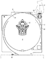
[0033]
FIG. 3 shows the
[0034]
Further, as shown in FIG. 3, the operator can grasp the
[0035]
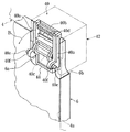
4 and 5 show the
[0036]
On the other hand, the
[0037]
A fixing
[0038]
With the
[0039]
In the present embodiment, since the game
[0040]
Thereafter, when the
[0041]
As shown in FIG. 2, the receiving
[0042]
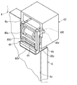
6 and 7 show a process of tightening the
[0043]
As shown in FIG. 7, when the
[0044]
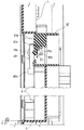
Next, the tightening of the
FIG. 8 specifically shows the relationship between the
[0045]
The receiving
[0046]
Here, the
[0047]
FIG. 9 specifically shows a tightened state of the
[0048]
Further, the pressing force Fv in the pressing down direction can eliminate the gap between the lower end of the
[0049]
The above is the mounting operation of the
[0050]
Thereafter, when the
[0051]
When removing the
[0052]
As is clear from the above description, in the pachinko gaming machine 1 according to the present embodiment, the
[0053]
In the present embodiment, since the
[0054]
The present invention is not limited to the above-described embodiment, but can be suitably implemented in other embodiments. For example, the
[0055]
In one embodiment, the
[0056]
Further, the specific shapes and structures of the
【The invention's effect】
INDUSTRIAL APPLICABILITY The gaming machine of the present invention can perform operations such as handling and attaching / detaching a gaming board in a very rational manner, and can greatly improve the workability. In addition, since the game board can be easily carried and fixed to the base frame, it is possible to simultaneously improve the game performance of the gaming machine in addition to the improvement of the work efficiency.
[Brief description of the drawings]
FIG. 1 is a perspective view of a pachinko gaming machine.
FIG. 2 is a front view of a game board and a base frame (partly).
FIG. 3 is a front view showing the game board alone.
FIG. 4 is a perspective view of a fastener.
FIG. 5 is a sectional view taken along line VV in FIG.
FIG. 6 is a perspective view showing a process of fastening the game board by the fastening tool.
FIG. 7 is a perspective view showing a state in which the fastener is displaced to the folding position from the state of FIG. 6;
FIG. 8 is a diagram showing a tightening process by a fastener using a cross section along the line VIII-VIII in FIG. 2;
FIG. 9 is a sectional view taken along the line VIII-IX in FIG.
[Explanation of symbols]
1 Pachinko machine
4 base frame
6 game board
8 game area
40 fastening tools (fastening means, releasing means)
40b Handle
40e Tightening pin (Tightening part)
42 Receiving seat (tightening means)
42b receiving groove
42c contact part
46 Panel decoration (decoration part)
Claims (1)
前記遊技盤に設けられ、手指を挿入可能な隙間と、
前記遊技盤を前記基枠に締め付ける締付手段と、
を具備したことを特徴とする遊技機。A base frame into which a game board can be fitted,
A gap provided on the game board, into which a finger can be inserted,
Fastening means for fastening the game board to the base frame,
A gaming machine comprising:
Priority Applications (1)
| Application Number | Priority Date | Filing Date | Title |
|---|---|---|---|
| JP2002358981A JP4552043B2 (en) | 2002-12-11 | 2002-12-11 | Game machine |
Applications Claiming Priority (1)
| Application Number | Priority Date | Filing Date | Title |
|---|---|---|---|
| JP2002358981A JP4552043B2 (en) | 2002-12-11 | 2002-12-11 | Game machine |
Publications (3)
| Publication Number | Publication Date |
|---|---|
| JP2004187902A true JP2004187902A (en) | 2004-07-08 |
| JP2004187902A5 JP2004187902A5 (en) | 2006-02-02 |
| JP4552043B2 JP4552043B2 (en) | 2010-09-29 |
Family
ID=32758512
Family Applications (1)
| Application Number | Title | Priority Date | Filing Date |
|---|---|---|---|
| JP2002358981A Expired - Fee Related JP4552043B2 (en) | 2002-12-11 | 2002-12-11 | Game machine |
Country Status (1)
| Country | Link |
|---|---|
| JP (1) | JP4552043B2 (en) |
Cited By (2)
| Publication number | Priority date | Publication date | Assignee | Title |
|---|---|---|---|---|
| JP2007202839A (en) * | 2006-02-02 | 2007-08-16 | Olympia:Kk | Pinball game machine |
| JP2011067402A (en) * | 2009-09-25 | 2011-04-07 | Heiwa Corp | Movable accessory device |
Citations (6)
| Publication number | Priority date | Publication date | Assignee | Title |
|---|---|---|---|---|
| JPH0320227U (en) * | 1989-06-30 | 1991-02-27 | ||
| JPH0539582U (en) * | 1991-10-29 | 1993-05-28 | 株式会社三洋物産 | Fasteners for fixing game boards on pachinko machines |
| JPH0623115A (en) * | 1992-07-06 | 1994-02-01 | Adachi Raito Kogyosho Kk | Mechanism plate for pachinko ball machine |
| JPH09262354A (en) * | 1996-03-29 | 1997-10-07 | Newgin Kk | Play panel attachable and detachable exchange type pachinko game machine |
| JPH11103990A (en) * | 1997-10-06 | 1999-04-20 | Kazunari Iwasaki | Bouquet preparing device of disassembling type |
| JP2002349149A (en) * | 2001-05-22 | 2002-12-04 | Shigeru Taguchi | Switchable aluminum-sash sliding doors |
-
2002
- 2002-12-11 JP JP2002358981A patent/JP4552043B2/en not_active Expired - Fee Related
Patent Citations (6)
| Publication number | Priority date | Publication date | Assignee | Title |
|---|---|---|---|---|
| JPH0320227U (en) * | 1989-06-30 | 1991-02-27 | ||
| JPH0539582U (en) * | 1991-10-29 | 1993-05-28 | 株式会社三洋物産 | Fasteners for fixing game boards on pachinko machines |
| JPH0623115A (en) * | 1992-07-06 | 1994-02-01 | Adachi Raito Kogyosho Kk | Mechanism plate for pachinko ball machine |
| JPH09262354A (en) * | 1996-03-29 | 1997-10-07 | Newgin Kk | Play panel attachable and detachable exchange type pachinko game machine |
| JPH11103990A (en) * | 1997-10-06 | 1999-04-20 | Kazunari Iwasaki | Bouquet preparing device of disassembling type |
| JP2002349149A (en) * | 2001-05-22 | 2002-12-04 | Shigeru Taguchi | Switchable aluminum-sash sliding doors |
Cited By (2)
| Publication number | Priority date | Publication date | Assignee | Title |
|---|---|---|---|---|
| JP2007202839A (en) * | 2006-02-02 | 2007-08-16 | Olympia:Kk | Pinball game machine |
| JP2011067402A (en) * | 2009-09-25 | 2011-04-07 | Heiwa Corp | Movable accessory device |
Also Published As
| Publication number | Publication date |
|---|---|
| JP4552043B2 (en) | 2010-09-29 |
Similar Documents
| Publication | Publication Date | Title |
|---|---|---|
| JP3248712B2 (en) | Function expansion device for information processing device | |
| EP1408800B1 (en) | Article support device | |
| JP4470369B2 (en) | Game machine | |
| JP4058456B2 (en) | Function expansion device for information processing device | |
| JP2004187902A (en) | Game machine | |
| WO2012140767A1 (en) | Display device | |
| CN210653262U (en) | Baby carriage push handle assembly structure | |
| JP4160761B2 (en) | Fitting | |
| JP2004160158A (en) | Game machine and its assembling method | |
| JP3039541U (en) | Multi-functional cutter knife with easy blade attachment and detachment | |
| JPH06283149A (en) | Clamp structure for battery pack | |
| JP2003325916A5 (en) | ||
| JP3412515B2 (en) | Iron storage case | |
| JP3706106B2 (en) | Function expansion device for information processing apparatus and information processing system | |
| JP3089004U (en) | AV equipment that can be operated by remote control | |
| CN221546688U (en) | Door handle assembly | |
| JP3760410B2 (en) | Cake sorting equipment | |
| JP2984821B2 (en) | Pachinko machine with removable game board | |
| JP3867824B2 (en) | Button locking jig | |
| TWI766083B (en) | Fixtures | |
| JPH09306451A (en) | Information processing device | |
| JP2013124065A (en) | Skin member of vehicular seat | |
| JP2004068394A (en) | Lock of attache case | |
| JP3079143U (en) | Detachable handle structure | |
| JP2025125162A (en) | Transfer jig |
Legal Events
| Date | Code | Title | Description |
|---|---|---|---|
| A521 | Written amendment |
Free format text: JAPANESE INTERMEDIATE CODE: A523 Effective date: 20051209 |
|
| A621 | Written request for application examination |
Free format text: JAPANESE INTERMEDIATE CODE: A621 Effective date: 20051209 |
|
| RD04 | Notification of resignation of power of attorney |
Free format text: JAPANESE INTERMEDIATE CODE: A7424 Effective date: 20071221 |
|
| A131 | Notification of reasons for refusal |
Free format text: JAPANESE INTERMEDIATE CODE: A131 Effective date: 20090924 |
|
| A521 | Written amendment |
Free format text: JAPANESE INTERMEDIATE CODE: A523 Effective date: 20091124 |
|
| RD02 | Notification of acceptance of power of attorney |
Free format text: JAPANESE INTERMEDIATE CODE: A7422 Effective date: 20091124 |
|
| A521 | Written amendment |
Free format text: JAPANESE INTERMEDIATE CODE: A821 Effective date: 20091126 |
|
| A131 | Notification of reasons for refusal |
Free format text: JAPANESE INTERMEDIATE CODE: A131 Effective date: 20100217 |
|
| A521 | Written amendment |
Free format text: JAPANESE INTERMEDIATE CODE: A523 Effective date: 20100419 |
|
| TRDD | Decision of grant or rejection written | ||
| A01 | Written decision to grant a patent or to grant a registration (utility model) |
Free format text: JAPANESE INTERMEDIATE CODE: A01 Effective date: 20100531 |
|
| A01 | Written decision to grant a patent or to grant a registration (utility model) |
Free format text: JAPANESE INTERMEDIATE CODE: A01 |
|
| A61 | First payment of annual fees (during grant procedure) |
Free format text: JAPANESE INTERMEDIATE CODE: A61 Effective date: 20100623 |
|
| FPAY | Renewal fee payment (event date is renewal date of database) |
Free format text: PAYMENT UNTIL: 20130723 Year of fee payment: 3 |
|
| R150 | Certificate of patent or registration of utility model |
Ref document number: 4552043 Country of ref document: JP Free format text: JAPANESE INTERMEDIATE CODE: R150 Free format text: JAPANESE INTERMEDIATE CODE: R150 |
|
| R250 | Receipt of annual fees |
Free format text: JAPANESE INTERMEDIATE CODE: R250 |
|
| R250 | Receipt of annual fees |
Free format text: JAPANESE INTERMEDIATE CODE: R250 |
|
| R250 | Receipt of annual fees |
Free format text: JAPANESE INTERMEDIATE CODE: R250 |
|
| R250 | Receipt of annual fees |
Free format text: JAPANESE INTERMEDIATE CODE: R250 |
|
| R250 | Receipt of annual fees |
Free format text: JAPANESE INTERMEDIATE CODE: R250 |
|
| LAPS | Cancellation because of no payment of annual fees |