JP2004190810A - Mounting structure of energy absorption (ea) material and locking piece - Google Patents
Mounting structure of energy absorption (ea) material and locking piece Download PDFInfo
- Publication number
- JP2004190810A JP2004190810A JP2002361070A JP2002361070A JP2004190810A JP 2004190810 A JP2004190810 A JP 2004190810A JP 2002361070 A JP2002361070 A JP 2002361070A JP 2002361070 A JP2002361070 A JP 2002361070A JP 2004190810 A JP2004190810 A JP 2004190810A
- Authority
- JP
- Japan
- Prior art keywords
- locking piece
- mounting structure
- projection
- opening
- surrounding wall
- Prior art date
- Legal status (The legal status is an assumption and is not a legal conclusion. Google has not performed a legal analysis and makes no representation as to the accuracy of the status listed.)
- Pending
Links
- 239000000463 material Substances 0.000 title claims abstract description 109
- 238000010521 absorption reaction Methods 0.000 title description 4
- 229920003002 synthetic resin Polymers 0.000 claims abstract description 13
- 239000000057 synthetic resin Substances 0.000 claims abstract description 13
- JOYRKODLDBILNP-UHFFFAOYSA-N Ethyl urethane Chemical compound CCOC(N)=O JOYRKODLDBILNP-UHFFFAOYSA-N 0.000 claims abstract description 9
- 239000006260 foam Substances 0.000 claims abstract description 6
- 210000000078 claw Anatomy 0.000 claims description 22
- 230000000149 penetrating effect Effects 0.000 claims 1
- 235000019589 hardness Nutrition 0.000 abstract 1
- 230000002093 peripheral effect Effects 0.000 description 8
- 238000004519 manufacturing process Methods 0.000 description 5
- 238000000465 moulding Methods 0.000 description 3
- 238000000926 separation method Methods 0.000 description 3
- 238000010586 diagram Methods 0.000 description 2
- 238000000034 method Methods 0.000 description 2
- 230000035939 shock Effects 0.000 description 2
- 239000011358 absorbing material Substances 0.000 description 1
- 238000013459 approach Methods 0.000 description 1
- 238000005452 bending Methods 0.000 description 1
- 239000000470 constituent Substances 0.000 description 1
- 230000000694 effects Effects 0.000 description 1
- 238000010097 foam moulding Methods 0.000 description 1
- 238000002347 injection Methods 0.000 description 1
- 239000007924 injection Substances 0.000 description 1
- 239000011550 stock solution Substances 0.000 description 1
Images


Landscapes
- Vibration Dampers (AREA)
- Connection Of Plates (AREA)
- Insertion Pins And Rivets (AREA)
Abstract
Description
【0001】
【発明の属する技術分野】
本発明はEA材(衝撃エネルギー吸収材)の取付構造に係り、特に自動車のトリムに適用するのに好適なEA材の取付構造に関する。また、本発明は、このEA材の取付構造に用いられる係止ピースに関する。
【0002】
【従来の技術】
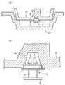
自動車のドアトリムには、側面衝突(側突)時の衝撃エネルギー吸収(Energy Absorption:EA)のために、硬質ウレタンフォームよりなるEA材を取り付けている。このドアトリムに対し、硬質ウレタンフォーム製EA材を取り付ける方法として、特開2001−322507号には、図3,4に示す構造が記載されている。図3は同号公報の図7に記載されたEA材の取付構造を示す断面図、図4(a)はこの構造に用いられている筒状体20の斜視図、図4(b)はこの筒状体20の断面斜視図である。
【0003】
この筒状体20は筒部21及び張出部22を一体に備えている。この筒部21の先端からは内向きに爪部23が設けられている。トリム31から突設されたロッド26の外周面に凹部27が周設されており、爪部23が該凹部27に係合している。
【0004】
なお、筒部21には先端から筒部21の軸心線と平行方向にスリット24が延設されており、筒部21はその拡径方向に弾性的に変形可能となっている。
【0005】
EA材33をトリム31に取り付けるには、EA材33の取付孔34にロッド26が挿入されるようにEA材33をトリム31の面に沿わせ、次いで筒状体20をロッド26に嵌合させて押し込み、爪部23を凹部27に係合させる。これにより、張出部22はEA材33の取付孔34の周縁部を押さえつける。
【0006】
なお、この筒部21は先細形のテーパ形状となっており、取付孔34に挿入し易いものとなっている。筒状体20をロッド26に装着した状態にあっては、筒部21の外周面が取付孔34の内周面に密着している。
【0007】
【特許文献1】
特開2001−322507号公報
【0008】
【発明が解決しようとする課題】
上記従来のEA材の取付構造にあっては、EA材をトリム31に取り付けるに際しては、EA材をトリム31に当てがう作業と、その後ロッド26に筒状体20を嵌着させる作業との2作業工程が必要となり、作業に手間がかかる。本発明は、EA材のトリム等の部材への取り付け作業性が著しく改善されたEA材の取付構造と、そのための係止ピースとを提供することを目的とする。
【0009】
【課題を解決するための手段】
本発明のEA材の取付構造は、部材にEA材を取り付けた構造において、該EA材に一体に設けられた係止ピースの突起が前記部材に設けられた被係止部に係合することにより、該EA材が該部材に取り付けられており、該突起の基端側が囲壁によって囲まれていることを特徴とするものである。
【0010】
かかるEA材の取付構造にあっては、係止ピースがEA材と一体化されているので、この係止ピース付きのEA材を部材に当てがいながら、該係止ピースの突起を部材の被係止部に係合させるという1作業工程にてEA材を部材に取り付けることができる。また、突起の基端側が囲壁で囲まれているので、EA材の製造時に突起の基端側にEA材の構成材料(例えば、発泡合成樹脂)が入り込むことを防止できる。
【0011】
本発明では、突起は弾性変形可能であり、前記被係止部に係合されるに際し弾性変形した後、弾性的に復元することにより該被係止部に係合している構成とすることにより、突起を被係止部に対し容易に取り付けることができる。
【0012】
本発明では、この被係止部は開口であることが好ましい。このように開口よりなる被係止部は、所望位置に容易に設けることができる。この場合、係止ピースの突起は該開口の縁部に係合した爪部を有することが好ましい。特に、該突起の突出方向の側面に爪部が設けられていることが好ましく、この突起が開口の縁部に沿って複数個設けられていることが好ましい。
【0013】
かかるEA材の取付構造であれば、突起を開口に差し込みながらEA材を部材に当てがうことにより部材へのEA材の取り付けを行うことができる。また、突起が開口の縁部に沿って複数個設けられることにより、EA材の部材面に沿う方向の動き(ガタツキ)が防止される。
【0014】
本発明では、係止ピースはフランジを有しており、前記突起及び囲壁は該フランジから突設されており、該囲壁の先端と爪部との間で開口の縁部が挟持されていることが好ましい。このように構成することにより、EA材の部材接離方向への動き(ガタツキ)が防止される。
【0015】
本発明では、係止ピースの基部がEA材に埋設されていることにより、係止ピースとEA材との結合強度を高めることができる。また、係止ピースの基部がEA材を貫通しないように設けることにより、係止ピース近傍におけるEA材の衝撃吸収特性を高めることができる。
【0016】
本発明では、EA材は合成樹脂特に硬質ウレタンフォーム等の発泡合成樹脂製であることが好ましい。この合成樹脂製EA材に対しては、係止ピースを、その基部を埋設させることにより強固に一体化させることができる。
【0017】
この合成樹脂製のEA材を製造する場合、EA材成形用の金型に、該係止ピースの囲壁を嵌合させて保持させておくことにより、成形を効率良く行うことができる。また、この囲壁が金型に密着し、囲壁の内側にウレタン等が入り込むことが防止され、バリの発生が防止される。
【0018】
このEA材の取付構造は、自動車キャビンの内面に沿って配置される頭部保護パッドやピラーパッドの取り付けに好適であるが、これに限定されるものではない。
【0019】
本発明(請求項13)の係止ピースは、EA材中に埋設される基部と、該基部の一端側に設けられたフランジと、該フランジから突設された、弾性変形可能であり、EA材取付用開口に挿入される複数の突起と、該突起の側面に設けられており、該開口の端部に係合可能な爪部と、該フランジから該突起と同方向に突設されており、該突起の基端側を取り巻いている囲壁と、を備えてなるものである。この係止ピースは、上記EA材の取付構造に好適である。
【0020】
【発明の実施の形態】
以下、図面を参照して実施の形態について説明する。図1(a)は実施の形態に係るEA材の取付構造を示す略水平方向の断面図、図1(b),(c)はこのEA材の取付構造に用いられている係止ピースの縦断面図と斜視図、図2(a)は係止ピース付きEA材の製造方法を説明する断面図、図2(b)は図2(a)の一部の拡大図である。
【0021】
図1の通り、硬質ウレタンフォーム等の合成樹脂よりなる板状のEA材1が部材としてのトリム(この実施の形態ではドアトリム)2に対し係止ピース3を介して取り付けられている。この実施の形態では、被係止部として開口4が該トリム2に設けられており、係止ピース3は該開口4に係合している。この開口4は円形であることが好ましいが、必ずしもこれに限定されるものではない。
【0022】
この係止ピース3は、筒部6と、該筒部6の後端から外向き鍔状に張り出すアンカー5と、筒部6の先端から外向き鍔状に張り出すフランジ7と、筒部6の先端面から該筒部6の筒軸方向と平行方向に突設された複数(この実施の形態では2個)の突起8と、この突起8,8よりなる突起群の外側を取り巻くように該フランジ7から突起8と同方向に突設された囲壁9とを有する。この突起8は開口4の周方向に間隔をおいて複数個(この実施の形態では4個)設けられている。なお、突起8の数は、2〜4個程度が実用的である。
【0023】
この突起8の突出方向の側面には、側方に張り出すように爪部8aが設けられている。この爪部8aは、フランジ7に接近するほど側方への張り出し高さが大きくなっており、突起8の外側の側面は先細状のテーパ面となっている。これにより、突起8は開口4に容易に挿入可能である。
【0024】
囲壁9は円環状である。囲壁9の高さは、フランジ7から爪部8aの下端までの距離よりも小さい。これにより、爪部8aとフランジ7との間にスペースSが存在している。
【0025】
この係止ピース3は、合成樹脂により全体として一体に成形されており、突起8は求心方向に弾性的に変形可能となっている。
【0026】
図1の通り、係止ピース3は、その筒部6及びアンカー5がEA材1中に埋設されている。フランジ7は、この実施の形態では、その囲壁9よりも外周側の上面がEA材1の表面に露呈しているが、この部分はEA材中に埋設されてもよい。ただし、いずれの場合でも、囲壁9の上端側は、EA材1の板面と面一かそれよりも突出している。この囲壁9の上端と爪部8aとでトリム2の開口4の縁部を狭持することにより、EA材1とトリム2との接離方向の位置関係が一義的に定まったものとなる。
【0027】
この係止ピース3は、図1では1個のみ図示されているが、EA材1の大きさや形状に応じ2個以上設けられてもよい。係止ピース3の位置もEA材1の大きさや形状に応じて選定される。
【0028】
この係止ピース3付きのEA材1は、突起8を開口4に差し込みながらトリム2に当てがうことにより該トリム2に取り付けられる。EA材1をトリム2に押し付けると、突起8が開口4に押し込まれる。爪部8aが開口4の内周面に押し付けられることにより、該突起8が接近方向に撓みながら開口4に差し込まれる。そして、爪部8aが開口4を通り抜けると、突起8が弾性的に元の形状に復帰し、各突起8の側面が開口4の内周面に弾性的に押し付けられると共に、爪部8aと囲壁9とで、スペースSに入り込んだ開口4の縁部を挟持する。このように、係止ピース3付きのEA材1をトリム2に重ねるという1作業工程のみでEA材1をトリム2に取り付けることができ、取付作業効率が著しく向上する。また、係止ピース3の各突起8の側面が開口4の内周面に弾性的に当接すると共に、各突起8の爪部8aと囲壁9の上端との間で開口4の縁部を挟持しているので、EA材1がトリム2の面方向及び接離方向のいずれにも不動であり、EA材1の取付がきわめてしっかりしたものとなる。
【0029】
図1(a)の通り、係止ピース3は、その筒部6及びアンカー5がEA材1中に埋設され、且つこの筒部6及びアンカー5はEA材1の厚み方向の半分程度(例えば30〜50%)の範囲にのみ存在している。このように係止ピース3がEA材1を貫通しておらず、係止ピース3付近においてもEA材1が十分な厚みを有しているところから、この係止ピース3付近においてもEA材1の衝撃吸収特性が良好である。
【0030】
このEA材1の取付構造にあっては、係止ピース3及び開口4の配置や個数は任意であり、種々様々な形状のEA材であってもトリムに対ししっかりとしかも容易に取り付けることができる。また、EA材が軟質であっても、係止ピース3及び開口4の数を多くすることにより、EA材をしっかりと留め付けることができる。
【0031】
この係止ピース3付きEA材1を製造するには、図2のように下金型10及び上金型11よりなる金型を用い、この上金型11のキャビティ面に係止ピース3を保持させておき、キャビティ内に合成樹脂材料を供給して成形すればよい。ウレタン等の場合であれば、下金型10内にウレタン等の原液を供給し、これを発泡させればよい。なお、射出発泡成形としてもよい。
【0032】
係止ピース3を保持する上金型11には、該係止ピース3の突起8を受け入れる凹部12が設けられている。また、この凹部12の入口部分には、囲壁13がきつく嵌合する円環形の段部13が設けられている。囲壁9を該段部13に緊嵌させることにより、係止ピース3を上型11に保持させておくことができる。なお、この実施の形態では、囲壁9を段部13に嵌合させたときに、図2(b)の通り、フランジ7の該囲壁9よりも外側領域が上型11の下面に密着する。これにより、係止ピース3が傾いたりすることなく、しっかりと上型11に保持される。
【0033】
このように、上型11に係止ピース1を保持させて上記の成形を行う。金型内で合成樹脂が所定程度硬化した後、成形品を脱型することにより、係止ピース3付きのEA材1が得られる。
【0034】
なお、囲壁9が段部13にきつく嵌まり、しかもフランジ7が上型11の下面に密着しているので、囲壁9の上端面や囲壁9の内側に合成樹脂が入り込むことが防止され、バリが発生することが防止される。
【0035】
上記実施の形態は本発明の一例であり、本発明は図示以外の形態をもとりうる。例えば、フランジ7やアンカー5は図示以外の形状とされてもよい。
【0036】
【発明の効果】
以上の通り、本発明によると、EA材をトリム等の部材に対し容易に取り付けることが可能となる。本発明によると、EA材による衝撃吸収特性を向上させたり、種々の形状、大きさ、硬度のEA材であっても部材に対ししっかりと取り付けたりすることも可能となる。
【図面の簡単な説明】
【図1】図1(a)は実施の形態に係るEA材の取付構造を示す断面図、図1(b)はこのEA材の取付構造の係止ピースの縦断面図、図1(c)はこの係止ピースの斜視図である。
【図2】図2(a)は係止ピース付きEA材の製造方法を説明する断面図、図2(b)は図2(a)の一部の拡大図である。
【図3】従来例を示す断面図である。
【図4】図3の構造の説明図である。
【符号の説明】
1 EA材
2 トリム
3 係止ピース
4 開口
5 アンカー
6 筒部
7 フランジ
8 突起
8a 爪部
9 囲壁
10 下金型
11 上金型
12 凹部
13 段部[0001]
TECHNICAL FIELD OF THE INVENTION
The present invention relates to a mounting structure of an EA material (impact energy absorbing material), and more particularly to a mounting structure of an EA material suitable for application to an automobile trim. The present invention also relates to a locking piece used for the EA material mounting structure.
[0002]
[Prior art]
An EA material made of rigid urethane foam is attached to a door trim of an automobile to absorb impact energy (EA) in a side collision (side collision). As a method of attaching a hard urethane foam EA material to the door trim, JP-A-2001-322507 describes a structure shown in FIGS. FIG. 3 is a cross-sectional view showing the mounting structure of the EA material described in FIG. 7 of the same publication, FIG. 4 (a) is a perspective view of a tubular body 20 used in this structure, and FIG. FIG. 3 is a sectional perspective view of the tubular body 20.
[0003]
The tubular body 20 has a
[0004]
In addition, a
[0005]
To attach the
[0006]
The
[0007]
[Patent Document 1]
JP 2001-322507 A
[Problems to be solved by the invention]
In the above-described conventional EA material mounting structure, when attaching the EA material to the trim 31, the work of applying the EA material to the trim 31 and the work of subsequently fitting the tubular body 20 to the rod 26 are performed. Two work processes are required, and work is troublesome. SUMMARY OF THE INVENTION It is an object of the present invention to provide a mounting structure of an EA material in which the workability of mounting the EA material to a member such as a trim is significantly improved, and a locking piece therefor.
[0009]
[Means for Solving the Problems]
In the EA material mounting structure of the present invention, in the structure in which the EA material is mounted on the member, the projection of the locking piece provided integrally with the EA material is engaged with the locked portion provided on the member. Thus, the EA material is attached to the member, and the base end side of the projection is surrounded by the surrounding wall.
[0010]
In such an EA material mounting structure, since the locking piece is integrated with the EA material, the EA material with the locking piece is applied to the member while the projection of the locking piece is attached to the member. The EA material can be attached to the member in one operation step of engaging with the locking portion. Further, since the base end side of the projection is surrounded by the surrounding wall, it is possible to prevent a constituent material (for example, a foamed synthetic resin) of the EA material from entering the base end side of the projection during the production of the EA material.
[0011]
In the present invention, the protrusion is elastically deformable, and after being elastically deformed when being engaged with the locked portion, is elastically restored to engage with the locked portion. Thereby, the projection can be easily attached to the locked portion.
[0012]
In the present invention, the locked portion is preferably an opening. The locked portion having the opening as described above can be easily provided at a desired position. In this case, it is preferable that the projection of the locking piece has a claw engaged with the edge of the opening. In particular, it is preferable that a claw portion is provided on a side surface of the protrusion in the protruding direction, and it is preferable that a plurality of protrusions be provided along the edge of the opening.
[0013]
With such an attachment structure of the EA material, the EA material can be attached to the member by applying the EA material to the member while inserting the projection into the opening. In addition, since a plurality of protrusions are provided along the edge of the opening, movement (rattle) in the direction along the member surface of the EA material is prevented.
[0014]
In the present invention, the locking piece has a flange, the protrusion and the surrounding wall are provided so as to protrude from the flange, and the edge of the opening is sandwiched between the tip of the surrounding wall and the claw portion. Is preferred. With this configuration, the movement (rattle) of the EA material in the member contact / separation direction is prevented.
[0015]
In the present invention, since the base of the locking piece is embedded in the EA material, the bonding strength between the locking piece and the EA material can be increased. Further, by providing the base of the locking piece so as not to penetrate the EA material, it is possible to enhance the impact absorption characteristics of the EA material in the vicinity of the locking piece.
[0016]
In the present invention, the EA material is preferably made of a synthetic resin, particularly a foamed synthetic resin such as rigid urethane foam. The locking piece can be firmly integrated with the synthetic resin EA material by embedding its base.
[0017]
In the case of manufacturing this synthetic resin EA material, the molding can be performed efficiently by fitting and holding the surrounding wall of the locking piece in the EA material molding die. Further, the surrounding wall is in close contact with the mold, so that urethane or the like is prevented from entering the inside of the surrounding wall, and the occurrence of burrs is prevented.
[0018]
The mounting structure of the EA material is suitable for mounting a head protection pad or a pillar pad arranged along the inner surface of the automobile cabin, but is not limited thereto.
[0019]
The locking piece of the present invention (claim 13) has a base buried in the EA material, a flange provided on one end side of the base, and is elastically deformable and protruded from the flange. A plurality of projections to be inserted into the material mounting opening, a claw provided on a side surface of the projection, and engageable with an end of the opening, and a projection protruding from the flange in the same direction as the projection. And a surrounding wall surrounding the base end side of the projection. This locking piece is suitable for the mounting structure of the EA material.
[0020]
BEST MODE FOR CARRYING OUT THE INVENTION
Hereinafter, embodiments will be described with reference to the drawings. FIG. 1A is a substantially horizontal sectional view showing an attachment structure of an EA material according to the embodiment, and FIGS. 1B and 1C are diagrams of a locking piece used in the attachment structure of the EA material. FIG. 2 (a) is a longitudinal sectional view and a perspective view, FIG. 2 (a) is a sectional view for explaining a method of manufacturing an EA material with a locking piece, and FIG. 2 (b) is an enlarged view of a part of FIG. 2 (a).
[0021]
As shown in FIG. 1, a plate-
[0022]
The
[0023]
A
[0024]
The surrounding
[0025]
The
[0026]
As shown in FIG. 1, the
[0027]
Although only one
[0028]
The
[0029]
As shown in FIG. 1A, the
[0030]
In the mounting structure of the
[0031]
In order to manufacture the
[0032]
The upper mold 11 holding the
[0033]
In this manner, the above-described molding is performed by holding the
[0034]
In addition, since the surrounding
[0035]
The above embodiment is an example of the present invention, and the present invention can take forms other than those illustrated. For example, the
[0036]
【The invention's effect】
As described above, according to the present invention, the EA material can be easily attached to a member such as a trim. ADVANTAGE OF THE INVENTION According to this invention, it becomes possible to improve the shock absorption characteristic by an EA material, and to attach it firmly to a member even if it is an EA material of various shapes, sizes, and hardness.
[Brief description of the drawings]
FIG. 1A is a cross-sectional view showing an EA material mounting structure according to an embodiment, FIG. 1B is a longitudinal sectional view of a locking piece of the EA material mounting structure, and FIG. () Is a perspective view of this locking piece.
FIG. 2A is a cross-sectional view for explaining a method of manufacturing an EA material with a locking piece, and FIG. 2B is an enlarged view of a part of FIG. 2A.
FIG. 3 is a sectional view showing a conventional example.
FIG. 4 is an explanatory diagram of the structure of FIG. 3;
[Explanation of symbols]
DESCRIPTION OF
Claims (15)
該EA材に一体に設けられた係止ピースの突起が前記部材に設けられた被係止部に係合することにより、該EA材が該部材に取り付けられており、
該突起の基端側が囲壁によって囲まれていることを特徴とするEA材の取付構造。In the structure where the EA material is attached to the member,
The EA material is attached to the member by engaging a projection of a locking piece provided integrally with the EA material with a locked portion provided on the member,
A mounting structure for an EA material, wherein a base end side of the projection is surrounded by a surrounding wall.
該基部の一端側に設けられたフランジと、
該フランジから突設された、弾性変形可能であり、EA材取付用開口に挿入される複数の突起と、
該突起の側面に設けられており、該開口の端部に係合可能な爪部と、
該フランジから該突起と同方向に突設されており、該突起の基端側を取り巻いている囲壁と、
を備えてなるEA材取付用係止ピース。A base buried in the EA material;
A flange provided on one end side of the base,
A plurality of projections projecting from the flange, which are elastically deformable and are inserted into the EA material mounting opening;
A claw portion provided on a side surface of the projection and engageable with an end of the opening;
An enclosing wall projecting from the flange in the same direction as the projection, and surrounding a base end side of the projection;
A locking piece for mounting an EA material, comprising:
Priority Applications (6)
| Application Number | Priority Date | Filing Date | Title |
|---|---|---|---|
| JP2002361070A JP2004190810A (en) | 2002-12-12 | 2002-12-12 | Mounting structure of energy absorption (ea) material and locking piece |
| US10/530,324 US7547061B2 (en) | 2002-10-10 | 2003-10-06 | Attachment structure of EA component |
| EP03748716.2A EP1550818B1 (en) | 2002-10-10 | 2003-10-06 | Ea member attaching construction |
| AU2003268767A AU2003268767A1 (en) | 2002-10-10 | 2003-10-06 | Ea member attaching construction |
| PCT/JP2003/012765 WO2004033930A1 (en) | 2002-10-10 | 2003-10-06 | Ea member attaching construction |
| CA002501410A CA2501410A1 (en) | 2002-10-10 | 2003-10-06 | Attachment structure of ea component |
Applications Claiming Priority (1)
| Application Number | Priority Date | Filing Date | Title |
|---|---|---|---|
| JP2002361070A JP2004190810A (en) | 2002-12-12 | 2002-12-12 | Mounting structure of energy absorption (ea) material and locking piece |
Publications (1)
| Publication Number | Publication Date |
|---|---|
| JP2004190810A true JP2004190810A (en) | 2004-07-08 |
Family
ID=32759954
Family Applications (1)
| Application Number | Title | Priority Date | Filing Date |
|---|---|---|---|
| JP2002361070A Pending JP2004190810A (en) | 2002-10-10 | 2002-12-12 | Mounting structure of energy absorption (ea) material and locking piece |
Country Status (1)
| Country | Link |
|---|---|
| JP (1) | JP2004190810A (en) |
Cited By (2)
| Publication number | Priority date | Publication date | Assignee | Title |
|---|---|---|---|---|
| JP2012062954A (en) * | 2010-09-15 | 2012-03-29 | Tochigiya Co Ltd | Stopper |
| WO2014042157A1 (en) * | 2012-09-11 | 2014-03-20 | 東海ゴム工業株式会社 | Engine cover |
-
2002
- 2002-12-12 JP JP2002361070A patent/JP2004190810A/en active Pending
Cited By (7)
| Publication number | Priority date | Publication date | Assignee | Title |
|---|---|---|---|---|
| JP2012062954A (en) * | 2010-09-15 | 2012-03-29 | Tochigiya Co Ltd | Stopper |
| WO2014042157A1 (en) * | 2012-09-11 | 2014-03-20 | 東海ゴム工業株式会社 | Engine cover |
| JP2014055529A (en) * | 2012-09-11 | 2014-03-27 | Tokai Rubber Ind Ltd | Engine cover |
| CN104169541A (en) * | 2012-09-11 | 2014-11-26 | 东海橡塑工业株式会社 | engine cover |
| EP2896805A4 (en) * | 2012-09-11 | 2016-05-25 | Sumitomo Riko Co Ltd | MOTOR COVER |
| CN104169541B (en) * | 2012-09-11 | 2017-10-03 | 住友理工株式会社 | engine cover |
| US9816460B2 (en) | 2012-09-11 | 2017-11-14 | Sumitomo Riko Company Limited | Engine cover |
Similar Documents
| Publication | Publication Date | Title |
|---|---|---|
| US7547061B2 (en) | Attachment structure of EA component | |
| JP4692482B2 (en) | EA material mounting structure | |
| JP4379415B2 (en) | EA material mounting structure | |
| JPWO2009019938A1 (en) | EA material | |
| JP2004190810A (en) | Mounting structure of energy absorption (ea) material and locking piece | |
| JP4300996B2 (en) | Method for producing impact energy absorbing material | |
| JP2005047225A (en) | Mold insert holding structure, foam molding method, EA material mounting clip and EA material | |
| JP2004150629A (en) | Ea material mounting structure | |
| JP2004132462A (en) | Mounting structure for ea material | |
| JP2006022898A (en) | Ea material and its mounting structure | |
| JP2005207524A (en) | Clip for mounting ea material and its mounting structure | |
| JP4296884B2 (en) | EA material mounting structure | |
| JP5267547B2 (en) | Clip holding structure for mounting impact energy absorber and mold for mounting shock energy absorber and clip for mounting impact energy absorber | |
| JP4581350B2 (en) | Impact energy absorber and its mounting structure | |
| JP5881281B2 (en) | Foam molded body mounting member, foam molded member, foam molded member manufacturing method, and foam molded member mounting structure | |
| JP4433884B2 (en) | EA material mounting structure | |
| JP2006021614A (en) | Mounting structure of energy absorptin material | |
| JP5691287B2 (en) | Foam molded member, clip for mounting the foam, method for manufacturing foam molded member, and mounting structure for foam molded member | |
| JP2006022877A (en) | Ea material, its setting clip and setting structure | |
| WO2010004920A1 (en) | Ea material | |
| JP2005016682A (en) | Ea material, and manufacturing method and attachment structure for this ea material | |
| JP5644245B2 (en) | Foam molded member, clip for mounting the foam, method for manufacturing foam molded member, and mounting structure for foam molded member | |
| JP2004132463A (en) | Mounting structure for ea material | |
| JP5547033B2 (en) | EA material mounting clip and EA material | |
| JP5605070B2 (en) | Foam molded member, clip for mounting the foam, method for manufacturing foam molded member, and mounting structure for foam molded member |