JP2004190813A - Wire bundle clamp - Google Patents
Wire bundle clamp Download PDFInfo
- Publication number
- JP2004190813A JP2004190813A JP2002361378A JP2002361378A JP2004190813A JP 2004190813 A JP2004190813 A JP 2004190813A JP 2002361378 A JP2002361378 A JP 2002361378A JP 2002361378 A JP2002361378 A JP 2002361378A JP 2004190813 A JP2004190813 A JP 2004190813A
- Authority
- JP
- Japan
- Prior art keywords
- wire bundle
- clamp
- mounting
- leg
- mounting hole
- Prior art date
- Legal status (The legal status is an assumption and is not a legal conclusion. Google has not performed a legal analysis and makes no representation as to the accuracy of the status listed.)
- Withdrawn
Links
Images

Landscapes
- Connection Of Plates (AREA)
- Snaps, Bayonet Connections, Set Pins, And Snap Rings (AREA)
- Insertion, Bundling And Securing Of Wires For Electric Apparatuses (AREA)
- Installation Of Indoor Wiring (AREA)
Abstract
Description
【0001】
【発明の属する技術分野】
本発明は、電線束を板状の取り付け対象物に固定するための電線束用クランプに関し、特に、取り付け面(表面)側の操作だけで、取り付け対象物から取り外すことが可能な電線束用クランプに関する。
【0002】
【従来の技術】
取り付け面(表面)側の操作だけで、取り付け対象物から取り外すことが可能な電線束用クランプに関して、本体を板材側へ押し付けて当接部を弾性変形させながら連結部を取り付け穴の奥へと押しこみ、本体を板材の表裏面と平行な方向へ変位させると、挟持部が板材の裏面に引っかかる位置へと変位し、また、第1突起部及び第2突起部は、双方とも板材に形成された位置決め穴に嵌まり込む技術が提案されている(例えば、特許文献1参照)。
【特許文献1】特開2002−164673公報
【0003】
【発明が解決しようとする課題】
取り付け面の裏側に手をまわさなくても、取り付け面側における操作だけで取り付け対象物から取り外すことができるクランプは、上述した特開2002−164673公報に提案されているが、少なくとも、取り付け対象物に3個所の穴が必要であり、1方向にしかクランプを取り付けることができない。クランプを任意の方向に取り付ける場合には、それぞれの方向に対して穴位置を設定しなければならない。
本発明は、取り付け対象物の1つの取り付け穴に方向規制なく固定でき、かつ取り付け面側からの操作で取り付け対象物から取り外すことができる電線束用クランプを提供することを目的とする。
【0004】
【課題を解決するための手段】
上記目的を達成するために、請求項1記載の発明は、電線束を取り付け対象物に固定するための電線束用クランプにおいて、電線束を収容する本体と、本体底面に設けられ取り付け対象物の取り付け穴に遊嵌される保持脚と、保持脚から斜め下方に延びる弾性変形可能な支持脚とを備えた電線束用クランプを最も主要な特徴とする。
請求項2記載の発明は、請求項1記載の電線束用クランプにおいて、保持脚は、取り付け対象物の肉厚分の嵌合部を有し、嵌合部が取り付け穴の縁に嵌合された状態で、取り付け穴の対向する端縁に先端が係合するように支持脚が構成されている電線束用クランプを主要な特徴とする。
請求項3記載の発明は、請求項2記載の電線束用クランプにおいて、支持脚先端に固定鍔を形成した電線束用クランプを主要な特徴とする。
【0005】
【発明の実施の形態】
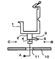
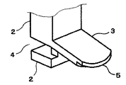
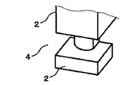
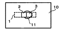
以下、本発明の実施の形態を図面に従って説明する。図1は本発明の実施の形態に係る電線束用クランプが取り付け対象物に取り付けられる前の状態を示す図、図2は図1のB方向から見た電線束用クランプの斜視図、図3は図1のC方向から見た電線束用クランプの斜視図、図4は本発明の実施の形態に係る電線束用クランプが取り付け対象物に取り付けられ、電線束を収容した状態を示す図、図5は図4の底面図である。
本実施の形態の電線束用クランプは合成樹脂でできており、電線束を収容する本体1と、本体1底面に設けられ、取り付け対象物10の取り付け穴(丸穴)11に遊嵌される保持脚2と、保持脚2から斜め下方に延びる弾性変形可能な支持脚3とを備えている。
ここで保持脚2は、取り付け対象物10の肉厚分の嵌合部4を有し、嵌合部4が取り付け穴11の縁に嵌合された状態で、取り付け穴11の対向する端縁に先端が係合するように支持脚3が構成されている。また、支持脚3先端に固定鍔5が形成されている。
次に取り付け対象物10へのクランプの取り付け及び取り付け対象物10からのクランプの取り外し動作を説明する。保持脚2を取り付け対象物10の取り付け穴11に遊嵌し、かつ嵌合部4と取り付け穴11の縁が嵌合するように、図1においてクランプを左側に移動する。即ちクランプを矢印A方向に移動する。
すると図4に示すように、固定鍔5の段差部分が取り付け穴11の対向端縁に係合し、支持脚3の弾性により嵌合部4と取り付け穴11の縁が圧接される。これによりクランプは取り付け対象物10に固定される。この状態で電線束21が本体1に収容される。電線束21が本体1に収容された状態でクランプを取り付け対象物10に固定してもよい。
クランプを取り付け対象物10から取り外す時は、本体1を図4に示すF方向に傾ければ、支持脚3がE方向に外れ、簡単にクランプを取り外すことができる。
【0006】
【発明の効果】
本発明の電線束用クランプは、電線束を収容する本体と、本体底面に設けられ、取り付け対象物の取り付け穴に遊嵌される保持脚と、保持脚から斜め下方に延びる弾性変形可能な支持脚とを備えており、保持脚は、取り付け対象物の肉厚分の嵌合部を有し、嵌合部が取り付け穴の縁に嵌合された状態で、取り付け穴の対向する端縁に先端が係合するように支持脚が構成され、また支持脚先端に固定鍔が形成されているので、取り付け対象物の1つの取り付け穴に方向規制なく固定でき、かつ取り付け面側からの操作で取り付け対象物から取り外すことができる。
【図面の簡単な説明】
【図1】本発明の実施の形態に係る電線束用クランプが取り付け対象物に取り付けられる前の状態を示す図である。
【図2】図1のB方向から見た電線束用クランプの斜視図である。
【図3】図1のC方向から見た電線束用クランプの斜視図である。
【図4】本発明の実施の形態に係る電線束用クランプが取り付け対象物に取り付けられ、電線束を収容した状態を示す図である。
【図5】図4の底面図である。
【符号の説明】
1 本体
2 保持脚
3 支持脚
4 嵌合部
5 固定鍔
10 取り付け対象物
11 取り付け穴
21 電線束[0001]
TECHNICAL FIELD OF THE INVENTION
The present invention relates to an electric wire bundle clamp for fixing an electric wire bundle to a plate-shaped object to be mounted, and more particularly, to an electric wire bundle clamp that can be detached from an object to be mounted simply by operating the mounting surface (front surface). About.
[0002]
[Prior art]
With regard to the wire bundle clamp that can be removed from the mounting object only by operating the mounting surface (front surface) side, press the main body against the plate material side and elastically deform the abutment part, and move the connecting part to the back of the mounting hole When the body is pushed and displaced in the direction parallel to the front and back surfaces of the plate, the holding portion is displaced to a position where it is hooked on the back surface of the plate, and the first and second protrusions are both formed on the plate. There has been proposed a technique of fitting into a set positioning hole (for example, see Patent Document 1).
[Patent Document 1] Japanese Patent Application Laid-Open No. 2002-164673
[Problems to be solved by the invention]
A clamp that can be detached from an object to be mounted by merely operating on the side of the mounting surface without rotating the hand behind the mounting surface is proposed in the above-mentioned Japanese Patent Application Laid-Open No. 2002-164673. Requires three holes, and the clamp can only be installed in one direction. When mounting the clamp in any direction, the hole position must be set in each direction.
SUMMARY OF THE INVENTION It is an object of the present invention to provide a wire bundle clamp that can be fixed to one mounting hole of a mounting object without any direction restriction and that can be removed from the mounting object by an operation from a mounting surface side.
[0004]
[Means for Solving the Problems]
Means for Solving the Problems To achieve the above object, an invention according to claim 1 is a wire bundle clamp for fixing a wire bundle to an object to be mounted. The most main feature is a wire bundle clamp including a holding leg that is loosely fitted in the mounting hole and an elastically deformable supporting leg that extends obliquely downward from the holding leg.
According to a second aspect of the present invention, in the wire bundle clamp according to the first aspect, the holding leg has a fitting portion corresponding to a thickness of the mounting object, and the fitting portion is fitted to an edge of the mounting hole. The main feature is a wire bundle clamp in which a support leg is configured such that the tip engages with the opposite edge of the mounting hole in the folded state.
According to a third aspect of the present invention, in the wire bundle clamp according to the second aspect, a main feature is a wire bundle clamp in which a fixed flange is formed at a tip of a support leg.
[0005]
BEST MODE FOR CARRYING OUT THE INVENTION
Hereinafter, embodiments of the present invention will be described with reference to the drawings. FIG. 1 is a view showing a state before a wire bundle clamp according to an embodiment of the present invention is mounted on an object to be mounted, FIG. 2 is a perspective view of the wire bundle clamp viewed from a direction B in FIG. Is a perspective view of the wire bundle clamp viewed from the direction C in FIG. 1, FIG. 4 is a diagram showing a state in which the wire bundle clamp according to the embodiment of the present invention is attached to an object to be attached and houses the wire bundle, FIG. 5 is a bottom view of FIG.
The wire bundle clamp of the present embodiment is made of a synthetic resin, is provided on the main body 1 that houses the wire bundle, and is provided on the bottom surface of the main body 1 and is loosely fitted into the mounting hole (round hole) 11 of the
Here, the
Next, the operation of attaching the clamp to the
Then, as shown in FIG. 4, the step portion of the
When removing the clamp from the
[0006]
【The invention's effect】
An electric wire bundle clamp according to the present invention includes a main body that accommodates an electric wire bundle, a holding leg provided on the bottom surface of the main body, which is loosely fitted in a mounting hole of an object to be mounted, and an elastically deformable support that extends obliquely downward from the holding leg. And the holding leg has a fitting portion corresponding to the thickness of the mounting object, and in a state where the fitting portion is fitted to the edge of the mounting hole, the holding leg is provided at an opposite edge of the mounting hole. Since the supporting leg is configured so that the tip engages, and a fixing flange is formed at the tip of the supporting leg, the supporting leg can be fixed to one mounting hole of the mounting object without any direction restriction, and can be operated from the mounting surface side. It can be removed from the mounting object.
[Brief description of the drawings]
FIG. 1 is a diagram showing a state before a wire bundle clamp according to an embodiment of the present invention is attached to an object to be attached.
FIG. 2 is a perspective view of the wire bundle clamp as viewed from a direction B in FIG. 1;
FIG. 3 is a perspective view of the wire bundle clamp viewed from a direction C in FIG. 1;
FIG. 4 is a diagram illustrating a state in which the wire bundle clamp according to the embodiment of the present invention is attached to an attachment target and accommodates the wire bundle;
FIG. 5 is a bottom view of FIG. 4;
[Explanation of symbols]
DESCRIPTION OF SYMBOLS 1
Claims (3)
Priority Applications (1)
| Application Number | Priority Date | Filing Date | Title |
|---|---|---|---|
| JP2002361378A JP2004190813A (en) | 2002-12-12 | 2002-12-12 | Wire bundle clamp |
Applications Claiming Priority (1)
| Application Number | Priority Date | Filing Date | Title |
|---|---|---|---|
| JP2002361378A JP2004190813A (en) | 2002-12-12 | 2002-12-12 | Wire bundle clamp |
Publications (1)
| Publication Number | Publication Date |
|---|---|
| JP2004190813A true JP2004190813A (en) | 2004-07-08 |
Family
ID=32760165
Family Applications (1)
| Application Number | Title | Priority Date | Filing Date |
|---|---|---|---|
| JP2002361378A Withdrawn JP2004190813A (en) | 2002-12-12 | 2002-12-12 | Wire bundle clamp |
Country Status (1)
| Country | Link |
|---|---|
| JP (1) | JP2004190813A (en) |
-
2002
- 2002-12-12 JP JP2002361378A patent/JP2004190813A/en not_active Withdrawn
Similar Documents
| Publication | Publication Date | Title |
|---|---|---|
| JP2000009262A (en) | Fixture | |
| JP2004510306A5 (en) | ||
| JP4988446B2 (en) | Support structure of sensor assembly in electronic throttle controller | |
| CN1853440B (en) | Speaker attaching construction and speaker | |
| CN102356705B (en) | Structure assembled to panel | |
| JP2007180500A (en) | Multifunctional mounting bracket for electrical devices | |
| JP2004190813A (en) | Wire bundle clamp | |
| JP2004181043A (en) | Circuit device | |
| JP7312962B2 (en) | Mounting frame for wiring device | |
| JP2016078558A (en) | Vehicle side mirror | |
| JP3515515B2 (en) | Fixed structure | |
| WO2022142701A1 (en) | Printed circuit board assembly fixing assembly for safety airbag of steering wheel | |
| JP4109982B2 (en) | Assembly structure of vehicle mirror device | |
| JP4109961B2 (en) | Mirror device for vehicle | |
| CN221757452U (en) | Camera mounting device and vehicle | |
| JP2000137224A (en) | Liquid crystal display device | |
| JP2019102516A (en) | Electronic device | |
| JP3845879B2 (en) | Mobile phone mounting device | |
| JP2000013969A (en) | Electric junction box | |
| JP2004194464A (en) | Harness clamp unit | |
| JP2003299223A (en) | Protector fixing structure | |
| JP3698232B2 (en) | Wiring fixture mounting frame and wiring fixture device | |
| JP2000036673A (en) | Fixing device | |
| JPH08294216A (en) | Cable clamp and clamping method of cable | |
| JP3660970B2 (en) | Mounting mechanism for in-vehicle ceiling-mounted speakers |
Legal Events
| Date | Code | Title | Description |
|---|---|---|---|
| A621 | Written request for application examination |
Free format text: JAPANESE INTERMEDIATE CODE: A621 Effective date: 20050705 |
|
| RD02 | Notification of acceptance of power of attorney |
Free format text: JAPANESE INTERMEDIATE CODE: A7422 Effective date: 20050715 |
|
| A761 | Written withdrawal of application |
Free format text: JAPANESE INTERMEDIATE CODE: A761 Effective date: 20070731 |