JP2004190818A - Torque fluctuation absorbing damper - Google Patents
Torque fluctuation absorbing damper Download PDFInfo
- Publication number
- JP2004190818A JP2004190818A JP2002361705A JP2002361705A JP2004190818A JP 2004190818 A JP2004190818 A JP 2004190818A JP 2002361705 A JP2002361705 A JP 2002361705A JP 2002361705 A JP2002361705 A JP 2002361705A JP 2004190818 A JP2004190818 A JP 2004190818A
- Authority
- JP
- Japan
- Prior art keywords
- pulley
- elastic body
- hub
- peripheral elastic
- outer peripheral
- Prior art date
- Legal status (The legal status is an assumption and is not a legal conclusion. Google has not performed a legal analysis and makes no representation as to the accuracy of the status listed.)
- Pending
Links
Images
Classifications
-
- F—MECHANICAL ENGINEERING; LIGHTING; HEATING; WEAPONS; BLASTING
- F16—ENGINEERING ELEMENTS AND UNITS; GENERAL MEASURES FOR PRODUCING AND MAINTAINING EFFECTIVE FUNCTIONING OF MACHINES OR INSTALLATIONS; THERMAL INSULATION IN GENERAL
- F16H—GEARING
- F16H55/00—Elements with teeth or friction surfaces for conveying motion; Worms, pulleys or sheaves for gearing mechanisms
- F16H55/32—Friction members
- F16H55/36—Pulleys
- F16H2055/366—Pulleys with means providing resilience or vibration damping
Landscapes
- Pulleys (AREA)
Abstract
Description
【0001】
【発明の属する技術分野】
本発明は、内燃機関等における駆動軸から他の回転機器へ駆動トルクを伝達すると共にそのトルクの変動を吸収するトルク変動吸収ダンパに関する。
【0002】
【従来の技術】
車両の内燃機関からの駆動力の一部は、クランクシャフトの先端に設けられたプーリから無端ベルトを介して補器等に与えられるが、クランクシャフトは内燃機関の各行程によるトルク変動を伴って回転されるので、前記プーリにはトルク変動を吸収して伝達トルクの平滑化を図るためのトルク変動吸収ダンパが用いられる。
【0003】
この種のトルク変動吸収ダンパの典型的な従来技術としては、特許文献1に記載されたデカップルド・ダンパプーリが知られている。すなわち、このデカップルド・ダンパプーリは、クランクシャフトの軸端に取り付けられて一体に回転するハブ部材の外周に、第一のゴム状弾性部材を介してプーリ部材を連結すると共に、ハブ部材の外周に、第二のゴム状弾性部材を介して慣性マスを連結した構造となっている。そして、第二のゴム状弾性部材と慣性マスからなる副振動系が、所定の周波数域において捩り方向へ共振することによる動的吸振効果によって、クランクシャフトの捩り振動を低減すると共に、クランクシャフトからハブ部材へ入力された駆動トルクを、第一のゴム状弾性部材の捩り方向剪断変形作用によってトルク変動を吸収しながら、プーリ部材へ伝達するものである。
【0004】
【特許文献1】
実用新案登録第2605662号(第1図,0006〜0009)
【0005】
【発明が解決しようとする課題】
しかしながら、従来の技術によれば、ハブ部材とプーリ部材の間に第一のゴム状弾性部材を加硫接着した成形体と、ハブ部材と慣性マスの間に第二のゴム状弾性部材を加硫接着した成形体の、二つの加硫成形体が必要であり、したがって製造コストが高いものとなっていた。
【0006】
また、この種のトルク変動吸収ダンパでは、第二のゴム状弾性部材と慣性マスからなる単一の副振動系のみで動的吸振が行われるため、有効な動的吸振機能を奏し得る周波数域が狭いものであった。そして、動的吸振機能を奏し得る周波数域の拡大を図るためには、慣性マスとゴム状弾性部材からなる副振動系を増設することも考えられるが、この場合は、更なる部品の増加による製造コストの上昇や、大型化を来す問題がある。
【0007】
本発明は、上述のような問題に鑑みてなされたもので、その技術的課題は、安価に製造可能であると共に、動的吸振機能による防振領域を拡大したトルク変動吸収ダンパを提供することにある。
【0008】
【課題を解決するための手段】
上述した技術的課題を有効に解決するための手段として、請求項1の発明に係るトルク変動吸収ダンパは、回転軸に取り付けられるハブと、このハブに同心的にかつ円周方向相対変位可能に配置されたプーリを、前記ハブと前記プーリとの間に円周方向相対変位可能に配置された慣性マスと、前記ハブと前記慣性マスとの間に介在されたゴム状弾性材料からなる内周弾性体と、前記プーリと前記慣性マスとの間に介在されたゴム状弾性材料からなる外周弾性体とを介して連結したものである。
【0009】
【発明の実施の形態】
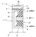
図1は、本発明に係るトルク変動吸収ダンパの好ましい実施の形態を、その軸心Oを通る平面で切断して示す断面図である。なお、以下の説明において、便宜上、図1における左側を正面側、右側を背面側と定義する。
【0010】
このトルク変動吸収ダンパにおいて、参照符号1は、内燃機関のクランクシャフトの軸端に取り付けられるハブであり、このハブ1は、金属材料で製作されたものであって、前記クランクシャフトの軸端に外挿固定されるボス部11と、その正面側の端部から外周側へ延びる円盤部12と、この円盤部12の外周端部から背面側へ延びボス部11と同心的に形成されたリム部13とからなる。
【0011】
ハブ1のリム部13の外周側には、プーリ2が配置されている。このプーリ2は、金属材料によって製作されたもので、外周面にポリV溝2aが形成されており、内周面における正面側寄りの部分と、ハブ1のリム部13の外周面との間には、ベアリング3が介在されている。ベアリング3は、PTFE等の耐摩耗性に優れた低摩擦係数の合成樹脂材料で環状に製作されたものであり、このベアリング3によって、プーリ2をハブ1に対して相対回転可能に同心支持している。
【0012】
ハブ1の円盤部12の背面側であって、ハブ1のボス部11とプーリ2との間には、慣性マス4が、同心的かつ円周方向相対変位可能に配置されている。慣性マス4は、鉄系材料など、比較的比重の大きい金属材料によって単純な円環状に製作されたものである。
【0013】
ハブ1のボス部11の外周面には、鋼材などの金属からなるインナースリーブ5が適当な締め代をもって圧入嵌着されており、このインナースリーブ5の外周面と、慣性マス4の内周面との間には、耐熱性、耐寒性及び機械的強度に優れたゴム状弾性材料からなる環状の内周弾性体6が加硫接着されている。
【0014】
一方、プーリ2の内周面における背面側寄りの部分には、鋼材などの金属からなるアウタースリーブ7が適当な締め代をもって圧入嵌着されており、このアウタースリーブ7の内周面と、慣性マス4の外周面との間には、耐熱性、耐寒性及び機械的強度に優れたゴム状弾性材料からなる環状の外周弾性体8が加硫接着されている。
【0015】
したがって、ハブ1とプーリ2は、インナースリーブ5、内周弾性体6、慣性マス4、外周弾性体8及びアウタースリーブ7を介して円周方向相対変位可能に連結されている。そして、内周弾性体6及び外周弾性体8は、ハブ1からプーリ2へクランクシャフトの駆動トルクを伝達するのに必要な強度を確保するために、所要の軸方向肉厚を有すると共に、捩り変形を受けた時の剪断応力が内周側と外周側とで均一になるように、それぞれ内周側で相対的に厚肉、外周側で相対的に薄肉となる断面形状に形成されている。
【0016】
慣性マス4、インナースリーブ5、内周弾性体6、アウタースリーブ7及び外周弾性体8は、互いに一体化された加硫成形体を構成している。そしてこの加硫成形体は、慣性マス4と、内径をハブ1のボス部11の外径よりも僅かに小径に形成したインナースリーブ5と、外径をプーリ2の内径よりも僅かに大径に形成したアウタースリーブ7を、予め表面に加硫接着剤を塗布したうえで、図示されていない金型のキャビティ内に互いに同心的にセットし、型締め後、慣性マス4とインナースリーブ5との間に画成された環状の賦形空間及び慣性マス4とアウタースリーブ7との間に画成された環状の賦形空間に、成形用未加硫ゴム材料を充填し、加熱・加圧することによって、内周弾性体6及び外周弾性体8を加硫成形と同時に、慣性マス4、インナースリーブ5及びアウタースリーブ7に加硫接着したものである。
【0017】
そして、慣性マス4、インナースリーブ5、内周弾性体6、アウタースリーブ7及び外周弾性体8からなる加硫成形体は、インナースリーブ5をハブ1の背面側からそのボス部11の外周面に圧入すると共に、アウタースリーブ7をプーリ2の内周面にその背面側から圧入することによって、図示のように組み込まれる。また、このとき、インナースリーブ5がボス部11への圧入過程で拡径変形を受けるので、内周弾性体6が径方向に予圧縮され、インナースリーブ5と慣性マス4の間で、内周弾性体6に加硫成形後の体積収縮によって生じた残留引張応力が解消される。同様に、アウタースリーブ7がプーリ2への圧入過程で縮径変形を受けるので、外周弾性体8が径方向に予圧縮され、アウタースリーブ7と慣性マス4の間で、外周弾性体8に加硫成形後の体積収縮によって生じた残留引張応力が解消される。
【0018】
内周弾性体6、慣性マス4、外周弾性体8及びプーリ2は、内周弾性体6及び外周弾性体8を慣性マス4に対するバネとする第一の副振動系D1と、プーリ2をマスとし、外周弾性体8をバネとする第二の副振動系D2を構成している。そして、慣性マス4に対して内周弾性体6と外周弾性体8は互いに並列の関係にあるため、内周弾性体6及び外周弾性体8によるバネ定数が高く、したがって第一の副振動系D1の捩り方向共振周波数が比較的高く設定されている。これに対し、プーリ2は慣性質量が大きく、このため第二の副振動系D2の捩り方向共振周波数は第一の副振動系D1よりも相対的に低いものとなっており、例えば内燃機関アイドリング等による捩り振動周波数域に設定されている。
【0019】
すなわち、このトルク変動吸収ダンパは、第一の副振動系D1と、第二の副振動系D2の、二つの副振動系が、慣性マス4、インナースリーブ5、内周弾性体6、アウタースリーブ7及び外周弾性体8からなる一つの加硫成形体の組み込みによって形成され、しかも、この加硫成形体が、ハブ1からプーリ2への駆動トルク伝達手段を兼ねるものである。このため、従来の技術のように、複数の加硫成形体を備える構造のトルク変動吸収ダンパに比較して、金型費用や成形工程が削減され、更にはプーリ2を第二の副振動系D2のマスとして利用しているので、二つの副振動系を有するにも拘らず、部品数が少なく、大型化を来すこともなく、安価に製造することができる。
【0020】
また、プーリ2及びその外周に巻き掛けられるVベルト(不図示)を介して接続される補機側のプーリを含む回転系をマスとし、内周弾性体6及び外周弾性体8をバネとする副振動系も存在するが、慣性質量が大きく、しかもこれに対して内周弾性体6及び外周弾性体8は直列の関係にあるため、バネ定数が低く、したがってその捩り方向共振周波数は、例えばアイドリングによる振動の周波数よりも十分に低いものとなっている。
【0021】
以上の構成を備える本形態のトルク変動吸収ダンパは、ハブ1のボス部11が内燃機関のクランクシャフトの軸端に装着されることによって、このクランクシャフトと共に回転される。クランクシャフトの駆動トルクは、ハブ1のボス部11から、インナースリーブ5、内周弾性体6、慣性マス4、外周弾性体8及びアウタースリーブ7を介してプーリ2へ伝達され、更にその外周のポリV溝2aに巻き掛けられるVベルトを介して、補器の回転系に伝達される。
【0022】
プーリ2には、Vベルトの張力によって軸心と垂直な方向の荷重が作用するが、プーリ2とハブ1のリム部13との間にはベアリング3が介在しているため、プーリ2の偏心が防止される。
【0023】
内燃機関の駆動は、吸気、圧縮、爆発(膨張)及び排気の各行程を繰り返しながら行われ、ピストンの往復運動をクランクシャフトの回転運動に変換しているため、クランクシャフトには、回転に伴って周期的なトルク変動を生じ、このトルク変動は、ハブ1に入力される。一方、回転中のプーリ2には回転方向の慣性が作用し、ひいては、ベルトを介して接続される補機側のプーリも含めた回転系の慣性が作用することによって、等速回転しようとするため、ハブ1とプーリ2との間で、内周弾性体6及び外周弾性体8が繰り返し捩り方向剪断変形を受けることによって、ハブ1からプーリ2への伝達トルクの変動を吸収し、補機への平滑な動力伝達を行うことができる。
【0024】
また、ハブ1に入力されるクランクシャフトの捩り振動が、内周弾性体6及び外周弾性体8と慣性マス4からなる第一の副振動系D1の共振周波数域、又は外周弾性体8及びプーリ2からなる第二の副振動系D2の共振周波数域にある場合は、この第一の副振動系D1又は第二の副振動系D2が捩り方向に共振する。そして、この共振は、入力振動と異なる位相角をもってなされるので、共振によるトルクは入力振動のトルクを相殺する方向へ生じ、このような動的吸振効果によって、クランクシャフトの捩り振動が有効に低減される。
【0025】
そして、第一の副振動系D1及び第二の副振動系D2には、互いに異なる共振周波数が設定されているため、上述の動的吸振効果が広い周波数域で発揮されることになり、優れた防振効果が得られる。
【0026】
【発明の効果】
以上の説明から明らかなように、請求項1の発明に係るトルク変動吸収ダンパによれば、慣性マス、内周弾性体及び外周弾性体からなる副振動系と、プーリ及び外周弾性体からなる副振動系によって、広い周波数域で動的吸振効果を得ることができる。また、複数の副振動系と、ハブからプーリへの駆動トルク伝達手段が、慣性マス、内周弾性体及び外周弾性体による一つの加硫成形体の組み込みによって構成され、プーリを一方の副振動系のマスとしているので、加硫成形工程が削減され、部品数も少なくなって、低コストで提供することができ、かつ大型化を防止することができる。
【図面の簡単な説明】
【図1】本発明に係るトルク変動吸収ダンパの好ましい実施の形態を、その軸心Oを通る平面で切断して示す半断面図である。
【符号の説明】
1 ハブ
11 ボス部
12 円盤部
13 リム部
2 プーリ
2a ポリV溝
3 ベアリング
4 慣性マス
5 インナースリーブ
6 内周弾性体
7 アウタースリーブ
8 外周弾性体
D1 第一の副振動系
D2 第二の副振動系[0001]
TECHNICAL FIELD OF THE INVENTION
The present invention relates to a torque fluctuation absorbing damper that transmits a driving torque from a driving shaft in an internal combustion engine or the like to another rotating device and absorbs a fluctuation in the torque.
[0002]
[Prior art]
A part of the driving force from the internal combustion engine of the vehicle is provided to auxiliary devices and the like via an endless belt from a pulley provided at the tip of the crankshaft, but the crankshaft is accompanied by torque fluctuation due to each stroke of the internal combustion engine. Since the pulley is rotated, a torque fluctuation absorbing damper for absorbing torque fluctuation and smoothing the transmission torque is used for the pulley.
[0003]
As a typical conventional technique of this type of torque fluctuation absorbing damper, a decoupled damper pulley described in Patent Document 1 is known. That is, the decoupled damper pulley is connected to the outer periphery of a hub member that is attached to the shaft end of the crankshaft and rotates integrally with the pulley member via the first rubber-like elastic member. It has a structure in which inertial masses are connected via a second rubber-like elastic member. The secondary vibration system composed of the second rubber-like elastic member and the inertial mass reduces the torsional vibration of the crankshaft by the dynamic vibration absorption effect caused by resonating in the torsional direction in a predetermined frequency range. The drive torque input to the hub member is transmitted to the pulley member while absorbing the torque fluctuation by the torsional shearing action of the first rubber-like elastic member.
[0004]
[Patent Document 1]
Utility Model Registration No. 2605662 (FIG. 1, 0006 to 0009)
[0005]
[Problems to be solved by the invention]
However, according to the prior art, a molded body in which a first rubber-like elastic member is vulcanized and bonded between a hub member and a pulley member, and a second rubber-like elastic member is added between a hub member and an inertial mass. Two vulcanized molded articles of the sulfur-adhered molded article were required, so that the production cost was high.
[0006]
Further, in this type of torque fluctuation absorbing damper, dynamic vibration absorption is performed only by a single sub-vibration system including the second rubber-like elastic member and the inertial mass. Was narrow. In order to expand the frequency range in which the dynamic vibration absorbing function can be achieved, it is conceivable to add a sub-vibration system including an inertial mass and a rubber-like elastic member, but in this case, it is necessary to further increase the number of parts. There is a problem that the manufacturing cost is increased and the size is increased.
[0007]
The present invention has been made in view of the above-described problems, and a technical problem of the present invention is to provide a torque fluctuation absorbing damper that can be manufactured at a low cost and has an expanded vibration damping region by a dynamic vibration absorbing function. It is in.
[0008]
[Means for Solving the Problems]
As a means for effectively solving the above-mentioned technical problem, a torque fluctuation absorbing damper according to the invention of claim 1 includes a hub attached to a rotating shaft, and a hub concentric with the hub and capable of relative displacement in a circumferential direction. The arranged pulley is constituted by an inertial mass arranged so as to be relatively displaceable in the circumferential direction between the hub and the pulley, and an inner periphery made of a rubber-like elastic material interposed between the hub and the inertial mass. An elastic body and an outer peripheral elastic body made of a rubber-like elastic material interposed between the pulley and the inertial mass are connected to each other.
[0009]
BEST MODE FOR CARRYING OUT THE INVENTION
FIG. 1 is a sectional view showing a preferred embodiment of a torque fluctuation absorbing damper according to the present invention by cutting along a plane passing through an axis O thereof. In the following description, the left side in FIG. 1 is defined as a front side and the right side is defined as a back side for convenience.
[0010]
In this torque fluctuation absorbing damper, reference numeral 1 denotes a hub attached to a shaft end of a crankshaft of an internal combustion engine, and the hub 1 is made of a metal material. A
[0011]
The pulley 2 is arranged on the outer peripheral side of the
[0012]
On the back side of the
[0013]
An
[0014]
On the other hand, an
[0015]
Therefore, the hub 1 and the pulley 2 are connected via the
[0016]
The inertial mass 4,
[0017]
The vulcanized molded body including the inertial mass 4, the
[0018]
The inner peripheral elastic body 6, the inertial mass 4, the outer peripheral elastic body 8, and the pulley 2 are composed of a first auxiliary vibration system D1 in which the inner peripheral elastic body 6 and the outer peripheral elastic body 8 are springs for the inertial mass 4, and the pulley 2 And a second auxiliary vibration system D2 having the outer peripheral elastic body 8 as a spring. Since the inner peripheral elastic body 6 and the outer peripheral elastic body 8 are in parallel with each other with respect to the inertial mass 4, the spring constant of the inner peripheral elastic body 6 and the outer peripheral elastic body 8 is high, and therefore, the first auxiliary vibration system The torsional resonance frequency of D1 is set relatively high. On the other hand, the pulley 2 has a large inertial mass, so that the resonance frequency in the torsional direction of the second sub-vibration system D2 is relatively lower than that of the first sub-vibration system D1. And so on.
[0019]
That is, in the torque fluctuation absorbing damper, the two sub-vibration systems of the first sub-vibration system D1 and the second sub-vibration system D2 are composed of an inertia mass 4, an
[0020]
In addition, a rotating system including a pulley on the auxiliary machine side connected via a pulley 2 and a V belt (not shown) wound around the outer periphery thereof is used as a mass, and the inner peripheral elastic body 6 and the outer peripheral elastic body 8 are used as springs. Although there is a sub-vibration system, since the inertial mass is large, and the inner elastic body 6 and the outer elastic body 8 are in series with each other, the spring constant is low, and the resonance frequency in the torsional direction is, for example, The frequency is sufficiently lower than the frequency of vibration due to idling.
[0021]
The torque fluctuation absorbing damper according to the present embodiment having the above-described configuration is rotated together with the crankshaft of the internal combustion engine by mounting the
[0022]
A load in a direction perpendicular to the axis acts on the pulley 2 due to the tension of the V-belt. However, since the
[0023]
The internal combustion engine is driven while repeating the steps of intake, compression, explosion (expansion), and exhaust, and converts the reciprocating motion of the piston into the rotational motion of the crankshaft. The torque fluctuation is input to the hub 1. On the other hand, the inertia of the rotating pulley 2 acts on the rotating pulley 2 and, by extension, the inertia of the rotating system including the auxiliary pulley connected via a belt acts on the pulley 2 to rotate at a constant speed. Therefore, the inner elastic body 6 and the outer elastic body 8 are repeatedly subjected to the shearing deformation in the torsional direction between the hub 1 and the pulley 2, thereby absorbing the fluctuation of the transmission torque from the hub 1 to the pulley 2, and Power can be smoothly transmitted to the motor.
[0024]
The torsional vibration of the crankshaft input to the hub 1 is caused by the resonance frequency range of the first sub-vibration system D1 including the inner peripheral elastic body 6 and the outer peripheral elastic body 8 and the inertial mass 4, or the outer peripheral elastic body 8 and the pulley. 2, the first sub-vibration system D1 or the second sub-vibration system D2 resonates in the torsional direction. Since this resonance occurs at a phase angle different from that of the input vibration, the torque due to the resonance is generated in a direction to cancel the torque of the input vibration, and the torsional vibration of the crankshaft is effectively reduced by such a dynamic vibration absorbing effect. Is done.
[0025]
Since different resonance frequencies are set for the first sub-vibration system D1 and the second sub-vibration system D2, the above-described dynamic vibration absorbing effect is exerted in a wide frequency range. The anti-vibration effect is obtained.
[0026]
【The invention's effect】
As apparent from the above description, according to the torque fluctuation absorbing damper according to the first aspect of the present invention, the auxiliary vibration system including the inertial mass, the inner peripheral elastic body and the outer peripheral elastic body, and the auxiliary vibration system including the pulley and the outer peripheral elastic body. The vibration system can provide a dynamic vibration absorbing effect in a wide frequency range. Also, the plurality of sub-vibration systems and the drive torque transmitting means from the hub to the pulley are configured by incorporating one vulcanized molded body by the inertial mass, the inner peripheral elastic body and the outer peripheral elastic body, and Since the system mass is used, the vulcanization molding process is reduced, the number of parts is reduced, the product can be provided at low cost, and an increase in size can be prevented.
[Brief description of the drawings]
FIG. 1 is a half sectional view showing a preferred embodiment of a torque fluctuation absorbing damper according to the present invention by cutting along a plane passing through an axis O thereof.
[Explanation of symbols]
DESCRIPTION OF SYMBOLS 1
Claims (1)
Priority Applications (1)
| Application Number | Priority Date | Filing Date | Title |
|---|---|---|---|
| JP2002361705A JP2004190818A (en) | 2002-12-13 | 2002-12-13 | Torque fluctuation absorbing damper |
Applications Claiming Priority (1)
| Application Number | Priority Date | Filing Date | Title |
|---|---|---|---|
| JP2002361705A JP2004190818A (en) | 2002-12-13 | 2002-12-13 | Torque fluctuation absorbing damper |
Publications (1)
| Publication Number | Publication Date |
|---|---|
| JP2004190818A true JP2004190818A (en) | 2004-07-08 |
Family
ID=32760340
Family Applications (1)
| Application Number | Title | Priority Date | Filing Date |
|---|---|---|---|
| JP2002361705A Pending JP2004190818A (en) | 2002-12-13 | 2002-12-13 | Torque fluctuation absorbing damper |
Country Status (1)
| Country | Link |
|---|---|
| JP (1) | JP2004190818A (en) |
Cited By (3)
| Publication number | Priority date | Publication date | Assignee | Title |
|---|---|---|---|---|
| CN104896007A (en) * | 2015-04-02 | 2015-09-09 | 国电联合动力技术有限公司 | A transmission system torsional vibration reducing method and application thereof |
| EP3189246A4 (en) * | 2014-09-02 | 2018-04-18 | Dayco IP Holdings, LLC | Torsional vibration dampers having dual elastomeric members |
| CN109185379A (en) * | 2018-10-30 | 2019-01-11 | 株洲时代新材料科技股份有限公司 | Tunable multilayer dampened power bump leveller and its fabrication and installation method, oscillation damping method |
-
2002
- 2002-12-13 JP JP2002361705A patent/JP2004190818A/en active Pending
Cited By (3)
| Publication number | Priority date | Publication date | Assignee | Title |
|---|---|---|---|---|
| EP3189246A4 (en) * | 2014-09-02 | 2018-04-18 | Dayco IP Holdings, LLC | Torsional vibration dampers having dual elastomeric members |
| CN104896007A (en) * | 2015-04-02 | 2015-09-09 | 国电联合动力技术有限公司 | A transmission system torsional vibration reducing method and application thereof |
| CN109185379A (en) * | 2018-10-30 | 2019-01-11 | 株洲时代新材料科技股份有限公司 | Tunable multilayer dampened power bump leveller and its fabrication and installation method, oscillation damping method |
Similar Documents
| Publication | Publication Date | Title |
|---|---|---|
| JP4716012B2 (en) | Torque fluctuation absorbing damper | |
| JP2004278726A (en) | Torque fluctuation absorbing damper | |
| JP6682261B2 (en) | Crank pulley | |
| JP2004340169A (en) | Torque fluctuation absorbing damper | |
| JP2004286077A (en) | Torque fluctuation absorbing damper | |
| JP2004190818A (en) | Torque fluctuation absorbing damper | |
| JP6100070B2 (en) | Torque fluctuation absorbing damper | |
| JP2004340170A (en) | Damper | |
| JP2000320613A (en) | Torque fluctuation absorbing damper | |
| JP2004108528A (en) | Torque fluctuation absorption damper | |
| JP2004176880A (en) | Torque fluctuation absorbing damper and its manufacturing method | |
| JP4662044B2 (en) | Torque fluctuation absorbing damper | |
| JP2001248689A (en) | Torque fluctuation absorbing damper | |
| JP2004028177A (en) | Torque fluctuation absorbing damper | |
| JP3994278B2 (en) | Torque fluctuation absorbing damper | |
| JP4006582B2 (en) | Torque fluctuation absorbing damper | |
| JP4743391B2 (en) | Torque fluctuation absorbing damper | |
| JP2004278618A (en) | Torque fluctuation absorbing damper | |
| JP2000346136A (en) | Pulley coupling | |
| JP2003343652A (en) | Torque variation absorbing damper | |
| JP2004162768A (en) | Torque fluctuation absorbing damper | |
| JP2001208134A (en) | Torque fluctuation absorbing damper | |
| JP4798364B2 (en) | Torque fluctuation absorbing damper | |
| JP4022741B2 (en) | Damper pulley | |
| JP2004144253A (en) | Torque fluctuation absorbing damper |
Legal Events
| Date | Code | Title | Description |
|---|---|---|---|
| A621 | Written request for application examination |
Free format text: JAPANESE INTERMEDIATE CODE: A621 Effective date: 20051025 |
|
| A977 | Report on retrieval |
Free format text: JAPANESE INTERMEDIATE CODE: A971007 Effective date: 20080307 |
|
| A131 | Notification of reasons for refusal |
Free format text: JAPANESE INTERMEDIATE CODE: A131 Effective date: 20080416 |
|
| A02 | Decision of refusal |
Effective date: 20080812 Free format text: JAPANESE INTERMEDIATE CODE: A02 |