JP2004190825A - Orifice type steam trap - Google Patents
Orifice type steam trap Download PDFInfo
- Publication number
- JP2004190825A JP2004190825A JP2002362026A JP2002362026A JP2004190825A JP 2004190825 A JP2004190825 A JP 2004190825A JP 2002362026 A JP2002362026 A JP 2002362026A JP 2002362026 A JP2002362026 A JP 2002362026A JP 2004190825 A JP2004190825 A JP 2004190825A
- Authority
- JP
- Japan
- Prior art keywords
- screen
- outlet
- orifice
- inlet
- trap
- Prior art date
- Legal status (The legal status is an assumption and is not a legal conclusion. Google has not performed a legal analysis and makes no representation as to the accuracy of the status listed.)
- Granted
Links
- 238000005192 partition Methods 0.000 claims abstract description 6
- 239000000428 dust Substances 0.000 description 2
- 230000000694 effects Effects 0.000 description 2
- 230000000149 penetrating effect Effects 0.000 description 1
- 239000000126 substance Substances 0.000 description 1
- XLYOFNOQVPJJNP-UHFFFAOYSA-N water Substances O XLYOFNOQVPJJNP-UHFFFAOYSA-N 0.000 description 1
Images
Landscapes
- Filtration Of Liquid (AREA)
- Details Of Valves (AREA)
Abstract
Description
【0001】
【発明の属する技術分野】
本発明は、蒸気輸送管や蒸気使用機器等の蒸気配管系に発生する蒸気が凝縮した復水を常時開孔している小径のオリフィスから自動的に系外に排出するオリフィス式スチームトラップに関し、特に、オリフィスの入口側にスクリーンを設けたものに関する。
【0002】
【従来の技術】
【特許文献1】
特開2001−27389
従来のスクリーンを備えたオリフィス式スチームトラップは、例えば、特開2001−27389に示されている。ここに開示されたものは、トラップケーシングに形成した入口と出口の間にオリフィスを有する隔壁部材を設け、オリフィスの入口側にスクリーンを設け、入口側の異物をスクリーンで捕捉して復水をオリフィスから出口側に排出するものである。
【0003】
【発明が解決しようとする課題】
上記従来のオリフィス式スチームトラップでは、スクリーンで捕捉した異物を取り除くために、定期的に蒸気配管系からトラップを取外してスクリーンを洗浄しなければならない問題点があった。本発明は、従来技術の上記した問題点に注目し、蒸気配管系からトラップを取外さずにスクリーンを洗浄できるオリフィス式スチームトラップを提供することを技術的課題とする。
【0004】
【課題を解決するための手段】
上記の技術的課題を解決するために講じた本発明の技術的手段は、トラップケーシングに形成した入口と出口の間に流通孔を有する弁ボールを回転可能に配置し、弁ボールの流通孔内にオリフィスを有する隔壁部材を設け、オリフィスの一方の開口端側の流通孔内に第1スクリーンを他方の開口端側の流通孔内に第2スクリーンを設けたことを特徴とするオリフィス式スチームトラップにある。
【0005】
【発明の実施の形態】
本発明のオリフィス式スチームトラップは、弁ボールを回転操作して、第1スクリーンを入口側に第2スクリーンを出口側に対向させた第1状態と、第2スクリーンを入口側に第1スクリーンを出口側に対向させた第2状態に切り替えて使用する。第1状態においては、入口側の異物を第1スクリーンで捕捉して復水をオリフィスから第2スクリーンを通して出口側に排出すると共に第2スクリーンで捕捉していた異物を出口側に排除する。第2状態においては、入口側の異物を第2スクリーンで捕捉して復水をオリフィスから第1スクリーンを通して出口側に排出すると共に第1スクリーンで捕捉していた異物を出口側に排除する。このように、弁ボールを回転操作することにより、蒸気配管系からトラップを取外さずにスクリーンを洗浄することができる。
【0006】
【実施例】
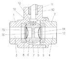
上記の技術的手段の具体例を示す実施例を説明する(図1参照)。入口側部材1に出口側部材2をねじ結合してトラップケーシングを形成する。入口側部材1に入口3を形成し、出口側部材2に入口3と同軸上の出口4を形成し、トラップケーシング内に入口3と出口4の連通する弁室5を形成する。
【0007】
弁室5内に流通孔6を有する弁ボール7を配置する。流通孔6は入口3と出口4と同軸上に形成する。弁ボール7の入口3側に環状弁座8を出口4側に環状弁座9を配置する。弁ボール7にキー溝10を設けて、本体1を貫通する弁軸11の下端のキー部12を係合させる。弁軸11にはハンドル(図示せず)を取り付けて、弁ボール7を回転可能にする。本体1と弁軸11の間に気密保持用のガスケット13を介在させる。
【0008】
流通孔6内にオリフィス14を有する隔壁部材15を弁ボール7に一体に設ける。オリフィス14の一方の開口端側の流通孔6内にゴミ等の異物を捕捉する第1スクリーン16を止め輪で取り付け、他方の開口端側の流通孔6内にゴミ等の異物を捕捉する第2スクリーン17を止め輪で取り付ける。
【0009】
図示の状態は、第1スクリーン16を入口3側に第2スクリーン17を出口4側に対向させた第1状態である。入口3側から流れてくる異物は第1スクリーン16で捕捉され復水はオリフィス14から第2スクリーン17を通して出口4側に排出される。第1スクリーン16で捕捉した異物を排除する場合は、図示の状態から弁ボール7を180度回転操作して、第2スクリーン17を入口3側に第1スクリーン16を出口4側に対向させた第2状態に切り替える。入口3側から流れてくる異物は第2スクリーン17で捕捉され復水はオリフィス14から第1スクリーン16を通して出口4側に排出されると共に第1スクリーン16で捕捉されていた異物は出口3側に排除される。第2スクリーン17で捕捉した異物を排除する場合は、弁ボール7を180度回転操作して、第1スクリーン16を入口3側に第2スクリーン17を出口4側に対向させた図示の第1状態に切り替える。入口3側から流れてくる異物は第1スクリーン16で捕捉され復水はオリフィス14から第2スクリーン17を通して出口4側に排出されると共に第2スクリーン17で捕捉されていた異物は出口3側に排除される。
【0010】
【発明の効果】
上記のように本発明によるオリフィス式スチームトラップは、弁ボールを回転操作して、第1スクリーンを入口側に第2スクリーンを出口側に対向させた第1状態と、第2スクリーンを入口側に第1スクリーンを出口側に対向させた第2状態に切り替えることにより、第1スクリーンあるいは第2スクリーンで捕捉していた異物を出口側に排除することができるので、蒸気配管系からトラップを取外さずにスクリーンを洗浄することができるという優れた効果がある。
【図面の簡単な説明】
【図1】本発明のオリフィス式スチームトラップの実施例の断面図である。
【符号の説明】
1 入口側部材
2 出口側部材
3 入口
4 出口
5 弁室
6 流通孔
7 弁ボール
11 弁軸
14 オリフィス
15 隔壁部材
16 第1スクリーン
17 第2スクリーン[0001]
TECHNICAL FIELD OF THE INVENTION
The present invention relates to an orifice type steam trap that automatically discharges condensed water generated in a steam piping system such as a steam transport pipe or a steam-using device from a small-diameter orifice that is always open to the outside of the system. In particular, the present invention relates to a screen provided with a screen on the inlet side of the orifice.
[0002]
[Prior art]
[Patent Document 1]
JP-A-2001-27389
A conventional orifice type steam trap having a screen is disclosed in, for example, JP-A-2001-27389. What is disclosed herein is that a partition member having an orifice is provided between an inlet and an outlet formed in a trap casing, a screen is provided on the inlet side of the orifice, foreign matter on the inlet side is captured by the screen, and condensate is condensed in the orifice. From the outlet to the exit side.
[0003]
[Problems to be solved by the invention]
In the above-mentioned conventional orifice type steam trap, there was a problem that the trap had to be periodically removed from the steam piping system to clean the screen in order to remove foreign matters caught by the screen. An object of the present invention is to provide an orifice type steam trap which can wash a screen without removing the trap from a steam piping system, focusing on the above-mentioned problems of the prior art.
[0004]
[Means for Solving the Problems]
The technical means of the present invention taken to solve the above technical problem is to dispose a valve ball having a flow hole between an inlet and an outlet formed in a trap casing so as to be rotatable, An orifice-type steam trap, wherein a partition wall member having an orifice is provided on the first orifice, and a first screen is provided in a communication hole on one opening end side of the orifice and a second screen is provided in a communication hole on the other opening end side. It is in.
[0005]
BEST MODE FOR CARRYING OUT THE INVENTION
The orifice type steam trap of the present invention rotates the valve ball to set the first screen to the inlet side and the second screen to the outlet side, and the second screen to the first screen on the inlet side. It is used by switching to the second state facing the outlet side. In the first state, foreign matter on the inlet side is captured by the first screen, condensate is discharged from the orifice through the second screen to the outlet side, and foreign matter captured by the second screen is removed to the outlet side. In the second state, the foreign matter on the inlet side is captured by the second screen, the condensate is discharged from the orifice through the first screen to the outlet side, and the foreign matter captured by the first screen is removed to the outlet side. In this way, by rotating the valve ball, the screen can be washed without removing the trap from the steam piping system.
[0006]
【Example】
An embodiment showing a specific example of the above technical means will be described (see FIG. 1). The
[0007]
A
[0008]
A
[0009]
The illustrated state is a first state in which the
[0010]
【The invention's effect】
As described above, the orifice type steam trap according to the present invention rotates the valve ball so that the first screen faces the inlet side and the second screen faces the outlet side, and the second screen faces the inlet side. By switching the first screen to the second state in which the first screen is opposed to the outlet side, foreign substances trapped by the first screen or the second screen can be removed to the outlet side, so that the trap is removed from the steam piping system. There is an excellent effect that the screen can be washed without using.
[Brief description of the drawings]
FIG. 1 is a sectional view of an embodiment of an orifice type steam trap according to the present invention.
[Explanation of symbols]
DESCRIPTION OF SYMBOLS 1
Claims (1)
Priority Applications (1)
| Application Number | Priority Date | Filing Date | Title |
|---|---|---|---|
| JP2002362026A JP4115822B2 (en) | 2002-12-13 | 2002-12-13 | Orifice type steam trap |
Applications Claiming Priority (1)
| Application Number | Priority Date | Filing Date | Title |
|---|---|---|---|
| JP2002362026A JP4115822B2 (en) | 2002-12-13 | 2002-12-13 | Orifice type steam trap |
Publications (2)
| Publication Number | Publication Date |
|---|---|
| JP2004190825A true JP2004190825A (en) | 2004-07-08 |
| JP4115822B2 JP4115822B2 (en) | 2008-07-09 |
Family
ID=32760594
Family Applications (1)
| Application Number | Title | Priority Date | Filing Date |
|---|---|---|---|
| JP2002362026A Expired - Fee Related JP4115822B2 (en) | 2002-12-13 | 2002-12-13 | Orifice type steam trap |
Country Status (1)
| Country | Link |
|---|---|
| JP (1) | JP4115822B2 (en) |
Cited By (1)
| Publication number | Priority date | Publication date | Assignee | Title |
|---|---|---|---|---|
| JP2016001021A (en) * | 2014-06-11 | 2016-01-07 | 中国電力株式会社 | Flow regulator with rotating backwash function |
-
2002
- 2002-12-13 JP JP2002362026A patent/JP4115822B2/en not_active Expired - Fee Related
Cited By (1)
| Publication number | Priority date | Publication date | Assignee | Title |
|---|---|---|---|---|
| JP2016001021A (en) * | 2014-06-11 | 2016-01-07 | 中国電力株式会社 | Flow regulator with rotating backwash function |
Also Published As
| Publication number | Publication date |
|---|---|
| JP4115822B2 (en) | 2008-07-09 |
Similar Documents
| Publication | Publication Date | Title |
|---|---|---|
| CN113330169A (en) | Drain connector system | |
| JP4115822B2 (en) | Orifice type steam trap | |
| KR100310434B1 (en) | An apparatus for filtering gas | |
| JP2004190827A (en) | Orifice type steam trap | |
| JP2004190826A (en) | Orifice type steam trap | |
| JPS6037515Y2 (en) | Ball valve type orifice type steam trap | |
| CN106870757A (en) | A kind of Filtering ball valve | |
| CN206845962U (en) | A kind of Filtering ball valve | |
| KR200321139Y1 (en) | Drain filter | |
| JPS5880493A (en) | Strainer | |
| RU2233201C1 (en) | Duct extractor with valve hydroseal | |
| JP3854806B2 (en) | Strainer with blow function | |
| KR200389968Y1 (en) | Strainer establishment structure for waterworks piping | |
| CN218653347U (en) | Filter device of one-way water flow channel | |
| KR200193019Y1 (en) | An apparatus for filtering gas | |
| KR200444764Y1 (en) | Sedimentation filter | |
| JP4847135B2 (en) | Drain trap | |
| JP2008121871A (en) | Drain trap | |
| JP6138646B2 (en) | Drainage device connection structure | |
| FI92743C (en) | Odor trap and drain flushing device | |
| JP2005230768A (en) | Strainer apparatus | |
| JP4865409B2 (en) | Drain trap | |
| JP4865410B2 (en) | Drain trap | |
| JP7337346B2 (en) | Joint member | |
| JP2004218724A (en) | Orifice type steam trap |
Legal Events
| Date | Code | Title | Description |
|---|---|---|---|
| A621 | Written request for application examination |
Free format text: JAPANESE INTERMEDIATE CODE: A621 Effective date: 20050823 |
|
| A977 | Report on retrieval |
Free format text: JAPANESE INTERMEDIATE CODE: A971007 Effective date: 20080326 |
|
| TRDD | Decision of grant or rejection written | ||
| A01 | Written decision to grant a patent or to grant a registration (utility model) |
Free format text: JAPANESE INTERMEDIATE CODE: A01 Effective date: 20080415 |
|
| A61 | First payment of annual fees (during grant procedure) |
Free format text: JAPANESE INTERMEDIATE CODE: A61 Effective date: 20080416 |
|
| FPAY | Renewal fee payment (event date is renewal date of database) |
Free format text: PAYMENT UNTIL: 20110425 Year of fee payment: 3 |
|
| R150 | Certificate of patent or registration of utility model |
Free format text: JAPANESE INTERMEDIATE CODE: R150 |
|
| FPAY | Renewal fee payment (event date is renewal date of database) |
Free format text: PAYMENT UNTIL: 20110425 Year of fee payment: 3 |
|
| FPAY | Renewal fee payment (event date is renewal date of database) |
Free format text: PAYMENT UNTIL: 20110425 Year of fee payment: 3 |
|
| FPAY | Renewal fee payment (event date is renewal date of database) |
Free format text: PAYMENT UNTIL: 20120425 Year of fee payment: 4 |
|
| FPAY | Renewal fee payment (event date is renewal date of database) |
Free format text: PAYMENT UNTIL: 20130425 Year of fee payment: 5 |
|
| FPAY | Renewal fee payment (event date is renewal date of database) |
Free format text: PAYMENT UNTIL: 20130425 Year of fee payment: 5 |
|
| FPAY | Renewal fee payment (event date is renewal date of database) |
Free format text: PAYMENT UNTIL: 20140425 Year of fee payment: 6 |
|
| R250 | Receipt of annual fees |
Free format text: JAPANESE INTERMEDIATE CODE: R250 |
|
| R250 | Receipt of annual fees |
Free format text: JAPANESE INTERMEDIATE CODE: R250 |
|
| LAPS | Cancellation because of no payment of annual fees |