JP2004190852A - Fluid controller - Google Patents
Fluid controller Download PDFInfo
- Publication number
- JP2004190852A JP2004190852A JP2003271267A JP2003271267A JP2004190852A JP 2004190852 A JP2004190852 A JP 2004190852A JP 2003271267 A JP2003271267 A JP 2003271267A JP 2003271267 A JP2003271267 A JP 2003271267A JP 2004190852 A JP2004190852 A JP 2004190852A
- Authority
- JP
- Japan
- Prior art keywords
- handle
- open
- cover
- fluid
- fluid passage
- Prior art date
- Legal status (The legal status is an assumption and is not a legal conclusion. Google has not performed a legal analysis and makes no representation as to the accuracy of the status listed.)
- Granted
Links
- 239000012530 fluid Substances 0.000 title claims abstract description 114
- 230000002093 peripheral effect Effects 0.000 claims description 13
- 230000006835 compression Effects 0.000 description 4
- 238000007906 compression Methods 0.000 description 4
- 230000000903 blocking effect Effects 0.000 description 2
- 230000007246 mechanism Effects 0.000 description 2
- QNRATNLHPGXHMA-XZHTYLCXSA-N (r)-(6-ethoxyquinolin-4-yl)-[(2s,4s,5r)-5-ethyl-1-azabicyclo[2.2.2]octan-2-yl]methanol;hydrochloride Chemical compound Cl.C([C@H]([C@H](C1)CC)C2)CN1[C@@H]2[C@H](O)C1=CC=NC2=CC=C(OCC)C=C21 QNRATNLHPGXHMA-XZHTYLCXSA-N 0.000 description 1
- 230000007423 decrease Effects 0.000 description 1
- 238000009434 installation Methods 0.000 description 1
- 230000007257 malfunction Effects 0.000 description 1
- 238000004519 manufacturing process Methods 0.000 description 1
- 230000000149 penetrating effect Effects 0.000 description 1
Images

Landscapes
- Indication Of The Valve Opening Or Closing Status (AREA)
Abstract
Description
この発明は、流体制御器に関し、特に、流体通路の遮断または開放を外から認知できる開閉状態機能付きの流体制御器に関する。 The present invention relates to a fluid controller, and more particularly, to a fluid controller having an open / close state function that can externally recognize whether a fluid passage is blocked or opened.
ハンドルを回転させることにより流体通路が開閉される制御器は、よく知られているが、この種の流体制御器では、流体が有害ガスなどである場合には、誤作動をなくすために流体通路の遮断または開放を外から認知できる開閉表示機能付きとすることが要望されている。開閉表示機能付きの制御器については、各種の提案がなされている(例えば、特許文献1参照)。
特許文献1に記載の制御器では、開閉表示機能の付加が部品数の増加および構成の複雑化につながり、製造コストが高くつくという問題があった。
In the controller described in
この発明の目的は、開閉表示機能を有しかつ構成が簡単な流体制御器を提供することにある。 An object of the present invention is to provide a fluid controller having an open / close display function and a simple configuration.
この発明による制御器は、流体通路が設けられている本体と、上下移動させられることにより本体の通路を開閉する弁棒と、本体に固定されて弁棒を案内する円筒状ボンネットと、ボンネットの頂部に固定されたカバーと、カバーよりも上方に突出させられた弁棒上端部に固定され回転させられることにより弁棒を上下移動させるハンドルとを備えている制御器において、ハンドルが90°回転させられることにより通路の遮断開放状態が切り替わるようになされるとともに、ハンドルが平面より見てその中央部にくびれ部を有する形状とされ、カバー上面に記載された開閉表示文字がハンドルのくびれ部から視認可能とされていることを特徴とするものである。 A controller according to the present invention includes a main body provided with a fluid passage, a valve stem for opening and closing the passage of the main body by being moved up and down, a cylindrical bonnet fixed to the main body and guiding the valve stem, and a bonnet. A controller having a cover fixed to a top portion and a handle fixed to an upper end portion of a valve stem protruding above the cover and rotated to move the valve stem up and down by rotating the handle by 90 ° As a result, the open / closed state of the passage is switched, and the handle has a shape having a constricted portion at the center thereof when viewed from a plane, and the opening / closing display character written on the upper surface of the cover is from the constricted portion of the handle. It is characterized by being visible.
ハンドル形状は、平面より見て略長円形、略長方形、略菱形などとなされ、その長手方向の中央部にくびれ部が設けられる。この場合に、ハンドルの長手方向と流体通路の方向が一致したときに開、ハンドルの長手方向と流体通路の方向が直交したときに閉とすることが好ましい。ハンドルを90°回転させた際に通路を遮断開放状態するための構成は、限定されるものでなく、カム手段、ねじ手段、ばね手段などが単独または組み合わされて構成される。 The handle shape is substantially oval, substantially rectangular, substantially rhombic when viewed from a plane, and a constricted portion is provided at the center in the longitudinal direction. In this case, it is preferable to open when the longitudinal direction of the handle and the direction of the fluid passage coincide, and to close when the longitudinal direction of the handle and the direction of the fluid passage are orthogonal. The configuration for blocking and opening the passage when the handle is rotated by 90 ° is not limited, and is constituted by a cam means, a screw means, a spring means or the like alone or in combination.
この発明の流体制御器によると、ハンドルの中央部にくびれ部を設けることにより、ハンドルの上から見た場合にこのくびれ部を通してカバー上面が視認可能となる。したがって、カバー上面に開または閉の文字などを記載しておくことにより、流体制御器が従来有していた機能を阻害することなくかつ部品数を増加させずに開閉表示を行うことができる。 According to the fluid controller of the present invention, by providing the constricted portion at the center of the handle, the upper surface of the cover can be visually recognized through the constricted portion when viewed from above the handle. Therefore, by writing characters such as open or closed on the upper surface of the cover, the open / close display can be performed without obstructing the function of the fluid controller conventionally and without increasing the number of parts.
ハンドルは、カバーに嵌め合わせられる嵌め合わせ部と、嵌め合わせ部の上端に一体に設けられかつ平面から見て中央部がくびれた把手部とからなることがある。このようにすると、ハンドルの制御器本体への取付けが容易となり、かつハンドル操作もしやすくなる。 The handle may include a fitting portion fitted to the cover, and a handle portion provided integrally with the upper end of the fitting portion and having a central portion narrowed when viewed from a plane. In this case, the handle can be easily attached to the controller body, and the handle can be easily operated.
ハンドルの嵌め合わせ部の周壁に、のぞき窓が設けられるとともに、カバー部の周面に、のぞき窓から視認可能な開閉表示文字が記載されていることがある。このようにすると、制御器の上方からだけでなく、側面からも開閉状態を確認することができ、誤操作の危険性をより少なくすることができる。 In some cases, a viewing window is provided on the peripheral wall of the fitting portion of the handle, and on the peripheral surface of the cover portion, opening / closing display characters that are visible from the viewing window are described. In this way, the open / closed state can be checked not only from above the controller but also from the side, and the risk of erroneous operation can be further reduced.
本体は、互いに180°離れた位置に設けられた2つの流体通路開口および各開口に配管を接続するための継手部を有していることがあり、また、本体は、互いに90°離れた位置に設けられた2つの流体通路開口および各開口に配管を接続するための継手部を有していることがあり、さらにまた、3つの流体通路開口および各開口に配管を接続するための継手部を有していることがあり、また、本体は、互いに90°離れた位置に設けられた4つの流体通路開口および各開口に配管を接続するための継手部を有していることがある。こうして、ハンドルとしては同じものを使用して、本体を変更することにより、2方弁、3方弁および4方弁のいずれにも対応することができる。この場合に、カバーの上面に90°おきに、開表示および閉表示のいずれか一方が施されていることが好ましい。 The body may have two fluid passage openings located 180 ° apart from each other and a joint for connecting tubing to each opening, and the body may be located 90 ° apart from each other. May be provided with two fluid passage openings and a joint for connecting a pipe to each of the openings, and further, a joint for connecting a pipe to the three fluid passage openings and each of the openings. In addition, the main body may have four fluid passage openings provided at positions separated from each other by 90 ° and joints for connecting pipes to the respective openings. Thus, by using the same handle and changing the main body, it is possible to deal with any of the two-way valve, the three-way valve and the four-way valve. In this case, it is preferable that one of the open display and the closed display is given on the upper surface of the cover at intervals of 90 °.
開口が2つの場合、カバーには、90°置きに「OPEN」および「CLOSE」が順に記載されるが、開口が3つ以上設けられる場合には、通常は、90°置きに「OPEN」および「CLOSE」が順に記載され、必要に応じ、すなわち、各開口の開閉状態により、「OPEN」または「CLOSE」の表示位置およびその数が適宜変更される。こうして、開閉表示文字の配列の変更だけで、2方弁、3方弁および4方弁のすべてに対応することができる。 When two openings are provided, “OPEN” and “CLOSE” are described in order on the cover at 90 ° intervals, but when three or more openings are provided, usually “OPEN” and “CLOSE” are provided at 90 ° intervals. “CLOSE” is described in order, and the display position and the number of “OPEN” or “CLOSE” are appropriately changed as needed, that is, according to the open / closed state of each opening. Thus, it is possible to deal with all of the two-way valve, the three-way valve, and the four-way valve only by changing the arrangement of the open / close display characters.
この発明の実施の形態を、以下図面を参照して説明する。以下の説明において、左右は、図の左右をいうものとする。 Embodiments of the present invention will be described below with reference to the drawings. In the following description, left and right refer to the left and right of the figure.
図1から図4までは、この発明の流体制御器の実施形態を示している。図1および図2は、流体通路が開放された状態、図3および図4は、流体通路が閉鎖された状態をそれぞれ示している。 1 to 4 show an embodiment of the fluid controller of the present invention. 1 and 2 show a state where the fluid passage is opened, and FIGS. 3 and 4 show a state where the fluid passage is closed, respectively.
流体制御器(1)は、流体流入通路(2a)、流体流出通路(2b)および上方に向かって開口した凹所(2c)を有している直方体ブロック状本体(2)と、流体流入通路(2a)の周縁に設けられた環状弁座(3)と、環状弁座(3)に押圧または離間されて流体通路(2a)を開閉するダイヤフラム(弁体)(4)と、ダイヤフラム(4)を押さえる上下移動可能な弁体押さえ(5)と、本体(2)の凹所(2c)に下端部が挿入されて上方にのびる円筒状ボンネット(6)と、本体(2)の凹所(2c)内周に設けられためねじ部にねじ込まれてボンネット(6)を本体(2)に固定する筒状おねじ部材(7)と、筒状おねじ部材(7)よりも上方にあるボンネット(6)を覆うカバー(8)と、ボンネット(6)内に上下移動自在に挿入され下端が弁体押さえ(5)に当接し上端部がカバー(8)よりも上方に突出している弁棒(9)と、弁棒(9)上端部に固定され回転させられることにより弁棒(9)を上下移動させる開閉ハンドル(10)と、弁棒(9)下端部とボンネット(6)上端部との間に受け止められて弁棒(9)を下向きに付勢する圧縮コイルバネ(11)とを備えている。 The fluid controller (1) comprises a rectangular parallelepiped block-shaped body (2) having a fluid inflow passage (2a), a fluid outflow passage (2b) and a recess (2c) opening upward, and a fluid inflow passage. An annular valve seat (3) provided on the periphery of (2a); a diaphragm (valve element) (4) pressed or separated from the annular valve seat (3) to open and close the fluid passage (2a); and a diaphragm (4). ), A cylindrical bonnet (6) whose lower end is inserted into the recess (2c) of the body (2) and extends upward, and a recess in the body (2). (2c) A cylindrical male screw member (7) that is provided on the inner circumference and is screwed into the screw portion to fix the bonnet (6) to the main body (2), and is located above the cylindrical male screw member (7). A cover (8) that covers the bonnet (6), and a valve that is inserted into the bonnet (6) so that it can move up and down, with the lower end abutting the valve body retainer (5) and the upper end protruding above the cover (8) The rod (9) and the valve stem (9) The opening and closing handle (10) for moving the valve stem (9) up and down by being rotated and rotated, and the valve stem (9) being received between the lower end of the valve stem (9) and the upper end of the bonnet (6) and facing downward. And a compression coil spring (11) biasing the spring.
本体(2)の流体流入通路(2a)は、一端が左方に向かって開口しかつ他端が凹所(2c)の底面中央部に開口し、流体流出通路(2b)は、一端が右方に向かって開口し他端が凹所(2c)の底面右部に開口している。 One end of the fluid inflow passage (2a) of the main body (2) opens to the left and the other end opens at the center of the bottom of the recess (2c), and one end of the fluid outflow passage (2b) has a right end. And the other end is open at the bottom right side of the recess (2c).
弁体押さえ(5)は、円柱状に形成されて、弁棒(9)の下端面に設けられた凹所に嵌め入れられて固定されている。ボンネット(6)の下端部は、本体(2)の凹所(2c)にきつく嵌め入れられて、ダイヤフラム(4)の外周部を本体(2)に固定している。 The valve body retainer (5) is formed in a columnar shape, and is fitted and fixed in a recess provided on the lower end surface of the valve rod (9). The lower end of the bonnet (6) is tightly fitted into the recess (2c) of the main body (2), and fixes the outer periphery of the diaphragm (4) to the main body (2).
筒状おねじ部材(7)は、その下端がボンネット(6)の外周に設けられた段部に当接した状態で本体(2)の凹所(2c)の内周面に設けられためねじ部にねじ合わされることにより、本体(2)に固定されている。 The cylindrical male screw member (7) is provided on the inner peripheral surface of the recess (2c) of the main body (2) with its lower end abutting on a step provided on the outer periphery of the bonnet (6). It is fixed to the main body (2) by being screwed into the part.
カバー(8)は、その周壁を貫通する皿小ネジ(12)がボンネット(6)に設けられためねじにねじ込まれることにより、ボンネット(6)に固定されている。 The cover (8) is fixed to the bonnet (6) by being screwed into the bonnet (6) because a countersunk screw (12) penetrating the peripheral wall is provided on the bonnet (6).
カバー(8)の頂壁とボンネット(6)の頂面との間には、間隙が設けられており、この間隙に位置する弁棒(9)の部分には、水平軸(13)が貫通させられて、この両端部にそれぞれベアリング(14)が取り付けられている。ボンネット(6)の上端には、これらのベアリング(14)を案内する平面から見て環状でかつ高さ方向に滑らかな凹凸状とされた案内面(15)が形成されている。図1においては、案内面(15)のうちの180°離れた位置にある1対の凸部(15a)がベアリング(14)を支持しており、弁棒(9)は、上方すなわち流体通路開位置に位置させられている。弁棒(9)は、圧縮コイルばね(11)によって常に下向きに付勢されており、この付勢力によってベアリング(14)が案内面(15)の凸部(15a)に押圧されている。案内面(15)は、この凸部(15a)から周方向に移動するに連れて徐々に高さが低くなっていき、凸部(15a)から90°周方向に移動した位置において高さが最も低い凹部(15b)を有している。したがって、図1の状態から弁棒(9)が90°回転させられた図3の状態になるに際しては、圧縮コイルばね(11)の付勢力によって案内面(15)に押圧された状態で、ベアリング(14)が案内面(15)上を移動し、90°回転後に、案内面(15)のうちの1対の凹部(15b)がベアリング(14)を支持することになり、この結果、弁棒(9)は、下方すなわち流体通路閉位置に位置させられる。こうして、ハンドル(10)が90°回転させられることにより閉と開とが切り替わるようになされている。ハンドル(10)は、平面から見て略長円状とされており、その長手方向が流体通路方向と一致した際には、流体通路が開に、これより90°回転させられた際(その長手方向が流体通路方向と直交するようになった際)には、流体通路が閉になるように、ハンドル(10)の位置決めが行われている。 A gap is provided between the top wall of the cover (8) and the top surface of the bonnet (6), and a horizontal shaft (13) passes through a portion of the valve stem (9) located in the gap. The bearings (14) are attached to both ends. At the upper end of the bonnet (6), there is formed a guide surface (15) having an annular shape and a smooth uneven shape in the height direction when viewed from a plane for guiding the bearings (14). In FIG. 1, a pair of projections (15a) of the guide surface (15), which are 180 ° apart, support the bearing (14), and the valve stem (9) is located above the fluid passage. It is located in the open position. The valve stem (9) is constantly urged downward by the compression coil spring (11), and the urging force presses the bearing (14) against the projection (15a) of the guide surface (15). The guide surface (15) gradually decreases in height as it moves in the circumferential direction from the convex portion (15a), and at a position shifted 90 ° in the circumferential direction from the convex portion (15a). It has the lowest recess (15b). Therefore, when the state of FIG. 1 is changed to the state of FIG. 3 in which the valve stem (9) is rotated by 90 °, the state is pressed against the guide surface (15) by the urging force of the compression coil spring (11). The bearing (14) moves on the guide surface (15), and after 90 ° rotation, a pair of recesses (15b) of the guide surface (15) will support the bearing (14), and as a result, The valve stem (9) is located below, ie in the fluid passage closed position. Thus, when the handle (10) is rotated by 90 °, switching between the closed state and the open state is performed. The handle (10) has a substantially elliptical shape when viewed from a plane. When the longitudinal direction of the handle (10) coincides with the direction of the fluid passage, the fluid passage is opened, and when the handle is rotated by 90 ° therefrom (the When the longitudinal direction is orthogonal to the fluid passage direction), the handle (10) is positioned so that the fluid passage is closed.
弁棒(9)は、下端部にフランジ(9a)を有しており、ボンネット(6)の下端部に、このフランジ(9a)を上下移動可能に案内する内周面およびフランジ(9a)の所定位置よりも上方への移動を阻止する段部が設けられている。弁棒(9)のフランジ(9a)よりも上方の部分には、ベアリング(16)を介してばね受け用リング(17)が取り付けられている。圧縮コイルばね(11)は、このばね受け用リング(17)とボンネット(6)の上部に設けられた環状の段部とによって受け止められている。 The valve stem (9) has a flange (9a) at a lower end, and an inner peripheral surface for guiding the flange (9a) to be vertically movable and a flange (9a) at a lower end of the bonnet (6). A step is provided to prevent movement above a predetermined position. A spring receiving ring (17) is attached to a portion of the valve stem (9) above the flange (9a) via a bearing (16). The compression coil spring (11) is received by the spring receiving ring (17) and an annular step provided on the upper part of the bonnet (6).
カバー(8)は、頂壁(8a)を有する円筒状とされており、その頂壁(8a)には、弁棒(9)上端部を挿通させる貫通孔が設けられている。そして、図2および図4に示すように、カバー(8)の頂壁(8a)の上面には、「OPEN」または「CLOSE」の開閉表示文字(18)(19)が記載されている。ハンドル(10)は、平面より見て略長円形でかつその長手方向の中央部にくびれ部(10a)を有する形状とされている。したがって、流体通路が開放されている際には、図2に示すように、カバー(8)の頂壁(8a)上面の左右方向の軸を挟むようにして記載された「OPEN」の開閉表示文字(18)がハンドル(10)のくびれ部(10a)から視認可能とされ、また、流体通路が閉鎖された際には、図4に示すように、カバー(8)の頂壁(8a)上面の左右方向の軸に沿って記載された「CLOSE」の開閉表示文字(19)がハンドル(10)のくびれ部(10a)から視認可能とされている。 The cover (8) is formed in a cylindrical shape having a top wall (8a), and the top wall (8a) is provided with a through hole through which the upper end of the valve stem (9) is inserted. Then, as shown in FIGS. 2 and 4, on the upper surface of the top wall (8a) of the cover (8), open / close display characters (18) and (19) of "OPEN" or "CLOSE" are described. The handle (10) is substantially elliptical when viewed from a plane, and has a shape having a constricted portion (10a) at the center in the longitudinal direction. Therefore, when the fluid passage is open, as shown in FIG. 2, the open / close display character of “OPEN” described so as to sandwich the axis in the left and right direction on the top wall (8a) of the cover (8). 18) is made visible from the constriction (10a) of the handle (10), and when the fluid passage is closed, as shown in FIG. 4, the top of the top wall (8a) of the cover (8) is The opening / closing display character (19) of "CLOSE" written along the axis in the left-right direction is visible from the constriction (10a) of the handle (10).
上記実施形態では、ハンドル(10)がカバー(8)から離れて上方に突出しているが、以下に示すように、ハンドル(31)は、カバー(29)を覆うように形成することもできる。 In the above embodiment, the handle (10) protrudes upward away from the cover (8), but the handle (31) may be formed so as to cover the cover (29) as described below.
図5から図8までは、この発明の流体制御器の第2実施形態を示している。図5、図6および図7は、流体通路が開放された状態、図8は、流体通路が閉鎖された状態をそれぞれ示している。 5 to 8 show a second embodiment of the fluid controller of the present invention. 5, 6, and 7 show a state in which the fluid passage is opened, and FIG. 8 shows a state in which the fluid passage is closed.
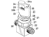
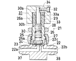
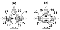
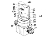
流体制御器(21)は、流体流入通路(22a)、流体流出通路(22b)および上方に向かって開口した凹所(22c)を有している直方体ブロック状本体(22)と、流体流入通路(22a)の周縁に設けられた環状弁座(23)と、環状弁座(23)に押圧または離間されて流体通路(22a)を開閉するダイヤフラム(弁体)(24)と、ダイヤフラム(24)を押さえる上下移動可能な押さえ部(25a)が下端に取り付けられた上下移動可能なディスク(弁体押さえ)(25)と、本体(22)の凹所(22c)に下端部が挿入されて上方にのびる円筒状ボンネット(26)と、本体(22)の凹所(22c)外周に設けられたおねじ部にねじ合わされボンネット(26)を本体(22)に固定する袋ナット(27)と、袋ナット(27)よりも上方にあるボンネット(26)のおねじ部にねじ合わされたナット(28)と、ボンネット(26)上端部に回転不可能に取り付けられた円筒状カバー(29)と、ボンネット(26)内に上下移動自在に挿入され下端が弁体押さえ(25)に当接し上端部(30a)がカバー(29)よりも上方に突出している弁棒(30)と、弁棒(30)上端部(30a)にねじ(32)で固定され回転させられることにより弁棒(30)を上下移動させる開閉ハンドル(31)とを備えている。 The fluid controller (21) includes a fluid inflow passage (22a), a fluid outflow passage (22b), and a rectangular parallelepiped block-shaped body (22) having a recess (22c) opened upward, and a fluid inflow passage. (22a), a diaphragm (valve element) (24) that is pressed or separated by the annular valve seat (23) to open and close the fluid passage (22a), and a diaphragm (24). ), A vertically movable disc (valve body retainer) (25) with a vertically movable retaining part (25a) attached to the lower end, and a lower end inserted into a recess (22c) of the main body (22). A cylindrical bonnet (26) extending upward, and a cap nut (27) screwed to a male thread provided on the outer periphery of the recess (22c) of the main body (22) to fix the bonnet (26) to the main body (22). , A nut (28) screwed onto the external thread of the bonnet (26) above the cap nut (27), and a cylinder non-rotatably mounted on the upper end of the bonnet (26) A cover (29) and a valve stem (30) that is vertically movably inserted into the hood (26), the lower end of which is in contact with the valve body retainer (25), and the upper end (30a) protrudes above the cover (29). ), And an opening / closing handle (31) that is fixed to the upper end (30a) of the valve stem (30) with a screw (32) and is rotated to move the valve stem (30) up and down.
各流体通路(22a)(22b)の開口には、おねじタイプの継手部(37)(38)が設けられている。 Male thread type joints (37) (38) are provided at the openings of the fluid passages (22a) (22b).
この実施形態では、ボンネット(26)の内周にめねじ部(26a)が設けられるとともに、弁棒(30)の中間部外周におねじ部(30b)が設けられ、これらのねじ部(26a)(30b)のねじ合わせによって、弁棒(30)が下方に移動し、弁体押さえ(25)が下方に移動させられる。 In this embodiment, a female thread (26a) is provided on the inner periphery of the bonnet (26), and a thread (30b) is provided on the outer periphery of the intermediate portion of the valve stem (30). ) (30b), the valve stem (30) moves downward, and the valve body retainer (25) moves downward.
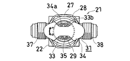
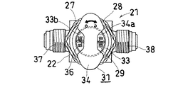
ハンドル(31)は、カバー(29)に嵌め合わせられる嵌め合わせ部(33)と、嵌め合わせ部(33)の上端に一体に設けられかつ平面から見て中央部がくびれた略長円状とされた把手部(34)とからなる。 The handle (31) has a fitting portion (33) fitted to the cover (29), and a substantially oval shape provided integrally with the upper end of the fitting portion (33) and having a center portion narrowed when viewed from a plane. Handle portion (34).
嵌め合わせ部(33)は、輪郭形状が平面から見て略長円形の筒状とされており、カバー(29)外周に対応する円筒内周面(33a)を有している。把手部(34)のくびれ部(34a)に対応する嵌め合わせ部(33)の頂壁部分は、切り欠かれており、この切欠きすなわちのぞき窓(33b)からカバー(29)の頂面が露出させられている。カバー(29)の頂面には、「OPEN」または「CLOSE」の開閉表示文字(35)(36)が90°おきに記載されている。第2実施形態の流体制御器(21)は、第1実施形態のものと同じタイプの2方弁であり、ハンドル(31)は、その長手方向が流体通路方向と一致した際には、流体通路が開に、これより90°回転させられた際(その長手方向が流体通路方向と直交するようになった際)には、流体通路が閉になるように位置決めされており、流体通路が開放されている際には、図7に示すように、カバー(29)の頂面に対向状に記載された「OPEN」の開閉表示文字(35)がハンドル(31)の把手部(34)のくびれ部(34a)から視認可能とされ、また、流体通路が閉鎖された際には、図8に示すように、カバー(29)の頂面に対向状に記載された「CLOSE」の開閉表示文字(36)がハンドル(31)の把手部(34)のくびれ部(34a)から視認可能とされている。 The fitting portion (33) has a substantially elliptical cylindrical shape when viewed from a plane, and has a cylindrical inner peripheral surface (33a) corresponding to the outer periphery of the cover (29). The top wall portion of the fitting portion (33) corresponding to the constricted portion (34a) of the handle portion (34) is notched, and the notch, that is, the top surface of the cover (29) extends from the view window (33b). It is exposed. On the top surface of the cover (29), opening / closing display characters (35) and (36) of "OPEN" or "CLOSE" are written every 90 degrees. The fluid controller (21) of the second embodiment is a two-way valve of the same type as that of the first embodiment. When the longitudinal direction of the handle (31) coincides with the direction of the fluid passage, the fluid controller (21) When the passage is opened and rotated by 90 ° from this (when its longitudinal direction is orthogonal to the fluid passage direction), the fluid passage is positioned so as to be closed, and the fluid passage is closed. When open, as shown in FIG. 7, the opening / closing display character (35) of "OPEN" written on the top surface of the cover (29) to face the handle (31) of the handle (31) When the fluid passage is closed, as shown in FIG. 8, opening and closing of “CLOSE” described on the top surface of the cover (29) in an opposing manner, as shown in FIG. The display character (36) can be visually recognized from the constriction (34a) of the handle (34) of the handle (31).
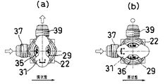
上記第2の実施形態では、制御器(21)の本体(22)は、互いに180°離れた位置に設けられた2つの流体通路(22a)(22b)開口および各開口に配管を接続するための継手部(37)(38)を有している2方弁とされているが、以下に示すように、本体(22)を直方体ブロック状のままとするとともに、内部の流体通路を変更して継手部の設置位置を変更することにより、ハンドル(31)を同じ形状として、種々の流体制御器(21)を形成することができる。なお、図9から図14までの図において、白抜きの矢印は、通路開放状態を、白丸印は、通路閉鎖状態をそれぞれ示している。 In the second embodiment, the main body (22) of the controller (21) is provided with two fluid passages (22a) and (22b) provided at positions separated by 180 ° from each other, and a pipe connected to each of the openings. It is a two-way valve having joints (37) and (38), but as shown below, the main body (22) remains in the shape of a rectangular parallelepiped block and the internal fluid passage is changed. By changing the installation position of the joint, the handle (31) can have the same shape, and various fluid controllers (21) can be formed. In FIGS. 9 to 14, white arrows indicate the passage open state, and white circles indicate the passage closed state.
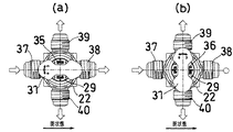
図9に示す第3実施形態は、本体(22)が互いに90°離れた位置に設けられた2つの流体通路(図示略)開口および各開口に配管を接続するための継手部(37)(39)を有しているコーナー2方弁であり、ハンドル(31)は、その長手方向が流体流入通路方向と直交した際には、流体通路が開に(図9(a)参照)、これより90°回転させられた際(その長手方向が流体通路方向と一致するようになった際)には、流体通路が閉(図9(b)参照)になるように位置決めされており、流体通路が開放されている際には、カバー(29)の頂面に対向状に記載された「OPEN」の開閉表示文字(35)がハンドル(31)の把手部(34)のくびれ部(34a)から視認可能とされ、また、流体通路が閉鎖された際には、カバー(29)の頂面に対向状に記載された「CLOSE」の開閉表示文字(36)がハンドル(31)の把手部(34)のくびれ部(34a)から視認可能とされている。 The third embodiment shown in FIG. 9 has two fluid passage (not shown) openings provided with a main body (22) separated by 90 ° from each other and joints (37) (37) for connecting a pipe to each opening. The handle (31) has a fluid passage opened when its longitudinal direction is perpendicular to the fluid inflow passage (see FIG. 9 (a)). When the fluid passage is further rotated by 90 ° (when the longitudinal direction thereof coincides with the fluid passage direction), the fluid passage is positioned so as to be closed (see FIG. 9B). When the passage is open, the opening / closing display character (35) of `` OPEN '' written opposite to the top surface of the cover (29) is indicated by the constriction (34a) of the handle (34) of the handle (31). ), And when the fluid passage is closed, the opening / closing table of “CLOSE” written on the top surface of the cover (29) in an opposite shape Character (36) is visible from the constricted portion of the grip portion (34) of the handle (31) (34a).
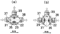
図10に示す第4実施形態、図11に示す第5実施形態および図12に示す第6実施形態は、本体(22)が3つの流体通路(図示略)開口および各開口に配管を接続するための継手部(37)(38)(39)を有している3方弁であり、3方弁の場合には、入口を基準として、入口と直角方向が閉とされて、入口と直線方向が開とされる第1の型式(図10参照)、入口と直角方向が開とされて、入口と直線方向が閉とされる第2の型式(図11参照)、入口と直角方向および直線方向がともに閉とされる第3の型式(図12参照)の3つの使用形態があり得る。第1の型式では、図10に示されているように、カバー(29)上面には、入口から時計回りに「OPEN」、「OPEN」、「OPEN」、「CLOSE」の順で開閉文字(35)(36)が表示されている。また、第2の型式では、図11に示されているように、カバー(29)上面には、入口から時計回りに「OPEN」、「OPEN」、「CLOSE」、「OPEN」の順で開閉文字(35)(36)が表示されている。第3の型式では、図12に示されているように、カバー(29)上面には、入口から時計回りに「CLOSE」、「OPEN」、「CLOSE」、「OPEN」の順で開閉文字(35)(36)が表示されている。 In the fourth embodiment shown in FIG. 10, the fifth embodiment shown in FIG. 11, and the sixth embodiment shown in FIG. 12, the main body (22) has three fluid passages (not shown) and a pipe connected to each opening. Three-way valve that has joints (37), (38), and (39) for the three-way valve. A first type in which the direction is opened (see FIG. 10), a second type in which the direction perpendicular to the inlet is opened and the straight line direction is closed (see FIG. 11), a direction perpendicular to the inlet and There can be three usages of the third type (see FIG. 12) in which both linear directions are closed. In the first type, as shown in FIG. 10, the opening and closing characters (“OPEN”, “OPEN”, “OPEN”, “CLOSE”) are formed on the upper surface of the cover (29) clockwise from the entrance. 35) and (36) are displayed. In the second model, as shown in FIG. 11, the upper surface of the cover (29) is opened and closed clockwise from the entrance in the order of "OPEN", "OPEN", "CLOSE", and "OPEN". Characters (35) and (36) are displayed. In the third type, as shown in FIG. 12, on the upper surface of the cover (29), opening and closing characters (CLOSE), "OPEN", "CLOSE", and "OPEN" are clockwise from the entrance. 35) and (36) are displayed.
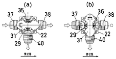
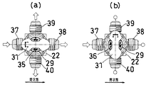
図13に示す第7実施形態および図14に示す第8実施形態は、本体(22)が互いに90°離れた位置に設けられた4つの流体通路(図示略)開口および各開口に配管を接続するための継手部(37)(38)(39)(40)を有している4方弁であり、4方弁の場合には、3つの出口がすべて閉とされる第1の型式(図13参照)、入口から見て右の方向および左の方向が閉とされて、入口から見て真っ直ぐの方向が開とされる第2の型式(図14参照)、入口から見て左右の方向がいずれも閉とされて、入口から見て真っ直ぐの方向が開とされる第3の型式(図示略)、入口から見て左の方向および真っ直ぐの方向がいずれも閉とされて、入口から見て右の方向が開とされる第4の型式(図示略)などの使用形態があり得る。第1の型式では、図13に示されているように、カバー(29)上面には、入口から時計回りに「CLOSE」、「OPEN」、「CLOSE」、「OPEN」の順で開閉文字(35)(36)が表示さていれる。また、第2の型式では、図14に示されているように、カバー(29)上面には、入口から時計回りに「OPEN」、「OPEN」、「CLOSE」、「OPEN」の順で開閉文字(35)(36)が表示されている。第1および第2以外の型式については、同様に、カバー(29)上面に90°おきに、開表示「OPEN」(35)および閉表示「CLOSE」(36)のいずれか一方が施される。 In the seventh embodiment shown in FIG. 13 and the eighth embodiment shown in FIG. 14, the body (22) is provided with four fluid passages (not shown) provided at positions separated from each other by 90 °, and a pipe is connected to each of the openings. Valve having a joint portion (37), (38), (39), (40), and in the case of a four-way valve, a first type in which all three outlets are closed ( A second type (see FIG. 13) in which the right and left directions as viewed from the entrance are closed and the straight direction as viewed from the entrance is opened (see FIG. 14). A third type (not shown) in which both directions are closed and a straight direction is opened when viewed from the entrance, and both a left direction and a straight direction when viewed from the entrance are closed and the entrance is opened. There is a use form such as a fourth type (not shown) in which the right direction is opened when viewed from the side. In the first type, as shown in FIG. 13, the opening and closing characters (“CLOSE”, “OPEN”, “CLOSE”, “OPEN”) are arranged on the upper surface of the cover (29) clockwise from the entrance. 35) and (36) are displayed. In the second model, as shown in FIG. 14, the upper surface of the cover (29) is opened and closed clockwise from the entrance in the order of "OPEN", "OPEN", "CLOSE", "OPEN". Characters (35) and (36) are displayed. Similarly, for the models other than the first and second models, one of the open indication “OPEN” (35) and the closed indication “CLOSE” (36) is provided at 90 ° intervals on the top surface of the cover (29). .
図15から図17までは、この発明の流体制御器の第9実施形態を示している。図15および図16は、流体通路が開放された状態、図17は、流体通路が閉鎖された状態をそれぞれ示している。 FIGS. 15 to 17 show a ninth embodiment of the fluid controller of the present invention. 15 and 16 show a state in which the fluid passage is opened, and FIG. 17 shows a state in which the fluid passage is closed.
この実施形態は、図5から図8までに示した第2実施形態に対し、ハンドルの構成が異なるだけであり、第2実施形態と同じものには同じ符号を付してその説明を省略する。 This embodiment differs from the second embodiment shown in FIGS. 5 to 8 only in the configuration of the handle, and the same components as those in the second embodiment are denoted by the same reference numerals and description thereof is omitted. .
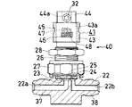
ハンドル(41)は、カバー(29)に嵌め合わせられる嵌め合わせ部(43)と、嵌め合わせ部(43)の上端に一体に設けられかつ平面から見て中央部がくびれた略長円状とされた把手部(44)とからなる。 The handle (41) has a fitting portion (43) fitted to the cover (29), and a substantially oval shape provided integrally with the upper end of the fitting portion (43) and having a central portion narrowed when viewed from a plane. Handle part (44).
嵌め合わせ部(43)は、輪郭形状が平面から見て略長円形の筒状とされており、カバー(29)外周に対応する円筒内周面(43a)を有している。把手部(44)のくびれ部(44a)に対応する嵌め合わせ部(43)の頂壁部分は、切り欠かれており、この切欠きすなわちのぞき窓(43b)からカバー(29)の頂面が露出させられている。カバー(29)の頂面には、「OPEN」または「CLOSE」の開閉表示文字(35)(36)が90°おきに記載されている。ハンドル(41)の嵌め合わせ部(43)の周壁には、側面のぞき窓(45)(46)が設けられており、これに対応するように、カバー部(29)の周面には、のぞき窓(45)(46)から視認可能な開閉表示文字(47)(48)が記載されている。のぞき窓は、90°おきに全部で4つ設けられており、180°離れたもの同士が同じ高さとされ、90°離れたもの同士は異なる高さとされている。高さが高い方が「OPEN」(47)の表示用、高さが低い方が「CLOSE」(48)の表示用とされている。高さの差は、ボンネット(26)のめねじ部(26a)および弁棒(30)のおねじ部(30b)のピッチの1/4とされている。 The fitting portion (43) has a substantially elliptical cylindrical shape when viewed from a plane, and has a cylindrical inner peripheral surface (43a) corresponding to the outer periphery of the cover (29). The top wall portion of the fitting portion (43) corresponding to the constricted portion (44a) of the handle portion (44) is notched, and the notch, that is, the top surface of the cover (29) extends from the view window (43b). It is exposed. On the top surface of the cover (29), opening / closing display characters (35) and (36) of "OPEN" or "CLOSE" are written every 90 degrees. Side view windows (45) and (46) are provided on the peripheral wall of the fitting portion (43) of the handle (41), and correspondingly, the peripheral surface of the cover (29) is Opening / closing display characters (47) and (48) visible from the windows (45) and (46) are described. A total of four viewing windows are provided at intervals of 90 °, and those that are 180 ° apart have the same height, and those that are 90 ° apart have different heights. The higher height is used for displaying "OPEN" (47), and the lower height is used for displaying "CLOSE" (48). The difference in height is set to 4 of the pitch between the female thread (26a) of the bonnet (26) and the male thread (30b) of the valve stem (30).
ハンドル(41)は、その長手方向が流体通路方向と一致した際には、流体通路が開に、これより90°回転させられた際(その長手方向が流体通路方向と直交するようになった際)には、流体通路が閉になるように位置決めされており、流体通路が開放されている際には、図15および図16に示すように、カバー(29)の頂面に対向状に記載された「OPEN」の開閉表示文字(47)がハンドル(41)の把手部(44)のくびれ部(44a)から視認可能とされるとともに、嵌め合わせ部(44)の周壁に設けられた側面のぞき窓(45)からも「OPEN」の開閉表示文字(47)が視認可能とされている。そして、この位置から、ハンドル(41)を90°回転させると、ハンドル(41)はカバー(29)に対して回転しながら下方に移動し、これにより、流体通路が閉鎖され、この際、カバー(29)の頂面に対向状に記載された「CLOSE」の開閉表示文字(図には現れず)がハンドル(41)の把手部(44)のくびれ部(44a)から視認可能とされるとともに、図17に示すように、嵌め合わせ部(44)の周壁に設けられた側面のぞき窓(46)からも「CLOSE」の開閉表示文字(48)が視認可能とされている。 When the handle (41) has its longitudinal direction coinciding with the fluid passage direction, the fluid passage is opened, and when the handle (41) is rotated by 90 ° (the longitudinal direction is perpendicular to the fluid passage direction). 15), the fluid passage is positioned so as to be closed. When the fluid passage is open, as shown in FIGS. 15 and 16, the fluid passage is opposed to the top surface of the cover (29). The described opening / closing display character (47) of "OPEN" is made visible from the constricted portion (44a) of the handle portion (44) of the handle (41) and is provided on the peripheral wall of the fitting portion (44). The opening / closing display character (47) of "OPEN" is also visible from the side view window (45). Then, when the handle (41) is rotated 90 ° from this position, the handle (41) moves downward while rotating with respect to the cover (29), thereby closing the fluid passage. Opening / closing characters of "CLOSE" (not shown in the figure) written on the top surface of (29) in opposition are visible from the constricted portion (44a) of the handle (44) of the handle (41). At the same time, as shown in FIG. 17, the opening / closing display character (48) of "CLOSE" can be visually recognized from the side view window (46) provided on the peripheral wall of the fitting portion (44).
この第9実施形態の流体制御器(40)によると、その開閉状態を上からも横からも確認することができるので、多数の流体制御器によって構成されている流体制御装置での開閉表示確認をより容易に行うことができる。第9実施形態の流体制御器(40)についても、図9から図14までに示した形態とできるのはもちろんである。 According to the fluid controller (40) of the ninth embodiment, the open / closed state of the fluid controller can be confirmed from above and from the side. Can be performed more easily. It goes without saying that the fluid controller (40) of the ninth embodiment can also take the forms shown in FIGS.
上記各実施形態においては、継手部(37)(38)(39)(40)の形状がおねじとされているが、継手部の形状は、おねじに限られるものではなく、公知の種々の継手部構造に変更することができる。 In each of the above embodiments, the shapes of the joints (37), (38), (39), and (40) are male threads. Can be changed to the joint structure.
また、ハンドルを90°回転させた際に通路を遮断開放状態するための構成は、特に限定されるものでなく、例えば、第2実施形態以降のものにおいて、その遮断開放機構を第1実施形態のものに置き換えてももちろんよく、また、各実施形態のものにおいて、上記以外の種々の遮断開放機構を採用することもできる。 The structure for opening and closing the passage when the handle is turned by 90 ° is not particularly limited. For example, in the second and subsequent embodiments, the opening and closing mechanism is changed to the first embodiment. It is a matter of course that it may be replaced with the above-described one, and in each embodiment, various blocking / opening mechanisms other than those described above may be employed.
(1) 流体制御器
(2) 本体
(2a)(2b) 流体通路
(6) ボンネット
(8) カバー
(9) 弁棒
(10) ハンドル
(10a) くびれ部
(18)(19) 開閉表示文字
(21) 流体制御器
(22) 本体
(22a)(22b)流体通路
(26) ボンネット
(29) カバー
(30) 弁棒
(31) ハンドル
(33) 嵌め合わせ部
(34) 把手部
(34a) くびれ部
(35)(36) 開閉表示文字
(37)(38) 継手部
(39)(40) 継手部
(45)(46) 側面のぞき窓
(47)(48) 開閉表示文字
(1) Fluid controller
(2) Main unit
(2a) (2b) Fluid passage
(6) Bonnet
(8) Cover
(9) Valve stem
(10) Handle
(10a) Constriction
(18) (19) Open / close indication characters
(21) Fluid controller
(22) Main unit
(22a) (22b) Fluid passage
(26) Bonnet
(29) Cover
(30) Valve stem
(31) Handle
(33) Fitting part
(34) Handle
(34a) Constriction
(35) (36) Open / close indication characters
(37) (38) Joint part
(39) (40) Joint part
(45) (46) Side view window
(47) (48) Open / close indication characters
Claims (8)
Priority Applications (1)
| Application Number | Priority Date | Filing Date | Title |
|---|---|---|---|
| JP2003271267A JP4599813B2 (en) | 2002-11-28 | 2003-07-07 | Fluid controller |
Applications Claiming Priority (2)
| Application Number | Priority Date | Filing Date | Title |
|---|---|---|---|
| JP2002344870 | 2002-11-28 | ||
| JP2003271267A JP4599813B2 (en) | 2002-11-28 | 2003-07-07 | Fluid controller |
Publications (2)
| Publication Number | Publication Date |
|---|---|
| JP2004190852A true JP2004190852A (en) | 2004-07-08 |
| JP4599813B2 JP4599813B2 (en) | 2010-12-15 |
Family
ID=32774838
Family Applications (1)
| Application Number | Title | Priority Date | Filing Date |
|---|---|---|---|
| JP2003271267A Expired - Lifetime JP4599813B2 (en) | 2002-11-28 | 2003-07-07 | Fluid controller |
Country Status (1)
| Country | Link |
|---|---|
| JP (1) | JP4599813B2 (en) |
Cited By (1)
| Publication number | Priority date | Publication date | Assignee | Title |
|---|---|---|---|---|
| JP2016121775A (en) * | 2014-12-25 | 2016-07-07 | 株式会社フジキン | Fluid controller |
Citations (7)
| Publication number | Priority date | Publication date | Assignee | Title |
|---|---|---|---|---|
| JPS49151123U (en) * | 1973-04-27 | 1974-12-27 | ||
| JPS5635957U (en) * | 1979-08-30 | 1981-04-07 | ||
| JPS56147977A (en) * | 1980-04-19 | 1981-11-17 | Kyowa Sangyo:Kk | Automatic switching-valve |
| JPS57143462U (en) * | 1981-03-05 | 1982-09-08 | ||
| JPH0575576U (en) * | 1992-03-13 | 1993-10-15 | 株式会社大東バルブ製作所 | valve |
| JPH06241331A (en) * | 1993-02-18 | 1994-08-30 | Motoyama Seisakusho:Kk | Hand valve device |
| JPH07280134A (en) * | 1994-04-08 | 1995-10-27 | Neriki:Kk | Valve with open/close indicator device |
-
2003
- 2003-07-07 JP JP2003271267A patent/JP4599813B2/en not_active Expired - Lifetime
Patent Citations (7)
| Publication number | Priority date | Publication date | Assignee | Title |
|---|---|---|---|---|
| JPS49151123U (en) * | 1973-04-27 | 1974-12-27 | ||
| JPS5635957U (en) * | 1979-08-30 | 1981-04-07 | ||
| JPS56147977A (en) * | 1980-04-19 | 1981-11-17 | Kyowa Sangyo:Kk | Automatic switching-valve |
| JPS57143462U (en) * | 1981-03-05 | 1982-09-08 | ||
| JPH0575576U (en) * | 1992-03-13 | 1993-10-15 | 株式会社大東バルブ製作所 | valve |
| JPH06241331A (en) * | 1993-02-18 | 1994-08-30 | Motoyama Seisakusho:Kk | Hand valve device |
| JPH07280134A (en) * | 1994-04-08 | 1995-10-27 | Neriki:Kk | Valve with open/close indicator device |
Cited By (1)
| Publication number | Priority date | Publication date | Assignee | Title |
|---|---|---|---|---|
| JP2016121775A (en) * | 2014-12-25 | 2016-07-07 | 株式会社フジキン | Fluid controller |
Also Published As
| Publication number | Publication date |
|---|---|
| JP4599813B2 (en) | 2010-12-15 |
Similar Documents
| Publication | Publication Date | Title |
|---|---|---|
| KR900000624A (en) | Fluid control valve | |
| EP0247347B1 (en) | Fluid flow control valve | |
| KR200478984Y1 (en) | Cryogenic globe valve | |
| JP3861206B2 (en) | Fluid controller | |
| JP5613420B2 (en) | Fluid controller | |
| JP6371404B2 (en) | Ball valve | |
| JP2012002355A (en) | Rotary valve | |
| JP6580377B2 (en) | Valve with locking mechanism and integrated valve | |
| US20060278280A1 (en) | Check valve | |
| JP2004190852A (en) | Fluid controller | |
| KR101180126B1 (en) | Safety Valve Unit | |
| JPH0942489A (en) | Ball valve having check valve | |
| WO2007145558A1 (en) | Child-protecting safety capsule | |
| CN220102109U (en) | Drain valve | |
| US20110100756A1 (en) | Oil Drain Connector Structure for Marine Filter | |
| JP5016905B2 (en) | Metal seat butterfly valve | |
| KR101118271B1 (en) | Bellows globe valve | |
| JP2010261466A (en) | Gas cock | |
| GB2062810A (en) | On-off spring valve for fluids | |
| JP5094629B2 (en) | Stopcock | |
| JP5988635B2 (en) | valve | |
| US995027A (en) | Handle for cocks, faucets, and valves. | |
| KR200199729Y1 (en) | A ball valve having a type of flange shape | |
| KR101186131B1 (en) | A gate valve | |
| KR200264338Y1 (en) | slide type gate valve for pipe |
Legal Events
| Date | Code | Title | Description |
|---|---|---|---|
| A621 | Written request for application examination |
Free format text: JAPANESE INTERMEDIATE CODE: A621 Effective date: 20060426 |
|
| A977 | Report on retrieval |
Free format text: JAPANESE INTERMEDIATE CODE: A971007 Effective date: 20090205 |
|
| A131 | Notification of reasons for refusal |
Free format text: JAPANESE INTERMEDIATE CODE: A131 Effective date: 20090224 |
|
| A521 | Request for written amendment filed |
Free format text: JAPANESE INTERMEDIATE CODE: A523 Effective date: 20090423 |
|
| A02 | Decision of refusal |
Free format text: JAPANESE INTERMEDIATE CODE: A02 Effective date: 20091027 |
|
| A521 | Request for written amendment filed |
Free format text: JAPANESE INTERMEDIATE CODE: A523 Effective date: 20100125 |
|
| A911 | Transfer to examiner for re-examination before appeal (zenchi) |
Free format text: JAPANESE INTERMEDIATE CODE: A911 Effective date: 20100128 |
|
| A131 | Notification of reasons for refusal |
Free format text: JAPANESE INTERMEDIATE CODE: A131 Effective date: 20100511 |
|
| A521 | Request for written amendment filed |
Free format text: JAPANESE INTERMEDIATE CODE: A523 Effective date: 20100709 |
|
| TRDD | Decision of grant or rejection written | ||
| A01 | Written decision to grant a patent or to grant a registration (utility model) |
Free format text: JAPANESE INTERMEDIATE CODE: A01 Effective date: 20100817 |
|
| A01 | Written decision to grant a patent or to grant a registration (utility model) |
Free format text: JAPANESE INTERMEDIATE CODE: A01 |
|
| A61 | First payment of annual fees (during grant procedure) |
Free format text: JAPANESE INTERMEDIATE CODE: A61 Effective date: 20100913 |
|
| FPAY | Renewal fee payment (event date is renewal date of database) |
Free format text: PAYMENT UNTIL: 20131008 Year of fee payment: 3 |
|
| R150 | Certificate of patent or registration of utility model |
Ref document number: 4599813 Country of ref document: JP Free format text: JAPANESE INTERMEDIATE CODE: R150 Free format text: JAPANESE INTERMEDIATE CODE: R150 |
|
| R250 | Receipt of annual fees |
Free format text: JAPANESE INTERMEDIATE CODE: R250 |
|
| R250 | Receipt of annual fees |
Free format text: JAPANESE INTERMEDIATE CODE: R250 |
|
| R250 | Receipt of annual fees |
Free format text: JAPANESE INTERMEDIATE CODE: R250 |
|
| R250 | Receipt of annual fees |
Free format text: JAPANESE INTERMEDIATE CODE: R250 |
|
| R250 | Receipt of annual fees |
Free format text: JAPANESE INTERMEDIATE CODE: R250 |
|
| R250 | Receipt of annual fees |
Free format text: JAPANESE INTERMEDIATE CODE: R250 |
|
| R250 | Receipt of annual fees |
Free format text: JAPANESE INTERMEDIATE CODE: R250 |
|
| R250 | Receipt of annual fees |
Free format text: JAPANESE INTERMEDIATE CODE: R250 |
|
| R250 | Receipt of annual fees |
Free format text: JAPANESE INTERMEDIATE CODE: R250 |
|
| R250 | Receipt of annual fees |
Free format text: JAPANESE INTERMEDIATE CODE: R250 |
|
| EXPY | Cancellation because of completion of term |