JP2004190860A - valve - Google Patents
valve Download PDFInfo
- Publication number
- JP2004190860A JP2004190860A JP2003420343A JP2003420343A JP2004190860A JP 2004190860 A JP2004190860 A JP 2004190860A JP 2003420343 A JP2003420343 A JP 2003420343A JP 2003420343 A JP2003420343 A JP 2003420343A JP 2004190860 A JP2004190860 A JP 2004190860A
- Authority
- JP
- Japan
- Prior art keywords
- sample
- valve
- conduit
- container
- orifice
- Prior art date
- Legal status (The legal status is an assumption and is not a legal conclusion. Google has not performed a legal analysis and makes no representation as to the accuracy of the status listed.)
- Pending
Links
- 238000004140 cleaning Methods 0.000 abstract description 31
- 239000000463 material Substances 0.000 abstract description 22
- 238000007789 sealing Methods 0.000 abstract description 21
- 238000011109 contamination Methods 0.000 abstract description 12
- XLYOFNOQVPJJNP-UHFFFAOYSA-N water Chemical compound O XLYOFNOQVPJJNP-UHFFFAOYSA-N 0.000 abstract description 12
- 239000000126 substance Substances 0.000 abstract description 8
- 238000000605 extraction Methods 0.000 abstract description 7
- 238000010586 diagram Methods 0.000 abstract description 3
- 239000012530 fluid Substances 0.000 abstract 2
- 239000000523 sample Substances 0.000 description 136
- 238000000034 method Methods 0.000 description 31
- 238000005070 sampling Methods 0.000 description 27
- 230000008569 process Effects 0.000 description 22
- 238000013461 design Methods 0.000 description 16
- 238000010899 nucleation Methods 0.000 description 8
- 238000009825 accumulation Methods 0.000 description 7
- 238000001514 detection method Methods 0.000 description 7
- 239000011538 cleaning material Substances 0.000 description 5
- 238000005259 measurement Methods 0.000 description 5
- 238000012986 modification Methods 0.000 description 5
- 230000004048 modification Effects 0.000 description 5
- 230000001954 sterilising effect Effects 0.000 description 5
- 239000000356 contaminant Substances 0.000 description 4
- 239000002184 metal Substances 0.000 description 4
- 238000004659 sterilization and disinfection Methods 0.000 description 4
- 238000012795 verification Methods 0.000 description 4
- 230000008859 change Effects 0.000 description 3
- 239000003599 detergent Substances 0.000 description 3
- 230000009969 flowable effect Effects 0.000 description 3
- 239000002245 particle Substances 0.000 description 3
- 230000029058 respiratory gaseous exchange Effects 0.000 description 3
- 238000009331 sowing Methods 0.000 description 3
- 238000012360 testing method Methods 0.000 description 3
- 230000002378 acidificating effect Effects 0.000 description 2
- 230000004888 barrier function Effects 0.000 description 2
- 239000012459 cleaning agent Substances 0.000 description 2
- 230000008878 coupling Effects 0.000 description 2
- 238000010168 coupling process Methods 0.000 description 2
- 238000005859 coupling reaction Methods 0.000 description 2
- 238000012423 maintenance Methods 0.000 description 2
- 230000007246 mechanism Effects 0.000 description 2
- 238000011176 pooling Methods 0.000 description 2
- 238000004886 process control Methods 0.000 description 2
- 239000000047 product Substances 0.000 description 2
- 239000002699 waste material Substances 0.000 description 2
- 230000037303 wrinkles Effects 0.000 description 2
- LFQSCWFLJHTTHZ-UHFFFAOYSA-N Ethanol Chemical compound CCO LFQSCWFLJHTTHZ-UHFFFAOYSA-N 0.000 description 1
- 230000002159 abnormal effect Effects 0.000 description 1
- 230000009471 action Effects 0.000 description 1
- 230000003213 activating effect Effects 0.000 description 1
- 150000001298 alcohols Chemical class 0.000 description 1
- 238000004458 analytical method Methods 0.000 description 1
- 239000006227 byproduct Substances 0.000 description 1
- 238000004113 cell culture Methods 0.000 description 1
- 239000007795 chemical reaction product Substances 0.000 description 1
- 239000003251 chemically resistant material Substances 0.000 description 1
- 238000007596 consolidation process Methods 0.000 description 1
- 238000010276 construction Methods 0.000 description 1
- 238000009826 distribution Methods 0.000 description 1
- 238000005516 engineering process Methods 0.000 description 1
- 230000007717 exclusion Effects 0.000 description 1
- 238000000855 fermentation Methods 0.000 description 1
- 230000004151 fermentation Effects 0.000 description 1
- 238000011010 flushing procedure Methods 0.000 description 1
- 230000005484 gravity Effects 0.000 description 1
- 230000007257 malfunction Effects 0.000 description 1
- 238000000691 measurement method Methods 0.000 description 1
- 239000013618 particulate matter Substances 0.000 description 1
- 230000000149 penetrating effect Effects 0.000 description 1
- 230000035515 penetration Effects 0.000 description 1
- 230000002093 peripheral effect Effects 0.000 description 1
- 238000003825 pressing Methods 0.000 description 1
- 230000009290 primary effect Effects 0.000 description 1
- 238000003672 processing method Methods 0.000 description 1
- 238000010926 purge Methods 0.000 description 1
- 238000012958 reprocessing Methods 0.000 description 1
- 238000012827 research and development Methods 0.000 description 1
- 238000007142 ring opening reaction Methods 0.000 description 1
- 238000012163 sequencing technique Methods 0.000 description 1
- 239000003206 sterilizing agent Substances 0.000 description 1
- 239000008400 supply water Substances 0.000 description 1
- 238000005406 washing Methods 0.000 description 1
Images


Classifications
-
- F—MECHANICAL ENGINEERING; LIGHTING; HEATING; WEAPONS; BLASTING
- F16—ENGINEERING ELEMENTS AND UNITS; GENERAL MEASURES FOR PRODUCING AND MAINTAINING EFFECTIVE FUNCTIONING OF MACHINES OR INSTALLATIONS; THERMAL INSULATION IN GENERAL
- F16K—VALVES; TAPS; COCKS; ACTUATING-FLOATS; DEVICES FOR VENTING OR AERATING
- F16K41/00—Spindle sealings
- F16K41/10—Spindle sealings with diaphragm, e.g. shaped as bellows or tube
- F16K41/103—Spindle sealings with diaphragm, e.g. shaped as bellows or tube the diaphragm and the closure member being integrated in one member
-
- C—CHEMISTRY; METALLURGY
- C12—BIOCHEMISTRY; BEER; SPIRITS; WINE; VINEGAR; MICROBIOLOGY; ENZYMOLOGY; MUTATION OR GENETIC ENGINEERING
- C12M—APPARATUS FOR ENZYMOLOGY OR MICROBIOLOGY; APPARATUS FOR CULTURING MICROORGANISMS FOR PRODUCING BIOMASS, FOR GROWING CELLS OR FOR OBTAINING FERMENTATION OR METABOLIC PRODUCTS, i.e. BIOREACTORS OR FERMENTERS
- C12M33/00—Means for introduction, transport, positioning, extraction, harvesting, peeling or sampling of biological material in or from the apparatus
- C12M33/04—Means for introduction, transport, positioning, extraction, harvesting, peeling or sampling of biological material in or from the apparatus by injection or suction, e.g. using pipettes, syringes, needles
-
- G—PHYSICS
- G01—MEASURING; TESTING
- G01N—INVESTIGATING OR ANALYSING MATERIALS BY DETERMINING THEIR CHEMICAL OR PHYSICAL PROPERTIES
- G01N1/00—Sampling; Preparing specimens for investigation
- G01N1/02—Devices for withdrawing samples
- G01N1/10—Devices for withdrawing samples in the liquid or fluent state
- G01N1/20—Devices for withdrawing samples in the liquid or fluent state for flowing or falling materials
- G01N1/2035—Devices for withdrawing samples in the liquid or fluent state for flowing or falling materials by deviating part of a fluid stream, e.g. by drawing-off or tapping
-
- G—PHYSICS
- G01—MEASURING; TESTING
- G01N—INVESTIGATING OR ANALYSING MATERIALS BY DETERMINING THEIR CHEMICAL OR PHYSICAL PROPERTIES
- G01N1/00—Sampling; Preparing specimens for investigation
- G01N1/02—Devices for withdrawing samples
- G01N1/10—Devices for withdrawing samples in the liquid or fluent state
- G01N2001/1006—Dispersed solids
- G01N2001/1012—Suspensions
-
- G—PHYSICS
- G01—MEASURING; TESTING
- G01N—INVESTIGATING OR ANALYSING MATERIALS BY DETERMINING THEIR CHEMICAL OR PHYSICAL PROPERTIES
- G01N1/00—Sampling; Preparing specimens for investigation
- G01N1/02—Devices for withdrawing samples
- G01N1/10—Devices for withdrawing samples in the liquid or fluent state
- G01N1/14—Suction devices, e.g. pumps; Ejector devices
- G01N2001/1445—Overpressure, pressurisation at sampling point
-
- G—PHYSICS
- G01—MEASURING; TESTING
- G01N—INVESTIGATING OR ANALYSING MATERIALS BY DETERMINING THEIR CHEMICAL OR PHYSICAL PROPERTIES
- G01N1/00—Sampling; Preparing specimens for investigation
- G01N1/02—Devices for withdrawing samples
- G01N1/10—Devices for withdrawing samples in the liquid or fluent state
- G01N1/20—Devices for withdrawing samples in the liquid or fluent state for flowing or falling materials
- G01N1/2035—Devices for withdrawing samples in the liquid or fluent state for flowing or falling materials by deviating part of a fluid stream, e.g. by drawing-off or tapping
- G01N2001/205—Devices for withdrawing samples in the liquid or fluent state for flowing or falling materials by deviating part of a fluid stream, e.g. by drawing-off or tapping using a valve
-
- Y—GENERAL TAGGING OF NEW TECHNOLOGICAL DEVELOPMENTS; GENERAL TAGGING OF CROSS-SECTIONAL TECHNOLOGIES SPANNING OVER SEVERAL SECTIONS OF THE IPC; TECHNICAL SUBJECTS COVERED BY FORMER USPC CROSS-REFERENCE ART COLLECTIONS [XRACs] AND DIGESTS
- Y10—TECHNICAL SUBJECTS COVERED BY FORMER USPC
- Y10T—TECHNICAL SUBJECTS COVERED BY FORMER US CLASSIFICATION
- Y10T137/00—Fluid handling
- Y10T137/4238—With cleaner, lubrication added to fluid or liquid sealing at valve interface
- Y10T137/4245—Cleaning or steam sterilizing
- Y10T137/4259—With separate material addition
-
- Y—GENERAL TAGGING OF NEW TECHNOLOGICAL DEVELOPMENTS; GENERAL TAGGING OF CROSS-SECTIONAL TECHNOLOGIES SPANNING OVER SEVERAL SECTIONS OF THE IPC; TECHNICAL SUBJECTS COVERED BY FORMER USPC CROSS-REFERENCE ART COLLECTIONS [XRACs] AND DIGESTS
- Y10—TECHNICAL SUBJECTS COVERED BY FORMER USPC
- Y10T—TECHNICAL SUBJECTS COVERED BY FORMER US CLASSIFICATION
- Y10T137/00—Fluid handling
- Y10T137/4238—With cleaner, lubrication added to fluid or liquid sealing at valve interface
- Y10T137/4245—Cleaning or steam sterilizing
- Y10T137/4266—Steam sterilizing
Landscapes
- Life Sciences & Earth Sciences (AREA)
- Health & Medical Sciences (AREA)
- Engineering & Computer Science (AREA)
- General Engineering & Computer Science (AREA)
- Chemical & Material Sciences (AREA)
- Zoology (AREA)
- Bioinformatics & Cheminformatics (AREA)
- Organic Chemistry (AREA)
- Wood Science & Technology (AREA)
- Biochemistry (AREA)
- General Health & Medical Sciences (AREA)
- Biomedical Technology (AREA)
- Analytical Chemistry (AREA)
- Pathology (AREA)
- Molecular Biology (AREA)
- General Physics & Mathematics (AREA)
- Physics & Mathematics (AREA)
- Biotechnology (AREA)
- Microbiology (AREA)
- Sustainable Development (AREA)
- Immunology (AREA)
- Mechanical Engineering (AREA)
- Genetics & Genomics (AREA)
- Hydrology & Water Resources (AREA)
- Sampling And Sample Adjustment (AREA)
- Apparatus Associated With Microorganisms And Enzymes (AREA)
- Valve Housings (AREA)
- Details Of Valves (AREA)
Abstract
【課題】流動性物質である試料を容器または導管(播種装置)内に移動させるか、あるいは流動性物質である試料を容器または導管(試料抽出装置)から移動させる。
【解決手段】装置Aは容器または導管から試料を抜き出し、あるいはこの容器または導管に対し試料を供給することが出来る。この装置は入口流路12およびドレン流路14を備えた本体10を包含し、両流路は本体に対し傾斜している。可撓性蛇腹30は本体の内部腔3内に配置されている。蛇腹のシーリング尖端32は弁作動ロッド22により可動であって、本体内の試料腔11へのオリフィス33を閉じる。入口流路を経由して水蒸気5、純粋乾燥空気6および/または洗浄媒質7を供給して、装置のひびを清掃し、かつ装置内で移動パーツの露出を回避して、試料の汚染を回避することが出来る。
【選択図】 図1A sample, which is a fluid substance, is moved into a container or a conduit (seed device), or a sample, which is a fluid material, is moved from a container or a conduit (sample extraction device).
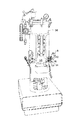
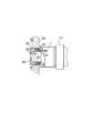
Apparatus A can withdraw a sample from a container or conduit or supply a sample to the container or conduit. The device includes a body 10 having an inlet channel 12 and a drain channel 14, both channels being inclined relative to the body. A flexible bellows 30 is located in the interior cavity 3 of the body. The bellows sealing tip 32 is movable by the valve actuation rod 22 and closes the orifice 33 to the sample cavity 11 in the body. Water vapor 5, pure dry air 6 and / or cleaning medium 7 are supplied via the inlet channel to clean the device cracks and avoid exposure of moving parts in the device to avoid sample contamination. You can do it.
[Selection diagram] Fig. 1
Description
本発明は、弁に関し、例えば、容器または導管のための自動化された試料抽出装置または供給装置/播種装置における弁に関する。この容器または導管はバイオリアクターまたはその他の類似装置であってよい。 The present invention relates to valves, for example, valves in automated sample extraction devices or supply / seed devices for containers or conduits. This vessel or conduit may be a bioreactor or other similar device.
現存する製品の、新しいあるいは一層効率的な工業化についての発展はプロセス変数を測定するためのより迅速、かつより効果的な方法を必要としている。バイオリアクター中で行われる細胞培養および発酵において、このことは特に真実であり、そこではリサーチおよび開発における測定値の精度が、高純度であって、高度に精製された最終生成物を得るためには臨界的である。 The evolution of existing products for new or more efficient industrialization requires faster and more effective methods for measuring process variables. This is especially true in cell cultures and fermentations performed in bioreactors, where the accuracy of the measurements in research and development is high in order to obtain highly pure and highly purified end products. Is critical.
制御せねばならない或る種のファクターには温度および圧力がある。これらのファクターは標準のセンサーを利用して容易に測定される。しかし、数多くの他のファクターは外部の実験室分析用の試料を取出すことによってのみ測定可能である。試験および測定のための試料抽出の頻度、すなわち各試料についての試験回数およびプロセスについての時間の拘束は、試料を得るために用いる方法および装置と同様に広範囲に変化する。 Certain factors that must be controlled include temperature and pressure. These factors are easily measured using standard sensors. However, many other factors can only be measured by removing a sample for external laboratory analysis. The frequency of sample extraction for testing and measurement, i.e., the number of tests for each sample and the time constraints on the process, vary widely, as well as the methods and equipment used to obtain the samples.
殆どの場合、変数のための測定方法はその方法において直接リモートセンサーによる現場での測定をもたらすものではなく、むしろ試料はその方法から物理的に抽出され、そして容器または導管の外部で試験かつ処理されねばならない。この試験および処理方法が手動または自動化いずれかの態様において有効に遂行される以前に試料抽出の安全、有効な手段が利用出来なければならない。このサンプリング工程はプロセス組成物の精確な副試料である生成物を提供せねばならない。更に、従来技術による設計は現存システムにおける使用に適合しないので、そのシステムに対する可成りの変更を要する。この装置は、工業的応用に関して有用性をもたらすために良質で、再現性ある結果を提供する一方、効率的かつ費用効果のある方法においてサンプリング工程に関連する危険を最小とするか、排除することが必要とされる。 In most cases, the measurement method for the variables does not directly result in the field measurement by a remote sensor in the method, but rather the sample is physically extracted from the method and tested and processed outside the container or conduit. Must be done. Before this test and processing method can be effectively performed in either a manual or automated manner, a safe and effective means of sample extraction must be available. This sampling step must provide a product that is an accurate subsample of the process composition. In addition, prior art designs are not compatible with use in existing systems and require significant changes to that system. This device should provide high quality and reproducible results to provide utility for industrial applications, while minimizing or eliminating the risks associated with the sampling process in an efficient and cost-effective manner Is required.
回避されねばならない一つの危険はオペレータまたは環境に対する危険である。試料、特に危険な試料をもって作業する場合、方法の全体性、引続く試料、そのオペレータまたはその外部環境を危険にさらすことなく、試料を取出し、または供給/播種することが必要である。数多くの従来技術による装置はこの領域において不満足である。 One danger that must be avoided is a danger to the operator or the environment. When working with samples, especially dangerous samples, it is necessary to remove or feed / seed the sample without jeopardizing the integrity of the method, the subsequent sample, its operator or its external environment. Many prior art devices are unsatisfactory in this area.
更に、或る種の従来技術システムは自動化されていない。それ故、そこには人間の処置上のエラーならびにオペレータおよび環境暴露によってもたらされる潜在的危険が存在する。従って、組込まれた装置オペレーションについて独立した検証能力を有する自動化可能装置に関するニーズが存在する。 Further, certain prior art systems are not automated. Therefore, there are human treatment errors as well as potential hazards posed by operator and environmental exposure. Accordingly, a need exists for an automatable device that has independent verification capabilities for embedded device operation.
サンプリングされる物質自体が屡々高価である。それ故、試料の過剰な取出しは回避されるべきである。 The sampled material itself is often expensive. Therefore, excessive removal of the sample should be avoided.
試料を採取する際、無菌雰囲気を維持することが屡々重要である。前回のサンプリングから、あるいは環境からの汚染が現在の試料またはサンプリングされるプロセスを汚染しないことが重要である。試料実行の損失またはプロセスの汚染は非常に高価な副産物をもたらす可能性がある。従って、汚染をもたらすサンプリング手順を伴わないで試料を得ることが重要である。 When taking samples, it is often important to maintain a sterile atmosphere. It is important that contamination from the previous sampling or from the environment does not contaminate the current sample or the process being sampled. Loss of sample execution or process contamination can result in very expensive by-products. Therefore, it is important to obtain the sample without a sampling procedure that results in contamination.
多くの従来技術による装置は試料または洗浄用媒質の集積または蓄積を許容する。この装置が最初に使用される場合、これが問題を生ずることはないが、引続いて実行されると、試料は汚染されるか、少なくとも希釈される。 Many prior art devices allow for the accumulation or accumulation of a sample or washing medium. This is not a problem when the device is used for the first time, but if subsequently performed, the sample will be contaminated or at least diluted.
更に、従来技術において試料を採取するために用いられるテクノロジーは容器または導管に供給し/これを播種するためには通常不満足である。 Furthermore, the technology used for taking samples in the prior art is usually unsatisfactory for feeding / seeding containers or conduits.
従って、本発明の主要目的は流動性物質である試料を容器または導管(播種装置)内に移動させるか、あるいは流動性物質である試料を容器または導管(試料抽出装置)から移動させるための装置を提供することである。 Accordingly, a primary object of the present invention is an apparatus for transferring a sample, which is a flowable substance, into a container or conduit (seeding apparatus), or for transferring a sample, which is a flowable substance, from a container or conduit (sample extraction apparatus). It is to provide.
本発明の他の目的は他の装置変更を伴うことなく現存標準タンクの管接続口の孔を改善し得る装置を提供することである。 It is another object of the present invention to provide a device which can improve the hole in the connection port of an existing standard tank without any other device changes.
本発明の他の目的はプロセス組成物の代表的な副試料をもたらす装置を提供することである。 It is another object of the present invention to provide an apparatus for providing a representative subsample of a process composition.
本発明の更に他の目的はサンプリング工程の危険性、たとえば試料、方法または周囲環境の汚染を排除するか、最小にすることである。 Yet another object of the present invention is to eliminate or minimize the dangers of the sampling process, such as contamination of the sample, method or surrounding environment.
更に、本発明の他の目的はサンプリングの遂行および試料の維持を、試料自体、またはオペレータ、その方法およびその周囲環境に関して全く危険性が無いようにシールされたアレンジメントにおいて行う装置を提供することである。 Yet another object of the present invention is to provide an apparatus for performing sampling and maintaining a sample in a sealed arrangement so that there is no danger with respect to the sample itself or the operator, the method and its surroundings. is there.
本発明の他の目的はオペレータのエラーを除去するための自動化可能システムを提供することである。 Another object of the invention is to provide an automatable system for eliminating operator errors.
更に他の本発明の目的は装置の適当なオペレーションについて組込まれた検証を提供することである。 Yet another object of the present invention is to provide a built-in verification of the proper operation of the device.
本発明の更に他の目的は動的(摺動または回転)シールによって試料の接触を回避し、それによって持越し汚染物の蓄積に関する潜在的部位を避ける試料用装置を提供することである。 It is yet another object of the present invention to provide a device for a sample that avoids sample contact by a dynamic (sliding or rotating) seal, thereby avoiding potential sites for carry-over contamination accumulation.
本発明の別の目的は通常の、変化しないひびの領域であって、汚染物を収集することは出来るが、洗浄および滅菌剤が到達し難い場所を排除する、従って持越し汚染物に隠れ場所を提供する可能性ある領域を除去することである。 Another object of the present invention is the area of normal, unchanged cracks that can collect contaminants, but eliminate areas where cleaning and sterilizing agents are difficult to reach, thus providing a hiding place for carry-over contaminants. It is to remove the area that may be provided.
更に別の本発明の目的はそのプロセスを実際通りには反映しない試料をもたらすことになる装置内の空所(停滞個所)を回避することである。 Yet another object of the present invention is to avoid voids (stagnants) in the apparatus that would result in samples that do not reflect the process in practice.
本発明の更に他の目的は試料の自由な排流に対する障害物またはバリヤーを回避することである。 Yet another object of the present invention is to avoid obstacles or barriers to free drainage of the sample.
本発明の更に別の目的は装置に関してフラッシング・アレンジメントを提供し、それによって汚染物およびその他の物質をシステムから強制的に出すことである。 It is yet another object of the present invention to provide a flushing arrangement with respect to the device, thereby forcing contaminants and other substances out of the system.
更に別の本発明の目的は装置内の過剰なプロセス空隙率であって、試料の容量測定値の不一致および物質の消耗をもたらすものを回避することである。 Yet another object of the present invention is to avoid excessive process porosity in the device, which would result in inconsistent sample volume measurements and material depletion.
本発明の更に他の目的は装置のシールおよび外部環境間の受動的「ブリージング」を回避することである。 Yet another object of the present invention is to avoid passive "breathing" between the device seal and the external environment.
本発明の他の目的は適所において反復的に洗浄および/または滅菌し得る装置を提供することである。 Another object of the present invention is to provide a device that can be repeatedly cleaned and / or sterilized in place.
本発明の更に他の目的は摩損パーツの交換を含むメンテナンスのために容易に取外し、かつ迅速に分解し得る装置を提供することである。 It is yet another object of the present invention to provide an apparatus that can be easily removed and quickly disassembled for maintenance, including replacing worn parts.
本発明の更に別の目的はその材質が試料物質およびそのプロセスと適合性のある装置を提供することである。 Yet another object of the present invention is to provide a device whose material is compatible with the sample material and its process.
更に別の本発明の目的は効率的にサンプリングまたは播種を行うことが出来る低価格の装置を提供することである。 Yet another object of the present invention is to provide a low cost device that can perform sampling or sowing efficiently.
本発明の更に他の目的は信頼性があり、保守が容易であり、そして低価格である装置を提供することである。 Yet another object of the present invention is to provide a device that is reliable, easy to maintain, and inexpensive.
本発明の他の目的は供給/播種ならびにサンプリングを含む多様な用途能力を提供することである。 Another object of the present invention is to provide a variety of application capabilities, including feeding / seeding as well as sampling.
本発明のこれらおよびその他の目的は流動性物質である試料を容器または導管の壁内の管接続口を介して移動させるための装置を提供することによって達成される。従って、この装置は物質の供給または抜き出しを行うことが出来る。 These and other objects of the present invention are accomplished by providing an apparatus for moving a sample, which is a flowable substance, through a port in a vessel or conduit wall. Thus, the device can supply or withdraw material.
この装置は内部腔およびオリフィスを設けた端壁を備える本体を含んで成る。この本体を容器または導管内の管接続口に接続するために手段が提供される。ダイヤフラム弁が本体の内部腔の中に配置される。この球根状のダイヤフラム弁は管状体を備えたゴムの蛇腹および丸いシーリング尖端を有している。この尖端を移動させてオリフィスを閉塞または開放することが出来る。弁の管状体は内部腔の内面から離間しており、それによって試料用の腔を形成する。この試料腔はオリフィスと連通可能である。弁作動ロッドは丸いシーリング尖端に取付けられており、そしてそれは適当な駆動機構によって動かされてオリフィスを開放および閉塞する。ドレン流路は本体の試料腔から離れて行くのに対し、入口流路は本体の試料腔に通じる。このドレン流路は本体の長軸に対して片寄っている長軸を有している。同様に、入口流路は本体の長軸と片寄るのみならず、ドレン流路の長軸とも片寄る長軸を有している。 The device comprises a body having an inner cavity and an end wall provided with an orifice. Means are provided for connecting the body to a port in a container or conduit. A diaphragm valve is disposed within the interior cavity of the body. The bulbous diaphragm valve has a rubber bellows with a tubular body and a round sealing tip. The tip can be moved to close or open the orifice. The tubular body of the valve is spaced from the inner surface of the inner cavity, thereby forming a sample cavity. This sample cavity can communicate with the orifice. The valve actuation rod is mounted on a round sealing tip, which is moved by a suitable drive mechanism to open and close the orifice. The drain channel goes away from the sample cavity in the body, while the inlet channel leads to the sample cavity in the body. The drain passage has a long axis that is offset with respect to the long axis of the body. Similarly, the inlet channel has a major axis that is not only offset from the long axis of the body, but also offset from the major axis of the drain channel.
一つのアレンジメントにおいて、その装置の内部を洗浄するために、水蒸気、空気および/または洗浄媒質を入口流路、試料腔および出口ドレン流路を介して供給することが出来る。オリフィスを開放するために運動する弁の尖端によって、試料腔を経由し、試料を容器または導管から抽出し、またドレン流路から排出することが出来る。この試料は、該試料を収集するための手段に供給される。 In one arrangement, water vapor, air and / or a cleaning medium may be supplied through an inlet channel, a sample cavity, and an outlet drain channel to clean the interior of the device. The tip of the valve, which moves to open the orifice, allows the sample to be extracted from the container or conduit, via the sample cavity, and discharged from the drain flow path. The sample is provided to a means for collecting the sample.
この装置が供給または播種用に利用される場合、排出弁は閉じられる。この排出弁は後退し、そして供給物質または播種物質が供給路を経由し、ダイヤフラム弁を通過し、容器または導管内に強制される。 When the device is used for feeding or sowing, the drain valve is closed. The discharge valve retracts and feed or seed material is routed through the feed path, past the diaphragm valve, and forced into a container or conduit.
本発明の更なる適用可能性の範囲は以下に示される詳細な発明から明らかになるであろう。しかしながら、発明の好ましい実施態様を明示しながらの詳細な説明および具体例は例示のためにのみ示されているので、本発明の精神および範囲内の様々な変更および変形はこの詳細な説明から当業者には明白となるであろうことが理解されるべきである。 Further areas of applicability of the present invention will become apparent from the detailed description set forth below. However, since the detailed description and specific examples, which set forth preferred embodiments of the invention, are set forth by way of illustration only, various changes and modifications within the spirit and scope of the present invention will be apparent from this detailed description. It should be understood that this will be apparent to the trader.
本発明は、以上説明したように構成されているので、上記した目的を達成することができる。 Since the present invention is configured as described above, the above object can be achieved.
本発明は以下に示される詳細な説明および添付図面から一層完全に理解されることになろう。ここにおいて添付図面は例示のためにのみ与えられているので、本発明を限定するものではない。 The present invention will become more fully understood from the detailed description and the accompanying drawings, wherein: FIG. The drawings herein are given by way of illustration only and do not limit the invention.
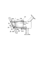
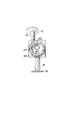
図面、そして特に図1を詳細に参照すると、本装置Aが取付けられる容器53が示されている。本発明は固定的な装入材料をもって容器に取付けるのも、あるいは固定的または可動の装入材料をもって導管に取付けるのも可能であることが察知されるべきである。図1のこの容器は本発明の一部ではないので、それは点線で示されている。以下で論述されるように、この装置Aは容器または導管の頂部、側面または底部に装着することが出来る。
Referring in detail to the drawings, and particularly to FIG. 1, there is shown a
容器53はその側面上に押えリング1を備えている。従来の押えリング1は、たとえば25mmの内径を有している。本装置Aの本体部10は通常、標準の押えリングの径に等しいか、僅かに小さい外径を有するように設計されている。ここでは25mmの寸法が示されているが、それは単に本装置Aの本体10の外径が、如何なる現存の押えリングの内径よりも僅かに小さいことを要するに過ぎない旨が認識されるべきである。従って、如何なる寸法の本装置Aも、如何なる寸法を有する管接続口を備えた現存の容器または導管に対し容易に装置修正する(retrofit)ことが出来る。勿論、本装置はまた新しく製作された容器または導管と組立てることも出来る。
The
容器または導管53に対して試料を装入するか、あるいは容器または導管53から試料を取出すために必要な装置は本装置の本体10を介して準備される。従って、本発明を利用する場合現存する装置を変更する必要はない。このアレンジメントが標準設計の容器または導管に対する容易な装置修正を提供する。
The necessary equipment for loading the sample into or removing the sample from the container or
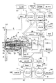
さて、図2に転じて、本装置Aを更に詳細に説明する。主試料サブアセンブリー2が示されている。このサブアセンブリーは金属(プラスチックまたはその他の材料)の単一片から機械加工出来るので、単一、ワン・ピースの統一構造体である。それにより数個所の付加的接合部の必要性が本装置によって排除される。それぞれのこの種接続部は汚染および機能不全に関する潜在地点を示すものである。しかしながら、本発明のユニークなシーリング・アレンジメントの故で、金属または他の材料から成る単一片から機械加工された主試料サブアセンブリーを用いることが必須であるという訳ではない。たとえば、サブアセンブリーを、本質的にワン・ピースとして機能する単一ユニット内に恒久的に固着(溶接、接着等)させることも可能である。
Now, turning to FIG. 2, the device A will be described in more detail. The
主試料サブアセンブリー2は内部腔3を備えた本体10を含んで成る。この腔3は以下でより詳細に論述する試料腔11および中央孔13を包含している。
The
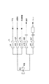
本発明の装置Aに連結されているのは制御手段4である。この手段はプログラマブル論理制御装置、制御装置等で操作されるコンピュータであればよい。制御手段の一部は検出手段4aを含んでいる。この制御手段4および検出手段4aのオペレーションは以下で一層詳細に説明するものとする。 Connected to the device A of the present invention is a control means 4. This means may be a computer operated by a programmable logic control device, a control device or the like. A part of the control means includes the detection means 4a. The operation of the control means 4 and the detection means 4a will be described in more detail below.
供給手段50は装置に対し水蒸気、空気および洗浄媒質の少なくとも1種類を供給するために設けられている。この供給手段50は無菌雰囲気を維持するのに役立つ。或る状況ではシステムを清掃するのに水蒸気のみで足りる。その他の用途においては純粋な乾燥空気または洗浄媒質を使用することが必要である。更に、これら物質の如何なる組合わせも使用可能である。洗浄媒質は洗剤、アルコール、アルカリ性すすぎ剤、酸性すすぎ剤またはその他の洗浄物質を含むことが可能である。本発明の清掃および/または滅菌のためには数多くの異なったアレンジメントを利用し得ることが明白であるに違いない。 The supply means 50 is provided for supplying at least one of steam, air and a cleaning medium to the apparatus. This supply means 50 helps maintain a sterile atmosphere. In some situations, only steam is needed to clean the system. Other applications require the use of pure dry air or a cleaning medium. In addition, any combination of these materials can be used. The cleaning medium can include detergents, alcohols, alkaline rinses, acidic rinses or other cleaning substances. It should be clear that many different arrangements can be utilized for cleaning and / or sterilization of the present invention.
本発明の供給手段50は蒸気供給弁ブロック5、純粋乾燥空気弁ブロック6および洗浄媒質弁ブロック7を包含する。蒸気供給弁ブロック5はダイヤフラム空気圧弁67に連結された水蒸気源66を含む。更に、電磁弁69を介してこの弁67に接続されているのは加圧空気源68である。本発明においてはあらゆる適切なタイプの自動または手動弁67および69が利用可能であること、あるいはこれら2種類の弁を単一ユニットに組合わせ得ることに注目すべきである。
The supply means 50 of the present invention includes a steam
純粋乾燥空気弁ブロック6は純粋乾燥空気源70を備えている。この純粋乾燥空気源70はダイヤフラム空気圧弁71に接続されている。更に、電磁弁72を介してこの弁71に連結されているのは加圧空気源73である。弁67および69と同様に、弁71、72に関して如何なるタイプの弁も使用可能である。更に、単一ユニットをこれら2個の弁71、72と置換することも可能である。
The pure dry
洗浄媒質弁ブロック7は洗浄媒質供給源74を含んでいる。上に述べたように、この洗浄媒質は洗剤洗浄物質、アルカリ性洗浄物質、酸性洗浄物質、アルコール洗浄物質または如何なる適切な清掃用アレンジメントであってもよい。洗浄媒質供給源74はダイヤフラム空気圧弁75に接続されている。再び、弁67、69、71および72と同様に、これら弁75および76に関してあらゆる適切な弁または単一ユニットを利用することが出来る。
The cleaning
電磁弁69、72および76は制御手段4に連結されるものとして示されている。ダイヤフラム空気圧弁67、71および75もまた制御手段4に接続されていることが言及されるべきである。制御手段4は単に、加圧空気、水蒸気、純粋乾燥空気および/または洗浄媒質の入口流路12への供給を制御することが必要であるに過ぎない。これら媒質のそれぞれは各弁67、71および75を経由して入口流路12に連絡している。更に、3個の弁ブロック5、6および7が示されているが、必要に応じてこれらのいずれかを省き、あるいは付加的な弁ブロックを使用してもよい。更に、弁69、72および76を組合わせて単一の弁としてもよい。
入口流路12は主試料サブアセンブリー2から供給手段50へ連続するものとして示されている。上で言及したように、この主試料サブアセンブリーは単一のブロックから機械加工することが出来る。適当な細管、配管またはその他のコネクタは、主試料サブアセンブリー2内に穿設された入口流路12を供給手段50に連結するために、使用することが出来る。三−クランプ接続部15はこの細管または配管を主試料サブアセンブリー内の入口流路に連結する。
ドレン流路14もまた本発明中で提供される。このドレン流路は主試料サブアセンブリー2内に穿設することが出来るし、あるいは試料51を収集するための下流手段およびドレン52を収集するための手段に配管連結することも出来る。これらの手段51および52はより詳細に以下で論述する。15で示した入口流路についての接続部と同様に、ドレン流路14は接続部16を備えている。接続部15および16による三−クランプを用いるのではなくて、何らかの適切な接続アレンジメントを利用してもよい。
A
入口流路12およびドレン流路14の両者は本体10の内部試料腔11に連結される。この本体10は試料腔11を含むのみならず、中央穴13を包含し、これらは共に上で言及した内部腔3を形成する。
Both the
中央穴13を経由して延在するのは弁作動ロッド22である。この弁作動ロッド22はその一端においてピン38に接続されている。このピン38は以下でより詳細に論述される手動オーバーライド・レバーとして機能する。ピン38は、オペレータがコネクタ・ピン38を把握し得るように領域42において露出される。ピン38は弁作動ロッド22を電磁アクチュエータ40のアクチュエータ・ピストン39に接続する。電磁アクチュエータ40はハウジング41内に配置される。
Extending through the
この電磁アクチュエータ40は制御手段4によって制御される。この制御手段4は、中央穴13内の弁作動ロッド22を往復運動させるために電磁アクチュエータ40を発動させることによって弁作動ロッド22を運動させることが出来る。もし、何らかの理由で、制御手段が働かなくなれば、オペレータは露出領域42を介してコネクタ・ピン38を簡単に握り、そして手動で弁作動ロッド22を往復運動させることが出来る。
The
電磁アクチュエータ40は別として、弁を開/閉するためのより安価なデザインを採用することも可能である。たとえば、電気または空気圧ソレノイド機構を利用することが出来る。更に、コネクタ・ピン38によりロッド22を把握する以外に、たとえばハウジング41を経由して延びるロッド63の下方端部を把握することも可能である。安全対策として、単にアクチュエータまたはロッドの或る部分が、手動操作可能であるようにオペレータに利用し易いことのみが求められる。
Apart from the
弁作動ロッドは後部弁作動ナット/ベアリング28および前部弁作動ナット/ベアリング26を経由して延在する。これらナット28、26の両者は中央穴13内に配置されている。ナット28および26が示されているが、本体10内に弁作動ロッド22を装着するためには如何なる適切なアレンジメントをも利用し得ることが察知されるべきである。しかし、この種のナット28、26を使用することによって、試料アセンブリー2の組立および分解を容易に行うことが出来る。
The valve actuation rod extends via a rear valve actuation nut /
後部弁作動ナット28の弁座43と弁作動ロッドの窪み23との間に延びているのはバネ27である。このバネ27は作動ロッド22をアクチュエータ41から離すように押圧する。これが、以下でより詳細に論述するように、蛇腹30の丸いシーリング尖端32をしてオリフィス33を閉塞せしめるのである。この方向に尖端32を押圧することによって、パワーの不足と同時に本装置は自動的にオリフィス33を閉じることになる。このようにして、本装置のフェールセーフ作動が保証される。
Extending between the
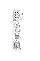
図3に目を転ずると、後部弁作動ナット28、前部弁作動ナット26、ワッシャー25、ブッシング24および蛇腹30が示されている。ダイヤフラム弁49は蛇腹30と共に弁作動ロッド・キャップ21、ロッド22、ブッシング24およびワッシャー25を包含している。図3および図4においては、後部弁作動ナット28が示されている。バネ27のための弁座43がこの図3中に示されている。更に、後部弁作動ナット28を経由する中央穴78が示されている。弁作動ロッド22はこの穴78を介して延在することになる。ナット28を締付けるための横断溝79もまた、これらの図中に示されている。
Turning to FIG. 3, the rear
図3および図5中には前部弁作動ナット26が示されている。後部弁作動ナット28と同様に、この前部弁作動ナット26は中央穴80および横断溝81を備えている。
3 and 5 show the front
ワッシャー25およびブッシング24は図3、図6および図7中に示されている。ワッシャー25が中央穴82を有しているのに対し、ブッシング24は中央穴83を備えている。ブッシング24はネック84およびベース85に分割されている。最後に、図3はダイヤフラム弁49の蛇腹30を示している。蛇腹の皺30は、物質をその中に閉込めないように充分に離間されている。
蛇腹30のベース29はブッシング24のネック84に対して圧縮される。このネック84は、中央穴13に近接する本体10のリップ64の内方環状側面に抗してベース29を押すことになる。この力は、ダイヤフラムのベースを動かないように保持し、かつ試料、水蒸気、空気および/または洗浄媒質が中央穴に進入するのを阻止するシールの形成を助ける。ブッシング24に対する圧力は中央穴13上の前部プッシュロッド・ナット26を締付けることによって生成される。ブッシング・ベース84およびナット26間のワッシャー25は、ナットが締付けられたときに生成されるトルクからブッシング24(および蛇腹30のベース29)を隔離する。
The
蛇腹30の他端において、球根形の丸いシーリング尖端32がサンプリング・オリフィス33における空所(停滞領域)を回避することになる。勿論、この丸いシーリング尖端32は数多くの方法で形成することが出来る。単に、オリフィスに対し適切なシールを形成することのみを要するものである。
At the other end of the
図2に戻ると、図3に示される構成要素の整列を理解することが出来る。弁作動ロッド22は後部弁作動ナット28、前部弁作動ナット26、ワッシャー25、ブッシング24を経由し、そして蛇腹30内に延在している。ワッシャー25はブッシング24のベース85および前部弁作動ナット26の一端86と係合状態にある。
Returning to FIG. 2, the alignment of the components shown in FIG. 3 can be understood. The
ブッシング24のネック84は蛇腹30についての緊密な支持のために設けられている。図2および図3中に見られる蛇腹は複数個の皺30aをもって示されている。しかし、オリフィス33から離れた蛇腹30の端部はフラットであるものとして示されている。これはブッシング24のネック84に起因している。
The
蛇腹30の使用は数種類の利点がある。先ず、運動する機械的パーツ(たとえば、弁作動ロッド22等)の全ては試料腔11内の試料から取外される。蛇腹30はバイオ適合性を有するプラスチックで、熱的または化学的耐性材料から調製される。この蛇腹は可撓性であり、そして広い動きの範囲を有している。この動きの大きな範囲が装置を、装置修正デザインにおける容器または導管の平面取付け(または図19に示すような貫通)を成就させる。更に、このデザインは丸いシーリング尖端32を大きな距離に亘ってサンプリング・オリフィス33から抜き出させる。この様相は装置をして、この特別な形状において6mmまでの寸法の粒子を伴う試料に関して最小の試料寸法傾向を提供させるものである。
The use of the
図8、図9および図10中に見られるように、弁作動ロッド22および弁作動ロッド・キャップ21が示されている。この弁ロッド22の端部はネジを切ったスクリュー87を備えていて、キャップ21内のネジ山88と噛合う。従って、キャップ21を弁作動ロッド21上に嵌め込むことが出来る。勿論、その他の連結アレンジメントを行うことも可能である。先に言及したバネ27はロッド22の窪み23と係合することになる。弁作動ロッド22の下端が図9中に示されている。弁作動ロッド22のネジを切った端部63はアクチュエータ40のアクチュエータ・ピストン39と係合する。勿論、ネジ切り連結以外の連結も可能である。
As seen in FIGS. 8, 9 and 10, the
弁作動ロッドの底面図および弁作動ロッド・キャップ21の頂面図がそれぞれ図9および図10中に示されている。この弁作動キャップ21および弁作動ロッド22の一部は蛇腹30内に挿入される。このキャップ21は、丸いシーリング尖端32が確実にオリフィス33をシールし、そしてオリフィス33を通り抜けて変形したり、突出したりしないことを保証する。更に、このキャップ21は、作動ロッド22が引込められたとき尖端32がオリフィス33の周囲の領域を突刺すことを妨げる。図8が示すようにキャップ21は、それが蛇腹30内にあるとき、作動してキャップ44内のオリフィス33から離れてシーリング尖端32をも引張るような態様で拡大されている。
A bottom view of the valve actuation rod and a top view of the valve
オリフィス33は図2および図12中に見られるように、本体10に関してキャップ44内に設けられている。本体10の端部はキャップ44を本体10に固着するための止めネジ37を備えている。それは、3個の止めネジ37が本体10の端部を経由し、かつキャップ44内に挿入されてキャップを適所に保持することが意図されるものである。図12中に見られるように、各止めネジ上のネジ山は、キャップ44を完全に貫通する前に終結せしめるか、あるいはキャップ44内に部分的に延在し得るものとする。止めネジ37の端部は平か、僅かに曲げてキャップ44の損傷を阻止すればよい。3個の止めネジ37はキャップ44の周囲を取り囲んで不等に離間している。この方法において、止めネジ37が挿入可能である前にキャップ44は適切に定位せねばならない。この主要効果は、キャップ44が本体10に装着される際、中央に位置していないオリフィス33が蛇腹30の丸いシーリング尖端32と適当に整列されるようにキャップ44の適切な配置を保証する。
The
勿論、その他のシーリング・アレンジメント、たとえばベイアニットまたはボルトおよびピン接続を行うことも出来る。更に、キャップ44を本体10内にねじ込むことが出来る。しかしながら、このデザインは、本体10上へのキャップ44の不完全なネジ留めが蛇腹30の丸いシーリング尖端32とオリフィス33の不適切な整列をもたらすという欠点を有している。更に、ネジを本体10に対し装架する間のキャップ44の回転運動は、このキャップ44および蛇腹30の尖端32間の摩擦を生ずる可能性があり、それがこの尖端を損傷するかも知れない。従って、止めネジまたはボルトの使用は、キャップが本体10上に直接ネジ留めされるデザインよりも好ましい。他の代替手段として、キャップ44および本体10を金属、プラスチックまたはその他の材料から成る単一片から機械加工することが出来る。
Of course, other sealing arrangements can be made, such as bayanite or bolt and pin connections. Further, the
キャップ44のオリフィス33はその前方端部に形成される。オリフィス33は、丸いシーリング尖端32がキャップ44と整列するように、その中心から片寄っている。キャップ44の環状側面90は容器または導管53の内部と接触している。僅かに凹ませて示されているが、尖端32とのキャップ44のシーリング地点は容器または導管53の壁56の内面と略同一平面にすることが可能である。それは単に、キャップ44が尖端32のシーリング圧力に耐えるに足る構造的強度を有することが必要とされるに過ぎない。容器または導管53の内壁56に対するキャップ44の、このシーリング地点がより接近すれば、停滞領域の進展に関して可能性はより低くなる。図2、図11および図12中に見られるように、Oリング34を受けるためにOリング溝35がキャップ44内に設けられている。同様な溝34aは、Oリング34を受けるために容器または導管53の壁内に設けられている。使用される容器または導管53によって、この溝34aを省いてもよい。溝35内のOリング34は弁または導管53の平らな表面に対して、あるいはその中に設けられた溝34aに対してシールを形成することが出来る。
The
キャップ44の内方側面にはOリング17を受けるための他の溝36が存在する。図2中に示されるように、本体10はこのOリング17を受けるための同様なOリング溝18を備えている。勿論、この溝18は省略してもよい。この種の溝18を伴い、あるいは伴わずに適切なシールを形成することが出来る。2個のOリング17および34を設けたので、適切なシールを試料腔11および容器または導管53の内部56間に維持することが出来る。換言すれば、試料はオリフィス33を経由してのみ流れることになる。Oリング17はあらゆるプロセス物質が、ネジを切った接合部37であって、キャップが本体10に連結する場所へ進入するのを阻止する。
There is another
これらOリング34および17の利用は、外部に対する漏洩防御の保証をもたらし、そして本体10に対するキャップ44の連結部および押えリング1内の本体10の連結部周囲の臨界領域において強化される過剰な圧力または真空の発生に起因する「ブリージング」に関する可能性を最小とする。
The use of these O-
付加的な溝およびOリングは必要により設けてもよい。上で言及したように、シール間で漏洩、汚染または受動的「ブリージング」が回避されるように充分なシールが提供されるべきである。このシーリング・アレンジメントの故で、キャップ44と本体10との間であって、圧力の変化による試料腔11内への物質の漏れ戻りに起因して引続く試料が汚染されるかも知れない場所で試料、水蒸気、洗浄媒質等は漏洩しなくなる。
Additional grooves and O-rings may be provided as needed. As mentioned above, sufficient seals should be provided so that leakage, contamination or passive "breathing" between seals is avoided. Because of this sealing arrangement, between the
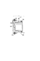
更に、図2および図11中に示されているのは、本体10を押えリング1に連結するための手段57である。図11に示されているこのネジタイプの手段は、本発明の装置Aを容器または導管53に連結するための単なる一例に過ぎない。本体10の前部側面91は連結手段57の後部側面と係合する。この連結手段57は、適所にネジ留めされたとき押えリング1に抗して本体10を保持することになる。
Also shown in FIGS. 2 and 11 are means 57 for connecting the
連結手段57は、本体10内の環状凹部104内に収容された保持リング92を含んでいる。リング92は、リング92の前方運動を阻止するこの凹部104の前部側面と係合する。このリング92は、本体10の前方側面91に近接することになる。本体10は側面91を越えて延在し、かつキャップ44に延びていることが注目されるべきである。あるいは上で言及されたように、キャップ44を、本体10が実際に延びて容器または導管53内の試料と接触するように、本体10と一体に製作してもよい。しかしながら、簡略化のために、この側面91は単に前部側面と称されて来た。それは容器または導管53に面しているからである。
The coupling means 57 includes a retaining
保持リング92はカップラー105と係合する。このカップラー105は押えリング1の外側のネジ107と係合するネジ山106を備えた前端部を有している。カップラー105を回して嵌め込むと、本体10を押えリング上に装着することが出来る。上で言及したように、本体10を押えリング1に装着するためには数多くの他の連結アレンジメントを提供し得ることが察知されるべきである。
Retaining
図11中に示されたアレンジメントにおいて、容器または導管の壁56は傾斜したものとして示されている。容器について、数多くの異なった相対的配置もまた可能であることが察知されるべきである。本体10および/またはキャップ44の前方端部を、壁56の内面と噛合わせるために適当に傾斜させてもよい。
In the arrangement shown in FIG. 11, the container or
図2に戻ると、プローブ20がドレン流路14のプローブ・オリフィス19内に示されている。このプローブ20およびオリフィス19は試料腔11内で選択的に、あるいはドレン流路14および試料腔11の両者中で選択的に位置決めすることが可能である。プローブ20は温度および/または圧力プローブであればよい。このプローブ20は制御手段4の検出手段4aに対し作動的に連結されている。
Returning to FIG. 2, the
検出手段4aおよびプローブ20はシステムのオペレーションの各種局面について独立した検証を提供することが出来る。プロフィルに関してシステムが正確に作動している場合のサンプリングシステム温度または圧力のプロフィルを比較することによって、そのシステムの各種構成要素が働かない場合、確定はシステムの故障(異常作動)について検出手段4aよって行うことが出来る。更に、確定は故障の重大度に関して、またこれ以上のサンプリング・サイクルを中断するか、ならびに警報を発するか否かについてこのシステムによって行うことが出来る。温度または圧力プロフィルはプローブ20により捕捉され、そして検出手段4aに供給される。従って、たとえば、もし蛇腹30が裂開したとすれば、プローブ20はこの状態を確定することが出来る。更に、もし入口流路12内に阻害が生じたとすれば、この状態を検出することが出来る。検出手段4aは制御手段4と共に適切なアクションを開始することが出来る。このプローブ20はまた、滅菌サイクルの間適切な蒸気温度に到達しているかどうかを検出することも出来る。
The detection means 4a and the
ドレン流路14から下流は試料収集手段51およびドレン収集手段52である。試料収集手段51は試料ドレン弁ブロック8を備えている。この弁ブロック8は試料収集器94に連結されたダイヤフラム空気圧弁93を有している。この試料収集器はたとえば、試料ガラス瓶サブアセンブリーであればよい。更に、ダイヤフラム空気圧弁93に連結されているのは加圧空気源96を備えた電磁弁95である。
Downstream from the
ドレン弁ブロック9は廃棄手段98に連結されたダイヤフラム空気圧弁97を含む。更に、ダイヤフラム空気圧弁97に連結されているのは電磁弁99および加圧空気源100である。弁67、71および75と同様に、ダイヤフラム空気圧弁93および97はあらゆる知られた弁と置換可能である。同様に、弁95および99はまたその他の弁によって置換可能であるし、あるいは弁93および95ならびに弁97および99を組合わせて単一のユニットとすることも出来る。図2に示したように、電磁弁95および99は制御手段4に対し作動的に接続される。
The
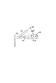
さて、図13および図14に転じて、入口流路12およびドレン流路14に関してその相対的配置を説明する。弁作動ロッド22のための中央穴13の片側に入口流路12が存在する。この入口流路は試料腔11に向って下傾している。試料腔11の内表面は通常平らである。この内表面と同一表面を為して備えられているのはドレン流路14用の開口部48である。このドレン流路14は試料腔11から離れて下方に傾斜している。図14において、キャップ44は省略されている。
Turning now to FIGS. 13 and 14, the relative arrangement of the
図13において理解し得るように、ドレン流路14の傾斜角は入口流路12の傾斜角よりも小さい。勿論、ドレン流路14と入口流路12との、この角度の関係は変更可能である。たとえば、入口流路12と本体10の軸との為す角度より大きなドレン流路14と本体の軸との角度を提供することも可能である。
As can be seen in FIG. 13, the inclination angle of the
ドレン流路14上方の入口流路12の配置ならびにドレン流路14と試料腔11の底部壁との同一平面装備に起因して、蓄積阻止手段45が形成される。この手段は試料腔11からドレン流路14への試料の自由流れを可能にする。試料の溜りは回避されることになる。それ故、有り得る引続く試料の汚染は回避される。
Due to the arrangement of the
更に、ドレン流路14は内径6mmを有している。これは一般に容器53から抜き出される最大試料粒子よりも大きい。この方法で、ドレン流路14の詰りは回避される。
Further, the
図14において理解されるように、弁作動ロッド22、入口流路12および出口流路14を有する中央穴13の片寄り装備の故で、これらの部分のそれぞれを本体10の外径に関する25mm拘束の範囲内で締付けることが可能である。この方法において、本体10は現存の装置内で装置修正出来る。上で言及したように、押えリング1の内径は多くの装置において典型的に25mmである。この寸法は変更し得るが、本発明を、この装置の装置修正の必要性なしに現存装置内に挿入し得ることが理解されるべきである。勿論、より大きなあるいは小さい押えリング口が存在すれば、本発明はこれらの押えリングをより大きくあるいは小さくしてそれらを対応的により大きなあるいは小さい構成要素に適合させることが出来る。
As can be seen in FIG. 14, due to the offset arrangement of the
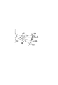
図15−図17において、本発明装置の装着が概略的に示されている。もし、本装置を図15に示すように水平に定位する押えリング1に装着する場合は、本体10の長軸65は通常水平である。入口流路12についての長軸59は軸65から角度約18.5゜だけ片寄ることになる。ドレン流路14の長軸58は本体の長軸65から約3゜だけ片寄ることになる。従って、入口流路12の傾斜はドレン流路14の傾斜より大きい。このことが試料、水蒸気、空気、洗浄媒質および/または凝縮液の適切な排流を保証する。
15 to 17 schematically show the mounting of the device of the present invention. If the apparatus is mounted on the holding
図16に示すように、もし、押えリング1がたとえば、下方に水平面hから15゜だけ傾斜していれば、本体10の長軸65は同様に15゜だけ片寄ることになる。この種の15゜の下方傾斜は容器または導管53における何れかの管接続口の標準設計である。この下方傾斜によって、ドレン14の長軸58は水平面hから約18゜片寄ることになる。入力流路12の長軸59は下方勾配をもって連続することになる。この軸59は水平面hから約3.5゜だけ片寄ることになる。従って、下方に定位する押えリング1により適切な流れが連続し、本発明によって維持可能となる。試料、ならびに水蒸気、空気、洗浄媒質および/または凝縮液の溜りをこのアレンジメントにおいて回避することが出来る。
As shown in FIG. 16, if the
図17の上方に傾斜した押えリング1において、ドレンの長軸58は入口流路12の長軸59よりも小さな傾斜を有することになる。それにも拘らず、このアレンジメントはシステムを通じて物質を推進し続ける。
In the holding
本発明のプロセス制御は制御手段4の支配下で遂行される。上に言及したように、この制御手段4はプログラマブル論理制御装置、制御装置またはその他のあらゆる適当な制御手段によって操作されるコンピュータであればよい。制御手段4は本発明の各種の弁を適切な順番に並ばせる。集合的に、このシステムは各弁の開放/閉塞ならびにサンプリング装置の順番を整え、かつ時間を決めるが、オペレータに各弁が解放された侭となる時間の長さをプログラムさせるものである。このことが、それによってプロセス制御システムが様々に異なったプロセス用途に適合し、かつ組入れ可能である手段を提供することになる。 The process control of the present invention is performed under the control of the control means 4. As mentioned above, the control means 4 may be a programmable logic controller, a controller or a computer operated by any other suitable control means. The control means 4 arranges the various valves of the present invention in an appropriate order. Collectively, the system arranges the opening / closing of each valve as well as the sequence of the sampling device and determines the time, but allows the operator to program the length of time each valve remains open. This provides a means by which the process control system can be adapted and integrated into a variety of different process applications.
異なった寸法の弁、異なった構成材料、異なったプロセス流れ温度および流速、異なった洗浄剤または化学薬品(水蒸気、空気、洗浄媒質等)ならびにその他のプロセス物質は操作(サンプリング、清掃、滅菌、再サンプリング等)の多様な様相の適切なタイミングに影響を及ぼす可能性がある。さて、本発明システムの基本的な構成要素についての単一サイクル・シーケンスを論述するものとする。 Different sized valves, different materials of construction, different process flow temperatures and flow rates, different cleaning agents or chemicals (steam, air, cleaning media, etc.) and other process materials may be operated (sampling, cleaning, sterilizing, reprocessing). (E.g., sampling). Now, a single cycle sequence for the basic components of the system of the present invention will be discussed.
5個の周辺プロセス流れ制御弁5、6、7、8および9と協力して制御手段4は主試料サブアセンブリー2が機能するのを制御する。この制御シーケンシングは図20および図21中にレイアウトされている。このシーケンスは各サンプリングの前に、入口流路12、主試料サブアセンブリー2およびドレン流路14を清掃かつ滅菌するために設計されている。このシステムはまた、サンプリング物質の最後のものを廃棄手段98内にパージする。丸いシーリング尖端32がオリフィス33を閉じた後、システムはまた各サンプリングの間で清掃および再滅菌を行う。
In cooperation with the five peripheral process
たとえば、純粋蒸気供給ブロック5は、水蒸気の流れを制御してこのシステムを滅菌する。同様に、純粋空気供給ブロック6は二つの目的のためにシステムを通じて純粋空気の流れを制御する。先ずこの空気は、サンプリングの後で残ったかも知れないあらゆるサンプリング物質を取除くように、入口流路12、試料腔11、ドレン流路14を経由して吹込まれ、そして廃棄手段98に至る。この空気はまた、滅菌段階の後残留するあらゆる水蒸気凝縮液を完全に除去するように、ドレン流路14に吹込まれる。この純粋空気は次の試料が取出される前にサンプリングシステムを冷却かつ乾燥させることになる。もし、水蒸気が不十分であれば、洗浄媒質を洗浄媒質弁ブロック7により供給して、システムを清掃することが出来る。同様に、水蒸気と洗浄媒質の組合わせを使用することが出来る。純粋乾燥空気70はまた、システムから洗浄媒質をフラッシするのを補助するために、そして洗浄媒質の使用後、システムを乾燥させるために使用することが出来る。
For example, the pure
清掃および滅菌の間、ドレン・ラインブロック9は開放状態で凝縮液、洗浄媒質等を排出する。他方、試料瓶ブロック8は開放状態で試料物質を試料収集器94内に流入させる。
During cleaning and sterilization, the
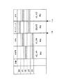
図20において、弁49、71、67、93および97はそれぞれSO、V1、V2、V3およびV4で示される。この図中に示されるように、サンプリング操作の一つのタイプの間に先ず、待ち時間に遭遇することになる。V1およびV4で示された弁が開放される。換言すれば、ダイヤフラム空気圧弁67および97が開放される。水蒸気は供給源66から入口流路12、試料腔11を経由して急行し、そしてドレン流路14を出て、廃棄手段98に至るのに対し、弁97は依然として開放されている。適当な時間の後、弁67は閉じられ、そして弁71は開放される。次いで、純粋乾燥空気はシステムを経由して急行し、廃棄手段98に至ることが可能である。この純粋乾燥空気はこのシステムを経由してあらゆる残留粒状物質を強制するのみならず、また装置の内面を冷却および乾燥するのを補助する。
In FIG. 20,
図21のタイムチャートにおいて、次に1秒の遅延を示す。この遅延は省略することが出来るし、あるいはより短いまたはより長い期間とし得ることが認識されるべきである。サンプリングは次に行われる。このアレンジメントにおいて、弁SOおよびV3は開放状態として示されている。換言すれば、弁49が開放されて、試料がその管接続口54を経由して容器または導管53を出て行くことを許容する。物質はオリフィス33を経由して試料腔11内に移動し、そしてドレン14を下り、試料収集器94に至る。図21のアレンジメント中には示されていないが、もしそう望むなら試料の最初の部分が実際に廃棄手段に進むように、弁93を最初に閉塞し、そして弁97を開放し得ることが注目されるべきである。いずれの場合も、弁93が開放される前に弁97を閉じるべきである。
In the time chart of FIG. 21, a one second delay is shown next. It should be appreciated that this delay can be omitted or can be of shorter or longer duration. Sampling is performed next. In this arrangement, valves SO and V3 are shown as open. In other words,
試料が入口流路12に入るのを阻止するために試料腔11の内部には弁は全く設けられていない。内圧が、試料の入口流路12への移動を阻止するに足るように、弁67、71および75は閉じられる。更に、重力もまた試料が入口流路12へ移動するのを阻止する。従って、装置Aは簡略化され、そして一つには余分な弁の省略に起因する変形を伴うことなく、現存の容器または導管53において使用することが出来る。換言すれば、比較的小寸法の本体10を、既存の容器または導管口と適合性があるように、維持することが可能である。更に、この種の付加的弁を省くことによって汚染の潜在的部位が回避される。
No valve is provided inside the
充分な試料が収集器94で選択された後、別の1秒の遅延が図21に示されている。再び、遅延無しとするか、あるいはより長いかまたは短い時間を提供することも可能である。次いで、図21においてSOで示される弁49が閉じられ、そして弁71が開かれる。次に、純粋乾燥空気がシステムを経由して急行し、試料を腔11内、そしてドレン流路14から試料収集器94へと適切に強制する。よって、本発明装置の一回の操作が説明されたことになる。所望ならば、洗剤媒質弁ブロック7もまた操作可能であることが理解されるべきである。しかし、図21のアレンジメントにおいて、供給源74からの洗浄媒質は使用されない。
After enough samples have been selected at the
先に言及したように、図19中のアレンジメントは容器または導管53内に挿入される装置の本体10を示している。停滞層60が容器内に存在しているかも知れない場合、図19中に示された装着アレンジメントを使用することが出来る。このデザインはオリフィス33をこれらの停滞層60を越えて配置するものである。図19のこのデザインにおいて用いられる装置Aは、2個のOリング溝35および35’がキャップ44上に設けられていること、およびこのキャップ44の長さが図19におけるより大きいことを除けば、図2のアレンジメントに類似している。単一Oリング34は必要により2個の溝35または35’間に移動させることが出来る。勿論、2個の別々のOリングを設けることも可能で、各溝について1個とする。しかし、装置Aが図19中に示されるように配置される場合は、前部溝35から1個のOリングを省くことが好ましい。この方法において、物質がキャップ44の前部、外方端において捕捉されるされることになる場合が恐らく少なくなる。
As mentioned earlier, the arrangement in FIG. 19 shows the
本体10が図19のアレンジメント内に装着された後、この本体10は移動不能となることが察知されるべきである。もっと適切に言えば、その作動の間に示された所定距離について容器または導管53内でそれは延びている。勿論、この装置が最早不要となれば、連結手段57は簡単に取外すことが出来、そしてこの装置Aは容器または導管53から除去される。前部Oリング溝35の故で、この本体10は容器または導管53の壁61と略同一平面を為すように装着出来る。Oリング34を備えたOリング溝35’は、装置Aが図19に示されるように延在すると、本体10および容器または導管53間でシールを形成することになる。あるいは、キャップ44の面が一般的に容器または導管53の内部61と平面を為せば、溝35内のOリングは装置Aおよび容器または導管53間でシールを形成することになる。Oリング34は後部溝35’から前部溝に移動可能であるか、あるいは後部溝35’がOリング34を保持し、または保持しない一方、新しいOリングを溝35内に挿入することが出来る。
It should be noted that after the
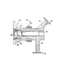
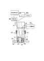
現時点まで、本発明はサンプリング装置として論述されて来た。図18中に示されるように、本発明はまた供給/播種手段として利用可能である。図18において、装置Aは容器53の頂部に装架されている。供給/播種装置として用いる場合、本発明はまた、容器53の側面に装架することも出来る。
To date, the present invention has been described as a sampling device. As shown in FIG. 18, the present invention can also be used as a feeding / seeding means. In FIG. 18, the device A is mounted on the top of the
図18に示された供給/播種アレンジメントは先に論述したサンプリング・アレンジメントに類似している。しかしながら、このアレンジメントにおいて、試料または清掃物質の溜りを阻止するためにドレン流路14は試料腔11内に充分延びている。ドレン流路14のための開口部48はオリフィス33を有するキャップ44の壁に通常隣接している。
The feed / seeding arrangement shown in FIG. 18 is similar to the sampling arrangement discussed above. However, in this arrangement, the
図18中に示されるように、手段101が試料を供給するために設けられている。この手段101は試料を入口流路12、試料腔11、オリフィス33を経由し、そして容器または導管53内に供給する。試料がオリフィスまたは導管に装入された後、シーリング尖端32が移動されてオリフィス33を閉じる。次いで、供給手段50は入口流路12、試料腔11を経由し、そしてドレン流路14を離れて、ドレン収集手段52へ水蒸気、乾燥空気および/または洗浄媒質を供給することが出来る。
As shown in FIG. 18, means 101 is provided for supplying a sample. This means 101 supplies the sample via the
図18中に概略的に示されているのは、供給手段50および試料供給手段101と共に利用されるスイッチング手段102である。この手段102は、手段101が入口流路12を経由して試料を供給するものとするか、あるいは供給手段50が入口流路12およびその他の下流構造体を清掃および/または滅菌するものとするかを選択する。
Shown schematically in FIG. 18 is a switching means 102 used with the supply means 50 and the sample supply means 101. The means 102 may be such that the
試料腔11の端部に配置されたドレン流路14の端部48を有することは別として、ドレン流路14の直径は、試料腔11内の圧力(流路12を経由する流入物から生成される)が、入口流路12を介して供給され、そしてドレン流路14を離れて行くあらゆる物質を強制するに足るように、充分小さい径を有するものとする。この方法において、試料腔11に供給される試料の寸法は入口流路12の寸法により制限される。供給手段50が操作されると、如何なる試料またはその他の汚染物質をもドレン流路14を経由して収集手段52へ強制するために、充分な空気、水蒸気および/または洗浄媒質を入口流路12を経由して供給することが可能である。別の状況では、図18中に示される供給/播種アレンジメントのデザインは先に論述した試料アセンブリーと同様である。
Apart from having the
本装置Aは数個の利点を有している。その立体形は本体10およびその容量を、それが現存の容器または導管中に装置修正し得るように比較的小さくすることを可能とするものである。たとえば、押えリング1の25mmの標準寸法を本発明に適合させることが可能である。
The device A has several advantages. The configuration allows the
本発明は独特にに設計されたバイオ適合性、再滅菌可能な可撓性ダイヤフラムを提供するものであり、これは試料抽出用オリフィスを容器または導管53と同一平面として装着させるか、あるいは容器または導管内に貫通せしめるものである。カスタマイズド・サブアセンブリー設計が可能であり、ここにおいて汚染しがちな、対向する摺動/回転面は試料によりシールされる。たとえば、蛇腹30は試料を弁49の作動部分から分離かつ隔離する。他の制御特色は、たとえば蒸気供給弁ブロック5、純粋乾燥空気弁ブロック6および洗浄媒質弁ブロック7が試料から取外されることである。汚染しやすいパーツはプロセスから除去されるので、本装置Aは一層効果的な総体的衛生設計となる。
The present invention provides a uniquely designed, biocompatible, re-sterilizable, flexible diaphragm which mounts the sample extraction orifice flush with the container or
本装置Aはフリー排液であり、それで溜りを回避する。試料または排液の溜りあるいは蓄積を更に回避するように、試料腔11およびドレン流路14間にポケットは存在しない。
The device A is free drainage, thereby avoiding pooling. There are no pockets between the
全ての二次的シールは固定されて、システム内の漏洩および/または外部環境に対する最も有効なバリヤーを提供する。プロセス側の当接面間の界面(ひび関連の持越し汚染が屡々発生する)は固定シールをもって(ダイヤフラム−タイプのシールである特別にデザインされた一次シールの例外を伴って)シールされる。本発明は動的Oリングシールの必要性を回避する。試料腔11における空隙率は最小となる。曲りくねった流れもまた、回避される。従って、サンプリング・プロセス中の試料物質の最小の損失ならびに測定試量についての最大の再現性および精度が本発明によりもたらされる。小容量を用いることによって、測定値中では小さな誤差のみとなる。
All secondary seals are fixed to provide the most effective barrier to leakage and / or the external environment within the system. The interface between the abutment surfaces on the process side (where crack-related carryover often occurs) is sealed with a fixed seal (with the exception of a specially designed primary seal that is a diaphragm-type seal). The present invention avoids the need for a dynamic O-ring seal. The porosity in the
論述した、この25mm外径デザイン内で、本デザインは外径6mmまでの粒子を容器または導管53から試料腔11を経由し、そしてドレン・ライン14を離れて、試料収集器94へと通過させる。それ故、試料構成体の物理的歪みは回避され、それによって採取された試料が寸法除外に起因して片寄らせられることはない。
As discussed, within this 25 mm outer diameter design, this design passes particles up to 6 mm in outer diameter from the container or
本発明の全ての固定的ネジ留め接続部および当接面は固定的Oリングシールの後方に配置される。これがトラブルを起しがちな界面をプロセス流れとの接触から取除く。 All fixed screw connections and abutment surfaces of the present invention are located behind the fixed O-ring seal. This removes troublesome interfaces from contact with the process stream.
本発明の制御手段4および検出手段4aは自動サンプリングあるいは播種を提供する。従ってオペレータ誤差が回避される。動力故障の場合ですら、補助的手動装置もまたサンプリングを許容するものである。 The control means 4 and the detection means 4a of the present invention provide for automatic sampling or sowing. Therefore, operator errors are avoided. Even in the event of a power failure, auxiliary manual devices also allow for sampling.
システムの圧力または温度分布を測定すること、ならびに独立の間接的検証が一層信頼性のある操作を可能とする。 Measuring the pressure or temperature distribution of the system, as well as independent indirect verification, allows for more reliable operation.
従って、本発明によればプロセス組成物の精確な副試料が得られる。このアレンジメントは現存システムまたは新しいシステムと共に使用することが出来る。本装置のメンテナンスは容易に行うことが出来る。 Thus, according to the present invention, an accurate sub-sample of the process composition is obtained. This arrangement can be used with existing or new systems. The maintenance of this device can be performed easily.
所望により、本発明の本体10は金属、プラスチックまたはその他の材料から成る単一片から機械加工出来るので、付加的な接続の必要性が排除される。このことはまた、試料の汚染に関する潜在的な地点を回避するものである。更に、シーリング尖端32の球根状デザインは空所を回避する。
If desired, the
制御手段4の故で、そのタイミング・シーケンスは容易に変更出来る。たとえば、オペレータはサンプリング・プロセスにおける各段階の長さを変更出来るし、また温度および/またはセンサー・プローブ19を使用して、システム内に何らかのエラーが発生しているかどうかを決定することが出来る。
Because of the control means 4, its timing sequence can be easily changed. For example, the operator can change the length of each step in the sampling process and use temperature and / or
発明は以上のように説明されているので、本発明を数多くの方法において変更し得ることは明白である。この種の変更は本発明の精神および範囲からの逸脱と考えられるべきではなく、また当業者には明らかであるような全ての、この種変形は以下の請求の範囲内に含まれるべきことが意図されている。 Having thus described the invention, it will be apparent that the invention can be varied in many ways. Such changes should not be deemed to depart from the spirit and scope of the invention, and all such modifications as would be apparent to those skilled in the art should be included within the scope of the following claims. Is intended.
Claims (3)
弁本体を有し、前記弁本体は、前記押えリングの内径の軸の傾斜の角度より大きいか等しい、前記容器または導管から離れる方向に傾斜した角度をもった内部ドレン流路を有する
ものである弁。 A valve mounted on an inclined holding ring in the wall of a container or conduit, wherein the axis of the inner diameter of the holding ring has an angle inclined away from the container or conduit.
A valve body, the valve body having an internal drain passage inclined at an angle away from the vessel or conduit, which is greater than or equal to the angle of inclination of the axis of the inner diameter of the holding ring. valve.
請求項1に記載の弁。 The valve body includes a sample cavity with an orifice located at a front portion, the valve body and the orifice each having a major axis extending through a center, and the major axis of the valve body is the major axis of the orifice. The valve of claim 1, wherein the valve is offset from the axis.
請求項1に記載の弁。 The valve body includes a sample cavity with an orifice located at the front, the hold down ring and the orifice each have a long axis extending through the center, and the long axis of the hold down ring is the length of the orifice. The valve of claim 1, wherein the valve is offset from the axis.
Applications Claiming Priority (1)
| Application Number | Priority Date | Filing Date | Title |
|---|---|---|---|
| US07/911,052 US5296197A (en) | 1992-07-09 | 1992-07-09 | Automated sample extractor or feeder/inoculator for bioreactors and similar equipment |
Related Parent Applications (1)
| Application Number | Title | Priority Date | Filing Date |
|---|---|---|---|
| JP50346294A Division JP3662923B2 (en) | 1992-07-09 | 1993-07-07 | Automated sample extraction or feeding / seeding device for bioreactors and similar devices |
Publications (1)
| Publication Number | Publication Date |
|---|---|
| JP2004190860A true JP2004190860A (en) | 2004-07-08 |
Family
ID=25429692
Family Applications (2)
| Application Number | Title | Priority Date | Filing Date |
|---|---|---|---|
| JP50346294A Expired - Fee Related JP3662923B2 (en) | 1992-07-09 | 1993-07-07 | Automated sample extraction or feeding / seeding device for bioreactors and similar devices |
| JP2003420343A Pending JP2004190860A (en) | 1992-07-09 | 2003-12-18 | valve |
Family Applications Before (1)
| Application Number | Title | Priority Date | Filing Date |
|---|---|---|---|
| JP50346294A Expired - Fee Related JP3662923B2 (en) | 1992-07-09 | 1993-07-07 | Automated sample extraction or feeding / seeding device for bioreactors and similar devices |
Country Status (5)
| Country | Link |
|---|---|
| US (3) | US5296197A (en) |
| EP (1) | EP0649521A4 (en) |
| JP (2) | JP3662923B2 (en) |
| CA (1) | CA2139740C (en) |
| WO (1) | WO1994001750A1 (en) |
Families Citing this family (80)
| Publication number | Priority date | Publication date | Assignee | Title |
|---|---|---|---|---|
| DE3431541A1 (en) * | 1984-08-28 | 1986-03-06 | Hoechst Ag, 6230 Frankfurt | CIS, ENDO-2-AZABICYCLOALKAN-3-CARBONIC ACID DERIVATIVES, METHOD FOR THE PRODUCTION THEREOF, THEIR USE AND INTERMEDIATE PRODUCTS IN THEIR PRODUCTION |
| US6821773B1 (en) * | 1992-07-09 | 2004-11-23 | Nl Technologies, Ltd. | Drainable ferrule valve design |
| US5296197A (en) * | 1992-07-09 | 1994-03-22 | Nl Technologies, Limited | Automated sample extractor or feeder/inoculator for bioreactors and similar equipment |
| US6133022A (en) * | 1992-07-09 | 2000-10-17 | Nl Technologies, Limited | Automated sample extractor or feeder/inoculator for bioreactors and similar equipment |
| US5660201A (en) * | 1993-12-21 | 1997-08-26 | Lockheed Martin Idaho Technologies Company | Multiple source/multiple target fluid transfer apparatus |
| GB9405038D0 (en) * | 1994-03-15 | 1994-04-27 | Counting Tech Ltd | Fluid valve assembly |
| US5441071A (en) * | 1994-05-04 | 1995-08-15 | Mclane Research Laboratories, Inc. | Automated water sample collecting system |
| DE4432599C2 (en) * | 1994-09-13 | 1996-10-31 | Thomae Gmbh Dr K | Sampling procedure for bioprocess analysis |
| US5452618A (en) * | 1994-09-23 | 1995-09-26 | The Boc Group, Inc. | Mechanism for oscillating a sample holder within a sample vessel |
| US5637792A (en) * | 1994-12-08 | 1997-06-10 | Sanshin Kogyo Kabushiki Kaisha | Exhaust gas sampler |
| US5746239A (en) * | 1995-09-19 | 1998-05-05 | Hunt-Wesson, Inc. | Dual trace valve system |
| US5962317A (en) * | 1995-10-18 | 1999-10-05 | The Johns Hopkins University School Of Medicine | Dosage modeling system |
| WO1997014962A1 (en) * | 1995-10-18 | 1997-04-24 | John Hopkins University | Dosage modeling system |
| US6287848B1 (en) | 1995-10-18 | 2001-09-11 | Johns Hopkins University | Dosage modeling system |
| US5914092A (en) * | 1995-10-31 | 1999-06-22 | Pfizer Inc. | Fermentation tank sample valve steam sterilization apparatus |
| JP3362823B2 (en) | 1995-11-02 | 2003-01-07 | 富士通株式会社 | Injection mold design equipment |
| US6408217B1 (en) | 1996-03-12 | 2002-06-18 | Fujitsu Limited | Computer aided design system and three-dimensional design method using the same and storing medium |
| AU723574B2 (en) * | 1996-05-17 | 2000-08-31 | Smith, Gregory Paul | Dry powder sampler |
| FR2752936B1 (en) * | 1996-09-02 | 1998-11-13 | Parron Pierre | SAMPLING TAP |
| US5823222A (en) * | 1996-10-31 | 1998-10-20 | Labatt Brewing Company Limited | Sanitary sampling device and method for using same |
| US6079285A (en) * | 1997-10-01 | 2000-06-27 | Baker; Jack T. | Robotic sampler for remote sampling of liquids in a process stream |
| US5948998A (en) * | 1998-02-09 | 1999-09-07 | Alberta Research Council | Sampling device for taking sterile samples |
| AU2666299A (en) | 1998-02-10 | 1999-08-23 | Nl Technologies, Ltd. | Housing for receptacle filling |
| US6068238A (en) * | 1998-03-30 | 2000-05-30 | Frank; Wolfgang J. | Valve assembly with automatic sampling system |
| CA2356385A1 (en) | 1998-12-24 | 2000-07-06 | Nl Technologies, Ltd. | Dip tube valve assembly |
| US7389792B2 (en) * | 1998-12-24 | 2008-06-24 | Nl Technologies, Ltd. | Dip tube valve assembly |
| JP3670503B2 (en) * | 1999-01-12 | 2005-07-13 | 株式会社日立製作所 | Dispensing device |
| DK174591B1 (en) * | 1999-03-31 | 2003-07-14 | Oestergaard Maskinfabrik As | Valve and method for closing a valve |
| EP1045238A3 (en) * | 1999-04-14 | 2002-09-11 | Nisco Engineering AG | Sampling valve and device for low loss extraction of liquid samples from a cavity |
| US6205869B1 (en) * | 1999-08-12 | 2001-03-27 | Sentry Equipment Corporation | Apparatus and method for sampling fluid from reactor vessel |
| US6546819B1 (en) | 1999-08-12 | 2003-04-15 | Sentry Equipment Corporation | Apparatus for sampling fluid from reactor vessel |
| US6491283B2 (en) | 2000-03-09 | 2002-12-10 | Nl Technologies, Ltd. | Sanitary drain valve design |
| SE0100283D0 (en) * | 2001-01-31 | 2001-01-31 | Astrazeneca Ab | Sampling apparatus |
| US20050236599A1 (en) * | 2001-03-09 | 2005-10-27 | Newberg Douglas A | Sanitary drain valve design |
| JP2005504232A (en) * | 2001-06-06 | 2005-02-10 | エヌエル テクノロジーズ リミテッド | Thermal insulation interface |
| US6845676B2 (en) * | 2001-12-14 | 2005-01-25 | Darrell Lee Bigalke | Continuous fluid sampler and method |
| US7314759B2 (en) * | 2001-12-14 | 2008-01-01 | Darrell Lee Bigalke | Continuous fluid sampler and method |
| EP1499383B1 (en) | 2002-04-26 | 2011-01-19 | Millipore Corporation | Disposable, sterile fluid transfer device |
| DE10241833A1 (en) * | 2002-09-09 | 2004-03-18 | Mettler-Toledo Gmbh | Retractable fitting with one sensor |
| US20040051067A1 (en) * | 2002-09-12 | 2004-03-18 | Fujita Mahoro M. | Pressurized valve actuator |
| US7553455B1 (en) * | 2003-04-02 | 2009-06-30 | Sandia Corporation | Micromanifold assembly |
| US20040260414A1 (en) * | 2003-06-20 | 2004-12-23 | Groton Biosystems, Llc | Method and apparatus for operating an automated biomolecular preparation system |
| US7169599B2 (en) * | 2003-06-20 | 2007-01-30 | Groton Biosystems, Llc | Fluid interface for bioprocessor systems |
| US7601545B2 (en) * | 2003-06-20 | 2009-10-13 | Groton Biosystems, Llc | Automated macromolecule sample preparation system |
| US7341652B2 (en) * | 2003-06-20 | 2008-03-11 | Groton Biosytems, Llc | Stationary capillary electrophoresis system |
| US7081361B2 (en) | 2003-08-07 | 2006-07-25 | Nch Corporation | Biomass generator |
| US7293477B2 (en) * | 2003-12-23 | 2007-11-13 | Millipore Corporation | Disposable, pre-sterilized fluid receptacle sampling device |
| JP4427689B2 (en) * | 2004-07-08 | 2010-03-10 | オークマ株式会社 | Machine Tools |
| US7578205B2 (en) * | 2005-06-01 | 2009-08-25 | Millipore Corporation | Sterile sampling device |
| EP1764603A1 (en) * | 2005-09-20 | 2007-03-21 | AC Analytical Controls Holding B.V. | Sampler system |
| US20070160719A1 (en) * | 2006-01-12 | 2007-07-12 | Bigalke Darrell L | Method of determining the source of bacteria |
| EP1887348B1 (en) | 2006-06-23 | 2012-12-19 | Mettler-Toledo AG | Immersion pipe for measuring probe |
| DE102006031840B4 (en) * | 2006-07-07 | 2008-04-30 | Viega Gmbh & Co. Kg | Sampling valve for the sterile removal of samples from a container or piping system |
| ES2307407B2 (en) * | 2006-12-18 | 2009-06-19 | Biofuel Systems, S.L. | ELECTROMAGNETIC PHOTOBIOR REACTOR. |
| GB2445745B (en) * | 2007-01-17 | 2009-12-09 | Schlumberger Holdings | System and method for analysis of well fluid samples |
| SG153002A1 (en) | 2007-11-16 | 2009-06-29 | Millipore Corp | Fluid transfer device |
| US20100043883A1 (en) * | 2008-06-25 | 2010-02-25 | Groton Biosystems, Llc | System and method for automated sterile sampling of fluid from a vessel |
| US20100047122A1 (en) * | 2008-06-25 | 2010-02-25 | Groton Biosystems, Llc | System and method for automated sterile sampling of fluid from a vessel |
| WO2010063290A2 (en) | 2008-12-05 | 2010-06-10 | Fluisense Aps | A body fluid sampling device and a method thereof |
| FR2940439B1 (en) | 2008-12-18 | 2011-02-11 | Millipore Corp | DEVICE FOR TRANSFERRING A MEDIUM |
| FR2940440B1 (en) | 2008-12-18 | 2010-12-24 | Millipore Corp | DEVICE FOR TRANSFERRING A MEDIUM |
| DE102009011868A1 (en) * | 2008-12-23 | 2010-07-01 | Bekon Energy Technologies Gmbh & Co. Kg | Biogas plant for the methanation of biomass with high solids content |
| US8961893B2 (en) * | 2009-07-07 | 2015-02-24 | Nch Corporation | Automated chemical diluter system having disposable components |
| US8551762B2 (en) | 2009-07-07 | 2013-10-08 | Nch Corporation | System and apparatus for feeding, solubilizing, growing and discharging a biological material |
| US8544497B2 (en) | 2009-10-30 | 2013-10-01 | Emd Millipore Corporation | Fluid transfer device and system |
| WO2012154603A1 (en) | 2011-05-06 | 2012-11-15 | Bend Research, Inc. | Automatic aseptic sampling valve for sampling from enclosed containers |
| WO2013063128A1 (en) | 2011-10-24 | 2013-05-02 | Bend Research, Inc. | Systems and methods for producing bioproducts |
| US9568449B2 (en) | 2012-01-06 | 2017-02-14 | Bend Research, Inc. | Dielectric spectroscopy methods and apparatus |
| RU2014134205A (en) * | 2012-03-07 | 2016-04-27 | ДжиИ Хелткер Байо-Сайсенсиз Корп. | Replaceable valve and flexible containers for pressure-resistant bioreactors |
| US9389151B2 (en) * | 2012-11-05 | 2016-07-12 | Bend Research, Inc. | Fixed volume aseptic sampling valve for sampling from enclosed containers |
| US9322749B2 (en) | 2012-11-05 | 2016-04-26 | Bend Research, Inc. | Automatic sampling system for sampling from enclosed containers |
| EP3125687B1 (en) * | 2014-03-31 | 2021-07-28 | Cytiva Sweden AB | Product and method for cell preservation |
| CN104390022A (en) * | 2014-09-11 | 2015-03-04 | 安徽省屯溪高压阀门有限公司 | Pipeline sampling device |
| WO2017106936A1 (en) * | 2015-12-24 | 2017-06-29 | Alcoa World Alumina Australia | Apparatus for obstruction engagement and/or fluid sample collection from a fluid carrying vessel |
| CN108883414B (en) | 2016-04-29 | 2021-06-01 | 建奥迪斯有限公司 | Methods and components for molecular recovery |
| CN105781535B (en) * | 2016-05-04 | 2022-10-21 | 王洪绪 | A multifunctional wellhead data recording device |
| EP3462160B1 (en) * | 2017-09-27 | 2023-08-16 | JCT Analysentechnik GmbH | Purging device for the filter of a sampling system |
| CN108441422A (en) * | 2018-04-08 | 2018-08-24 | 郭庆 | A kind of soil bacteria screening system |
| CN110389049A (en) * | 2018-04-20 | 2019-10-29 | 艾博生物医药(杭州)有限公司 | A kind of sample collection detection device |
| CN119776116B (en) * | 2025-03-10 | 2025-05-09 | 湖南中瑞互信医疗科技有限公司 | Shaking table device is hatched to constant temperature |
Family Cites Families (38)
| Publication number | Priority date | Publication date | Assignee | Title |
|---|---|---|---|---|
| US982836A (en) * | 1910-02-17 | 1911-01-31 | Henry P Ley | Extension-pipe. |
| US1831457A (en) * | 1926-10-25 | 1931-11-10 | Creamery Package Mfg Co | Valve |
| US1910563A (en) * | 1930-12-05 | 1933-05-23 | Kenneth E Porter | Rod joint |
| US1910909A (en) * | 1931-01-02 | 1933-05-23 | John F Werder | Valve structure |
| US2041694A (en) * | 1934-03-27 | 1936-05-26 | Edmond C Buckley | Sampling valve |
| US1970546A (en) * | 1934-04-13 | 1934-08-21 | R F Weatherhead | Nozzle |
| US2068225A (en) * | 1935-12-16 | 1937-01-19 | William R Brown | Air valve for spray guns |
| US2589712A (en) * | 1949-12-22 | 1952-03-18 | Langsenkamp Wheeler Brass Work | Flow line sampler |
| US2844964A (en) * | 1952-12-06 | 1958-07-29 | Francis W Guibert | Liquid sampler |
| US2830261A (en) * | 1954-01-05 | 1958-04-08 | Mcnab Inc | Combination valve and conductivity cell assembly |
| US2934308A (en) * | 1955-09-12 | 1960-04-26 | Marshfield Mfg Corp | Pistol-type soldering torch |
| US2998990A (en) * | 1958-08-04 | 1961-09-05 | Guiberson Corp | Swab mandrel |
| US3267735A (en) * | 1963-01-14 | 1966-08-23 | Contamination Control Corp | Fluid sampling valve |
| US3294362A (en) * | 1965-03-18 | 1966-12-27 | Pyles Ind Inc | Flow gun |
| US3429552A (en) * | 1965-07-08 | 1969-02-25 | Dole Valve Co | Adjustable rate valve assembly |
| US3399695A (en) * | 1966-11-25 | 1968-09-03 | Theodore A. Stehlin | Valve including elastomeric boot with sealing ring |
| US3528087A (en) * | 1968-03-25 | 1970-09-08 | Robertshaw Controls Co | Packless valve construction |
| FR1603352A (en) * | 1968-05-13 | 1971-04-13 | ||
| US3929017A (en) * | 1973-10-05 | 1975-12-30 | Elan Engineering Corp | Flow monitor and sample control device |
| US4022066A (en) * | 1974-10-07 | 1977-05-10 | Diessel Gmbh & Co. | Apparatus for removing liquid samples |
| US4338689A (en) * | 1980-12-05 | 1982-07-13 | Kaiser Aerospace & Electronics Corporation | Self-aligning valve assembly |
| US4346611A (en) * | 1980-12-19 | 1982-08-31 | Welker Robert H | Insertion regulator for pressurized pipelines |
| US4405561A (en) * | 1981-10-26 | 1983-09-20 | Foster Wheeler Energy Corporation | Drain and sampling valve assembly for a fluidized bed reactor |
| US4472977A (en) * | 1982-09-09 | 1984-09-25 | Lynn Lewis G | Fixed volume fluid sampler for pressurized process lines |
| EP0172838B1 (en) * | 1984-02-20 | 1988-05-25 | Pio Meyer | Sample taking device |
| DE3507412C1 (en) * | 1985-03-02 | 1986-06-19 | Jakob Dr. 8000 München Hoiß | Membrane valve for taking samples |
| JPH0792164B2 (en) * | 1986-04-18 | 1995-10-09 | 山田 満江 | Flow control device |
| US4822570A (en) * | 1986-12-01 | 1989-04-18 | De Dietrich (Usa), Inc. | Thermal sensing apparatus in outlet nozzle |
| FR2612598B1 (en) * | 1987-03-17 | 1989-06-09 | Air Liquide | TAP FOR PRESSURE GAS BOTTLE |
| US4836236A (en) * | 1987-07-29 | 1989-06-06 | Ladisch Thomas P | Flush sealing tank valve with diaphgram |
| DE3825076A1 (en) * | 1988-07-23 | 1990-01-25 | Bauer Fritz & Soehne Ohg | LENGTH ADJUSTABLE ADJUSTMENT |
| US4909271A (en) * | 1989-04-14 | 1990-03-20 | Cryolab, Inc. | Ultrahigh purity gas valve with encapsulated bellows |
| ATE106513T1 (en) * | 1989-04-24 | 1994-06-15 | Keofitt As | VALVE FOR SAMPLE COLLECTION. |
| US4911412A (en) * | 1989-05-19 | 1990-03-27 | Nupro Company | Valves with improved actuators |
| DK247989D0 (en) * | 1989-05-22 | 1989-05-22 | Novo Nordisk As | CONE VALVE |
| US5095765A (en) * | 1990-06-15 | 1992-03-17 | Biopure Corporation | Sample valve for sterile processing |
| US5152500A (en) * | 1991-03-27 | 1992-10-06 | Asepco, Inc. | Aseptic valve construction |
| US5296197A (en) * | 1992-07-09 | 1994-03-22 | Nl Technologies, Limited | Automated sample extractor or feeder/inoculator for bioreactors and similar equipment |
-
1992
- 1992-07-09 US US07/911,052 patent/US5296197A/en not_active Expired - Lifetime
-
1993
- 1993-07-07 WO PCT/US1993/006347 patent/WO1994001750A1/en not_active Ceased
- 1993-07-07 CA CA 2139740 patent/CA2139740C/en not_active Expired - Fee Related
- 1993-07-07 JP JP50346294A patent/JP3662923B2/en not_active Expired - Fee Related
- 1993-07-07 EP EP93915508A patent/EP0649521A4/en not_active Ceased
-
1994
- 1994-03-21 US US08/215,416 patent/US5525301A/en not_active Expired - Fee Related
-
1996
- 1996-03-12 US US08/613,586 patent/US5786209A/en not_active Expired - Fee Related
-
2003
- 2003-12-18 JP JP2003420343A patent/JP2004190860A/en active Pending
Also Published As
| Publication number | Publication date |
|---|---|
| WO1994001750A1 (en) | 1994-01-20 |
| JPH07509061A (en) | 1995-10-05 |
| US5296197A (en) | 1994-03-22 |
| JP3662923B2 (en) | 2005-06-22 |
| EP0649521A4 (en) | 1995-12-27 |
| EP0649521A1 (en) | 1995-04-26 |
| CA2139740C (en) | 2002-01-22 |
| US5525301A (en) | 1996-06-11 |
| CA2139740A1 (en) | 1994-01-20 |
| US5786209A (en) | 1998-07-28 |
Similar Documents
| Publication | Publication Date | Title |
|---|---|---|
| JP3662923B2 (en) | Automated sample extraction or feeding / seeding device for bioreactors and similar devices | |
| US6133022A (en) | Automated sample extractor or feeder/inoculator for bioreactors and similar equipment | |
| CN102928007B (en) | Can pullback member | |
| CN101558258A (en) | Valve assembly and system | |
| US6821773B1 (en) | Drainable ferrule valve design | |
| JP3949379B2 (en) | Dip tube valve assembly | |
| US6463792B2 (en) | Probe device | |
| US20110303006A1 (en) | Retractable assembly for a sensor | |
| CA2567014C (en) | Positive-displacement sampling apparatus | |
| JP2007508013A (en) | Filter snapper | |
| JP2002502954A (en) | Housing for container filling | |
| CN218743599U (en) | Quick discharge groove | |
| US5069552A (en) | Sensor-holding device | |
| CN223105451U (en) | Valves and transformers | |
| CN223650242U (en) | Automatic sampling device of reaction kettle | |
| CN222998068U (en) | Single-port sampling valve on-line sterilization device | |
| CN216951805U (en) | A sterile sampling valve | |
| CN119437815B (en) | Pipeline sampling device | |
| US20130149202A1 (en) | Reactor vessel valve system | |
| JP7175164B2 (en) | flange cleaning tool | |
| WO2007072262A2 (en) | Measuring device comprising a probe body adapted for connection with a process vessel or conduit and measuring method |
Legal Events
| Date | Code | Title | Description |
|---|---|---|---|
| A131 | Notification of reasons for refusal |
Free format text: JAPANESE INTERMEDIATE CODE: A131 Effective date: 20050920 |
|
| A601 | Written request for extension of time |
Free format text: JAPANESE INTERMEDIATE CODE: A601 Effective date: 20051216 |
|
| A602 | Written permission of extension of time |
Free format text: JAPANESE INTERMEDIATE CODE: A602 Effective date: 20051221 |
|
| A521 | Written amendment |
Free format text: JAPANESE INTERMEDIATE CODE: A523 Effective date: 20060320 |
|
| A02 | Decision of refusal |
Free format text: JAPANESE INTERMEDIATE CODE: A02 Effective date: 20060418 |