JP2004190884A - Peltier-type cooling device and method of using the same - Google Patents
Peltier-type cooling device and method of using the same Download PDFInfo
- Publication number
- JP2004190884A JP2004190884A JP2002356450A JP2002356450A JP2004190884A JP 2004190884 A JP2004190884 A JP 2004190884A JP 2002356450 A JP2002356450 A JP 2002356450A JP 2002356450 A JP2002356450 A JP 2002356450A JP 2004190884 A JP2004190884 A JP 2004190884A
- Authority
- JP
- Japan
- Prior art keywords
- peltier
- peltier element
- power supply
- heat
- cooling device
- Prior art date
- Legal status (The legal status is an assumption and is not a legal conclusion. Google has not performed a legal analysis and makes no representation as to the accuracy of the status listed.)
- Pending
Links
- 238000001816 cooling Methods 0.000 title claims abstract description 18
- 238000000034 method Methods 0.000 title claims description 8
- 230000005494 condensation Effects 0.000 claims abstract description 13
- 238000009833 condensation Methods 0.000 claims abstract description 13
- 238000010521 absorption reaction Methods 0.000 claims abstract description 5
- 230000005855 radiation Effects 0.000 claims abstract description 4
- 238000010586 diagram Methods 0.000 abstract description 4
- 230000006866 deterioration Effects 0.000 abstract description 3
- 230000007423 decrease Effects 0.000 description 3
- 230000002542 deteriorative effect Effects 0.000 description 3
- 238000005192 partition Methods 0.000 description 3
- 239000004065 semiconductor Substances 0.000 description 3
- 238000007796 conventional method Methods 0.000 description 2
- 238000010438 heat treatment Methods 0.000 description 2
- 239000003990 capacitor Substances 0.000 description 1
- 238000001514 detection method Methods 0.000 description 1
- 230000000694 effects Effects 0.000 description 1
- 230000017525 heat dissipation Effects 0.000 description 1
- 239000000126 substance Substances 0.000 description 1
- XLYOFNOQVPJJNP-UHFFFAOYSA-N water Substances O XLYOFNOQVPJJNP-UHFFFAOYSA-N 0.000 description 1
Images
Classifications
-
- F—MECHANICAL ENGINEERING; LIGHTING; HEATING; WEAPONS; BLASTING
- F25—REFRIGERATION OR COOLING; COMBINED HEATING AND REFRIGERATION SYSTEMS; HEAT PUMP SYSTEMS; MANUFACTURE OR STORAGE OF ICE; LIQUEFACTION SOLIDIFICATION OF GASES
- F25B—REFRIGERATION MACHINES, PLANTS OR SYSTEMS; COMBINED HEATING AND REFRIGERATION SYSTEMS; HEAT PUMP SYSTEMS
- F25B2321/00—Details of machines, plants or systems, using electric or magnetic effects
- F25B2321/02—Details of machines, plants or systems, using electric or magnetic effects using Peltier effects; using Nernst-Ettinghausen effects
- F25B2321/021—Control thereof
- F25B2321/0212—Control thereof of electric power, current or voltage
Landscapes
- Cooling Or The Like Of Electrical Apparatus (AREA)
- Patch Boards (AREA)
Abstract
【課題】ペルチェ素子の劣化や構造の複雑化を招くことなく、結露による故障を防止することができ、ヒータとしても使用することができるペルチェ式冷却装置を提供する。
【解決手段】ペルチェ素子1を直流と交流とに切り替え可能な電源装置に接続する。ペルチェ素子1の吸熱側に結露が検出されたとき、電源装置を直流から交流に切り替えてジュール熱を発生させ、結露を蒸発させる。またペルチェ素子1をヒータとして使用するときは、ペルチェ素子1の放熱側のファンを停止し、ペルチェ素子の電源装置を直流から交流に切り替えてジュール熱を発生させる。
【選択図】 図1An object of the present invention is to provide a Peltier-type cooling device that can prevent a failure due to dew condensation without causing deterioration of a Peltier element and complicated structure, and can be used as a heater.
A Peltier device is connected to a power supply device that can switch between DC and AC. When dew condensation is detected on the heat absorption side of the Peltier element 1, the power supply device is switched from DC to AC to generate Joule heat and evaporate the dew. When the Peltier element 1 is used as a heater, the fan on the heat radiation side of the Peltier element 1 is stopped, and the power supply of the Peltier element is switched from DC to AC to generate Joule heat.
[Selection diagram] Fig. 1
Description
【0001】
【発明の属する技術分野】
本発明は、電気電子機器収納盤などの冷却手段として用いることができるペルチェ式冷却装置及びその使用方法に関するものである。
【0002】
【従来の技術】
【特許文献1】特公平3−59641号公報
【特許文献2】実公昭41−18988号公報
【0003】
上記の特許文献1に示されるように、配電盤、分電盤などの電気電子機器収納盤の冷却手段として、従来からペルチェ式冷却装置が知られている。ペルチェ式冷却装置は、ペルチェ素子に通電するとその片面が吸熱面、反対面が放熱面となることを利用して冷却を行わせる装置であり、その電源には当然に直流電源が用いられている。
【0004】
ところが特に屋外設置型の盤においては、外気温が低下するとペルチェ素子の吸熱側の表面温度が露点以下にまで低下し、結露を生じることがあった。そして結露水が電極内部に溜まると電極がショートしたり、錆びたりして故障の原因となり易いという問題があった。また冬季などにおいては盤内温度が下がりすぎ、ヒータを別に設けて加熱しなければならない場合があった。
【0005】
そこで上記の特許文献1には、ヒータが必要となった場合には直流電源の通電方向を逆転させて盤内を保温する技術が記載されている。しかしこのように通電方向を逆転させると、それまで吸熱側であった面が急激に発熱することとなり、逆に放熱側であった面が急激に冷却されることとなるため、ヒートショックによってペルチェ素子の劣化を早めるおそれがあった。また上記の特許文献2には、防湿性物質と防湿枠によって結露の侵入を防止する技術が記載されている。しかし構造が複雑でコストが高くなるという問題があった。
【0006】
【発明が解決しようとする課題】
本発明は上記した従来の問題点を解決するためになされたものであって、その第1の目的はペルチェ素子の劣化や構造の複雑化を招くことなく、結露による故障を防止することができるペルチェ式冷却装置及びその使用方法を提供することである。また本発明の第2の目的は、ペルチェ素子の劣化や構造の複雑化を招くことなく、ヒータとしても使用することができるペルチェ式冷却装置及びその使用方法を提供することである。
【0007】
【課題を解決するための手段】
上記の課題を解決するためになされた請求項1の発明のペルチェ式冷却装置は、ペルチェ素子を、直流と交流とに切り替え可能な電源装置に接続したことを特徴とするものである。また請求項2の発明は、ペルチェ素子の吸熱側に結露が検出されたとき、ペルチェ素子の電源装置を直流から交流に切り替えてジュール熱を発生させ、結露を蒸発させることを特徴とするものである。さらに請求項3の発明は、ペルチェ素子の放熱側のファンを停止し、ペルチェ素子の電源装置を直流から交流に切り替えてジュール熱を発生させ、ペルチェ素子をヒータとして使用することを特徴とするものである。
【0008】
【発明の実施の形態】
以下に本発明の好ましい実施形態を示す。
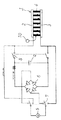
図1は請求項1,2の発明の実施形態を示す図である。図中、1はペルチェ素子であり、2枚の電極2,3の間にP形及びN形の半導体素子4を多数配置し、閉回路を構成したものである。このペルチェ素子1に接続される電源装置は、以下に説明するとおり直流と交流とに切り替え可能となっている。
【0009】
5は商用の交流電源であり、6は整流用のダイオードブリッジである。これらの間に設けられた切り替えスイッチ7を図の上側に切り替え、スイッチ8をオンにすると直流がペルチェ素子1に流れ、従来通りに片側の電極2が吸熱面となり、反対側の電極3が放熱面となる。このため、吸熱面側にヒートシンクを設けて盤内に配置すれば、冷却装置として機能する。
【0010】
また、切り替えスイッチ7を図の下側に切り替えれば、交流がペルチェ素子1に流れる。このときにはスイッチ8はオフとなるよう、切り替えスイッチ7と連動式としておくことが好ましい。このようにしてペルチェ素子1に交流電流を通電すると、ペルチェ素子1の半導体素子4の全体がジュール熱により緩やかに発熱する。このため、ペルチェ素子1に結露検出用のセンサ10を取り付け、結露が検出されたときに自動的に電源を交流に切り替えれば、ペルチェ素子1の結露を蒸発させることができる。 しかもこのジュール熱による加熱は全体が均一に発熱するうえに、従来の直流通電方向の反転方式のように急激な温度変化を伴わないので、ペルチェ素子1を劣化させることがない。
【0011】
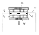
図2は請求項3の発明の実施形態を示す図である。図示のように盤内と盤外を区画する隔壁12にペルチェ素子1が取り付けられており、両側にヒートシンク13,14とファン15,16が配置されている。図示されていないが、このペルチェ素子1の電源装置は直流と交流とに切り替え可能となっている。
【0012】
通常運転時には、両側のファン15,16を動作させて盤内側から吸熱した熱量を盤外に放熱しているが、盤内温度が低下した場合には図示しない温度センサにより電源を交流に切り替え、前記したようにジュール熱を発生させる。また放熱側のファン15を停止する。この結果、ペルチェ素子1で発生したジュール熱は盤外側には放出されず、ファン16によって盤内側に送られるので、ペルチェ素子1をヒータとして利用した盤内保温が可能となる。この場合にも、従来の直流通電方向の反転方式のように急激な温度変化を伴わないので、ペルチェ素子1を劣化させることがない。
【0013】
【発明の効果】
以上に説明したように、請求項1,2の発明によれば、ペルチェ素子の劣化を招くことなく、結露によるペルチェ式冷却装置の故障を防止することができる。また請求項1,3の発明によれば、ペルチェ素子の劣化を招くことなく、ペルチェ式冷却装置をヒータとしても使用することができる。しかもペルチェ素子自体の構造を複雑化させることもない。このため本発明は、配電盤、分電盤などの電気電子機器収納盤の冷却手段として好適なものであるが、その他の用途にも適用できることはいうまでもない。
【図面の簡単な説明】
【図1】第1の実施形態を示す配線図である。
【図2】第2の実施形態を示す断面図である。
【符号の説明】
1 ペルチェ素子
2 電極
3 電極
4 半導体素子
5 交流電源
6 ダイオードブリッジ
7 切り替えスイッチ
8 スイッチ
9 コンデンサ
10 結露検出用のセンサ
12 隔壁
13 ヒートシンク
14 ヒートシンク
15 ファン
16 ファン[0001]
TECHNICAL FIELD OF THE INVENTION
The present invention relates to a Peltier-type cooling device that can be used as a cooling means for an electric / electronic equipment storage panel and the like, and a method of using the same.
[0002]
[Prior art]
[Patent Document 1] Japanese Patent Publication No. 3-59641 [Patent Document 2] Japanese Utility Model Publication No. 41-18988 [0003]
As disclosed in
[0004]
However, especially in the case of an outdoor-installed panel, when the outside air temperature decreases, the surface temperature on the heat absorption side of the Peltier element decreases to below the dew point, which may cause dew condensation. When the dew condensation water accumulates inside the electrode, there is a problem that the electrode is short-circuited or rusted and easily causes a failure. Further, in the winter season or the like, the temperature inside the panel may be too low, and it may be necessary to provide a separate heater for heating.
[0005]
Therefore,
[0006]
[Problems to be solved by the invention]
The present invention has been made to solve the above-mentioned conventional problems, and a first object of the present invention is to prevent a failure due to dew condensation without causing deterioration of the Peltier element and complicated structure. An object of the present invention is to provide a Peltier cooling device and a method of using the same. A second object of the present invention is to provide a Peltier-type cooling device that can be used as a heater without deteriorating the Peltier element and complicating the structure, and a method of using the same.
[0007]
[Means for Solving the Problems]
According to a first aspect of the present invention, there is provided a Peltier-type cooling device, wherein the Peltier device is connected to a power supply device that can switch between DC and AC. The invention according to
[0008]
BEST MODE FOR CARRYING OUT THE INVENTION
Hereinafter, preferred embodiments of the present invention will be described.
FIG. 1 is a diagram showing an embodiment of the first and second aspects of the present invention. In the figure,
[0009]
Reference numeral 5 denotes a commercial AC power supply, and
[0010]
If the
[0011]
FIG. 2 is a diagram showing an embodiment of the third aspect of the present invention. As shown in the drawing, a
[0012]
During normal operation, the
[0013]
【The invention's effect】
As described above, according to the first and second aspects of the present invention, it is possible to prevent the Peltier-type cooling device from malfunctioning due to condensation without deteriorating the Peltier device. Further, according to the first and third aspects of the present invention, the Peltier cooling device can be used as a heater without deteriorating the Peltier element. Moreover, the structure of the Peltier element itself is not complicated. For this reason, the present invention is suitable as a cooling means for electrical and electronic equipment storage boards such as a switchboard and a distribution board, but it goes without saying that the present invention can be applied to other uses.
[Brief description of the drawings]
FIG. 1 is a wiring diagram illustrating a first embodiment.
FIG. 2 is a cross-sectional view illustrating a second embodiment.
[Explanation of symbols]
REFERENCE SIGNS
Claims (3)
Priority Applications (1)
| Application Number | Priority Date | Filing Date | Title |
|---|---|---|---|
| JP2002356450A JP2004190884A (en) | 2002-12-09 | 2002-12-09 | Peltier-type cooling device and method of using the same |
Applications Claiming Priority (1)
| Application Number | Priority Date | Filing Date | Title |
|---|---|---|---|
| JP2002356450A JP2004190884A (en) | 2002-12-09 | 2002-12-09 | Peltier-type cooling device and method of using the same |
Publications (1)
| Publication Number | Publication Date |
|---|---|
| JP2004190884A true JP2004190884A (en) | 2004-07-08 |
Family
ID=32756793
Family Applications (1)
| Application Number | Title | Priority Date | Filing Date |
|---|---|---|---|
| JP2002356450A Pending JP2004190884A (en) | 2002-12-09 | 2002-12-09 | Peltier-type cooling device and method of using the same |
Country Status (1)
| Country | Link |
|---|---|
| JP (1) | JP2004190884A (en) |
Cited By (6)
| Publication number | Priority date | Publication date | Assignee | Title |
|---|---|---|---|---|
| JP2007198718A (en) * | 2005-12-27 | 2007-08-09 | Toppan Printing Co Ltd | Temperature control method |
| JP2009158814A (en) * | 2007-12-27 | 2009-07-16 | Fujitsu Ltd | Temperature control device |
| CN104343713A (en) * | 2014-01-20 | 2015-02-11 | 上海新时达电气股份有限公司 | Failure detection circuit of alternating current fan |
| CN107732730A (en) * | 2017-11-28 | 2018-02-23 | 天津城建大学 | A kind of power distribution cabinet dehumidification system based on semiconductor chilling plate |
| CN111884084A (en) * | 2020-08-04 | 2020-11-03 | 南安市工业学校 | Electrical control cabinet with heat dissipation function and use method thereof |
| DE102020212040A1 (en) | 2020-09-24 | 2022-03-24 | Mahle International Gmbh | Process for operating a heat exchanger |
-
2002
- 2002-12-09 JP JP2002356450A patent/JP2004190884A/en active Pending
Cited By (6)
| Publication number | Priority date | Publication date | Assignee | Title |
|---|---|---|---|---|
| JP2007198718A (en) * | 2005-12-27 | 2007-08-09 | Toppan Printing Co Ltd | Temperature control method |
| JP2009158814A (en) * | 2007-12-27 | 2009-07-16 | Fujitsu Ltd | Temperature control device |
| CN104343713A (en) * | 2014-01-20 | 2015-02-11 | 上海新时达电气股份有限公司 | Failure detection circuit of alternating current fan |
| CN107732730A (en) * | 2017-11-28 | 2018-02-23 | 天津城建大学 | A kind of power distribution cabinet dehumidification system based on semiconductor chilling plate |
| CN111884084A (en) * | 2020-08-04 | 2020-11-03 | 南安市工业学校 | Electrical control cabinet with heat dissipation function and use method thereof |
| DE102020212040A1 (en) | 2020-09-24 | 2022-03-24 | Mahle International Gmbh | Process for operating a heat exchanger |
Similar Documents
| Publication | Publication Date | Title |
|---|---|---|
| US5375421A (en) | Portable thermoelectric dehumidifier | |
| KR100726190B1 (en) | Heating mat using a warm water | |
| WO2013042553A1 (en) | Cooling device for housing | |
| JPH08148189A (en) | Battery temperature control device for electric vehicles | |
| KR101179041B1 (en) | LCD and LED display board applying air conditoning system with cooling module | |
| JP5486434B2 (en) | Power converter | |
| JP2020136290A (en) | Laser oscillator with improved dehumidification function | |
| JP2004190884A (en) | Peltier-type cooling device and method of using the same | |
| WO2019150560A1 (en) | Power conversion device | |
| KR101532514B1 (en) | A compact duhumidifier using thermoelectric element | |
| WO2006025689A1 (en) | Cooling device for computer using thermoelectric element, air-cooling kit and duct | |
| JP2004056846A (en) | Inverter device | |
| JP2012163285A (en) | Outdoor unit of air conditioner | |
| KR200297811Y1 (en) | Cooling and moisture removal device | |
| KR200261263Y1 (en) | Thermoelectric Module Computer Case | |
| KR20130013420A (en) | Closed circuit television camera apparatus having defrosting function | |
| JP3590325B2 (en) | Cooling device for electronic components | |
| JP3209615B2 (en) | Air conditioner refrigerant heating outdoor unit | |
| KR100722882B1 (en) | Corrosion prevention structure of blower motor | |
| KR200272299Y1 (en) | Constant temperature pyrostat and thermohygrostat using thermoelectric module | |
| JPH08306225A (en) | Dimming system | |
| JPH0637989B2 (en) | Electronic dehumidifier | |
| KR100616441B1 (en) | Blowing motor speed controller | |
| JP4594189B2 (en) | Heating element cooling device | |
| JPS6192174A (en) | Inverter |
Legal Events
| Date | Code | Title | Description |
|---|---|---|---|
| A621 | Written request for application examination |
Free format text: JAPANESE INTERMEDIATE CODE: A621 Effective date: 20050531 |
|
| A977 | Report on retrieval |
Free format text: JAPANESE INTERMEDIATE CODE: A971007 Effective date: 20080704 |
|
| A131 | Notification of reasons for refusal |
Free format text: JAPANESE INTERMEDIATE CODE: A131 Effective date: 20080708 |
|
| A521 | Request for written amendment filed |
Free format text: JAPANESE INTERMEDIATE CODE: A523 Effective date: 20080904 |
|
| A131 | Notification of reasons for refusal |
Free format text: JAPANESE INTERMEDIATE CODE: A131 Effective date: 20090220 |
|
| A521 | Request for written amendment filed |
Free format text: JAPANESE INTERMEDIATE CODE: A523 Effective date: 20090420 |
|
| A02 | Decision of refusal |
Free format text: JAPANESE INTERMEDIATE CODE: A02 Effective date: 20091204 |