JP2004190886A - Absorption refrigerating machine and absorption refrigerating system - Google Patents
Absorption refrigerating machine and absorption refrigerating system Download PDFInfo
- Publication number
- JP2004190886A JP2004190886A JP2002356475A JP2002356475A JP2004190886A JP 2004190886 A JP2004190886 A JP 2004190886A JP 2002356475 A JP2002356475 A JP 2002356475A JP 2002356475 A JP2002356475 A JP 2002356475A JP 2004190886 A JP2004190886 A JP 2004190886A
- Authority
- JP
- Japan
- Prior art keywords
- condenser
- refrigerant
- evaporator
- absorber
- generator
- Prior art date
- Legal status (The legal status is an assumption and is not a legal conclusion. Google has not performed a legal analysis and makes no representation as to the accuracy of the status listed.)
- Withdrawn
Links
- 238000010521 absorption reaction Methods 0.000 title claims abstract description 79
- 239000003507 refrigerant Substances 0.000 claims abstract description 93
- 238000010438 heat treatment Methods 0.000 claims abstract description 30
- 239000002826 coolant Substances 0.000 claims abstract description 29
- 239000007788 liquid Substances 0.000 claims abstract description 22
- 239000006096 absorbing agent Substances 0.000 claims description 88
- 239000002250 absorbent Substances 0.000 claims description 18
- 230000002745 absorbent Effects 0.000 claims description 18
- 239000000446 fuel Substances 0.000 claims description 17
- 238000005057 refrigeration Methods 0.000 claims description 13
- 238000001816 cooling Methods 0.000 claims description 10
- 239000012141 concentrate Substances 0.000 claims 1
- 238000004519 manufacturing process Methods 0.000 abstract 1
- XLYOFNOQVPJJNP-UHFFFAOYSA-N water Substances O XLYOFNOQVPJJNP-UHFFFAOYSA-N 0.000 description 93
- 229910001868 water Inorganic materials 0.000 description 93
- 239000000243 solution Substances 0.000 description 71
- 239000000498 cooling water Substances 0.000 description 57
- 238000001704 evaporation Methods 0.000 description 16
- 230000008020 evaporation Effects 0.000 description 14
- 239000007789 gas Substances 0.000 description 14
- 238000010586 diagram Methods 0.000 description 11
- 238000009833 condensation Methods 0.000 description 7
- 230000005494 condensation Effects 0.000 description 7
- 230000000052 comparative effect Effects 0.000 description 6
- 230000007423 decrease Effects 0.000 description 5
- QGZKDVFQNNGYKY-UHFFFAOYSA-N Ammonia Chemical compound N QGZKDVFQNNGYKY-UHFFFAOYSA-N 0.000 description 4
- AMXOYNBUYSYVKV-UHFFFAOYSA-M lithium bromide Chemical compound [Li+].[Br-] AMXOYNBUYSYVKV-UHFFFAOYSA-M 0.000 description 4
- 239000002918 waste heat Substances 0.000 description 3
- 229910021529 ammonia Inorganic materials 0.000 description 2
- 239000012809 cooling fluid Substances 0.000 description 2
- 239000012530 fluid Substances 0.000 description 2
- 238000005192 partition Methods 0.000 description 2
- 239000002699 waste material Substances 0.000 description 2
- 239000002351 wastewater Substances 0.000 description 2
- 238000004378 air conditioning Methods 0.000 description 1
- 238000009835 boiling Methods 0.000 description 1
- 239000012267 brine Substances 0.000 description 1
- KYKAJFCTULSVSH-UHFFFAOYSA-N chloro(fluoro)methane Chemical compound F[C]Cl KYKAJFCTULSVSH-UHFFFAOYSA-N 0.000 description 1
- 230000006835 compression Effects 0.000 description 1
- 238000007906 compression Methods 0.000 description 1
- 230000000694 effects Effects 0.000 description 1
- 230000005484 gravity Effects 0.000 description 1
- 239000000203 mixture Substances 0.000 description 1
- 238000010248 power generation Methods 0.000 description 1
- 230000008929 regeneration Effects 0.000 description 1
- 238000011069 regeneration method Methods 0.000 description 1
- HPALAKNZSZLMCH-UHFFFAOYSA-M sodium;chloride;hydrate Chemical compound O.[Na+].[Cl-] HPALAKNZSZLMCH-UHFFFAOYSA-M 0.000 description 1
- 238000011144 upstream manufacturing Methods 0.000 description 1
Images


Classifications
-
- Y—GENERAL TAGGING OF NEW TECHNOLOGICAL DEVELOPMENTS; GENERAL TAGGING OF CROSS-SECTIONAL TECHNOLOGIES SPANNING OVER SEVERAL SECTIONS OF THE IPC; TECHNICAL SUBJECTS COVERED BY FORMER USPC CROSS-REFERENCE ART COLLECTIONS [XRACs] AND DIGESTS
- Y02—TECHNOLOGIES OR APPLICATIONS FOR MITIGATION OR ADAPTATION AGAINST CLIMATE CHANGE
- Y02A—TECHNOLOGIES FOR ADAPTATION TO CLIMATE CHANGE
- Y02A30/00—Adapting or protecting infrastructure or their operation
- Y02A30/27—Relating to heating, ventilation or air conditioning [HVAC] technologies
-
- Y—GENERAL TAGGING OF NEW TECHNOLOGICAL DEVELOPMENTS; GENERAL TAGGING OF CROSS-SECTIONAL TECHNOLOGIES SPANNING OVER SEVERAL SECTIONS OF THE IPC; TECHNICAL SUBJECTS COVERED BY FORMER USPC CROSS-REFERENCE ART COLLECTIONS [XRACs] AND DIGESTS
- Y02—TECHNOLOGIES OR APPLICATIONS FOR MITIGATION OR ADAPTATION AGAINST CLIMATE CHANGE
- Y02B—CLIMATE CHANGE MITIGATION TECHNOLOGIES RELATED TO BUILDINGS, e.g. HOUSING, HOUSE APPLIANCES OR RELATED END-USER APPLICATIONS
- Y02B30/00—Energy efficient heating, ventilation or air conditioning [HVAC]
- Y02B30/62—Absorption based systems
Landscapes
- Sorption Type Refrigeration Machines (AREA)
Abstract
Description
【0001】
【発明の属する技術分野】
本発明は、吸収冷凍機及び吸収冷凍機を備える冷凍システムに関し、特に温度差の大きい排熱を有効に使って、効率良く冷熱を製造できる吸収冷凍機及びそのような冷凍機を備える冷凍システムに関するものである。
【0002】
【従来の技術】
従来から、コージェネレーションシステムで発電に伴って出される排ガスや排温水によって運転する吸収冷凍機があった。ガスエンジンやガスタービンから出される排ガスは、その温度が200〜300℃と比較的高温であるため、この排ガスで150℃程度の蒸気を発生させたり、あるいは排ガスを直接投入するなどして、2重効用の吸収冷凍機を運転することが一般に知られている。また、ガスエンジン/ガソリンエンジン/ディーゼルエンジン等のジャケット温水や、太陽熱集熱器で得られる温水は、その温度が80〜90℃であり、単効用の吸収冷凍機や、ジェネリンク、二重効用吸収冷凍機などの熱源として利用する装置が一般に知られている(例えば、特許文献1参照)。
【0003】
【特許文献1】
特開平08−54156号公報(図1、図2)
【0004】
【発明が解決しようとする課題】
しかしながら、以上のような従来の装置では、出入り口の温度差が大きい排熱を利用することが困難であり、一方エンジンや燃料電池からの排温水は、それ自身がエンジンや燃料電池の冷却水であるため、低い温度まで冷却して戻す必要がある。また排温水の搬送動力を低減するためにも、循環する熱媒(加熱用流体)の出入り口温度差を大きくしたいという要請があるが、従来の装置ではこれに対応しきれていなかった。
【0005】
そこで本発明は、加熱媒体の出入り口温度差が大きい場合に、その排熱を有効に使って、効率良く冷熱を製造できる吸収冷凍機及びそのような吸収冷凍機を備える吸収冷凍システムを提供することを目的としている。
【0006】
【課題を解決するための手段】
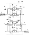
上記目的を達成するために、請求項1に係る発明による吸収冷凍機は、例えば図1に示されるように、吸収液を加熱媒体31wで加熱して濃縮する第1の発生器G1と;第1の発生器G1で発生した冷媒蒸気を第1の冷却媒体16wで冷却し凝縮する第1の凝縮器C1と;第1の発生器G1で濃縮された吸収液を加熱媒体31wで加熱してさらに濃縮する第2の発生器G2と;第2の発生器G2で発生した冷媒蒸気を第1の冷却媒体16wで冷却し凝縮する第2の凝縮器C2とを備え;加熱媒体31wを、第2の発生器G2と第1の発生器G1に、この順に直列に流し、第1の冷却媒体16wを、第1の凝縮器C1と第2の凝縮器C2に、この順に直列に流すように構成される。
【0007】
典型的には、第1の凝縮器C1で凝縮された冷媒と第2の凝縮器C2で凝縮された冷媒とを受け入れて、該冷媒を蒸発させて冷熱媒体41wを冷却する蒸発器Eと、第2の発生器G2で濃縮された吸収液を受け入れて、蒸発器Eで蒸発した冷媒を吸収する吸収器Aとを備える。また吸収器Aから第1の発生器G1に送られる吸収液と第2の発生器G2から吸収器Aに戻る吸収液との間で熱交換させる熱交換器10を備える。発生器と凝縮器は、第1と第2に限らず、第3以上を備えてもよい。
【0008】
このように構成すると、加熱媒体を、第2の発生器と第1の発生器に、この順に直列に流し、第1の冷却媒体を、第1の凝縮器と第2の凝縮器に、この順に直列に流すように構成するので、加熱媒体の出入り口温度差が大きい場合に、その排熱を有効に使うことができる。
【0009】
また請求項2に記載のように、また例えば図3に示すように、請求項1に記載の吸収冷凍機では、第1の凝縮器C1で凝縮された冷媒と第2の凝縮器C2で凝縮された冷媒とを受け入れて、該冷媒を蒸発させて冷熱媒体41wを冷却する第1の蒸発器E1と;第1の凝縮器C1で凝縮された冷媒と第2の凝縮器C2で凝縮された冷媒とを受け入れて、該冷媒を蒸発させて冷熱媒体を冷却する第2の蒸発器E2と;第2の発生器G2で濃縮された吸収液を受け入れて、該吸収液を第2の冷却媒体15wで冷却しながら該吸収液で第1の蒸発器E1で蒸発した冷媒を吸収する第1の吸収器A1と;第1の吸収器A1で冷媒を吸収した吸収液を受け入れて、該吸収液を第2の冷却媒体15wで冷却しながら該吸収液で第2の蒸発器E2で蒸発した冷媒を吸収する第2の吸収器A2とを備え;冷熱媒体41wを、第2の蒸発器E2と第1の蒸発器E1に、この順に直列に流すように構成してもよい。
【0010】
典型的には、第2の冷却媒体15wを、第1の吸収器A1と第2の吸収器A2に、この順に直列に流す。また典型的には、第2の吸収器A2から第1の発生器G1に送られる吸収液と第2の発生器G2から第1の吸収器A1に戻る吸収液との間で熱交換させる熱交換器10を備える。ここで、吸収器と蒸発器は、第1と第2に限らず、第3以上を備えてもよい。
また第1の冷却媒体と第2の冷却媒体は、同じ系統から供給してもよい。典型的には、例えば同じ冷却塔から供給される冷却水とする。
【0011】
上記目的を達成するために、請求項3に係る発明による吸収冷凍システムは、例えば図1、図2に示すように、請求項1又は請求項2に記載の吸収冷凍機101a、102aと;加熱媒体31wを供給する加熱源3とを備える。
【0012】
また請求項4に記載のように、請求項3に記載の吸収冷凍システムでは、前記加熱源は、燃料電池としてもよい。
【発明の実施の形態】
以下、本発明の実施の形態について、図面を参照して説明する。なお、各図において互いに同一あるいは相当する部材には同一符号あるいは類似符号を付し、重複した説明は省略する。
【0013】
図1のフロー図を参照して、本発明の第1の実施の形態である吸収冷凍機とそれを備える吸収冷凍システムを説明する。本吸収冷凍機101aと加熱源としての外部熱源装置、具体的には燃料電池3とを含んで、本発明の実施の形態である吸収冷凍システム101が構成される。吸収冷凍機101aの作業媒体としては、吸収剤と冷媒の組合せが用いられる。本実施の形態では、各種吸収冷凍機で現在最も広く用いられている、臭化リチウムを吸収剤として使用し、本発明の冷媒として水を使用する。しかしながらこれに限らず、例えば水を吸収剤として、アンモニアを冷媒として使用してもよい。
【0014】
本実施の形態で使用する吸収冷凍機101aは、単効用吸収冷凍機に準ずる吸収冷凍機である。再生器を複数備えるものの、第1の再生器で蒸発した冷媒蒸気を第2再生器の加熱媒体として用いる二重効用吸収冷凍機とは区別される。吸収冷凍機101aは、冷媒としての水を蒸発させて、冷熱源媒体としての冷水41wを冷却する蒸発器Eを備える。蒸発器Eは伝熱部を有するが、本実施の形態では、伝熱部として冷水伝熱管41aを採用している。蒸発器Eでは、冷水伝熱管41aの内部を流れる冷水41wを冷却する。蒸発器Eには、冷水41wを供給する冷水配管41が接続されている。
【0015】
さらに吸収冷凍機101aは、蒸発器Eで蒸発した冷媒を吸収する吸収器Aと、吸収器Aから送られる吸収液(吸収剤と冷媒の混合物、以下適宜「溶液」とも呼ぶ)を加熱して冷媒ガスを発生させる第1の再生器G1と、第1の再生器G1である程度まで濃縮された吸収液を受け入れて、加熱して冷媒ガスを発生させる第2の再生器G2を備える。さらに吸収冷凍機101aは、第1の再生器G1で発生した冷媒ガスを凝縮して、凝縮した冷媒液を蒸発器Eに送る第1の凝縮器C1と、第2の再生器G2で発生した冷媒ガスを凝縮して、凝縮した冷媒液を蒸発器Eに送る第2の凝縮器C2とを備える。
【0016】
第1の再生器G1と第1の凝縮器C1とは第1の缶胴に収納され、第2の再生器G2と第2の凝縮器C2とは、第1の缶胴とは別の第2の缶胴に収納されている。第1の缶胴と第2の缶胴とは、別体に構成されるか、仕切壁により隔離されている。したがって、両缶胴内の圧力は互いに異ならせることができる。
【0017】
吸収器Aは伝熱部として冷却水伝熱管15aを有し、この内部を流れる第2の冷却媒体としての冷却流体、具体的には冷却水15wで、冷却水伝熱管15aの外部に散布される溶液を冷却する。
再生器G1、G2は伝熱部としてそれぞれ温水伝熱管31a、31bを有し、この内部を流れる外部熱源媒体としての加熱用流体、具体的には温水で、それぞれ温水伝熱管31a、31bの外部に溜まっている、又は温水伝熱管31a、31b上に散布されている溶液を加熱する。
凝縮器C1、C2は伝熱部としてそれぞれ冷却水伝熱管16a、16bを有し、この内部を流れる第1の冷却媒体としての冷却流体、具体的には冷却水16wで、冷却水伝熱管16a、16bの外部に存在する冷媒ガスから熱を奪い凝縮させる。
以下、冷水伝熱管41a、冷却水伝熱管15a、16a、16b、温水伝熱管31a、31bは、紛らわしくない限り、適宜単に伝熱管41a、伝熱管15a、16a、16b、伝熱管31a、31bという。
【0018】
吸収器Aには、冷却水15wを供給する冷却水配管15が接続されており、第1、第2の再生器G1、G2には、温水31wを供給する温水配管31が接続されており、 第1、第2の凝縮機C1、C2には、冷却水16wを供給する冷却水配管16が、それぞれ接続されている。
また、第1の再生器G1と第2の再生器G2とは、第1の再生器G1である程度再生された吸収液である中間濃度の吸収液を第2の再生器G2に戻す中間濃度溶液配管13aで接続され、第2の再生器G2と吸収器Aは、第2の再生器G2で再生された溶液を吸収器Aに戻す濃溶液配管13bで接続されている。また吸収器Aと第1の再生器G1とは、吸収器Aで冷媒を吸収して希溶液となった溶液を第1の再生器G1に送る希溶液配管14で接続されている。濃溶液配管13bと希溶液配管14には、溶液熱交換器10が挿入配置されており、第2の再生器G2から吸収器Aに戻される濃溶液と吸収器Aから第1の再生器G1に送られる希溶液との間で熱交換を行うように構成されている。
【0019】
また第1の再生器G1は第2の再生器G2よりも高所に、第2の再生器G2は吸収器Aよりも高所に配置されており、また両再生器G1、G2の作動圧力は吸収器Aのそれよりも高い。したがって、希溶液配管14には溶液ポンプ11が挿入配置されており、希溶液配管14を通して吸収器Aから第1の再生器G1に溶液を送ることを可能としている。中間濃度溶液配管13a、濃溶液配管13を通して行われる、第1、第2の再生器G1、G2から吸収器Aへの中間濃度溶液と濃溶液の移送は重力及び各機器間の圧力差により行われる。
【0020】
吸収冷凍機101aは、さらに第1の凝縮器C1で凝縮した冷媒液を蒸発器Eに戻す冷媒配管12aと、第2の凝縮器C2で凝縮した冷媒液を蒸発器Eに戻す冷媒配管12bとを備える。本図では、冷媒配管12a、12bは冷媒配管12に合流した上で蒸発器Eに戻す場合が示されているが、冷媒配管12a、12bを別々に蒸発器Eに接続して、冷媒液を別々に戻してもよい。
【0021】
吸収冷凍機101aの外部には、冷水負荷としての室内空調機4があり、室内空調機4と蒸発器Eとは、冷水配管41で接続されている。このような構成により、冷水配管41を流れる冷水41wは、室内空調機4と吸収圧縮冷凍装置101との間を循環するように構成されている。
【0022】
吸収冷凍機101aの外部には、外部熱源装置としての燃料電池3があり、燃料電池3と第2の再生器G2、第1の再生器G1とは、温水配管31で接続されている。第1の再生器G2の伝熱管31bと第1の再生器G1の伝熱管31aとは、温水配管31により、温水の流れの上流側からこの順番で直列に連結されている。したがって、温水配管31を流れる温水31wは、燃料電池3、第2の再生器G2の温水伝熱管31b、第1の再生器G1の温水伝熱管31aの順番で流れ、燃料電池3に戻る。このようにして、温水31wは燃料電池3と吸収冷凍機101aの間を循環するように構成されている。
【0023】
引き続き図1を参照して、第1の実施の形態中の吸収冷凍機101aのサイクル(2段再生サイクル)について説明する。蒸発器Eで冷水伝熱管41aを流れる冷水41wから熱を奪い蒸発した冷媒蒸気は、吸収器Aにて冷却水伝熱管15aを流れる冷却水15wで冷却されている溶液に吸収される。吸収器A中の溶液は、不図示のポンプにより冷水伝熱管15a上に散布される。散布された溶液は吸収器Aの底部に溜まり、再び前記ポンプにより吸い込まれ散布される。
【0024】
冷媒を吸収して吸収剤の濃度が低下した希溶液は、溶液ポンプ11によって溶液熱交換器10に送られ、そこで第2の再生器G2から戻る高温の濃溶液と熱交換し、昇温して第1の再生器G1に入る。第1再生器G1では温水伝熱管31aを流れる温水31wによって溶液が加熱され、冷媒蒸気を放出して濃縮され、中濃度の溶液になる。この中濃度の溶液は第2の再生器G2に入り、温水伝熱管31bを流れる温水31wによって加熱され、冷媒蒸気を放出して濃縮されて濃溶液となる。この濃溶液は溶液熱交換器10にて熱回収され温度が低下して吸収器Aに戻る。一方、第1の発生器G1で発生した冷媒蒸気は、第1の凝縮器C1で冷却水伝熱管16aを流れる冷却水16wにより冷却され凝縮する。同様に、第2の発生器G2で発生した冷媒蒸気は、第2の凝縮器C2で冷却水伝熱管16bを流れる冷却水16により冷却され凝縮する。これら凝縮した冷媒液は合流して蒸発器Eに戻り、サイクルを一巡する。
【0025】
冷却水16wは、第1の凝縮器C1から第2の凝縮器C2の順に通水する。まず第1の凝縮器C1に入った冷却水は、冷却水伝熱管16aで、第1の再生器G1で発生した冷媒蒸気から凝縮熱を奪って温度が上昇する。続いて第2の凝縮器C2に入った冷却水16wは、冷却水伝熱管16bで、第2の再生器G2で発生した冷媒蒸気から凝縮熱を奪ってさらに温度が上昇して出て行く。このため、第2の凝縮器C2より第1の凝縮器C1のほうが冷却水の温度が低いので、冷媒蒸気の凝縮温度が低くなる。すなわち凝縮圧力が小さくなる。第1の再生器G1と第1の凝縮器C1、および第2の再生器G2と第2の凝縮器C2はそれぞれ連通しており圧力が等しいので、第2の再生器G2と第2の凝縮器C2の缶胴より、第1の再生器G1と第1の凝縮器C1の缶胴のほうが、内圧が小さくなる。
【0026】
排温水源である燃料電池3から送られてきた温水31wは、前述のように、第2の再生器G2から第1の再生器G1の順に通水する。まず第2の再生器G2に入った温水31wは温水伝熱管31bで溶液を加熱し、自身は熱を失い温度が低下する。続いて第1の再生器G1に入った温水31wは温水伝熱管31aで溶液を加熱し、さらに温度が低下して燃料電池3に戻る。
【0027】
上述のように、第1の再生器G1と第1の凝縮器C1の缶胴は、通常の単効用サイクルの再生器/凝縮器缶胴に比べて内圧が低いので、第1の再生器G1の溶液の沸点が通常の単効用吸収冷凍機の場合よりも低くなる。すなわち再生器を加熱する熱源の温度が低くても良いため、温水の再生器出口温度が低くできる。したがって、燃料電池3のように、通常の単効用吸収冷凍機では使用し難い比較的温度の低い温水しか供給できない排温水源との組み合わせに適している。
【0028】
図2のデューリング線図を参照して、第1の実施の形態の吸収冷凍機101aの作用を説明する。各線図の横軸は溶液の温度、縦軸は冷媒の飽和温度を表している。以下の温度は具体的な比較例(a)と実施例(b)として、温水の入り/戻り温度が75/65℃、冷却水の入り/戻り温度が30/35℃の場合のものを示す。例示する具体的な温度は(カッコ)内に示す。
【0029】
(a)は比較例としての単効用サイクルを線図で表したもので、再生器の圧力は冷媒の凝縮温度Tc(36℃)によって決められる。また、再生器の濃溶液温度Tgは、熱源の温水の再生器出口温度(65℃)から熱交換器での温度差(1℃)を差し引いたものになる(65−1=64℃)。一方、吸収器の希溶液温度Ta(36℃)によって冷媒の蒸発圧力すなわち蒸発温度Te(15.5℃)が決められる。蒸発器でつくられる冷水の温度は、冷媒の蒸発温度に熱交換器での温度差(1℃)を加えたものになる(15.5+1=16.5℃)。
【0030】
(b)は図1の吸収冷凍機101aのサイクルを線図に表したもので、第1の再生器G1の圧力は第1の凝縮器C1の凝縮温度Tc1(33.5℃)によって、また、第2の再生器G2の圧力は第2の凝縮器C2の凝縮温度Tc2(36℃)によって、それぞれ決められる。
【0031】
第1、第2の再生器G1、G2の溶液温度Tg1、Tg2は、各々の再生器の温水出口温度(65℃、70℃)から、熱交換器での温度差(1℃)を差し引いたものになるため、それぞれTg1(64℃)、Tg2(69℃)となり、(a)に示す単効用サイクルに比べて濃溶液と希溶液の濃度幅が大きくなる。これにより吸収器の希溶液温度Ta(36℃)に対して冷媒蒸発温度はTe(10.5℃)となり、蒸発器でつくられる冷水の温度は、Teに熱交換器での温度差(1℃)を加えたものになる(10.5+1=11.5℃)。すなわち(a)の単効用サイクルに比べて冷水温度を低くすることができる(16.5−11.5=5℃)。
【0032】
次に図3のフロー図及び図4のデューリング線図を参照して、本発明の第2の実施の形態の吸収冷凍機102a及び吸収冷凍システム102を説明する。
【0033】
第2の実施の形態の吸収冷凍機102aは、第1の実施の形態の吸収冷凍機101aとは次の点で相違する。すなわち、第1の実施の形態が蒸発器Eと吸収器Aを備えていたのに対して、第2の実施の形態は、互いに蒸発器同士が冷媒液の流れに対して直列に、また吸収器同士が吸収液の流れに対して直列に接続された、第1の蒸発器E1と第1の吸収器A1、第2の蒸発器E2と第2の吸収器A2を備えている。
第1の蒸発器E1と第1の吸収器A1とは第3の缶胴に収納され、第2の蒸発器E2と第2の吸収器A2とは、第3の缶胴とは別の第4の缶胴に収納されている。第3の缶胴と第4の缶胴とは、別体に構成されるか、仕切壁により隔離されている。したがって、両缶胴内の圧力は異ならせることができる。
【0034】
上述のように、第1の実施の形態の吸収冷凍機101aの蒸発器Eと吸収器Aが、第1の蒸発器E1と第1の吸収器A1、及び第2の蒸発器E2と第2の吸収器A2に置き換えられている。第1の吸収器A1と第2の吸収器A2とは、中間濃度溶液配管13cで接続されている。第2の吸収器A2には、第1の実施の形態の吸収器Aと同様に希溶液配管14が接続され溶液ポンプ11で希溶液を、第2の吸収器A2から第1の再生器G1に送るように構成されている。
【0035】
また冷却水配管15は、第1の吸収器A1の伝熱管15aと第2の吸収器A2の伝熱管15bとを直列に接続しており、伝熱管15aから伝熱管15bへと流れるように構成されている。
【0036】
冷媒配管12は、冷媒配管12cと12dとに分岐しており、冷媒配管12cは第1の蒸発器E1に、冷媒配管12dは第2の蒸発器E2に、それぞれ接続されている。
【0037】
また冷水配管41は、第2の蒸発器E2の伝熱管41bと第1の蒸発器E1の伝熱管41aとを直列に接続しており、伝熱管41bから伝熱管41aへと流れるように構成されている。
【0038】
第1再生器G1、第2再生器G2、第1凝縮器C1、第2凝縮器C2、溶液熱交換器10、溶液ポンプ11、冷媒配管12、中間濃度溶液配管13a、濃溶液配管13b、希溶液配管14、冷却水16、冷却水伝熱管16a、16b、温水配管31、温水伝熱管31a、31b、冷水配管41は、第1の実施の形態と同様であるので、重複した説明は省略する。排温水源である燃料電池3、室内空調機4も同様である。
【0039】
続けて、吸収冷凍機102aのサイクルについて説明する。第1の蒸発器E1で冷水伝熱管41aを流れる冷水41wから熱を奪い蒸発した冷媒蒸気は、第1の吸収器A1において冷却水伝熱管15aを流れる冷却水15で冷却されている濃溶液に吸収される。冷媒を吸収して吸収剤の濃度が低下した中濃度溶液は、中間濃度溶液配管13cを通して第2の吸収器A2に送られ、第2の蒸発器E2で冷水伝熱管41bを流れる冷水41wから熱を奪い蒸発した冷媒蒸気は、第2の吸収器A2において冷却水伝熱管15bを流れる冷却水15で冷却されている中濃度溶液に吸収される。冷媒を吸収して吸収剤の濃度が低下した希溶液は、溶液ポンプ11によって溶液熱交換器10に送られ、そこで第2の再生器G2から戻る高温の濃溶液と熱交換し、昇温して第1の再生器G1に入る。以降は第1の実施の形態と同じであるので重複した説明は省略する。
【0040】
2つの吸収器用の冷却水15wは、第1の吸収器A1から第2の吸収器A2の順に通水される。まず第1の吸収器A1に入った冷却水15wは、冷却水伝熱管15aで、第1の蒸発器E1で蒸発した冷媒蒸気の吸収熱で温度が上昇する。続いて第2の吸収器A2に入った冷却水15は、冷却水伝熱管15bで、第2の蒸発器E2で蒸発した冷媒蒸気の吸収熱でさらに温度が上昇して出て行く。このため、第2の吸収器A2より第1の吸収器A1のほうが冷却水の温度が低くかつ溶液の濃度が濃いため、冷媒蒸気を吸収する力が強くなり、冷媒の蒸発圧力が低くなる。第1の吸収器A1と第1の蒸発器E1、および第2の吸収器A2と第2の蒸発器E2はそれぞれ一つの缶胴内で連通しており圧力が等しいので、第2の吸収器A2と第2の蒸発器E2の缶胴より、第1の吸収器A1と第1の蒸発器E1の缶胴のほうが、内圧が低くなる。
【0041】
室内空調機4から送られてきた冷水41wは、第2の蒸発器E2から第1の蒸発器E1の順に通水される。まず第2の蒸発器E2に入った冷水41は冷水伝熱管41bで冷媒を蒸発させ、自身は熱を失い温度が低下する。続いて第1の蒸発器E1に入った冷水41は冷水伝熱管41aで冷媒を蒸発させ、さらに温度が低下して室内空調機4に戻る。
【0042】
上述のように、第1の吸収器A1と第1の蒸発器E1の缶胴は、通常の単効用サイクルの吸収器/蒸発器缶胴に比べて内圧が低いため、第1の蒸発器E1の冷媒の蒸発温度が低くなる。すなわち蒸発器E1で冷却される冷水の出口温度が低くできる。
【0043】
2つの凝縮器の冷却水16wおよび排温水源である燃料電池3からの温水31の流れは第1の実施の形態と同様である。
【0044】
図4のデューリング線図を参照して、第2の実施の形態の吸収冷凍機102aの作用を説明する。図2と同様に、(a)(b)各線図の横軸は溶液の温度、縦軸は冷媒の飽和温度を表している。以下の温度は具体的な比較例(a)と実施例(b)として、温水の入り/戻り温度が75/65℃、冷却水の入り/戻り温度が30/35℃の場合のものを示す。例示する具体的な温度は(カッコ)内に示す。
【0045】
(a)は比較例としての単効用サイクルを線図で表したもので、図2(a)と同様である。(b)は、吸収冷凍機102aのサイクルを線図に表したもので、第1の吸収器A1の温度Ta1によって第1の蒸発器E1の冷媒蒸発圧力すなわち冷媒蒸発温度Te1が決められる。同様に、第2の吸収器A2の温度Ta2によって第2の蒸発器E2の冷媒蒸発圧力すなわち冷媒蒸発温度Te2が決められる。再生器と凝縮器については図2(b)に示す第1の実施の形態と同様であるので説明を省略する。
【0046】
第1の吸収器A1の温度(33.5℃)は第2の吸収器A2の温度(36℃)より低いため、第1の蒸発器E1の冷媒蒸発温度Te1(6.5℃)は第2の蒸発器E2の冷媒蒸発温度Te2(10.5℃)より低くなり、蒸発器でつくられる冷水の温度はTe1に熱交換器での温度差(1℃)を加えたものとなる(6.5+1=7.5℃)。すなわち、蒸発器でつくられる冷水の温度を、図4(a)の通常の単効用サイクルよりTe−Te1に相当する温度だけ低くすることができる(16.5−7.5=9℃)。
【0047】
このように、冷却水の通水順序を変更することで、吸収冷凍機の特性を変えることができる。例えば、冷却水を第1の吸収器A1、第2の吸収器A2、第1の凝縮器C1、第2の凝縮器C2、の順に通水すると、吸収器および凝縮器の温度はTa1<Ta2<Tc1<Tc2となり、第1の吸収器A1の温度が低くなるので第1の吸収器A1/第1の蒸発器E1の缶胴の圧力が低くなり、第1の蒸発器E1の冷媒蒸発温度Te1が低くなるため、冷水出口温度を低くすることができる。
【0048】
また、冷却水を第1の凝縮器C1、第2の凝縮器C2、第1の吸収器A1、第2の吸収器A2、の順に通水すると、吸収器および凝縮器の温度はTc1<Tc2<Ta1<Ta2となり、第1の凝縮器C1の温度が低くなるので第1の凝縮器C1/第1再生器G1缶胴の圧力が低くなり、第1の再生器G1の濃溶液温度Tg1が低くなるため、熱源温水の第1の再生器出口温度を低くすることができる。
【0049】
さらに、冷却水を第1の吸収器A1と第2の吸収器A2および第1の凝縮器C1と第2の凝縮器C2に並列に通水すると、吸収器および凝縮器の温度はTc1=Ta1<Tc2=Ta2となり、第1の吸収器A1の温度が低く、かつ第1の凝縮器C1の温度が低くなるので、上記2者の特性を併せ持たせることができるため、冷水出口温度が低く、かつ熱源温水の再生器出口温度が低くすることができる。
【0050】
以上説明した本発明の実施の形態は、以下のような特徴を有する。
吸収冷凍機101a、102aの作動媒体はリチウムブロマイドと水、水とアンモニアに限らず、熱源の温度、欲しい冷熱媒体の温度、冷凍容量等に従って適切なものを選択すればよい。
加熱源としての外部熱源装置は、燃料電池に限らず、例えばガスタービンやガスエンジンなどであってもよい。排熱の形態も、温水に限らず、水蒸気、排ガス等であってもよい。
冷凍負荷は、冷房の室内機に限らず、例えば冷蔵・冷蔵庫やショーケース等であってもよい。 冷熱媒体は、冷水に限らず、例えばブラインやフロンなどの冷媒でもあってもよい。 各機器は1台に限らず複数であっても良い。
【0051】
以上説明した本発明の実施の形態は、従来の技術との関連において、以下のような利点を有する。本発明の実施の形態によれば、吸収冷凍機の再生器および凝縮器を複数に分割し、凝縮器に供給する冷却水を直列に利用、即ちカスケード利用することによって、各々の缶胴内の圧力を変えることができるため、冷却水温が低い凝縮器に対応する再生器の溶液温度が低くなる。 熱源温水を、冷却水温が高い凝縮器に対応する再生器から、冷却水温が低い凝縮器に対応する再生器に向かって流すことによって、熱源温水をより低温まで利用できるため、入口と出口の温度差が大きい熱源温水の持つエネルギーを高温から低温まで有効に利用することが可能になる。
また同様に、吸収器および蒸発器を複数に分割し、吸収器に供給する冷却水をカスケード利用することによって、各々の缶胴内の圧力を変えることができるため、冷却水温が低い吸収器に対応する蒸発器の冷媒蒸発温度が低くなる。冷水を、冷却水温が高い吸収器に対応する蒸発器から、冷却水温が低い吸収器に対応する蒸発器に向かって流すことによって、冷水をより低温まで冷却することが可能になる。
さらにこれらを組み合わせ、冷却水の通水順序を変えることによって、冷水温度の低いサイクルや、熱源温水をより低温まで利用できるサイクルなど、様々な特性のサイクルを得ることができる。
【0052】
【発明の効果】
以上のように本発明によれば、加熱媒体を、第2の発生器と第1の発生器に、この順に直列に流し、第1の冷却媒体を、第1の凝縮器と第2の凝縮器に、この順に直列に流すように構成するので、加熱媒体の出入り口温度差が大きい場合に、その排熱を有効に使うことができる吸収冷凍機を提供することが可能となる。
【図面の簡単な説明】
【図1】本発明の第1の実施の形態である吸収冷凍機及びそれを含む吸収冷凍システムのフロー図である。
【図2】比較例の単効用の吸収冷凍機と、図1に示す第1の実施の形態の吸収冷凍機のデューリング線図である。
【図3】本発明の第2の実施の形態である吸収冷凍機及びそれを含む吸収冷凍システムのフロー図である。
【図4】比較例の単効用の吸収冷凍機と、図3に示す第2の実施の形態の吸収冷凍機のデューリング線図である。
【符号の説明】
3 燃料電池
4 空調負荷
10 溶液熱交換器
11 溶液ポンプ
12 冷媒配管
13a 中間濃度溶液配管
13b 濃溶液配管
14 希溶液配管
15、16 冷却水配管
15a、16a 冷却水伝熱管
15w、16w 冷却水
31 温水配管
31w 温水
31a、31b 温水伝熱管
41 冷水配管
41a 冷水伝熱管
41w 冷水
101、102 吸収冷凍システム
101a、102a 吸収冷凍機
E 蒸発器
E1 第1の蒸発器
E2 第2の蒸発器
A 吸収器
A1 第1の吸収器
A2 第2の吸収器
G 再生器
G1 第1の再生器
G2 第2の再生器
C 凝縮器
C1 第1の凝縮器
C2 第2の凝縮器[0001]
TECHNICAL FIELD OF THE INVENTION
The present invention relates to an absorption chiller and a refrigeration system including the absorption chiller, and more particularly to an absorption chiller capable of efficiently producing cold heat by effectively using exhaust heat having a large temperature difference, and a refrigeration system including such a refrigerator. Things.
[0002]
[Prior art]
2. Description of the Related Art Conventionally, there has been an absorption refrigerator operated by exhaust gas or waste water discharged along with power generation in a cogeneration system. Exhaust gas emitted from a gas engine or a gas turbine has a relatively high temperature of 200 to 300 ° C., so that the exhaust gas generates steam at about 150 ° C. It is generally known to operate a heavy duty absorption refrigerator. The temperature of jacketed hot water such as gas engine / gasoline engine / diesel engine or hot water obtained by a solar heat collector is 80 to 90 ° C., and is a single-effect absorption refrigerator, Genelink, double-effect. A device used as a heat source such as an absorption refrigerator is generally known (for example, see Patent Document 1).
[0003]
[Patent Document 1]
JP-A-08-54156 (FIGS. 1 and 2)
[0004]
[Problems to be solved by the invention]
However, in the above-described conventional apparatus, it is difficult to use exhaust heat having a large temperature difference between an entrance and an exit.On the other hand, exhaust heat water from an engine or a fuel cell is itself cooling water for an engine or a fuel cell. Therefore, it is necessary to cool down to a low temperature and return. In addition, there is a demand for increasing the temperature difference between the inlet and the outlet of the circulating heat medium (heating fluid) in order to reduce the transport power of the waste hot water, but the conventional apparatus has not been able to cope with this.
[0005]
Therefore, the present invention provides an absorption refrigerator having an absorption refrigerator capable of efficiently producing cold heat by effectively using the waste heat when the temperature difference between the entrance and exit of the heating medium is large, and an absorption refrigerator having such an absorption refrigerator. It is an object.
[0006]
[Means for Solving the Problems]
To achieve the above object, an absorption refrigerator according to the first aspect of the present invention includes, as shown in FIG. 1, a first generator G1 for heating and concentrating an absorption liquid with a
[0007]
Typically, an evaporator E that receives the refrigerant condensed in the first condenser C1 and the refrigerant condensed in the second condenser C2 and evaporates the refrigerant to cool the
[0008]
With this configuration, the heating medium flows through the second generator and the first generator in series in this order, and the first cooling medium flows through the first condenser and the second condenser. Since it is configured to flow in series in order, when the temperature difference between the entrance and exit of the heating medium is large, the waste heat can be used effectively.
[0009]
Further, as described in claim 2 and, for example, as shown in FIG. 3, in the absorption refrigerator according to claim 1, the refrigerant condensed in the first condenser C1 and the refrigerant condensed in the second condenser C2. And a first evaporator E1 for evaporating the refrigerant to cool the
[0010]
Typically, the
Further, the first cooling medium and the second cooling medium may be supplied from the same system. Typically, it is, for example, cooling water supplied from the same cooling tower.
[0011]
In order to achieve the above object, an absorption refrigeration system according to the third aspect of the present invention includes, as shown in FIGS. 1 and 2, for example,
[0012]
Further, as described in
BEST MODE FOR CARRYING OUT THE INVENTION
Hereinafter, embodiments of the present invention will be described with reference to the drawings. In each of the drawings, the same or corresponding members are denoted by the same or similar reference numerals, and redundant description will be omitted.
[0013]
With reference to the flowchart of FIG. 1, an absorption refrigeration machine according to a first embodiment of the present invention and an absorption refrigeration system including the same will be described. The absorption refrigerating
[0014]
The
[0015]
Further, the
[0016]
The first regenerator G1 and the first condenser C1 are housed in a first can body, and the second regenerator G2 and the second condenser C2 are provided in a first can body different from the first can body. 2 cans. The first can body and the second can body are configured separately or separated by a partition wall. Therefore, the pressures in both can bodies can be different from each other.
[0017]
The absorber A has a cooling water
The regenerators G1 and G2 have hot water
The condensers C1 and C2 have cooling water
Hereinafter, the cold water
[0018]
A cooling
Further, the first regenerator G1 and the second regenerator G2 are an intermediate concentration solution for returning the intermediate concentration absorbent, which is the absorbent regenerated to some extent in the first regenerator G1, to the second regenerator G2. The second regenerator G2 and the absorber A are connected by a pipe 13a, and are connected by a
[0019]
The first regenerator G1 is located higher than the second regenerator G2, the second regenerator G2 is located higher than the absorber A, and the operating pressure of the two regenerators G1 and G2 is higher. Is higher than that of absorber A. Therefore, the
[0020]
The
[0021]
Outside the
[0022]
Outside the
[0023]
With reference to FIG. 1, a cycle (two-stage regeneration cycle) of the
[0024]
The dilute solution in which the concentration of the absorbent has been reduced by absorbing the refrigerant is sent to the
[0025]
The cooling
[0026]
As described above, the
[0027]
As described above, the first regenerator G1 and the first condenser C1 can body have a lower internal pressure as compared with a normal single-effect cycle regenerator / condenser can body, so that the first regenerator G1 has a lower internal pressure. Has a lower boiling point than that of a normal single-effect absorption refrigerator. That is, since the temperature of the heat source for heating the regenerator may be low, the outlet temperature of the regenerator of the hot water can be lowered. Therefore, it is suitable for combination with a waste heat water source that can supply only relatively low-temperature hot water that is difficult to use in a normal single-effect absorption refrigerator as in the
[0028]
The operation of the
[0029]
(A) is a diagram illustrating a single-effect cycle as a comparative example, in which the pressure of the regenerator is determined by the condensation temperature Tc (36 ° C.) of the refrigerant. Further, the concentrated solution temperature Tg of the regenerator is obtained by subtracting the temperature difference (1 ° C.) in the heat exchanger from the regenerator outlet temperature (65 ° C.) of the hot water of the heat source (65-1 = 64 ° C.). On the other hand, the evaporation pressure of the refrigerant, that is, the evaporation temperature Te (15.5 ° C.) is determined by the dilute solution temperature Ta (36 ° C.) of the absorber. The temperature of the cold water produced by the evaporator is the sum of the evaporation temperature of the refrigerant and the temperature difference (1 ° C.) in the heat exchanger (15.5 + 1 = 16.5 ° C.).
[0030]
(B) is a diagram showing the cycle of the
[0031]
The solution temperature Tg1, Tg2 of the first and second regenerators G1, G2 was obtained by subtracting the temperature difference (1 ° C.) in the heat exchanger from the hot water outlet temperature (65 ° C., 70 ° C.) of each regenerator. Tg1 (64 ° C.) and Tg2 (69 ° C.), respectively, and the concentration range of the concentrated solution and the dilute solution is larger than in the single-effect cycle shown in FIG. As a result, the refrigerant evaporation temperature becomes Te (10.5 ° C.) with respect to the dilute solution temperature Ta (36 ° C.) of the absorber, and the temperature of the cold water produced by the evaporator becomes equal to the temperature difference (1) in the heat exchanger. ° C) (10.5 + 1 = 11.5 ° C). That is, the chilled water temperature can be lowered as compared with the single-effect cycle (a) (16.5-11.5 = 5 ° C.).
[0032]
Next, an
[0033]
The
The first evaporator E1 and the first absorber A1 are housed in a third can body, and the second evaporator E2 and the second absorber A2 are separate from the third can body. 4 cans. The third can body and the fourth can body are formed separately or separated by a partition wall. Therefore, the pressures in both can bodies can be different.
[0034]
As described above, the evaporator E and the absorber A of the
[0035]
The cooling
[0036]
The
[0037]
The
[0038]
First regenerator G1, second regenerator G2, first condenser C1, second condenser C2,
[0039]
Next, the cycle of the
[0040]
The cooling
[0041]
The
[0042]
As described above, since the inner pressure of the can body of the first absorber A1 and the first evaporator E1 is lower than that of the normal single-effect cycle absorber / evaporator can body, the first evaporator E1 has a lower internal pressure. The evaporation temperature of the refrigerant decreases. That is, the outlet temperature of the cold water cooled by the evaporator E1 can be lowered.
[0043]
The flow of the
[0044]
The operation of the
[0045]
FIG. 2A is a diagram showing a single-effect cycle as a comparative example, which is the same as FIG. 2A. (B) is a diagram showing a cycle of the
[0046]
Since the temperature (33.5 ° C.) of the first absorber A1 is lower than the temperature (36 ° C.) of the second absorber A2, the refrigerant evaporation temperature Te1 (6.5 ° C.) of the first evaporator E1 is equal to the second temperature. 2 becomes lower than the refrigerant evaporation temperature Te2 (10.5 ° C.) of the evaporator E2, and the temperature of the cold water produced by the evaporator becomes Te1 plus the temperature difference (1 ° C.) in the heat exchanger (6). 0.5 + 1 = 7.5 ° C.). That is, the temperature of the cold water produced by the evaporator can be made lower than the normal single-effect cycle of FIG. 4A by a temperature corresponding to Te-Te1 (16.5-7.5 = 9 ° C.).
[0047]
Thus, by changing the flow of the cooling water, the characteristics of the absorption refrigerator can be changed. For example, when cooling water is passed in the order of the first absorber A1, the second absorber A2, the first condenser C1, and the second condenser C2, the temperature of the absorber and the condenser becomes Ta1 <Ta2. <Tc1 <Tc2, and the temperature of the first absorber A1 decreases, so the pressure of the can body of the first absorber A1 / first evaporator E1 decreases, and the refrigerant evaporation temperature of the first evaporator E1 Since Te1 decreases, the cold water outlet temperature can be reduced.
[0048]
Further, when the cooling water flows in the order of the first condenser C1, the second condenser C2, the first absorber A1, the second absorber A2, the temperature of the absorber and the condenser becomes Tc1 <Tc2. <Ta1 <Ta2, and the temperature of the first condenser C1 becomes lower, so that the pressure of the can body of the first condenser C1 / the first regenerator G1 becomes lower, and the concentrated solution temperature Tg1 of the first regenerator G1 becomes lower. As a result, the temperature of the first regenerator outlet of the heat source hot water can be lowered.
[0049]
Further, when cooling water is passed in parallel to the first absorber A1 and the second absorber A2 and to the first condenser C1 and the second condenser C2, the temperature of the absorber and the condenser becomes Tc1 = Ta1. <Tc2 = Ta2, and the temperature of the first absorber A1 is low and the temperature of the first condenser C1 is low, so that the characteristics of the two can be combined. In addition, the regenerator outlet temperature of the heat source hot water can be reduced.
[0050]
The embodiment of the present invention described above has the following features.
The working medium of the
The external heat source device as the heating source is not limited to the fuel cell, and may be, for example, a gas turbine or a gas engine. The form of the exhaust heat is not limited to hot water, but may be steam, exhaust gas, or the like.
The refrigerating load is not limited to the indoor unit for cooling, and may be, for example, a refrigerator / refrigerator, a showcase, or the like. The cooling medium is not limited to cold water, and may be a coolant such as brine or chlorofluorocarbon. The number of each device is not limited to one and may be plural.
[0051]
The embodiment of the present invention described above has the following advantages in relation to the related art. According to the embodiment of the present invention, the regenerator and the condenser of the absorption refrigerator are divided into a plurality of parts, and the cooling water supplied to the condenser is used in series, that is, by using the cascade, so that the inside of each can body is reduced. Since the pressure can be changed, the solution temperature of the regenerator corresponding to the condenser having a low cooling water temperature is lowered. By flowing the heat source hot water from the regenerator corresponding to the condenser with the higher cooling water temperature to the regenerator corresponding to the condenser with the lower cooling water temperature, the heat source hot water can be used to a lower temperature. The energy of the heat source hot water having a large difference can be effectively used from a high temperature to a low temperature.
Similarly, the pressure in each can body can be changed by dividing the absorber and evaporator into a plurality and using the cooling water supplied to the absorber in cascade, so that the cooling water temperature can be reduced to an absorber. The corresponding refrigerant evaporator has a lower refrigerant evaporation temperature. By flowing cold water from an evaporator corresponding to an absorber having a high cooling water temperature to an evaporator corresponding to an absorber having a low cooling water temperature, it is possible to cool the cold water to a lower temperature.
Further, by combining these and changing the flow of the cooling water, it is possible to obtain a cycle having various characteristics such as a cycle in which the temperature of the cold water is low and a cycle in which the heat source hot water can be used to a lower temperature.
[0052]
【The invention's effect】
As described above, according to the present invention, the heating medium is flowed in series to the second generator and the first generator in this order, and the first cooling medium is supplied to the first condenser and the second condenser. Since it is configured to flow in series in this order in the vessel, it is possible to provide an absorption refrigerator capable of effectively using the exhaust heat when the temperature difference between the inlet and outlet of the heating medium is large.
[Brief description of the drawings]
FIG. 1 is a flow chart of an absorption chiller according to a first embodiment of the present invention and an absorption refrigeration system including the same.
FIG. 2 is a During diagram of a single-effect absorption refrigerator of a comparative example and the absorption refrigerator of the first embodiment shown in FIG.
FIG. 3 is a flow chart of an absorption refrigerator and an absorption refrigeration system including the same according to a second embodiment of the present invention.
4 is a During diagram of a single-effect absorption refrigerator of a comparative example and the absorption refrigerator of the second embodiment shown in FIG.
[Explanation of symbols]
3 Fuel cell
4 Air conditioning load
10 Solution heat exchanger
11 Solution pump
12 refrigerant piping
13a Intermediate concentration solution piping
13b Concentrated solution piping
14 Dilute solution piping
15, 16 Cooling water piping
15a, 16a Cooling water heat transfer tube
15w, 16w cooling water
31 Hot water piping
31w hot water
31a, 31b Hot water heat transfer tube
41 Cold water piping
41a Cold water heat transfer tube
41w cold water
101, 102 Absorption refrigeration system
101a, 102a absorption refrigerator
E evaporator
E1 First evaporator
E2 Second evaporator
A absorber
A1 First absorber
A2 Second absorber
G regenerator
G1 First regenerator
G2 Second regenerator
C condenser
C1 First condenser
C2 Second condenser
Claims (4)
前記第1の発生器で発生した冷媒蒸気を第1の冷却媒体で冷却し凝縮する第1の凝縮器と;
前記第1の発生器で濃縮された吸収液を前記加熱媒体で加熱してさらに濃縮する第2の発生器と;
前記第2の発生器で発生した冷媒蒸気を前記第1の冷却媒体で冷却し凝縮する第2の凝縮器とを備え;
前記加熱媒体を、前記第2の発生器と前記第1の発生器に、この順に直列に流し、前記第1の冷却媒体を、前記第1の凝縮器と前記第2の凝縮器に、この順に直列に流すように構成された;
吸収冷凍機。A first generator for heating and concentrating the absorption liquid with a heating medium;
A first condenser for cooling and condensing the refrigerant vapor generated by the first generator with a first cooling medium;
A second generator for heating the absorption liquid concentrated in the first generator with the heating medium to further concentrate the absorption liquid;
A second condenser for cooling and condensing the refrigerant vapor generated by the second generator with the first cooling medium;
The heating medium is flowed in series to the second generator and the first generator in this order, and the first cooling medium is supplied to the first condenser and the second condenser. Configured to flow in series in order;
Absorption refrigerator.
前記第1の凝縮器で凝縮された冷媒と前記第2の凝縮器で凝縮された冷媒とを受け入れて、該冷媒を蒸発させて前記冷熱媒体を冷却する第2の蒸発器と;
前記第2の発生器で濃縮された吸収液を受け入れて、該吸収液を第2の冷却媒体で冷却しながら該吸収液で前記第1の蒸発器で蒸発した冷媒を吸収する第1の吸収器と;
前記第1の吸収器で冷媒を吸収した吸収液を受け入れて、該吸収液を前記第2の冷却媒体で冷却しながら該吸収液で前記第2の蒸発器で蒸発した冷媒を吸収する第2の吸収器とを備え;
前記冷熱媒体を、前記第2の蒸発器と前記第1の蒸発器に、この順に直列に流すように構成された;
請求項1に記載の吸収冷凍機。A first evaporator that receives the refrigerant condensed in the first condenser and the refrigerant condensed in the second condenser, evaporates the refrigerant, and cools a cooling medium;
A second evaporator that receives the refrigerant condensed in the first condenser and the refrigerant condensed in the second condenser, evaporates the refrigerant, and cools the cooling medium;
A first absorbing means for receiving the concentrated absorbent in the second generator and absorbing the refrigerant evaporated in the first evaporator with the absorbent while cooling the absorbent with a second cooling medium; Vessel and;
A second absorbing means for absorbing the refrigerant absorbed by the first absorber and absorbing the refrigerant evaporated by the second evaporator with the absorbing liquid while cooling the absorbent with the second cooling medium; And an absorber of
The cooling medium is configured to flow through the second evaporator and the first evaporator in series in this order;
The absorption refrigerator according to claim 1.
前記加熱媒体を供給する加熱源とを備える;
吸収冷凍システム。An absorption refrigerator according to claim 1 or claim 2;
A heating source for supplying the heating medium;
Absorption refrigeration system.
Priority Applications (1)
| Application Number | Priority Date | Filing Date | Title |
|---|---|---|---|
| JP2002356475A JP2004190886A (en) | 2002-12-09 | 2002-12-09 | Absorption refrigerating machine and absorption refrigerating system |
Applications Claiming Priority (1)
| Application Number | Priority Date | Filing Date | Title |
|---|---|---|---|
| JP2002356475A JP2004190886A (en) | 2002-12-09 | 2002-12-09 | Absorption refrigerating machine and absorption refrigerating system |
Publications (1)
| Publication Number | Publication Date |
|---|---|
| JP2004190886A true JP2004190886A (en) | 2004-07-08 |
Family
ID=32756807
Family Applications (1)
| Application Number | Title | Priority Date | Filing Date |
|---|---|---|---|
| JP2002356475A Withdrawn JP2004190886A (en) | 2002-12-09 | 2002-12-09 | Absorption refrigerating machine and absorption refrigerating system |
Country Status (1)
| Country | Link |
|---|---|
| JP (1) | JP2004190886A (en) |
Cited By (6)
| Publication number | Priority date | Publication date | Assignee | Title |
|---|---|---|---|---|
| JP2006046721A (en) * | 2004-08-02 | 2006-02-16 | Kobelco & Materials Copper Tube Inc | Heat exchanger tube for falling film evaporator |
| JP2007278572A (en) * | 2006-04-05 | 2007-10-25 | Daikin Ind Ltd | Absorption refrigeration system |
| KR100931462B1 (en) * | 2006-09-28 | 2009-12-11 | 산요덴키가부시키가이샤 | Absorption Refrigeration Unit |
| CN109974329A (en) * | 2017-12-25 | 2019-07-05 | 荏原冷热系统株式会社 | Absorption type heat exchange system |
| JP2019113260A (en) * | 2017-12-25 | 2019-07-11 | 荏原冷熱システム株式会社 | Absorption type heat exchange system |
| CN110906582A (en) * | 2019-11-22 | 2020-03-24 | 华南理工大学 | Refrigerating system and method based on secondary condensation pressurization absorption and supercooling compression |
-
2002
- 2002-12-09 JP JP2002356475A patent/JP2004190886A/en not_active Withdrawn
Cited By (7)
| Publication number | Priority date | Publication date | Assignee | Title |
|---|---|---|---|---|
| JP2006046721A (en) * | 2004-08-02 | 2006-02-16 | Kobelco & Materials Copper Tube Inc | Heat exchanger tube for falling film evaporator |
| JP2007278572A (en) * | 2006-04-05 | 2007-10-25 | Daikin Ind Ltd | Absorption refrigeration system |
| KR100931462B1 (en) * | 2006-09-28 | 2009-12-11 | 산요덴키가부시키가이샤 | Absorption Refrigeration Unit |
| CN109974329A (en) * | 2017-12-25 | 2019-07-05 | 荏原冷热系统株式会社 | Absorption type heat exchange system |
| JP2019113260A (en) * | 2017-12-25 | 2019-07-11 | 荏原冷熱システム株式会社 | Absorption type heat exchange system |
| JP2019113259A (en) * | 2017-12-25 | 2019-07-11 | 荏原冷熱システム株式会社 | Absorption type heat exchange system |
| CN110906582A (en) * | 2019-11-22 | 2020-03-24 | 华南理工大学 | Refrigerating system and method based on secondary condensation pressurization absorption and supercooling compression |
Similar Documents
| Publication | Publication Date | Title |
|---|---|---|
| US20180172320A1 (en) | Multi-stage plate-type evaporation absorption cooling device and method | |
| CN114322354A (en) | Absorption type circulating refrigeration system and process thereof | |
| GB2166534A (en) | Absorption refrigeration system | |
| JP2004190885A (en) | Absorption compression refrigerating machine and refrigerating system | |
| JP2004190886A (en) | Absorption refrigerating machine and absorption refrigerating system | |
| KR20200120190A (en) | Absorption type chiller | |
| JPH0278866A (en) | absorption refrigerator | |
| JP2004198087A (en) | Absorption refrigerating device, and absorption refrigerating system | |
| CN112762634B (en) | Refrigerator | |
| CN214746567U (en) | refrigerator | |
| CN100567853C (en) | A regenerative sodium thiocyanate-ammonia absorption heat pump system | |
| KR20080094985A (en) | Absorption Chiller with Hot Water | |
| JP2003343939A (en) | Absorption refrigerating machine | |
| KR102280099B1 (en) | Absorption type chiller using composite heat source | |
| JP4266697B2 (en) | Absorption refrigerator | |
| CN110986423B (en) | Water chilling unit | |
| JP2004011928A (en) | Absorption refrigeration equipment | |
| JP3851136B2 (en) | Absorption refrigerator | |
| KR20200120186A (en) | Absorption type chiller-heater | |
| JP5233716B2 (en) | Absorption refrigeration system | |
| JP3429906B2 (en) | Absorption refrigerator | |
| CN115638562A (en) | Single-effect series cascade lithium bromide absorption type refrigeration/heat pump unit | |
| JPS6122225B2 (en) | ||
| JP4201403B2 (en) | Absorption refrigerator | |
| JP4557468B2 (en) | Absorption refrigerator |
Legal Events
| Date | Code | Title | Description |
|---|---|---|---|
| A300 | Withdrawal of application because of no request for examination |
Free format text: JAPANESE INTERMEDIATE CODE: A300 Effective date: 20060307 |