JP2004190889A - Air conditioner - Google Patents
Air conditioner Download PDFInfo
- Publication number
- JP2004190889A JP2004190889A JP2002356685A JP2002356685A JP2004190889A JP 2004190889 A JP2004190889 A JP 2004190889A JP 2002356685 A JP2002356685 A JP 2002356685A JP 2002356685 A JP2002356685 A JP 2002356685A JP 2004190889 A JP2004190889 A JP 2004190889A
- Authority
- JP
- Japan
- Prior art keywords
- unit
- indoor
- outdoor
- power supply
- control unit
- Prior art date
- Legal status (The legal status is an assumption and is not a legal conclusion. Google has not performed a legal analysis and makes no representation as to the accuracy of the status listed.)
- Withdrawn
Links
Images
Landscapes
- Air Conditioning Control Device (AREA)
Abstract
【課題】セパレート形空気調和機の消費電力を削減する。
【解決手段】外部から電源を供給される室外機11と、室外機11から電源を供給される複数の室内機20A,20Bとを備えるセパレート形空気調和機において、室外機11から室内機20Aおよび20Bへの電源供給を制御するための電源スイッチ200A,200Bを配置する。電源スイッチ200A,200Bは、対応する室内機の非運転時に所定期間オフされる。室外機11および室内機20A,20Bの間で信号を授受するための送受信回路の内部電源回路120A,120Bは、室外機11に設けられる。対応する電源スイッチのオフ期間において、室内機20A,20Bの内部回路群への動作電圧は、電源スイッチのオン期間に充電される電荷供給部220A,220Bによって供給される。
【選択図】 図1To reduce power consumption of a separate type air conditioner.
A separate type air conditioner including an outdoor unit (11) supplied with power from the outside and a plurality of indoor units (20A, 20B) supplied with power from the outdoor unit (11) is provided. Power switches 200A and 200B for controlling power supply to 20B are provided. The power switches 200A and 200B are turned off for a predetermined period when the corresponding indoor unit is not operating. The internal power supply circuits 120A and 120B of the transmission / reception circuit for transmitting and receiving signals between the outdoor unit 11 and the indoor units 20A and 20B are provided in the outdoor unit 11. During the OFF period of the corresponding power switch, the operating voltage to the internal circuit group of the indoor units 20A, 20B is supplied by the charge supply units 220A, 220B charged during the ON period of the power switch.
[Selection diagram] Fig. 1
Description
【0001】
【発明の属する技術分野】
この発明は、空気調和機に関し、より特定的には、室外機と室内機とを備えたセパレート形空気調和機に関する。
【0002】
【従来の技術】
一般に、室外機および室内機から構成されるセパレート形空気調和機では、室内機と室外機の一方が、外部の商用の交流(AC)電源と接続される。
【0003】
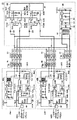
図3は、従来のセパレート形空気調和機の構成を示す回路図である。
図3を参照して、従来のセパレート形空気調和機10は、室外機11と、室内機20A,20Bと、端子板30、40、50、60および70とを備える。端子板30、40および60は、室外機11内に実装され、端子板50または70は、端子板20Aまたは20B内に実装されることもある。端子板30は室外機11に対して電源を供給するために設けられ、端子31〜33を含む。端子板40および50は、室外機11と室内機20Bとを電気的に接続するために設けられる。端子板40は端子41〜44を含み、端子板50は端子51〜54を含む。同様に、端子板60および70は、室外機11と室内機20Aとの間を電気的に接続するために設けられる。端子板60は端子61〜64を含み、端子板70は端子71〜74を含む。
【0004】
端子31、41、51、61および71はアース端子であり、これらの端子群は互いに電気的に接続されてアースへ導かれる。端子板30中の端子32および33は、外部の交流(AC)電源と接続されて、交流電源電圧を印加される。端子32はニュートラル側の電源端子に相当し、端子33はライブ側の電源端子に相当する。端子板40〜70中の端子42、52、62および72は、端子32と電気的に接続される。同様に、端子板40〜70中の端子43、53、63および73は、端子33は、電気的に接続される。
【0005】
端子64および74は、室外機11と室内機20Aとの間で信号を授受するために互いに電気的に接続される。同様に、端子44および54は、室外機11と室内機20Bとの間で信号を授受するために互いに電気的に接続されている。
【0006】
室外機11は、端子32および33に印加された外部AC電源を受けて、内部電圧V1(たとえば5V)を電源ノードNp0に生成する内部電源回路80を含む。室外機11の内部回路群は、電源ノードNp0から内部電圧V1の供給を受けて動作する。内部電源回路80は、トランス81と、整流回路82と、平滑コンデンサ83と、電源レギュレータIC84とを有する。
【0007】
室内機20Aは、室外機11から端子72および73へ供給された電源電圧を受けて、内部電圧V1(たとえば5V)を電源ノードNpAに生成する内部電源回路90Aを含む。室内機20Aの内部回路群は、電源ノードNpAから内部電圧V1の供給を受けて動作する。同様に、室内機20Bは、室外機11から端子52および53へ供給された電源電圧を受けて、内部電圧V1(たとえば5V)を電源ノードNpBに生成する内部電源回路90Bを含む。室内機20Bの内部回路群は、電源ノードNpBから内部電圧V1の供給を受けて動作する。内部電源回路90A,90Bの構成は内部電源回路80と同様である。
【0008】
このように、セパレート形空気調和機10においては、室外機11が端子板30を介して外部からAC電源の供給を受けるとともに、室内機20A,20Bへは端子板40〜70を介して室外機11から電源が供給される構成となっている。
【0009】
室外機11は、電源ノードNp0に生成された内部電圧V1を動作電圧とする室外制御部100をさらに含む。同様に、室内機20Aは、電源ノードNpAに生成された内部電圧V1を動作電圧とする室内制御部110Aをさらに含み、室内機20Bは、電源ノードNpBに生成された内部電圧V1を動作電圧とする室内制御部110Bをさらに含む。室外制御部100および室内制御部110A,110Bの各々は、たとえばマイコンによって構成される。室外制御部100は、室外機11の内部回路群の動作を制御し、室内制御部110Aおよび100Bは、室内機20Aおよび20Bの内部回路群の動作をそれぞれ制御する。
【0010】
さらに、室外制御部100と室内制御部110Aおよび110Bとの間で信号を授受するための送受信回路が設けられている。
【0011】
室外制御部100と室内制御部110A(室内機20A)との間の送受信回路は、フォトカプラFC1A,FC2A,FC3A,FC4AおよびダイオードD5,D7を含む。これに対して、室外制御部100と室内制御部110B(室内機20B)との間の送受信回路は、フォトカプラFC1B,FC2B,FC3B,FC4BおよびダイオードD6,D8を含む。フォトカプラFC1A,FC2A,FC1B,FC2BおよびダイオードD5,D6は室外機11内に設けられる。フォトカプラFC3A,FC4AおよびダイオードD7は室内機20Aに設けられ、フォトカプラFC3B,FC4BおよびダイオードD8は室内機20Bに設けられる。
【0012】
さらに、室外制御部100と室内制御部110Aとの間の送受信回路の電源を供給するための内部電源回路120Aが室内機20A内に設けられている。内部電源回路120Aは、室外機11から端子72および73に供給された電源電圧を受けて、端子72(ニュートラル端子)を基準とする負電圧V2(たとえば−24V)をノードNsAに生成する。
【0013】
同様に、室外制御部100と室内制御部110Bとの間の送受信回路へ電源を供給するための内部電源回路120Bは、室内機20B内に設けられている。内部電源回路120Bは、室外機11から端子52および53に供給された電源電圧を受けて、ノードNsBに端子52(ニュートラル端子)を基準とする負電圧V2(たとえば−24V)を生成する。
【0014】
フォトカプラFC1A〜FC4A,FC1B〜FC4Bの各々は、フォトトランジスタとフォトダイオードとの組で構成されている。各フォトカプラにおいて、フォトダイオードの電流通過(通電)に応答したフォトトランジスタがターンオンする。たとえば、フォトカプラFC1AはフォトダイオードD1AおよびフォトトランジスタT1Aで構成され、フォトダイオードD1Aの電流通過時にフォトトランジスタT1Aがターンオンする。その他のフォトカプラFC2A〜FC4A,FC1B〜FC4Bは、フォトダイオードD2A〜D4A,D1B〜D4BおよびフォトトランジスタT2A〜T4A,T1B〜T4Bをそれぞれ有する。
【0015】
これによって、室内機側と室外機側とを電気的に絶縁した状態で、両者の間で信号の授受を実行することができる。このような送受信回路によって、室外制御部100と室内制御部110Aおよび110Bとの間で、シリアルなパルス信号列を送受信することができる。たとえば、ワイヤレスリモコン140Aおよび140Bからそれぞれ入力されたユーザ要求を、室内制御部110Aおよび110Bによって所定のパルス信号列に変換し、当該パルス信号列を上記の送受信回路を介して、室外制御部100へ伝送することができる。反対に、室外制御部100からは室内機20Aおよび20Bの動作を制御するための所定のパルス信号列を、室内制御部110A,110Bへ伝送することができる。
【0016】
図3に示した従来のセパレート形空気調和機10の構成では、室内機20Aおよび20Bの各々では、非運転時において、内部電源回路90A,90B,120A,120Bによる室内制御部110A,110Bおよび送受信回路への電源供給が継続された状態で、ワイヤレスリモコン140A,140Bに対する運転要求等の指示入力を待つことなる。
【0017】
したがって、室外機11に外部から電源が供給されている間では、室内機20Aおよび20Bの両方が非運転状態となる待機動作時においても、室外制御部100および室内制御部110A,110Bが動作しているため、電力が消費され無駄な電気代が必要となる。
【0018】
待機動作時における消費電力を低減するための構成としては、これまでに、たとえば待機中に室外機内のマイコン(室外制御部)への電源供給を遮断して待機電力を制御するセパレート形空気調和機(たとえば特許文献1を参照)や、待機状態における室外制御部への動作電力の供給を停止して省電力化を図るとともに、室外機のみの単独運転を可能とするセパレート形空気調和機(たとえば特許文献2を参照)が提案されている。
【0019】
【特許文献1】
特開2000−111123号公報(第1頁)
【0020】
【特許文献2】
特開2001−12782号公報(第1頁)
【0021】
【発明が解決しようとする課題】
しかしながら、セパレート形空気調和機においては、1台の室外機に対して、多数の室内機が接続される構成が一般的である。したがって、待機動作時に室外機側への電源供給を遮断したとしても、室内機側での電力消費が低減されなければ、空気調和機全体としての消費電力の削減は効果が小さくなる。
【0022】
また、同一の室外機に接続された多数の室内機のうち、すべてが運転状態とされることは少なく、1台もしくは2台を運転するケースが多いと考えられる。したがって、すべての室内機が非運転状態となる待機動作時のみならず、一部の室内機が運転状態である通常運転時にも、残りの非運転状態である室内機における電力消費を低減することが、空気調和機全体としての低消費電力化において重要である。
【0023】
したがって、上述の特許文献1および特許文献2では、待機状態時における室内機側に対する電源供給が考慮されていないため、空気調和機全体としての低消費電力効果はそれほど大きくならないものと考えられる。
【0024】
この発明は、このような問題点を解決するためになされたものであって、この発明の目的は、セパレート形空気調和機の消費電力を削減することである。
【0025】
【課題を解決するための手段】
この発明に従う空気調和機は、外部から電源の供給を受ける室外機と、 室外機から電源の供給を受けて動作する複数の室内機とを備える。室外機は、複数の室内機にそれぞれ対応して設けられ、各々が室外機から対応する室内機への電源の供給を制御するためにオンまたはオフされる複数の電源供給スイッチと、外部から供給された電源によって動作して、複数の電源供給スイッチのオンおよびオフを制御する室外制御部とを含み、室外制御部は、複数の電源供給スイッチのそれぞれに対して、対応する室内機の非運転時には所定期間ターンオフを指示する。
【0026】
好ましくは、室外制御部は、複数の電源供給スイッチのそれぞれに対して、対応する室内機の非運転時にはターンオフおよびターンオンを交互に指示する。
【0027】
また好ましくは、複数の室内機の各々は、自身の動作を制御するための室内制御部を含み、空気調和機は、複数の室内機にそれぞれ含まれる室内制御部と室外制御部との間で信号をそれぞれ授受するための複数の送受信回路をさらに備える。室外機は、外部から供給された電源を受けて、複数の送受信回路の動作電圧を生成する内部電源回路をさらに含む。
【0028】
さらに好ましくは、複数の送受信回路の各々は、室外機に設けられた第1の光結合素子と、対応する室内機に設けられた第2の光結合素子とを含む。
【0029】
あるいは好ましくは、複数の室内機の各々は、自身の動作を制御するための室内制御部と、室内制御部へ所定の動作電圧を供給するための電荷供給部と、対応する電源供給スイッチのターンオン時に、電荷供給部を所定の動作電圧に充電する充電回路とを含む。
【0030】
さらに好ましくは、電荷供給部は、電気二重層コンデンサで構成される。
あるいは好ましくは、室外制御部は、非運転状態であった室内機に対して運転要求が発せられた場合に、対応する電源供給スイッチにターンオンを指示する。
【0031】
さらに好ましくは、複数の室内機の各々は、自身の動作を制御するための室内制御部を含み、空気調和機は、複数の室内機にそれぞれ含まれる室内制御部と室外制御部との間で信号をそれぞれ授受するための複数の送受信回路をさらに備え、複数の送受信回路の各々は、対応する室内制御部へ入力された運転要求を室外制御部へ伝送し、室外制御部は、伝送された運転要求に応答して、対応する電源供給スイッチにターンオンを指示する。
【0032】
特にこのような構成においては、複数の室内機の各々は、運転要求の入力を検知するための受信回路と、受信回路および室内制御部へ所定電圧を動作電圧として供給するための電荷供給部と、対応する電源供給スイッチのターンオン時に、電荷供給部を所定電圧に充電する充電回路とを含む。
【0033】
あるいは、このような構成においては、室外機は、外部から供給された電源を受けて、複数の送受信回路の動作電圧を生成する内部電源回路をさらに含む。
【0034】
また好ましくは、室外制御部は、空気調和機の待機動作時において、複数の電源供給スイッチの各々に対して所定期間ターンオフを指示する。
【0035】
【発明の実施の形態】
以下において、本発明の実施の形態について図面を参照して詳細に説明する。
【0036】
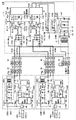
図1は、本発明の実施の形態に従うセパレート形空気調和機10♯の構成を示す回路図である。
【0037】
図1を参照して、実施の形態に従うセパレート形空気調和機10♯は、図3に示した従来のセパレート形空気調和機10と同様に、室外機11と、室内機20A,20Bと、端子板30,40,50,60,70とを備える。端子板30〜70の配置および接続関係と、端子板30中の端子32および33に外部からAC電源が接続される点については、従来のセパレート形空気調和機10と同様であるので詳細な説明は繰返さない。
【0038】
なお、図1においては、1つの室外機に対して2つの室内機20A,20Bが接続される構成を示しているが、同様の構成は、任意の複数個の室外機を備えたセパレート形構成の空気調和機に適用できる。
【0039】
本発明に従うセパレート形空気調和機における室内機20Aおよび20Bの構成について、まず説明する。室内機20Aおよび20Bは、図3での構成と比較して、それぞれの内部回路群に内部電圧V1を供給するための電荷供給部220Aおよび220Bをさらに含む。室内制御部110Aおよびワイヤレスリモコンの受信回路130Aは、電荷供給部220Aから動作電圧(内部電圧V1)の供給を受け、室内制御部110Bおよびワイヤレスリモコンの受信回路130Bは、電荷供給部220Bから動作電源(内部電圧V1)の供給を受ける。
【0040】
電荷供給部220Aは、室外機11から室内機20Aへの電源供給期間において、内部電源回路90Aによって内部電圧V1に充電される。室外機11から室内機20Aへの電源供給が遮断された場合にも、電荷供給部220Aによって、室内制御部110Aおよびワイヤレスリモコンの受信回路130A等の内部回路へ動作電源が供給される。同様に、電荷供給部220Bは、室外機11から室内機20Bへ電源供給期間において、内部電源回路90Bによって内部電圧V1に充電される。室外機11から室内機20Bへの電源供給が遮断された場合にも、電荷供給部220Bによって、室内制御部110Bおよびワイヤレスリモコンの受信回路130B等の内部回路へ動作電源が供給される。
【0041】
電荷供給部220A,220Bとしては、電気二重層コンデンサが好適である。あるいは、充電可能な二次電池を電荷供給部220A,220Bとして用いることもできる。電気二重層コンデンサは、アルミ電解コンデンサ等の一般のコンデンサと比較して大きな容量を得ることができるため、その電荷供給能力が高いことが特徴である。アルミ電解コンデンサの使用は、使用可能温度範囲が広い点、二次電池の適用時に必要となる充放電の制御回路が不要となる点、比較的急速な充電が可能である点および、数十万回以上の充放電が可能であり長期間の運転にも耐えられるという点で有利である。
【0042】
さらに、室外制御部100と室内制御部110A,110Bの間の送受信回路に対して動作電圧V2を供給するための内部電源回路120Aおよび120Bは、室内機20A,20B内ではなく、室外機11内に設けられる。室内機20Aおよび20Bに関するその他の部分の構成は、図3に示したと同様であるので詳細な説明は繰返さない。
【0043】
次に、本発明に従うセパレート形空気調和機における室外機の構成について説明する。
【0044】
室外機11は、図3に示した構成と比較して、電源スイッチ200A,200Bと、電源スイッチ制御回路210A,210Bとをさらに含む点で異なる。さらに、既に述べたように、従来のセパレート形空気調和機10では室内機20Aおよび20Bに配置されていた内部電源回路120A,120Bが、室外機11の内部に設けられている。
【0045】
電源スイッチ200Aは、室外機11から室内機20Aへの電源供給を制御するために端子33と端子63との間に設けられ、電源スイッチ200Bは、室外機11から室内機20Bへの電源供給を制御するために端子33と端子43との間に設けられる。電源スイッチ200Aおよび200Bは、リレースイッチや、SSR(Solid State Relay)等の半導体スイッチで構成される。
【0046】
電源スイッチ制御回路210Aは、インバータ(トランジスタ)211Aと、ダイオード212Aと、リレーコイル215Aとを含む。電源スイッチ200Aは、リレーコイル215Aの通電時にオンし、それ以外ではオフする。同様に、電源スイッチ制御回路210Bは、インバータ(トランジスタ)211Bと、ダイオード212Bと、リレーコイル215Bとを含む。電源スイッチ200Bは、リレーコイル215Bの通電時にオンし、それ以外ではオフする。
【0047】
ダイオード212Aは、インバータ(トランジスタ)211Aの出力ノードから内部電圧V3へ向かう方向を順方向とするように接続される。内部電圧V3は、たとえば、室外機11に設けられた図示しない内部電源回路によって生成される。ノードNcAおよびNcBの電圧レベルは、室外制御部100によって、Lレベル(0V)およびHレベル(5V)のいずれかに設定される。電源スイッチ制御回路210Aにおいて、インバータ(トランジスタ)211Aは、ノードNcAの電圧レベル(Lレベル/Hレベル)を反転して、その出力ノードをHレベル(12V)およびLレベル(0V)のいずれかに設定する。ダイオード212Aおよびリレーコイル215Aは、内部電圧V3(たとえば12V)およびインバータ(トランジスタ)211Aの出力ノードの間に並列接続される。
【0048】
室外制御部100がノードNcAをHレベルに設定すると、インバータ(トランジスタ)211Aの出力がLレベル(0V)となるので、リレーコイル215Aが通電しこれに応答して電源スイッチ200Aがターンオンする。これに対して、ノードNcAをLレベルに設定すると、インバータ(トランジスタ)211Aの出力がHレベル(12V)となることからリレーコイル215Aには電流が流れず、電源スイッチ200Aはオフされる。
【0049】
電流スイッチ制御回路210Bの構成および電流スイッチ200Bのオン・オフ制御についても、同様であるので詳細な説明は繰返さない。この結果、室外制御部100によるノードNcA,NcBの電圧設定に応じて、電源スイッチ200Aおよび200Bのオン・オフを制御して、室外機11から室内機20Aおよび20Bのそれぞれへの電源供給を制御することができる。
【0050】
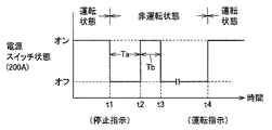
図2は、図1に示された電源スイッチのオン・オフ制御を説明する概念図である。
【0051】
図2では、電源スイッチ200Aによる室内機20Aへの電源供給制御について、代表的に説明する。図2を参照して、運転状態であった室内機20Aに対して、時刻t1に停止指示が発せられ、その後の時刻t4において、再び運転指示が発せられるものとする。
【0052】
時刻t1以前では、室内機20Aが運転状態であるので電源スイッチ200Aはオンされており、室外機11から室内機20Aへ電源が供給されている。時刻t1において、対応する室内機20Aが非運転状態となると、これに応答して電源スイッチ200Aはオフされて、室外機11から室内機20Aへの電源供給が遮断される。
【0053】
既に説明したように、電源スイッチ200Aのオフ期間においても、図1に示した電荷供給部220Aによって、対応する室内機の内部回路群(室内制御部110Aおよび受信回路130A等)は動作可能な状態に維持される。しかしながら、時刻t1以降において、電荷供給部220Aによって供給される動作電圧は、内部回路群での電力消費に応じて、徐々に低下する。
【0054】
したがって、電源スイッチ200Aのターンオフ(時刻t1)から所定時間Ta経過後の時刻t2において、電荷供給部220Aを充電して動作電圧レベルを復帰させるために、電源スイッチ200Aは再びターンオンされる。さらに、時刻t2から所定時間Tb経過後の時刻t3において、電源スイッチ200Aは、消費電力を削減するために再びターンオフされる。所定時間Taは、非運転状態の室内機20Aにおける内部回路群の消費電力および電荷供給部220Aの電荷供給力(コンデンサ容量)を考慮して、電荷供給部220Aによる供給電圧の電圧降下が許容範囲を超えてしまうまでの時間に対応させて予め設定される。同様に、所定時間Tbは、内部電源回路90Aの充電能力および電荷供給部220Aの電荷蓄積力(コンデンサ容量)を考慮して、電荷供給部220Aによる供給電圧が所定電圧に復帰するのに必要な時間に対応させて予め設定される。
【0055】
所定時間Ta,Tbの経過は、たとえば、室外制御部100,室内制御部110A,110Bを構成するマイコンのタイマ機能を用いて検知可能である。すなわち、室内制御部110A,110B側において所定時間Ta,Tbの経過を検知して、送受信回路を介して室外制御部100に電源スイッチ200A,200Bのオンまたはオフを要求する構成としてもよいし、室外制御部100側のみで電源スイッチ200A,200Bのオン・オフを制御する構成としてもよい。
【0056】
なお、原理的には、室内機20Aにおいて、内部電圧V1の電圧降下を直接的に検知して、室内制御部110A,110Bから室外制御部100へ電源スイッチ200Aのターンオン要求を発することも可能ではある。しかしながら、上述したように、所定時間の経過によって動作電圧の降下を予測的に検知する構成とすることによって、電圧降下を検出する専用回路を設ける必要がなくなるので、回路構成を簡素化できる。
【0057】
以降、同様のオンおよびオフ動作が、対応する室内機が運転状態に復帰する時刻t4まで交互に繰り返される。時刻t4以降の運転状態時には、電源スイッチ200Aがオンして、室外機11から室内機20Aへ電源が常時供給される。
【0058】
電源スイッチ200Bのオン・オフも、室内機20Bの運転状態および非運転状態に応じて、電源スイッチ200Aと同様に制御される。すなわち、電源スイッチ200Aおよび200Bは、室内機20Aおよび20Bにそれぞれ対応して、独立に制御される。その結果、全ての室内機20A,20Bが非運転状態となる待機動作時には、各電源スイッチ200A、200Bはオフされる。
【0059】
以上の説明から理解されるように、セパレート形空気調和機においては、運転状態時および非運転状態の各々において、室外機11と室内機20A,20Bとの間で、送受信回路によるパルス信号列の伝送が確保される必要がある。以下においては、本発明の実施の形態に従うセパレート形空気調和機10における、送受信回路の構成および動作について説明する。
【0060】
室外機11および室内機20Aの間で信号を授受するために送受信回路を構成する、フォトカプラFC1A〜FC4AおよびダイオードD5,D7は、以下のように接続される。
【0061】
室外機11において、フォトトランジスタT1Aは、電源ノードNp0およびノードN1Aの間に接続され、フォトダイオードD2Aは、電源ノードNp0およびノードN2Aの間に接続される。さらに、ダイオードD5、フォトダイオードD1AおよびフォトトランジスタT2Aは、端子64およびノードNsA♯の間に直列に接続される。また、室内機20Aにおいて、ダイオードD7、フォトダイオードD3AおよびフォトトランジスタT4Aは端子72および端子74の間に直列に接続される。さらに、フォトトランジスタT3AおよびフォトダイオードD4Aは、電源ノードNpAとノードN3AおよびN4Aとの間にそれぞれ接続されている。
【0062】
なお、本実施の形態において、フォトカプラは光結合素子の代表例として示されるものとする。
【0063】
内部電源回路120Aは、図1に示したのと同様の構成を有し、端子62(ニュートラル端子)を基準とする負電圧V2をノードNsA♯に生成する。同様に、内部電源回路120Bは、端子42(ニュートラル端子)を基準とする負電圧V2をノードNsB♯に生成する。
【0064】
次に、室外制御部100および室内制御部110Aの間の送受信回路の動作について代表的に説明する。
【0065】
送受信回路においては、室内機側から室外機側へ信号を伝送する第1のモードと、室外機側から室内機側へ信号を伝送するための第2のモードとが交互に周期的に設定されている。
【0066】
上記第1のモードにおいては、受信側の室外制御部100は、ノードN2Aの電圧をLレベル(0V)に固定して、フォトダイオードD2Aを通電させる。これにより、フォトトランジスタT2Aがオンする。この結果、第1のモードでは、端子72−ダイオードD7−フォトダイオードD3A−フォトトランジスタT4A−端子74−端子64−ダイオードD5−フォトダイオードD1A−フォトトランジスタT2A−ノードNsA♯の経路(以下、「信号伝達経路」と称する)に電流が流れるか否かは、室内機20A側のフォトトランジスタT4Aがオンするか否かに依存することになる。
【0067】
送信側の室内制御部110Aは、Hレベル信号の送信期間においては、ノードN4AをLレベル(0V)に設定してフォトダイオードD4Aを導通させることにより、上記信号伝達経路に電流を流す。一方、Lレベル信号の送信期間においては、ノードN4AがHレベル(5V)に設定されてフォトダイオードD4Aは非導通とされ、上記信号伝達経路に電流は流れない。
【0068】
信号伝達経路に電流が流れると、室外機11において、フォトダイオードD1Aの導通に応答してフォトトランジスタT1Aがオンするので、ノードN1AはHレベル(5V)に設定される。反対に、信号伝達経路に電流が流れないとフォトトランジスタT1Aはオフするので、ノードN1AはLレベル(0V)に設定される。すなわち、受信側の室外制御部100は、ノードN1Aの電圧レベルに応じて、室内制御部110Aが設定したノードN4Aの電圧レベルを検知できる。この結果、ノードN4Aの電圧レベル(Hレベル/Lレベル)遷移に相当するパルス信号が、室内制御部110Aから室外制御部100へ伝送される。
【0069】
反対に、室外機側から室内機側へ信号を伝送するための第2のモードにおいては、受信側の室内制御部110Aは、ノードN4AをLレベル(0V)に固定して、フォトトランジスタT4Aをオンさせる。この結果、信号伝達経路に電流が流れる否かは、室外機11側のフォトトランジスタT2Aがオンするか否か、すなわち室外制御部100に設定されたノードN2Aの電圧レベルに依存することになる。したがって、受信側の室内制御部110Aは、ノードN3Aの電圧レベルに応じて、室内制御部110Aが設定したノードN2Aの電圧レベルを検知できる。この結果、ノードN2Aの電圧レベル(Hレベル/Lレベル)遷移に相当するパルス信号が、室外制御部100から室内制御部110Aへ伝送される。
【0070】
フォトカプラFC1B〜FC4BおよびダイオードD6およびD8によって構成される、室外機11および室内機20Bの間の送受信回路についても、上述した室外機11および室内機20Aの間の送受信回路と同様に構成される。また、室外機11および室内機20Bとの間におけるパルス信号の伝送についても同様に実行されるので詳細な説明は繰返さない。
【0071】
これらの送受信回路に電源を供給する内部電源回路120A,120Bを室外機に設けることにより、対応する電源スイッチがオフされて室内機側への電源供給が遮断された期間にも、非運転状態の室内機と室外機との間で、パルス信号の授受による情報伝達が可能となる。
【0072】
これにより、特に、非運転状態の室内機を再び運転状態とする要求がワイヤレスリモコン140A,140Bへ入力された場合に、当該要求を室外制御部100に伝送し、対応する電源スイッチをターンオンして、室内機への電源供給を再開する経路を確保できる。
【0073】
以上説明したように、本発明の実施の形態に従うセパレート形空気調和機においては、非運転状態の室内機に対する室外機からの電源供給を遮断するため、非運転状態の室内機における消費電力が削減できる。さらに、非運転状態の室内機においても、内部回路への動作電源の供給および室内機との間の情報伝達が正常に実行されるので、非運転状態の室内機をスムーズに運転状態へ復帰させることができる。
【0074】
したがって、すべての室内機が非運転状態となる待機動作時において、複数の室内機の各々における電力消費を削減できるので、空気調和機全体の消費電力を効果的に低減することができる。また、一部の室内機が運転状態である場合にも、残りの非運転状態の室内機の消費電力を削減できるので、空気調和機全体の消費電力を有効に低減することができる。
【0075】
今回開示された実施の形態はすべての点で例示であって制限的なものではないと考えられるべきである。本発明の範囲は上記した説明ではなくて特許請求の範囲によって示され、特許請求の範囲と均等の意味および範囲内でのすべての変更が含まれることが意図される。
【0076】
【発明の効果】
この発明は、以上説明したように、外部から電源を供給される室外機と、室外機から電源を供給される複数の室内機とを備えたセパレート形空気調和機において、非運転状態の室内機に対する室外機からの電源供給を遮断するため、空気調和機全体の消費電力を有効に低減することができる。
【0077】
さらに、室外機と室内機との間で信号を授受する送受信回路の電源回路を室外機側に設けるので、非運転状態の室内機においても、室内機との間の情報伝達が正常に実行される。この結果、非運転状態の室内機をスムーズに運転状態へ復帰させることができる。
【0078】
また、非運転状態の室内機において、所定時間の経過に応じて電源スイッチをオフまたはオンさせるので、室内機側に電圧降下を検知する専用回路を設けることなく、内部回路への動作電源の供給が正常に実行される。したがって、非運転状態の室内機をスムーズに運転状態へ復帰させることができる。
【図面の簡単な説明】
【図1】本発明の実施の形態に従うセパレート形空気調和機の構成を示す回路図である。
【図2】図1に示された電源スイッチのオン・オフ制御を説明する概念図である。
【図3】従来のセパレート形空気調和機の構成を示す回路図である。
【符号の説明】
10,10♯ セパレート形空気調和機、11 室外機、20A,20B 室内機、30,40,50,60,70 端子板、80,90A,90B 内部電源回路(内部回路用)、100 室外制御部(マイコン)、110A,110B室内制御部(マイコン)、120A,120B 内部電源回路(送受信回路用)、140A,140B ワイヤレスリモコン、200A,200B 電源スイッチ、210A,210B 電源スイッチ制御回路、215A,215B リレーコイル、220A,220B 電荷供給部(電気二重層コンデンサ)、FC1A〜FC4A,FC1B〜FC4B フォトカプラ(光結合素子)、Ta,Tb所定時間、V1〜V3 内部電圧。[0001]
TECHNICAL FIELD OF THE INVENTION
The present invention relates to an air conditioner, and more particularly, to a separate type air conditioner including an outdoor unit and an indoor unit.
[0002]
[Prior art]
Generally, in a separate type air conditioner including an outdoor unit and an indoor unit, one of the indoor unit and the outdoor unit is connected to an external commercial alternating current (AC) power supply.
[0003]
FIG. 3 is a circuit diagram showing a configuration of a conventional separate type air conditioner.
Referring to FIG. 3, a conventional separate
[0004]
The
[0005]
The
[0006]
[0007]
[0008]
As described above, in the separate
[0009]
[0010]
Further, a transmission / reception circuit for exchanging signals between the
[0011]
The transmission / reception circuit between the
[0012]
Further, an internal
[0013]
Similarly, an internal power supply circuit 120B for supplying power to a transmission / reception circuit between the
[0014]
Each of the photocouplers FC1A to FC4A and FC1B to FC4B is constituted by a set of a phototransistor and a photodiode. In each photocoupler, the phototransistor in response to the current passing (energization) of the photodiode is turned on. For example, the photocoupler FC1A includes the photodiode D1A and the phototransistor T1A, and the phototransistor T1A turns on when the current of the photodiode D1A passes. The other photocouplers FC2A to FC4A, FC1B to FC4B have photodiodes D2A to D4A, D1B to D4B and phototransistors T2A to T4A, T1B to T4B, respectively.
[0015]
Thus, signals can be transmitted and received between the indoor unit and the outdoor unit while the two are electrically insulated from each other. With such a transmission and reception circuit, a serial pulse signal train can be transmitted and received between the
[0016]
In the configuration of the conventional separate
[0017]
Therefore, while power is supplied to the
[0018]
As a configuration for reducing power consumption during standby operation, a separate air conditioner that controls standby power by interrupting power supply to a microcomputer (outdoor control unit) in an outdoor unit during standby, for example, has been proposed. (See, for example, Patent Literature 1) and a separate type air conditioner (for example, which stops power supply to the outdoor control unit in a standby state to save power and enables independent operation of the outdoor unit alone) Patent Document 2) has been proposed.
[0019]
[Patent Document 1]
JP-A-2000-111123 (page 1)
[0020]
[Patent Document 2]
JP 2001-12782 A (page 1)
[0021]
[Problems to be solved by the invention]
However, in a separate type air conditioner, a configuration in which many indoor units are connected to one outdoor unit is general. Therefore, even if the power supply to the outdoor unit is cut off during the standby operation, if the power consumption on the indoor unit side is not reduced, the effect of reducing the power consumption of the air conditioner as a whole is reduced.
[0022]
In addition, among many indoor units connected to the same outdoor unit, it is considered that all of the indoor units are rarely brought into an operation state, and one or two units are often operated. Therefore, not only during the standby operation when all the indoor units are in the non-operation state, but also during the normal operation in which some of the indoor units are in the operation state, the power consumption of the remaining indoor units in the non-operation state should be reduced. However, it is important in reducing the power consumption of the air conditioner as a whole.
[0023]
Therefore, in Patent Literature 1 and
[0024]
The present invention has been made to solve such a problem, and an object of the present invention is to reduce the power consumption of a separate type air conditioner.
[0025]
[Means for Solving the Problems]
An air conditioner according to the present invention includes an outdoor unit that receives power supply from outside, and a plurality of indoor units that operate by receiving power supply from the outdoor unit. An outdoor unit is provided corresponding to each of the plurality of indoor units, a plurality of power supply switches that are turned on or off to control the supply of power from the outdoor unit to the corresponding indoor unit, and a plurality of power supply switches supplied from outside. An outdoor control unit that is operated by the supplied power supply and controls on and off of the plurality of power supply switches, wherein the outdoor control unit performs a non-operation of the corresponding indoor unit for each of the plurality of power supply switches. Sometimes, a turn-off instruction is given for a predetermined period.
[0026]
Preferably, the outdoor control unit instructs each of the plurality of power supply switches to turn off and turn on alternately when the corresponding indoor unit is not operating.
[0027]
Also preferably, each of the plurality of indoor units includes an indoor control unit for controlling its own operation, and the air conditioner includes an indoor control unit and an outdoor control unit included in each of the plurality of indoor units. It further includes a plurality of transmission / reception circuits for transmitting and receiving signals. The outdoor unit further includes an internal power supply circuit that receives power supplied from the outside and generates operating voltages of the plurality of transmission / reception circuits.
[0028]
More preferably, each of the plurality of transmission / reception circuits includes a first optical coupling element provided in an outdoor unit and a second optical coupling element provided in a corresponding indoor unit.
[0029]
Alternatively, preferably, each of the plurality of indoor units has an indoor control unit for controlling its own operation, a charge supply unit for supplying a predetermined operation voltage to the indoor control unit, and a corresponding power supply switch turned on. A charging circuit for charging the charge supply unit to a predetermined operating voltage.
[0030]
More preferably, the charge supply unit is configured by an electric double layer capacitor.
Alternatively, preferably, when an operation request is issued to the indoor unit that has been in the non-operation state, the outdoor control unit instructs the corresponding power supply switch to turn on.
[0031]
More preferably, each of the plurality of indoor units includes an indoor control unit for controlling its own operation, and the air conditioner includes an indoor control unit and an outdoor control unit included in each of the plurality of indoor units. A plurality of transmission / reception circuits for transmitting and receiving signals are further provided, and each of the plurality of transmission / reception circuits transmits an operation request input to a corresponding indoor control unit to an outdoor control unit, and the outdoor control unit transmits the transmitted request. In response to the operation request, the corresponding power supply switch is instructed to turn on.
[0032]
In particular, in such a configuration, each of the plurality of indoor units has a receiving circuit for detecting an input of an operation request, and a charge supply unit for supplying a predetermined voltage to the receiving circuit and the indoor control unit as an operating voltage. And a charging circuit for charging the charge supply unit to a predetermined voltage when the corresponding power supply switch is turned on.
[0033]
Alternatively, in such a configuration, the outdoor unit further includes an internal power supply circuit that receives power supplied from the outside and generates operating voltages of the plurality of transmission / reception circuits.
[0034]
Preferably, the outdoor control unit instructs each of the plurality of power supply switches to turn off for a predetermined period during a standby operation of the air conditioner.
[0035]
BEST MODE FOR CARRYING OUT THE INVENTION
Hereinafter, embodiments of the present invention will be described in detail with reference to the drawings.
[0036]
FIG. 1 is a circuit diagram showing a configuration of a separate
[0037]
Referring to FIG. 1, a separate
[0038]
Although FIG. 1 shows a configuration in which two
[0039]
First, the configuration of the
[0040]
The
[0041]
As the
[0042]
Further, the internal
[0043]
Next, the configuration of the outdoor unit in the separate type air conditioner according to the present invention will be described.
[0044]
The
[0045]
The
[0046]
The power
[0047]
[0048]
When the
[0049]
The same applies to the configuration of current switch control circuit 210B and the on / off control of current switch 200B, and therefore detailed description will not be repeated. As a result, according to the voltage setting of the nodes NcA and NcB by the
[0050]
FIG. 2 is a conceptual diagram illustrating on / off control of the power switch shown in FIG.
[0051]
In FIG. 2, control of power supply to
[0052]
Before time t1, since the
[0053]
As already described, even during the OFF period of the
[0054]
Therefore, at time t2 after elapse of the predetermined time Ta from turn-off of
[0055]
The lapse of the predetermined times Ta and Tb can be detected using, for example, a timer function of a microcomputer included in the
[0056]
In principle, in the
[0057]
Thereafter, the similar ON and OFF operations are alternately repeated until time t4 when the corresponding indoor unit returns to the operating state. In an operation state after time t4, the
[0058]
ON / OFF of the power switch 200B is controlled in the same manner as the
[0059]
As can be understood from the above description, in the separate type air conditioner, the pulse signal train by the transmission / reception circuit between the
[0060]
The photocouplers FC1A to FC4A and the diodes D5 and D7, which constitute a transmitting and receiving circuit for exchanging signals between the
[0061]
In
[0062]
In this embodiment, a photocoupler is shown as a typical example of an optical coupling element.
[0063]
Internal
[0064]
Next, the operation of the transmission / reception circuit between the
[0065]
In the transmitting / receiving circuit, a first mode for transmitting a signal from the indoor unit to the outdoor unit and a second mode for transmitting a signal from the outdoor unit to the indoor unit are alternately and periodically set. ing.
[0066]
In the first mode, the
[0067]
During the transmission period of the H level signal, the
[0068]
When a current flows through the signal transmission path, in the
[0069]
Conversely, in the second mode for transmitting a signal from the outdoor unit to the indoor unit, the reception-side
[0070]
The transmission / reception circuit between the
[0071]
By providing the internal
[0072]
Thereby, in particular, when a request to set the indoor unit in the non-operation state to the operation state again is input to the wireless
[0073]
As described above, in the separate type air conditioner according to the embodiment of the present invention, since the power supply from the outdoor unit to the non-operational indoor unit is cut off, the power consumption in the non-operational indoor unit is reduced. it can. Furthermore, even in the non-operating state indoor unit, the supply of the operating power to the internal circuit and the information transmission between the indoor unit are performed normally, so that the non-operating state indoor unit is smoothly returned to the operating state. be able to.
[0074]
Therefore, during the standby operation in which all the indoor units are in the non-operation state, the power consumption of each of the plurality of indoor units can be reduced, so that the power consumption of the entire air conditioner can be effectively reduced. Further, even when some of the indoor units are in the operating state, the power consumption of the remaining indoor units in the non-operating state can be reduced, so that the power consumption of the entire air conditioner can be effectively reduced.
[0075]
The embodiments disclosed this time are to be considered in all respects as illustrative and not restrictive. The scope of the present invention is defined by the terms of the claims, rather than the description above, and is intended to include any modifications within the scope and meaning equivalent to the terms of the claims.
[0076]
【The invention's effect】
As described above, the present invention relates to a non-operating indoor unit in a separate type air conditioner including an outdoor unit supplied with power from the outside and a plurality of indoor units supplied with power from the outdoor unit. The power supply from the outdoor unit to the air conditioner is cut off, so that the power consumption of the entire air conditioner can be effectively reduced.
[0077]
Furthermore, since the power supply circuit of the transmission / reception circuit for transmitting and receiving signals between the outdoor unit and the indoor unit is provided on the outdoor unit side, even in the non-operation state indoor unit, information transmission with the indoor unit is executed normally. You. As a result, the indoor unit in the non-operation state can be smoothly returned to the operation state.
[0078]
In addition, in the non-operating state indoor unit, the power switch is turned off or on according to the elapse of a predetermined time, so that the operation power supply to the internal circuit can be performed without providing a dedicated circuit for detecting a voltage drop on the indoor unit side. Is executed normally. Therefore, the indoor unit in the non-operation state can be smoothly returned to the operation state.
[Brief description of the drawings]
FIG. 1 is a circuit diagram showing a configuration of a separate type air conditioner according to an embodiment of the present invention.
FIG. 2 is a conceptual diagram illustrating on / off control of a power switch shown in FIG.
FIG. 3 is a circuit diagram showing a configuration of a conventional separate type air conditioner.
[Explanation of symbols]
10, 10♯ Separate type air conditioner, 11 outdoor unit, 20A, 20B indoor unit, 30, 40, 50, 60, 70 terminal board, 80, 90A, 90B internal power supply circuit (for internal circuit), 100 outdoor control unit (Microcomputer), 110A, 110B indoor control unit (microcomputer), 120A, 120B internal power supply circuit (for transmission / reception circuit), 140A, 140B wireless remote control, 200A, 200B power switch, 210A, 210B power switch control circuit, 215A, 215B relay Coil, 220A, 220B Charge supply section (electric double layer capacitor), FC1A to FC4A, FC1B to FC4B Photocoupler (optical coupling element), Ta, Tb predetermined time, V1 to V3 internal voltage.
Claims (11)
前記室外機から前記電源の供給を受けて動作する複数の室内機とを備え、
前記室外機は、
前記複数の室内機にそれぞれ対応して設けられ、各々が前記室外機から対応する室内機への前記電源の供給を制御するためにオンまたはオフされる複数の電源供給スイッチと、
前記外部から供給された電源によって動作して、前記複数の電源供給スイッチのオンおよびオフを制御する室外制御部とを含み、
前記室外制御部は、前記複数の電源供給スイッチのそれぞれに対して、対応する前記室内機の非運転時には所定期間ターンオフを指示する、空気調和機。An outdoor unit that receives power from the outside,
A plurality of indoor units that operate by receiving the power supply from the outdoor unit,
The outdoor unit is
A plurality of power supply switches provided respectively corresponding to the plurality of indoor units, each of which is turned on or off to control supply of the power from the outdoor unit to the corresponding indoor unit,
An outdoor controller that operates on the power supplied from the outside and controls on and off of the plurality of power supply switches,
The air conditioner, wherein the outdoor control unit instructs each of the plurality of power supply switches to turn off for a predetermined period when the corresponding indoor unit is not operating.
前記空気調和機は、前記複数の室内機にそれぞれ含まれる前記室内制御部と前記室外制御部との間で信号をそれぞれ授受するための複数の送受信回路をさらに備え、
前記室外機は、前記外部から供給された電源を受けて、前記複数の送受信回路の動作電圧を生成する内部電源回路をさらに含む、請求項1または請求項2記載の空気調和機。Each of the plurality of indoor units includes an indoor control unit for controlling its own operation,
The air conditioner further includes a plurality of transmission and reception circuits for transmitting and receiving signals between the indoor control unit and the outdoor control unit included in the plurality of indoor units, respectively.
The air conditioner according to claim 1, wherein the outdoor unit further includes an internal power supply circuit that receives power supplied from the outside and generates operating voltages of the plurality of transmission / reception circuits.
自身の動作を制御するための室内制御部と、
前記室内制御部へ所定の動作電圧を供給するための電荷供給部と、
対応する前記電源供給スイッチのターンオン時に、前記電荷供給部を前記所定の動作電圧に充電する充電回路とを含む、請求項1〜4のいずれか1項に記載の空気調和機。Each of the plurality of indoor units,
An indoor control unit for controlling its own operation,
A charge supply unit for supplying a predetermined operation voltage to the indoor control unit,
The air conditioner according to any one of claims 1 to 4, further comprising: a charging circuit that charges the charge supply unit to the predetermined operating voltage when the corresponding power supply switch is turned on.
前記空気調和機は、前記複数の室内機にそれぞれ含まれる前記室内制御部と前記室外制御部との間で信号をそれぞれ授受するための複数の送受信回路をさらに備え、
前記複数の送受信回路の各々は、対応する前記室内制御部へ入力された前記運転要求を前記室外制御部へ伝送し、
前記室外制御部は、伝送された前記運転要求に応答して、前記対応する電源供給スイッチにターンオンを指示する、請求項7記載の空気調和機。Each of the plurality of indoor units includes an indoor control unit for controlling its own operation,
The air conditioner further includes a plurality of transmission and reception circuits for transmitting and receiving signals between the indoor control unit and the outdoor control unit included in the plurality of indoor units, respectively.
Each of the plurality of transmission / reception circuits transmits the operation request input to the corresponding indoor control unit to the outdoor control unit,
The air conditioner according to claim 7, wherein the outdoor control unit instructs the corresponding power supply switch to turn on in response to the transmitted operation request.
前記運転要求の入力を検知するための受信回路と、
前記受信回路および前記室内制御部へ所定電圧を動作電圧として供給するための電荷供給部と、
対応する前記電源供給スイッチのターンオン時に、前記電荷供給部を前記所定電圧に充電する充電回路とを含む、請求項8記載の空気調和機。Each of the plurality of indoor units,
A receiving circuit for detecting the input of the operation request,
A charge supply unit for supplying a predetermined voltage to the reception circuit and the indoor control unit as an operation voltage,
The air conditioner according to claim 8, further comprising: a charging circuit that charges the charge supply unit to the predetermined voltage when the corresponding power supply switch is turned on.
Priority Applications (1)
| Application Number | Priority Date | Filing Date | Title |
|---|---|---|---|
| JP2002356685A JP2004190889A (en) | 2002-12-09 | 2002-12-09 | Air conditioner |
Applications Claiming Priority (1)
| Application Number | Priority Date | Filing Date | Title |
|---|---|---|---|
| JP2002356685A JP2004190889A (en) | 2002-12-09 | 2002-12-09 | Air conditioner |
Publications (1)
| Publication Number | Publication Date |
|---|---|
| JP2004190889A true JP2004190889A (en) | 2004-07-08 |
Family
ID=32756957
Family Applications (1)
| Application Number | Title | Priority Date | Filing Date |
|---|---|---|---|
| JP2002356685A Withdrawn JP2004190889A (en) | 2002-12-09 | 2002-12-09 | Air conditioner |
Country Status (1)
| Country | Link |
|---|---|
| JP (1) | JP2004190889A (en) |
Cited By (10)
| Publication number | Priority date | Publication date | Assignee | Title |
|---|---|---|---|---|
| JP2012229824A (en) * | 2011-04-25 | 2012-11-22 | Panasonic Corp | Control device for air conditioner |
| JP2012241915A (en) * | 2011-05-16 | 2012-12-10 | Panasonic Corp | Control device of multi-room type air conditioner |
| JP2013002745A (en) * | 2011-06-17 | 2013-01-07 | Panasonic Corp | Air conditioner |
| JP2013133974A (en) * | 2011-12-26 | 2013-07-08 | Panasonic Corp | Multi-type air conditioner |
| KR101604808B1 (en) | 2014-04-11 | 2016-03-21 | 엘지전자 주식회사 | Remote maintenance server, total maintenance system including the remote maintenance server and method thereof |
| JP2016148505A (en) * | 2015-02-11 | 2016-08-18 | パナソニック アプライアンス エア − コンディショニング アール アンド ディー マレーシア エスディーエヌ.ビーエイチディー. | Reduction of power consumption in air conditioner |
| CN108183479A (en) * | 2018-01-12 | 2018-06-19 | 珠海格力电器股份有限公司 | Power supply circuit based on solid-state relay and air conditioner |
| US20200200419A1 (en) * | 2017-07-26 | 2020-06-25 | Mitsubishi Electric Corporation | Air conditioner |
| CN120313198A (en) * | 2025-06-12 | 2025-07-15 | 广东美的制冷设备有限公司 | Power supply communication system for air conditioner and air conditioner |
| WO2026077181A1 (en) * | 2024-10-09 | 2026-04-16 | 佛山市顺德区美的电子科技有限公司 | Electronic control assembly and refrigeration device |
-
2002
- 2002-12-09 JP JP2002356685A patent/JP2004190889A/en not_active Withdrawn
Cited By (12)
| Publication number | Priority date | Publication date | Assignee | Title |
|---|---|---|---|---|
| JP2012229824A (en) * | 2011-04-25 | 2012-11-22 | Panasonic Corp | Control device for air conditioner |
| JP2012241915A (en) * | 2011-05-16 | 2012-12-10 | Panasonic Corp | Control device of multi-room type air conditioner |
| JP2013002745A (en) * | 2011-06-17 | 2013-01-07 | Panasonic Corp | Air conditioner |
| JP2013133974A (en) * | 2011-12-26 | 2013-07-08 | Panasonic Corp | Multi-type air conditioner |
| KR101604808B1 (en) | 2014-04-11 | 2016-03-21 | 엘지전자 주식회사 | Remote maintenance server, total maintenance system including the remote maintenance server and method thereof |
| JP2016148505A (en) * | 2015-02-11 | 2016-08-18 | パナソニック アプライアンス エア − コンディショニング アール アンド ディー マレーシア エスディーエヌ.ビーエイチディー. | Reduction of power consumption in air conditioner |
| US20200200419A1 (en) * | 2017-07-26 | 2020-06-25 | Mitsubishi Electric Corporation | Air conditioner |
| US11486596B2 (en) * | 2017-07-26 | 2022-11-01 | Mitsubishi Electric Corporation | Air conditioner |
| CN108183479A (en) * | 2018-01-12 | 2018-06-19 | 珠海格力电器股份有限公司 | Power supply circuit based on solid-state relay and air conditioner |
| CN108183479B (en) * | 2018-01-12 | 2024-06-11 | 珠海格力电器股份有限公司 | Power supply circuit and air conditioner based on solid state relay |
| WO2026077181A1 (en) * | 2024-10-09 | 2026-04-16 | 佛山市顺德区美的电子科技有限公司 | Electronic control assembly and refrigeration device |
| CN120313198A (en) * | 2025-06-12 | 2025-07-15 | 广东美的制冷设备有限公司 | Power supply communication system for air conditioner and air conditioner |
Similar Documents
| Publication | Publication Date | Title |
|---|---|---|
| JP5388640B2 (en) | Capacitor module equalization control circuit and equalization control device provided with equalization control circuit | |
| EP2665619B1 (en) | Battery charger for electric vehicles | |
| JP2956681B2 (en) | Switching operation circuit of switching power supply | |
| US7800346B2 (en) | Device and method for equalizing charges of series-connected energy stores | |
| JP4403648B2 (en) | Power management system | |
| JP5674817B2 (en) | Battery charge equalization system | |
| JP2638436B2 (en) | Switching regulator | |
| JP2009142069A (en) | Temperature regulator of battery pack and temperature regulation method of battery pack | |
| JP2004180397A (en) | Charge / discharge device charging circuit for power supply having a plurality of voltage differences | |
| JP2004190889A (en) | Air conditioner | |
| WO2022249601A1 (en) | Battery charge/discharge testing device and battery discharge power control method | |
| JP7166843B2 (en) | Power supply and image forming apparatus | |
| JP4974739B2 (en) | Power storage device | |
| JP2002510460A (en) | Flyback converter with limited output power | |
| JP3695641B2 (en) | Power supply system | |
| JPH11113191A (en) | Uninterruptible power supply and charge control method thereof | |
| JP3122312B2 (en) | Power converter | |
| JPH08317575A (en) | Charger for electric vehicle | |
| JP2009142061A (en) | DC-DC converter device | |
| JP5793673B2 (en) | Charger | |
| KR102422113B1 (en) | Bidirectional DC-DC converter with improved auxiliary power | |
| JP2006280179A (en) | DC stabilized power supply | |
| JPH01311830A (en) | Charging equipment | |
| JP2006149029A (en) | Power supply | |
| JP2002199713A (en) | Synchronous rectifying forward converter |
Legal Events
| Date | Code | Title | Description |
|---|---|---|---|
| A300 | Withdrawal of application because of no request for examination |
Free format text: JAPANESE INTERMEDIATE CODE: A300 Effective date: 20060307 |