【0001】
【発明の属する技術分野】
本発明は、加熱調理装置に関し、特に電磁誘導加熱式であって一般家庭用として好適な加熱調理装置に関するものである。
【0002】
【従来の技術】
加熱調理装置により魚、肉、あるいはその他の被調理体を加熱すると、当該被調理体から油分、揮発成分、分解成分などの各種の有機物が発生して、それら有機物は加熱調理装置におけるロースター部内の壁面やロースター部内に露出する部材の表面に付着して汚染して次の調理に不快感を与える問題がある。この問題に対して、加熱調理装置のロースター部の壁面に用いられているステンレス上にほうろう処理膜を形成して、ロースター部の耐食性、耐熱性を改善する提案が、例えば後記特許文献1に開示されている。また後記特許文献2には、加熱調理装置内の壁面に、油脂や臭気を吸収する吸収剤、酸化触媒、および重合阻止剤が配合された塗料からなる下塗膜層と、酸化触媒が配合された塗料からなる上塗膜層とを有し、さらにこの上塗膜層上に耐磨耗性および耐熱性を有する樹脂塗料による潤滑物が塗布された触媒皮膜を施すことが開示されている。また後記特許文献3には、フッ素樹脂を用いた非粘着性塗膜からなる壁面材にて加熱室を構成した加熱調理装置が開示されている。
【0003】
【特許文献1】
特開平9−42687号公報(特許請求項の範囲)
【特許文献2】
特開平10−202112号公報(特許請求の範囲)
【特許文献3】
特開2002−267176号公報(特許請求の範囲)
【0004】
ところで、特許文献1におけるほうろう処理だけでは、魚油脂の分解がなされずに魚油脂のこびり付き物が残ってしまい、またほうろう処理膜の形成自体は600℃から700℃の高温が必要であって当該処理膜の形成コストが高くなる問題がある。また特許文献2では、酸化分解触媒を含有した塗装膜の形成は、300℃程度の温度であるので、塗装膜の形成自体は低コストであるが、つぎのような問題がある。
【0005】
即ち、上記の塗装膜上で酸化分解触媒による分解が効率よく進行するためには、通常少なくとも300℃以上の高温度が必要であって、従来の加熱調理装置のロースター内で魚焼きを行った場合に、ロースター部内の上面は350℃〜400℃になるので魚油脂や臭気の分解は効果的に進行する。しかし、その側面は多くの場合180℃〜210℃程度にしかならないので、上記の分解が不十分となる問題のみならず、分解不十分のままで塗装膜上にこびりついて、調理後の除去が極めて困難となる問題までもある。
【0006】
また特許文献3の技術では、撥水性のフッ素樹脂だけの形成では、油脂の清掃は簡単にできても、油脂自体の酸化分解ができない問題がある。さらに、フッ素樹脂の塗装膜をロースター部の上面に形成した場合、上面温度が魚焼き時に400℃、空焼き時に450℃になるので、フッ素樹脂からホスゲン等の有毒ガスが発生するという問題がある。
【0007】
以上説明したように、従来の加熱調理装置においては、ロースター部での魚焼き時などに発生する油脂の酸化分解と、ロースター部内の低温面における油脂のこびりつきの両問題を同時に解決することが必要であるにも拘わらず、それが未だ等閑に付されている状態にある。
【0008】
【発明が解決しようとする課題】
本発明は、従来技術における如上の実情に鑑みて、加熱調理装置における油脂の酸化分解と、加熱調理装置内の低温面におけるこびりつきの両問題を同時に解決可能な加熱調理装置を提供することを課題とする。
【0009】
【課題を解決するための手段】
本発明の加熱調理装置は、加熱調理装置の使用中における到達温度が少なくとも300℃に達する第一面と250℃以下の第二面とを有する加熱調理装置であって、上記第一面の少なくとも一部の面上には被調理体から発生する有機物を酸化分解する触媒を含む耐熱性塗装膜が設けられ、上記第二面の少なくとも一部の面上には撥水性塗装膜が設けられたことを特徴とするものである。
【0010】
【発明の実施の形態】
以下において、同じ部位または同じ表示に就いては同じ符号を付して説明を省略することがある。
【0011】
実施の形態1.
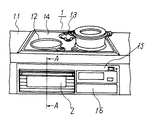
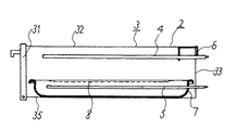
図1〜図3は、本発明の加熱調理装置における実施の形態1を説明するものであって、図1は本発明の加熱調理装置の一例としての電磁誘導加熱式の加熱調理装置の外観図、図2は図1のA−A線に沿った概略断面図、図3は図2に含まれている、前記ロースター部の一例としてのロースターケースの一部破断図を含む概略斜視図である。図1〜図3において、実施の形態1の加熱調理装置1は、流し台11に埋め込まれており、その上部には加熱コイル部12や加熱ヒーター部13を設けた結晶化ガラス製などのトッププレート部14があり、トッププレート部14の下に、基板類や電気回路などを含む部位15、制御パネル部16および加熱調理装置本体2を有する。
【0012】
加熱調理装置本体2は、めっき鋼鈑加工のロースターケース3で囲われており、ロースターケース3は、当該ケース3の前面にある扉部31、上面32、後方面33、側面34、および底部35から構成された直方箱体である。またロースターケース3内には、上面32および側面34に支持固定された上部加熱ヒーター4、後方面33に固定された下部加熱ヒーター5、後方面33の上部一角に設けられた排気口6、底部35上に置かれた受け皿7、および受け皿7上に載置された焼き網8が設けられている。下部加熱ヒーター5は、受け皿7の側面に設けられたヒーター挿通孔73に挿通されて受け皿7の底面上に延在しており、また受け皿7は、ヒーター挿通孔73の存在によりにロースターケース3に対して出し入れ可能となっている。
【0013】
焼き網8上に被調理体たる魚や肉などが置かれて、上部加熱ヒーター4および下部加熱ヒーター5により焼かれる。しかして実施の形態1においては、ロースターケース3自体は加熱調理中の上記被調理体を直接囲む囲み体に該当し、排気口6を備えた後方面33の内面は、前記排気ガス接触面に該当する。また、通常の加熱調理においては、上面32の内面即ち天井面および後方面33の内面は、少なくとも350℃程度、多くの場合に400℃程度に達するので前記第一面に該当し、一方、扉部31および左右の両側面34の各内面は、多くの場合に250℃以下、例えば150℃〜230℃程度に保持されるので前記第二面に該当する。よって上記第一面該当面上には耐熱性塗装膜(図示せず)が設けられており、また上記第二面該当面上には撥水性塗装膜(図示せず)が設けられている。
【0014】
本発明において、加熱調理中の到達温度が上記被調理体から発生する有機物が自然に熱分解するような高温に達する面には耐熱性塗装膜の施与は不要であり、一方、有機物が付着しても、それがこびり付くことなく清掃除去が容易な低温面には撥水性塗装膜の施与は不要である。したがって上記第一面としては、加熱調理中の到達温度が300℃〜450℃程度、特に350℃〜400℃程度である面が好ましく、上記第二面としては、同到達温度が100℃〜250℃程度、特に150℃〜230℃程度である面が好ましい。なお上記囲み体の一部の面部分は、250℃より高く300℃より低い中間温度となることがあるが、かかる面部分は多くの場合に面積的に少量であるので、耐熱性塗装膜または撥水性塗装膜を施与しておいても実際上問題はない。
【0015】
なおロースターケース3自体は囲み体の一例と上記したが、ロースターケース3の底部35上には受け皿7が置かれているので、被調理体を直接囲む囲み体の下面は、厳密には底部35でなく受け皿7の内底面であって、当該内底面には被調理体から発生する有機物が付着する。ところで受け皿7は、調理終了の度毎にロースターケース3から容易に取り出し得て、また手軽に清掃され得るものであるので、本発明においては受け皿7の内底面に前記耐熱性塗装膜あるいは前記撥水性塗装膜を設けてもよく、設けなくてもよい。あるいは、ほうろう処理膜などが形成されてもよい。以上の諸事項は、後続の実施の形態においても該当する。
【0016】
耐熱性塗装膜は、上記第一面に設けられて、当該耐熱性塗装膜上に付着する被調理体から発生する有機物を酸化分解する作用を奏するものであって、次の基準試験に合格するものが用いられる。
【0017】
基準試験;被試験の対象とされる耐熱性塗装膜を形成する耐熱性塗料を50mm×74mm角のステンレス平板の片面に塗布し、加熱乾燥して膜厚100μm程度の耐熱性塗装膜を形成してなる試験片を作成し、これをアンモニアガス含有高温空気(アンモニアガス含有量;60重量ppm、温度;350℃)を満たした容積1.6リットルのガラス容器中に投入し、密閉して10分間放置する。その後、上記試験片を取り出してガラス容器中の高温空気のアンモニアガス含有量を測定し、アンモニアガス含有量が30重量ppm以下となっていれば合格と判定し、また10重量ppm以下となっていれば特に好ましいものと判定する。
【0018】
上記基準試験に合格する耐熱性塗装膜を形成し得る耐熱性塗料としては、少なくとも300℃の高温度に耐える耐熱性塗膜を形成し得る膜形成媒体と被調理体から発生する有機物を酸化分解する作用を有する触媒とを含むもの、好ましくはさらに上記有機物を吸着する吸着剤を含むものが例示される。また上記の触媒としては、二酸化マンガン、白金、パラジウム、あるいはその他の、上記有機物を酸化分解する触媒作用を示すことが斯界で公知あるいは周知のものが制限なく用いられ、吸着剤としては、ゼオライト、ケイ酸ジルコニウム、酸化チタン、あるいはその他の、上記有機物のガス、ミスト、あるいは液化粒子を吸着する作用を示す斯界で公知あるいは周知のものが制限なく用いられる。耐熱性塗膜は、吸着剤を含むことにより被調理体から発生する有機物を吸着し易くなり、吸着した有機物は上記触媒により分解されるので、結果的に耐熱性塗膜による上記有機物の分解処理能力が増大する。また上記膜形成媒体としては、耐熱性の樹脂、例えばシリコーン系樹脂などが用いられる。
【0019】
上記触媒の使用量は、上記膜形成媒体100重量部あたり2〜50重量部程度、好ましくは5〜30重量部程度が適当であり、吸着剤の使用量は、上記膜形成媒体100重量部あたり0.1〜10重量部程度、好ましくは0.5〜5重量部程度が適当である。なお耐熱性塗料は、上記の触媒や吸着剤以外に、顔料、レベリング剤、分散助剤、あるいはその他の配合剤を通常量含んでいてもよく、市販品としては例えばオキツモ社製の商品名No.6347やNo.6227などが例示される。
【0020】
撥水性塗装膜は、上記第二面に設けられて、当該撥水性塗装膜上に付着する被調理体から発生する有機物の酸化分解が不十分の状態でこびりついても、その撥水性に基づいて当該こびりつき層を容易に清掃除去を可能にする作用を奏するものであって、20℃における純水の接触角が少なくとも50度、特に少なくとも70度のものが好ましい。なお撥水性塗装膜は、低温度の上記第二面に設けられるといえども、上記第二面でも200℃以上の高温度に曝されることがあるので、撥水性塗装膜は、少なくとも200℃以上の熱変形温度を有する耐熱性と溶剤可溶性とを備えた塗装膜基体樹脂、例えばポリエーテルスルフォン、ポリイミド、ポリアミドイミドなど、と撥水性付与剤としてのフッ素系樹脂、例えばポリクロロトリフルオロエチレン、ポリフッ化ビニリデンなど、との混合系樹脂が用いられ、清掃性を良好にするためにはフッ素系樹脂は、塗装膜基体樹脂100重量部あたり50〜200重量部程度、好ましくは100〜150重量部程が適当である。上記撥水性塗装膜を形成し得る撥水性塗料の市販品としては、例えばオキツモ社製の商品名NA501−BLが例示される。
【0021】
実施の形態1においては、具体的には、上記第一面該当面上には、オキツモ社製の耐熱性塗料、商品名No.6347が塗布され、280℃15分で乾燥して膜厚100μmの塗装膜が形成されている。また上記第二面該当面には、オキツモ社製の撥水性塗料、商品名NA501−BLが塗布され、380℃で15分間乾燥して膜厚15μmの塗装膜が形成されている。
【0022】
実施の形態1の加熱調理装置を用いて、焼き網8上でサンマ3匹の姿焼きを行い、焼いた後で、受け皿7および焼き網8を取り出して清掃、洗浄し、両側面34を柄の長いブラシで清掃した。この操作を1サイクルとし、これを5サイクル行った後におけるロースターケース3の各内面の油脂残りの程度を目視により調べた結果を表1に示す。なお表1には、上記目視に際に嗅覚により感じた臭気残りの程度についても参考までに示す。後続の実施の形態並びに比較例についても同様である。
【0023】
実施の形態2.
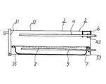
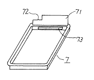
図4〜図6は、本発明の加熱調理装置における実施の形態2を説明するものであって、図4は前記図1のA−A線に沿った、前記図2に対応する他の概略断面図であり、図5は図4に含まれている前記囲み体の他の例の本体となるカバー9の斜視図、図6は受け皿7の斜視図である。図4〜図6において、めっき鋼鈑製のカバー9は、ロースターケース3内に且つ上部加熱ヒーター4と焼き網8とを覆うように受け皿7上に載置されており、ロースターケース3の扉部31と後方面33のそれぞれと対向する面の無い、長手方向に直行する方向の断面がコ字型のものであって、上部加熱ヒーター4と近接する上面91、上面91に連なる両側面92、および上面91に設けられて上部加熱ヒーター4を保持する保持部を挿通するための切り込み部93を有すものである。両側面92の下端は、焼き網8の位置を越えて下部加熱ヒーター5の近傍まで延在している。また受け皿7は、実施の形態1において用いられたそれとは、後方面33と対向するように、後方面71が取り付けられており、後方面71には排気口6に通じる切り込み部72が設けられている。カバー9は、ロースターケース3の側面34の内面に凸部などの設置手段を設けることなく設置されている。
【0024】
実施の形態2においては、加熱調理中の被調理体を直接囲む囲み体は、ロースターケース3の扉部31、カバー9、および受け皿7に設けられた後方面71であって、後方面71は排気口6に通じる切り込み部72を有することにより排気口6に向かう排気ガスが接触するので、前記排気ガス接触面に一例に該当する。しかして前記第一面は、上面91と後方面71の各内面であり、前記第二面は、扉部31と両側面92の各内面であるので、上記第一面および上記第二面には、実施の形態1の場合と同じ耐熱性塗料と撥水性塗料とが使用され、且つ同じ方法にてそれぞれ耐熱性塗料膜と撥水性塗料膜とが設けられている。
【0025】
実施の形態2の加熱調理装置を用いて実施の形態1と同様に魚焼きを行い、魚焼き後にカバー9、受け皿7および焼き網8を取り出して、カバー9の上面91、両側面92、および受け皿7の後方面71、受け皿7および焼き網8を清掃、洗浄した。この操作を1サイクルとし、これを5サイクル行った後におけるロースターケース3、カバー9、およびの後方面71での各内面の油脂残りの程度を目視により調べた結果を表1に示す。
【0026】
実施の形態3.
実施の形態3においては、前記実施の形態2と同じ加熱調理装置を用い、但し調理条件を後記するように変えることによってカバー9の両側面92も350℃程度に達することとなるので、両側面92の内面にも耐熱性塗料膜が施されている。よって実施の形態3は、実施の形態2とは両側面92の内面にも耐熱性塗料膜が施された点において異なり、その他の構成は同じである。
【0027】
実施の形態3の加熱調理装置を用いて、大型サンマ5匹の姿焼きを行い、そのためにカバー9の両側面92も350℃程度に達した。魚焼き後は、実施の形態2と同様に清掃、洗浄した。この操作を1サイクルとし、これを5サイクル行った後におけるロースターケース3、カバー9、およびの後方面71での油脂残りの程度を目視により調べた結果を表1に示す。
【0028】
実施の形態4.
図7および図8は、本発明の加熱調理装置における実施の形態4を説明するものであって、図7は前記図1のA−A線に沿った、前記図2に対応するさらに他の概略断面図であり、図8は上部加熱ヒーター4および下部加熱ヒーター5の概略平面図である。上部加熱ヒーター4と下部加熱ヒーター5とは、略同形同サイズであって、図7および図8においては上部加熱ヒーター4はY字状を呈していて、高温度となるU字状の加熱部41と直線状部42とから構成されており、直線状部42の根部421は、覆い部43により覆われている。したがって加熱調理時においては、覆い部43により覆われずにロースターケース3内に露出している直線状部42の露出部422と加熱部41との各表面に被調理体から発生する有機物が接触するが、加熱部41の表面は高温度であるので接触有機物は直ちに分解する。一方、露出部422は250℃以下の第二面となる。
【0029】
同様に、下部加熱ヒーター5もY字状を呈していて、高温度となるU字状の加熱部51と直線状部52とから構成されており、直線状部52の根部521は、覆い部53により覆われている。したがって加熱調理時においては、露出部522は250℃以下の第二面となる。よって、実施の形態4においては、露出部422と露出部522の各表面に実施の形態1の場合と同じ撥水性塗料膜が設けられている。よって実施の形態4は、実施の形態1とは露出部422と露出部522の各表面に撥水性塗料膜が設けられている点において異なり、その他の構成は同じである。実施の形態4の加熱調理装置を用いて実施の形態1と同じ試験をした結果を表1に示す。
【0030】
比較例1.
実施の形態1と同じ加熱調理装置を用い、但しロースターケース3の上面32、側面34および後方面33の各内面の全てに実施の形態1と同じ耐熱性塗装膜が形成されている。比較例1の加熱調理装置1を用いて実施の形態1と同じ試験をした結果を表1に示す。
【0031】
比較例2.
実施の形態2と同じ加熱調理装置を用い、但しカバー3の上面91、側面92、及び受け皿7の後方面71の各内面の全ては、ほうろう処理膜が形成されている。比較例2の加熱調理装置1を用いて実施の形態2と同じ試験をした結果を表1に示す。
【0032】
比較例3.
実施の形態1と同じ加熱調理装置を用い、但し、ロースターケース3の側面34の内面のみに実施の形態1と同じ撥水性塗装膜が形成されている。比較例3の加熱調理装置を用いて実施の形態1と同じ試験をした結果を表1に示す。
【0033】
【表1】
【0034】
表1に示すように、実施の形態1および実施の形態4のようなロースターケース3自体が囲み体である場合、耐熱性塗装膜を設けた面では油脂残りはなく、撥水性塗装膜を設けた面では油脂のこびり付物の清掃除去は極めて容易であって、清掃後においては、ロースターケース3内の残留臭気は表記するように僅かであった。同様のことがカバー9を用いた実施の形態2および実施の形態3についても言える。これに対して、比較例1、比較例2、および比較例3では、魚焼き後の油脂残りがあり、またそれらの清掃除去が困難であった。
【0035】
【発明の効果】
本発明の加熱調理装置は、以上説明したように、加熱調理装置の使用中における到達温度が少なくとも300℃に達する第一面と250℃以下の第二面とを有する加熱調理装置、就中、電磁誘導加熱式の加熱調理装置であって、上記第一面の少なくとも一部の面上には被調理体から発生する有機物を酸化分解する触媒を含む耐熱性塗装膜が設けられ、上記第二面の少なくとも一部の面上には撥水性塗装膜が設けられたことを特徴とするものである。高温度の第一面に付着する上記有機物は耐熱性塗装膜により酸化分解され、一方、低温度の第二面に付着してこびり付いた有機物は撥水性塗装膜の存在により容易に清掃除去が可能であるので、本発明の加熱調理装置は、繰り返し使用しても、簡単な清掃により清潔に維持できる大きな効果がある。
【図面の簡単な説明】
【図1】本発明の加熱調理装置における実施の形態1の外観図。
【図2】図1のA−A線に沿った概略断面図。
【図3】図2に含まれているロースターケースの一部破断図を含む概略斜視図。
【図4】本発明の加熱調理装置における実施の形態2の、図1のA−A線に沿った他の概略断面図。
【図5】図4に含まれているカバー9の斜視図。
【図6】図4に含まれている受け皿7の斜視図。
【図7】本発明の加熱調理装置における実施の形態4の、図1のA−A線に沿ったさらに他の概略断面図。
【図8】図7に含まれる上部加熱ヒーター4および下部加熱ヒーター5の概略平面図。
【符号の説明】
1 加熱調理装置、2 加熱調理装置本体、3 ロースターケース、
31 扉部、32 上面、33 後方面、34 側面、35 底部、
4 上部加熱ヒーター、5 下部加熱ヒーター、6 排気口、7 受け皿、
71 後方面、72 切り込み部、8 焼き網、9 カバー、91 上面91、92 側面、93 切り込み部。[0001]
TECHNICAL FIELD OF THE INVENTION
The present invention relates to a cooking device, and more particularly to a cooking device of an electromagnetic induction heating type, which is suitable for general household use.
[0002]
[Prior art]
When a cooking device heats fish, meat, or other objects to be cooked, various organic substances such as oils, volatile components, and decomposed components are generated from the objects to be cooked, and the organic substances are contained in the roaster section of the cooking device. There is a problem in that it adheres to and contaminates the surface of the wall or the surface of the member exposed in the roaster unit, causing uncomfortable feeling in the next cooking. To solve this problem, a proposal for improving the corrosion resistance and heat resistance of the roaster part by forming an enamel treatment film on stainless steel used on the wall surface of the roaster part of the heating cooking device is disclosed in, for example, Patent Document 1 described below. Have been. Further, in Patent Document 2 described below, a lower coating layer made of a paint in which an absorbent for absorbing fats and oils, an oxidation catalyst, and a polymerization inhibitor are mixed, and an oxidation catalyst are compounded on the wall surface of the cooking device. It is disclosed that an upper coating layer made of a paint is provided, and a catalyst film coated with a lubricating material made of a resin coating having abrasion resistance and heat resistance is further applied on the upper coating layer. Further, Patent Document 3 described below discloses a heating cooking device in which a heating chamber is configured by a wall material made of a non-adhesive coating film using a fluororesin.
[0003]
[Patent Document 1]
Japanese Patent Application Laid-Open No. 9-42687 (Claims)
[Patent Document 2]
JP-A-10-202112 (Claims)
[Patent Document 3]
JP-A-2002-267176 (Claims)
[0004]
By the way, only the enamel treatment in Patent Document 1 does not decompose the fish oil and fat, and the fish oil and fat remains, and the formation of the enamel treatment film itself requires a high temperature of 600 ° C. to 700 ° C. There is a problem that the formation cost of the processing film increases. Further, in Patent Document 2, the formation of a coating film containing an oxidative decomposition catalyst is at a temperature of about 300 ° C., and thus the formation of the coating film itself is low in cost, but has the following problems.
[0005]
That is, in order for the decomposition by the oxidative decomposition catalyst to efficiently proceed on the above-mentioned coated film, a high temperature of at least 300 ° C. or more is usually required, and the fish was baked in a roaster of a conventional cooking device. In this case, since the upper surface in the roaster part is at 350 ° C. to 400 ° C., the decomposition of fish fats and odors proceeds effectively. However, in many cases, the side surface is only about 180 ° C. to 210 ° C., which causes not only the problem that the decomposition is insufficient, but also sticks to the coating film while the decomposition is insufficient, and the removal after cooking is difficult. Some problems are extremely difficult.
[0006]
Further, in the technique of Patent Document 3, formation of only a water-repellent fluororesin has a problem that the oil and fat itself cannot be oxidized and decomposed even if the oil and fat can be easily cleaned. Further, when a fluororesin coating film is formed on the upper surface of the roaster part, the upper surface temperature is 400 ° C. during fish baking and 450 ° C. during empty baking, so that there is a problem that toxic gas such as phosgene is generated from the fluororesin. .
[0007]
As described above, in the conventional heating and cooking apparatus, it is necessary to simultaneously solve both the problems of oxidative decomposition of fats and oils generated when roasting fish in the roaster part and sticking of fats and oils on the low-temperature surface in the roaster part. Despite this, it is still in a state of being quiet.
[0008]
[Problems to be solved by the invention]
SUMMARY OF THE INVENTION The present invention has been made in view of the above circumstances in the prior art, and has as its object to provide a heating cooking device capable of simultaneously solving both the problems of oxidative decomposition of fats and oils in the heating cooking device and sticking at a low temperature in the heating cooking device. And
[0009]
[Means for Solving the Problems]
The heating cooking device of the present invention is a heating cooking device having a first surface that reaches a temperature of at least 300 ° C. during use of the heating cooking device and a second surface of 250 ° C. or less, wherein at least the first surface A heat-resistant coating film containing a catalyst for oxidizing and decomposing organic substances generated from the object to be cooked was provided on some surfaces, and a water-repellent coating film was provided on at least a portion of the second surface. It is characterized by the following.
[0010]
BEST MODE FOR CARRYING OUT THE INVENTION
In the following, the same reference numerals are given to the same parts or the same display, and the description may be omitted.
[0011]
Embodiment 1 FIG.
1 to 3 illustrate a first embodiment of a heating and cooking apparatus according to the present invention. FIG. 1 is an external view of an electromagnetic induction heating type heating and cooking apparatus as an example of the heating and cooking apparatus according to the present invention. FIG. 2 is a schematic sectional view taken along the line AA of FIG. 1, and FIG. 3 is a schematic perspective view including a partially cutaway view of a roaster case as an example of the roaster section included in FIG. . 1 to 3, the cooking device 1 according to the first embodiment is embedded in a sink 11, and a top plate made of crystallized glass or the like provided with a heating coil unit 12 and a heating heater unit 13 above the sink 11. There is a unit 14, and below the top plate unit 14, a part 15 including boards, electric circuits, and the like, a control panel unit 16, and the cooking device main body 2 are provided.
[0012]
The heating cooking device main body 2 is surrounded by a roaster case 3 made of plated steel plate, and the roaster case 3 is provided with a door portion 31, an upper surface 32, a rear surface 33, a side surface 34, and a bottom portion 35 on the front surface of the case 3. It is a rectangular box composed of: In the roaster case 3, an upper heater 4 supported and fixed to the upper surface 32 and the side surface 34, a lower heater 5 fixed to the rear surface 33, an exhaust port 6 provided at an upper corner of the rear surface 33, and a bottom portion A saucer 7 placed on the tray 35 and a grill 8 placed on the saucer 7 are provided. The lower heater 5 is inserted into a heater insertion hole 73 provided on a side surface of the tray 7 and extends on the bottom surface of the tray 7. It is possible to put in and take out.
[0013]
Fish or meat to be cooked is placed on the grill 8 and is grilled by the upper heater 4 and the lower heater 5. Thus, in the first embodiment, the roaster case 3 itself corresponds to an enclosure directly surrounding the object to be cooked during heating and cooking, and the inner surface of the rear surface 33 provided with the exhaust port 6 corresponds to the exhaust gas contact surface. Applicable. In normal cooking, the inner surface of the upper surface 32, that is, the inner surface of the ceiling surface and the inner surface of the rear surface 33 reaches at least about 350 ° C., and often about 400 ° C., and thus corresponds to the first surface. Since the inner surfaces of the portion 31 and the left and right side surfaces 34 are kept at 250 ° C. or less in many cases, for example, at approximately 150 ° C. to 230 ° C., they correspond to the second surface. Accordingly, a heat-resistant coating film (not shown) is provided on the surface corresponding to the first surface, and a water-repellent coating film (not shown) is provided on the surface corresponding to the second surface.
[0014]
In the present invention, it is not necessary to apply a heat-resistant coating film on a surface where the temperature reached during cooking is high enough to naturally decompose the organic matter generated from the object to be cooked. However, it is not necessary to apply a water-repellent coating film to a low-temperature surface where it is easy to clean and remove without sticking. Therefore, the first surface is preferably a surface having a temperature of about 300 ° C. to 450 ° C., particularly about 350 ° C. to 400 ° C. during heating, and the second surface is preferably a temperature of 100 ° C. to 250 ° C. A surface having a temperature of about 150C, particularly about 150C to 230C is preferable. Note that some surface portions of the above-mentioned enclosure may have an intermediate temperature higher than 250 ° C. and lower than 300 ° C., but since such surface portions are often small in area, a heat-resistant coating film or Even if a water-repellent coating film is applied, there is no practical problem.
[0015]
Although the roaster case 3 itself has been described as an example of the surrounding body, the saucer 7 is placed on the bottom 35 of the roaster case 3, so that the lower surface of the surrounding body directly surrounding the object to be cooked is strictly a bottom 35. However, the organic matter generated from the object to be cooked adheres to the inner bottom surface of the tray 7 and not to the inner bottom surface. By the way, the tray 7 can be easily taken out of the roaster case 3 each time cooking is completed and can be easily cleaned. Therefore, in the present invention, the heat-resistant coating film or the repellent film is formed on the inner bottom surface of the tray 7. An aqueous coating film may or may not be provided. Alternatively, an enameled film or the like may be formed. The above items also apply to the following embodiments.
[0016]
The heat-resistant coating film is provided on the first surface, and has an action of oxidatively decomposing organic substances generated from the object to be cooked adhered on the heat-resistant coating film, and passes the following standard test. Things are used.
[0017]
Reference test: A heat-resistant paint for forming a heat-resistant paint film to be tested is applied to one surface of a 50 mm × 74 mm square stainless steel plate, and dried by heating to form a heat-resistant paint film having a thickness of about 100 μm. A test piece was prepared and placed in a 1.6 liter glass container filled with ammonia gas-containing high-temperature air (ammonia gas content; 60 ppm by weight, temperature: 350 ° C.), sealed and sealed. Leave for a minute. Thereafter, the test piece was taken out and the ammonia gas content of the high-temperature air in the glass container was measured. If the ammonia gas content was 30 ppm by weight or less, it was judged to be acceptable, and 10 ppm by weight or less. Is determined to be particularly preferable.
[0018]
The heat-resistant paint capable of forming a heat-resistant coating film that passes the above-described standard test includes a film-forming medium capable of forming a heat-resistant coating film that can withstand a high temperature of at least 300 ° C. and an organic substance generated from an object to be cooked by oxidative decomposition. And those containing an adsorbent that adsorbs the above-mentioned organic substances. Further, as the catalyst, manganese dioxide, platinum, palladium, or other, known or known in the art to exhibit a catalytic action to oxidatively decompose the organic substance is used without limitation, as the adsorbent, zeolite, Any known or well-known zirconium silicate, titanium oxide, or any other substance having an action of adsorbing a gas, mist, or liquefied particle of the above-mentioned organic substance can be used without limitation. The heat-resistant coating film easily adsorbs organic substances generated from the cooked object by containing the adsorbent, and the adsorbed organic substances are decomposed by the catalyst. As a result, the organic substance is decomposed by the heat-resistant coating film. Ability increases. As the film forming medium, a heat-resistant resin such as a silicone-based resin is used.
[0019]
The amount of the catalyst used is about 2 to 50 parts by weight, preferably about 5 to 30 parts by weight per 100 parts by weight of the film forming medium, and the amount of the adsorbent used is 100 parts by weight of the film forming medium. A suitable amount is about 0.1 to 10 parts by weight, preferably about 0.5 to 5 parts by weight. The heat-resistant paint may contain a usual amount of a pigment, a leveling agent, a dispersing aid, or other compounding agents, in addition to the above-mentioned catalyst and adsorbent, and as a commercial product, for example, product name No. . 6347 or No. 6; 6227 and the like.
[0020]
The water-repellent coating film is provided on the second surface, and even if the organic substance generated from the object to be cooked adhered to the water-repellent coating film sticks in an insufficiently oxidized state, the water-repellent coating film is based on the water repellency. It has an effect of easily cleaning and removing the sticking layer, and preferably has a contact angle of pure water at 20 ° C. of at least 50 degrees, particularly at least 70 degrees. Although the water-repellent coating film is provided on the second surface at a low temperature, the second surface may be exposed to a high temperature of 200 ° C. or more. Paint film base resin having heat resistance and solvent solubility having the above heat deformation temperature, such as polyether sulfone, polyimide, polyamideimide, etc., and a fluorine-based resin as a water repellent, such as polychlorotrifluoroethylene, A mixed resin with polyvinylidene fluoride or the like is used. In order to improve the cleaning property, the fluororesin is used in an amount of about 50 to 200 parts by weight, preferably 100 to 150 parts by weight per 100 parts by weight of the coating film base resin. The process is appropriate. As a commercial product of the water-repellent paint capable of forming the above-mentioned water-repellent coating film, for example, a product name NA501-BL manufactured by Okitsumo is exemplified.
[0021]
In the first embodiment, specifically, on the surface corresponding to the first surface, a heat-resistant paint manufactured by Okitsumo Co., Ltd., trade name No. 6347 is applied and dried at 280 ° C. for 15 minutes to form a coating film having a thickness of 100 μm. On the surface corresponding to the second surface, a water-repellent paint manufactured by Okitsumo Co., Ltd., trade name NA501-BL is applied, and dried at 380 ° C. for 15 minutes to form a coating film having a thickness of 15 μm.
[0022]
Using the heating and cooking apparatus of the first embodiment, three saury are grilled on the grill 8, and after baking, the saucer 7 and the grill 8 are taken out, cleaned and washed, and both side surfaces 34 are patterned. Cleaned with a long brush. This operation was defined as one cycle, and the results of visually inspecting the degree of oil and grease remaining on each inner surface of the roaster case 3 after performing five cycles are shown in Table 1. Table 1 also shows, for reference, the degree of the odor remaining felt by the sense of smell during the visual observation. The same applies to the following embodiments and comparative examples.
[0023]
Embodiment 2 FIG.
4 to 6 illustrate a second embodiment of the heating and cooking apparatus of the present invention. FIG. 4 is another schematic diagram corresponding to FIG. 2 along the line AA in FIG. 5 is a perspective view of a cover 9 serving as a main body of another example of the enclosure included in FIG. 4, and FIG. 6 is a perspective view of a tray 7. 4 to 6, a cover 9 made of a plated steel plate is placed on the tray 7 so as to cover the upper heater 4 and the grill 8 in the roaster case 3, and the door of the roaster case 3 is provided. There is no surface facing each of the portion 31 and the rear surface 33, and the cross section in the direction perpendicular to the longitudinal direction is U-shaped, and the upper surface 91 is close to the upper heater 4, and both side surfaces 92 connected to the upper surface 91. , And a cut-out portion 93 provided on the upper surface 91 for inserting a holding portion for holding the upper heater 4. The lower ends of both side faces 92 extend beyond the position of the grill 8 to the vicinity of the lower heater 5. Further, the receiving tray 7 has a rear surface 71 attached thereto so as to be opposed to the rear surface 33 used in the first embodiment, and the rear surface 71 is provided with a cutout 72 communicating with the exhaust port 6. ing. The cover 9 is installed on the inner surface of the side surface 34 of the roaster case 3 without providing any installation means such as a protrusion.
[0024]
In the second embodiment, the surrounding body directly surrounding the object to be cooked during heating and cooking is the rear surface 71 provided on the door portion 31, the cover 9, and the tray 7 of the roaster case 3, and the rear surface 71 is Since the exhaust gas coming toward the exhaust port 6 comes into contact by having the cut portion 72 communicating with the exhaust port 6, this corresponds to an example of the exhaust gas contact surface. Thus, the first surface is the inner surface of the upper surface 91 and the rear surface 71, and the second surface is the inner surface of the door portion 31 and both side surfaces 92. Uses the same heat-resistant paint and water-repellent paint as in the first embodiment, and is provided with a heat-resistant paint film and a water-repellent paint film by the same method.
[0025]
Fish is grilled in the same manner as in Embodiment 1 using the heating and cooking apparatus of Embodiment 2, and after the grilling of fish, the cover 9, the saucer 7 and the grill 8 are taken out, and the upper surface 91, both side surfaces 92, and The rear surface 71 of the tray 7, the tray 7, and the grill 8 were cleaned and washed. This operation was defined as one cycle, and the results obtained by visually examining the degree of oil and grease remaining on each inner surface of the roaster case 3, the cover 9, and the rear surface 71 after performing five cycles are shown in Table 1.
[0026]
Embodiment 3 FIG.
In the third embodiment, the same heating and cooking device as in the second embodiment is used, but the cooking conditions are changed as described below, so that both sides 92 of the cover 9 also reach about 350 ° C. A heat-resistant paint film is also applied to the inner surface of 92. Therefore, the third embodiment is different from the second embodiment in that a heat-resistant paint film is also applied to the inner surfaces of both side surfaces 92, and the other configuration is the same.
[0027]
Using the heating and cooking apparatus of the third embodiment, five large saury were grilled, and both side surfaces 92 of the cover 9 reached about 350 ° C. After grilling the fish, cleaning and washing were performed in the same manner as in the second embodiment. This operation was defined as one cycle, and the results of visually inspecting the degree of oil and grease remaining on the roaster case 3, the cover 9, and the rear surface 71 after performing the five cycles are shown in Table 1.
[0028]
Embodiment 4 FIG.
7 and 8 illustrate a fourth embodiment of the heating and cooking apparatus according to the present invention. FIG. 7 is a view corresponding to FIG. 2 and taken along line AA in FIG. FIG. 8 is a schematic plan view of the upper heater 4 and the lower heater 5. The upper heater 4 and the lower heater 5 have substantially the same shape and the same size. In FIGS. 7 and 8, the upper heater 4 has a Y-shape, and has a U-shape heating at a high temperature. It comprises a portion 41 and a linear portion 42, and the root 421 of the linear portion 42 is covered by a cover 43. Therefore, at the time of cooking, the organic matter generated from the cooked object comes into contact with each surface of the heating portion 41 and the exposed portion 422 of the linear portion 42 which is not covered by the cover portion 43 and is exposed in the roaster case 3. However, since the surface of the heating unit 41 is at a high temperature, the contact organic matter is immediately decomposed. On the other hand, the exposed portion 422 is a second surface at 250 ° C. or lower.
[0029]
Similarly, the lower heater 5 also has a Y-shape, and is composed of a U-shaped heating portion 51 and a linear portion 52 at a high temperature, and a root portion 521 of the linear portion 52 has a covering portion. 53. Therefore, during heating cooking, the exposed portion 522 becomes a second surface at 250 ° C. or lower. Therefore, in the fourth embodiment, the same water-repellent paint film as in the first embodiment is provided on each surface of the exposed portion 422 and the exposed portion 522. Therefore, the fourth embodiment is different from the first embodiment in that a water-repellent paint film is provided on each surface of the exposed portion 422 and the exposed portion 522, and other configurations are the same. Table 1 shows the results of the same test as in Embodiment 1 using the cooking device of Embodiment 4.
[0030]
Comparative Example 1
The same heating and cooking device as that of the first embodiment is used, except that the same heat-resistant coating film as that of the first embodiment is formed on all the inner surfaces of the upper surface 32, the side surface 34, and the rear surface 33 of the roaster case 3. Table 1 shows the results of the same test as in Embodiment 1 using the heating and cooking device 1 of Comparative Example 1.
[0031]
Comparative Example 2.
The same heating and cooking device as that of the second embodiment is used, except that the inner surface of the upper surface 91 and the side surface 92 of the cover 3 and the inner surface of the rear surface 71 of the tray 7 are all formed with an enameled film. Table 1 shows the results of the same test as in Embodiment 2 using the cooking device 1 of Comparative Example 2.
[0032]
Comparative Example 3
The same heating and cooking apparatus as that of the first embodiment is used, except that the same water-repellent coating film as that of the first embodiment is formed only on the inner surface of the side surface 34 of the roaster case 3. Table 1 shows the results of the same test as in Embodiment 1 using the heating cooking device of Comparative Example 3.
[0033]
[Table 1]
[0034]
As shown in Table 1, when the roaster case 3 itself is an enclosing body as in the first and fourth embodiments, there is no grease remaining on the surface on which the heat-resistant coating film is provided, and the water-repellent coating film is provided. On the other hand, it was very easy to clean and remove the adhered matter of the oil and fat, and the residual odor in the roaster case 3 was slight as shown after cleaning. The same applies to the second and third embodiments using the cover 9. On the other hand, in Comparative Examples 1, 2 and 3, there were oils and fats left after grilling fish, and it was difficult to remove them after cleaning.
[0035]
【The invention's effect】
As described above, the heating cooking device of the present invention has a first surface that reaches a temperature of at least 300 ° C. and a second surface of 250 ° C. or less during use of the heating cooking device. An electromagnetic induction heating type cooking device, wherein at least a part of the first surface is provided with a heat-resistant coating film including a catalyst for oxidatively decomposing organic substances generated from a cooked object, A water-repellent coating film is provided on at least a part of the surface. The organic substances adhering to the high temperature first surface are oxidized and decomposed by the heat-resistant coating film, while the organic substances adhering to the low temperature second surface and sticking can be easily cleaned and removed due to the presence of the water-repellent coating film. Therefore, the heating and cooking apparatus of the present invention has a great effect that even if it is used repeatedly, it can be kept clean by simple cleaning.
[Brief description of the drawings]
FIG. 1 is an external view of a heating cooking device according to a first embodiment of the present invention.
FIG. 2 is a schematic sectional view taken along line AA of FIG.
FIG. 3 is a schematic perspective view including a partially cutaway view of the roaster case included in FIG. 2;
FIG. 4 is another schematic cross-sectional view of the heating cooking device according to the second embodiment of the present invention, taken along line AA of FIG. 1;
FIG. 5 is a perspective view of a cover 9 included in FIG. 4;
FIG. 6 is a perspective view of a tray 7 included in FIG. 4;
7 is still another schematic cross-sectional view of the fourth embodiment of the heating and cooking apparatus of the present invention, taken along line AA of FIG.
8 is a schematic plan view of an upper heater 4 and a lower heater 5 included in FIG.
[Explanation of symbols]
1 cooking device, 2 cooking device body, 3 roaster case,
31 door, 32 top, 33 rear, 34 side, 35 bottom,
4 upper heater, 5 lower heater, 6 exhaust port, 7 saucer,
71 rear surface, 72 cut portion, 8 grid, 9 cover, 91 upper surface 91, 92 side surface, 93 cut portion.