JP2004192065A - Coordinate detection apparatus - Google Patents
Coordinate detection apparatus Download PDFInfo
- Publication number
- JP2004192065A JP2004192065A JP2002355870A JP2002355870A JP2004192065A JP 2004192065 A JP2004192065 A JP 2004192065A JP 2002355870 A JP2002355870 A JP 2002355870A JP 2002355870 A JP2002355870 A JP 2002355870A JP 2004192065 A JP2004192065 A JP 2004192065A
- Authority
- JP
- Japan
- Prior art keywords
- touch point
- coordinate
- input surface
- light
- coordinate input
- Prior art date
- Legal status (The legal status is an assumption and is not a legal conclusion. Google has not performed a legal analysis and makes no representation as to the accuracy of the status listed.)
- Granted
Links
Images









Abstract
Description
【0001】
【発明の属する技術分野】
この発明は、座標入力面に入力されたタッチ点の座標を検知する座標検知装置に関する。
【0002】
【従来の技術】
現在、ディスプレイ画面と座標入力装置とを一体化し、ディスプレイ画面上をタッチしながらディスプレイ画面に表示される画像を制御することができるタッチパネル付きディスプレイ装置が普及しつつある。また、学校の授業や企業のプレゼンテーション等での利用を想定した、比較的大型のタッチパネル付きディスプレイ装置も知られている。
【0003】
座標入力装置としては、光学式のものが知られている。光学式の座標入力装置では、座標入力面に入力された位置の方向を2方向から検知することにより、その位置の座標を算出する。図19は、従来の光学式の座標検知装置の一例を示している。座標入力装置300は、座標入力面301の両端に配置された光学ユニット303a,303bと、座標を入力する際に使用する座標入力面301と、座標入力面301の三方を取り囲み、進入してきた光を進入してきた方向に再帰的に反射する反射部302a,302b,302cとを有している。
【0004】
光学ユニット303a,303bは、発光部および受光部(図示せず)を有している。発光部は、座標入力面301にほぼ平行に扇形に広がる光を照射し、受光部は、反射部302a,302b,302cで反射され再帰的に戻ってきた光を受光する。座標入力装置300は、2つの光学ユニット303a,303bでそれぞれ検知された光の遮蔽方向(θL,θR)と当該光学ユニット303a,303b間の距離に基づいて、座標入力面301に入力された座標の位置を算出することができる。
【0005】
しかし、例えば、図19に示すように、点Aと点Bとを通る直線上に右側の光学ユニット303aが配置されるような位置関係の点Aと点Bとが同時にタッチされた場合には光学ユニット303aに近い位置の点Aの座標の精度は維持できるが、点Aの本影や半影の影響により、点Bの正確な方向を検知できず、点Bの座標の精度を維持できない。すなわち、光学ユニット303aは、タッチ点Bの座標を推定値としてしか算出できないという不具合がある。
【0006】
このような問題を解決する方法としては、360°回転可能なミラーを設け、2点タッチされたにもかかわらず一の光学ユニットが1点の方向のみしか検知しない場合には、1点しか検知しない光学ユニット側の光をミラーに照射し、ミラーを回転させ、回転角度から2点を検知する技術が知られている(例えば特許文献1参照)。
【0007】
【特許文献1】
特開2002−55770号公報(第4−7頁,第1図)
【0008】
【発明が解決しようとする課題】
しかし、例えば、ユーザが座標入力面に手をついて筆記している場合など、2点の大きさが極端に異なる場合や、2点が近接している場合には、2点を分離して検出するのが困難であるという問題がなお残されている。
【0009】
この発明は上記に鑑みてなされたもので、座標入力面に入力されたタッチ点の座標を正確に算出することのできる座標検知装置を提供することを目的とする。
【0010】
【課題を解決するための手段】
上記目的を達成するため、請求項1にかかる発明は、座標入力面上に入力されたタッチ点の座標を検知する座標検知装置であって、前記座標入力面の第1の辺に近接して配置され、配置された位置を基準とする前記タッチ点の方向であるタッチ点方向を検知する少なくとも2つの第1の方向検知手段と、前記座標入力面の第2の辺に近接して配置され、配置された位置を基準とする前記タッチ点の方向であるタッチ点方向を検知する少なくとも2つの第2の方向検知手段と、前記第1の方向検知手段および前記第2の方向検知手段のうち少なくとも2つの方向検知手段が検知した前記タッチ点方向に基づいてタッチ点座標を算出する算出制御手段とを備えたことを特徴とする。
【0011】
この請求項1の発明によれば、第1の辺と第2の辺にそれぞれ方向検知手段が設けられているので、一方の辺の方向検知手段が検知したタッチ点方向に基づいて、正確にタッチ点座標を算出できない場合であっても、他方の辺の方向検知手段が検知したタッチ点方向に基づいてタッチ点座標を算出することができる。従って、より正確にタッチ点座標を算出することができる。また、一方の辺の方向検知手段が検知したタッチ点方向と、他方の辺の方向検知手段が検知したタッチ点方向との両方に基づいて、正確にタッチ点座標を算出することができる。
【0012】
さらに、第1の辺と第2の辺の両方に方向検知手段を配置することができるので、各方向検知手段の配置位置の自由度が増加し、より適切な位置に各方向検知手段を配置することができる。
【0013】
また、請求項2にかかる発明は、請求項1に記載の座標検知装置であって、前記第2の方向検知手段は、前記座標入力面における前記第1の辺に対向する辺である前記第2の辺に近接して配置されることを特徴とする。
【0014】
この請求項2の発明によれば、対向する2辺にそれぞれ方向検知手段が配置されているので、一方の辺の方向検知手段が検知したタッチ点方向に基づいて、正確にタッチ点座標を算出できない場合であっても、他方の方向検知手段が検知したタッチ点方向に基づいて正確にタッチ点座標を算出することができる。また、一方の辺の方向検知手段が検知したタッチ点方向と、他方の辺の方向検知手段が検知したタッチ点方向との両方に基づいて、正確にタッチ点座標を算出することができる。
【0015】
また、請求項3にかかる発明は、請求項1に記載の座標検知装置であって、前記第2の方向検知手段は、前記座標入力面における前記第1の辺に接する辺である前記第2の辺に近接して配置されることを特徴とする。
【0016】
この請求項3の発明によれば、互いに接する2辺にそれぞれ方向検知手段が配置されているので、一方の辺の方向検知手段が検知したタッチ点方向に基づいて、正確にタッチ点座標を算出できない場合であっても、他方の方向検知手段が検知したタッチ点方向に基づいて正確にタッチ点座標を算出することができる。または、一方の辺の方向検知手段が検知したタッチ点方向と、他方の辺の方向検知手段が検知したタッチ点方向との両方に基づいて、正確にタッチ点座標を算出することができる。
【0017】
また、請求項4にかかる発明は、請求項1から3のいずれか一項に記載の座標検知装置であって、前記第1の方向検知手段と、前記第2の方向検知手段とは、それぞれ異なるタイミングで前記タッチ点方向を検知することを特徴とする。
【0018】
この請求項4の発明によれば、異なる辺に配置される第1の方向検知手段と第2の方向検知手段は、それぞれ異なるタイミング、すなわち交互にタッチ点方向を検知するので、他方の方向検知手段の方向検知に起因した誤検出を防ぐことができる。従って、正確にタッチ点方向を検知することができる。
【0019】
また、請求項5にかかる発明は、請求項4に記載の座標検知装置であって、前記方向検知手段は、前記座標入力面に平行な面に沿って扇状に広がる光を射出する発光手段と、前記座標入力面を通過した光を反射する反射手段からの反射光を受光する受光手段とを有し、前記第1の辺に近接して配置された前記受光手段と、前記第2の辺に近接して配置された前記受光手段とは、それぞれ異なるタイミングで反射光を受光することを特徴とする。
【0020】
この請求項5の発明によれば、異なる辺に配置される受光手段は、それぞれ異なるタイミング、すなわち交互に反射光を受光するので、各受光手段が異なる辺に配置された発光手段により射出された光の反射光を過って受光するのを防ぐことができる。従って、正確にタッチ点方向を検知することができる。
【0021】
また、請求項6にかかる発明は、請求項4または5に記載の座標検知装置であって、前記方向検知手段は、前記座標入力面に平行な面に沿って扇状に広がる光を射出する発光手段と、前記座標入力面を通過した光を反射する反射手段からの反射光を受光する受光手段とを有し、前記第1の辺に近接して配置された前記発光手段と、前記第2の辺に近接して配置された前記発光手段とは、それぞれ異なるタイミングで光を射出することを特徴とする。
【0022】
この請求項6の発明によれば、異なる辺に配置される発光手段は、それぞれ異なるタイミング、すなわち交互に光を射出するので、このタイミングにあわせて、同一の辺に配置された受光手段が射出された光の反射光を受光することにより、当該発光手段と異なる辺に配置された受光手段が当該発光手段により射出された光の反射光を過って受光するのを防ぐことができる。従って、正確にタッチ点方向を検知することができる。
【0023】
また、請求項7にかかる発明は、請求項1から6のいずれか一項に記載の座標検知装置であって、前記座標入力面の同一の辺側に配置された複数の前記方向検知手段は、同一のタイミングで前記タッチ点方向を検知することを特徴とする。
【0024】
この請求項7の発明によれば、同一の辺に配置された複数の方向検知手段は、同一のタイミングで、タッチ点方向を検知するので、各方向検知手段がタッチ点方向を検知するタイミングの違いにより、各方向検知手段が異なるタッチ点に対するタッチ点方向を検知するのを避けることができる。このように、複数の方向検知手段が同一のタイミングで、タッチ点方向を検知するので、タッチ点方向に基づいて、正確にタッチ点座標を算出することができる。
【0025】
また、請求項8にかかる発明は、請求項7に記載の座標検知装置であって、前記方向検知手段は、前記座標入力面に平行な面に沿って扇状に広がる光を射出する発光手段と、前記座標入力面を通過した光を反射する反射手段からの反射光を受光する受光手段とを有し、前記座標入力面の同一の辺に近接して配置された複数の前記受光手段は、同一のタイミングで反射光を受光することを特徴とする。
【0026】
この請求項8の発明によれば、同一の辺に配置された受光手段は、いずれも同一のタイミングで反射光を受光するので、各受光手段が、タッチ点方向を検知するタイミングの違いにより、異なるタッチ点方向を検知するのを避けることができる。
【0027】
また、請求項9にかかる発明は、請求項7または8に記載の座標検知装置であって、前記方向検知手段は、前記座標入力面に平行な面に沿って扇状に広がる光を射出する発光手段と、前記座標入力面を通過した光を反射する反射手段からの反射光を受光する受光手段とを有し、前記座標入力面の同一の辺に近接して配置された複数の前記発光手段は、同一のタイミングで光を射出することを特徴とする。
【0028】
この請求項9の発明によれば、同一の辺に配置された発光手段は、いずれも同一のタイミングで光を射出するので、光を射出するタイミングの違いにより、異なるタッチ点方向を検知するのを避けることができる。
【0029】
また、請求項10にかかる発明は、請求項1から9のいずれか一項に記載の座標検知装置であって、前記方向検知手段は、前記座標入力面に平行な面に沿って扇状に広がる光を射出する発光手段と、前記座標入力面を通過した光を反射する反射手段からの反射光を受光する受光手段とを有し、前記座標入力面の前記第1の辺に近接し、かつ当該第1の辺側に配置された前記発光手段から射出された光が通過する通過領域に近接する位置に配置され、前記第2の辺側に配置された前記発光手段から射出された光を反射する反射手段をさらに備えたことを特徴とする。
【0030】
この請求項10の発明によれば、座標入力面と反射手段との間の隙間に光学ユニットを配置することにより、座標入力装置全体を大型化することなく、2辺に光学ユニットを配置することができる。
【0031】
また、請求項11にかかる発明は、請求項10に記載の座標検知装置であって、前記反射手段は、前記通過領域の前記座標入力面に対する垂直方向に沿った幅に対応する間隔だけ、前記座標入力面から隔たった位置に配置されたことを特徴とする。
【0032】
この請求項11の発明によれば、反射手段と座標入力面との間に、通過領域に相当する隙間が設けられているので、反射手段により光が遮られるのを避けることができる。
【0033】
また、請求項12にかかる発明は、請求項10または11に記載の座標検知装置であって、前記座標入力面の前記第1の辺に近接して配置された前記反射手段は、前記第2の辺に近接して配置された前記発光手段から射出された光の、前記反射手段の位置における前記垂直方向の広がりの幅とほぼ等しい幅を有することを特徴とする。
【0034】
この請求項12の発明によれば、反射手段は、光の広がりの幅とほぼ等しい幅に設けられているので、一方の辺の光学ユニットから射出された光を他方の辺の光学ユニットが受光することを避けることができる。
【0035】
また、請求項13にかかる発明は、請求項1から12のいずれか一項に記載の座標検知装置であって、前記第1の辺の互いに異なる位置に、3つ以上の前記方向検知手段を備え、前記算出制御手段は、前記同一の辺側の前記方向検知手段のうち少なくとも3つの方向検知手段が2つの前記タッチ点方向を検知した場合に、2つのタッチ点方向の異なる2つの組み合わせそれぞれから、2つの前記タッチ点座標を算出し、いずれの組み合わせからも算出される2つの前記タッチ点座標を、真のタッチ点座標と決定することを特徴とする。
【0036】
この請求項13の発明によれば、2つのタッチ点方向の異なる2つの組み合わせそれぞれから、タッチ点座標を算出するので、真のタッチ点座標に加えて仮想的なタッチ点座標が算出された場合であっても、この中から、正確に真のタッチ点座標を算出することができる。
【0037】
また、請求項14にかかる発明は、請求項1から13のいずれか一項に記載の座標検知装置であって、前記算出制御手段は、前記第1の辺側の2つの前記方向検知手段と前記第2の辺側の2つの前記方向検知手段とがそれぞれ2つの前記タッチ点方向を検知した場合に、前記第1の辺側の前記2つの方向検知手段によって検知された2つの前記タッチ点方向に基づいて2つの前記タッチ点座標を算出し、かつ前記第2の辺側の前記2つの方向検知手段によって検知された2つの前記タッチ点方向に基づいて2つの前記タッチ点座標を算出し、いずれの前記2つのタッチ点方向検知手段の組み合わせからも算出される2つの前記タッチ点座標を、真のタッチ点座標と決定することを特徴とする。
【0038】
この請求項14の発明によれば、一方の辺側の方向検知手段が検知したタッチ点方向に基づいて、同時に入力されたタッチ点のタッチ点座標を正確に算出できない場合には、他方の辺の方向検知手段が検知したタッチ点方向をさらに利用して、タッチ点座標を算出することにより、正確なタッチ点座標を算出することができる。
【0039】
また、請求項15にかかる発明は、請求項1から14のいずれか一項に記載の座標検知装置であって、前記座標入力面の同一の辺側に配置された2つの前記方向検知手段は、前記2つのタッチ点それぞれの大きさに対する角度範囲の2つのタッチ点方向をそれぞれ検知し、前記算出制御手段は、前記2つの方向検知手段が検知した2つの前記タッチ点方向の前記角度範囲のそれぞれに基づいて、前記タッチ点の所定の方向における幅をさらに算出し、互いに近似する幅に対応するタッチ点座標を、真の前記タッチ点座標として決定することを特徴とする。
【0040】
この請求項15の発明によれば、算出制御手段は、タッチ点方向に基づいて、タッチ点方向の角度範囲のそれぞれに基づいて、タッチ点の所定の方向における幅をさらに算出することができるので、この幅の値に基づいて、真のタッチ点座標を決定することができる。従って、正確なタッチ点座標を算出することができる。
【0041】
また、請求項16にかかる発明は、請求項15に記載の座標検知装置であって、前記座標入力面の前記第1の辺側の前記方向検知手段のうち2つ以上の前記方向検知手段が2つの前記タッチ点方向を検知し、かつ前記座標入力面の第2の辺側の前記方向検知手段のうちいずれか1つの前記方向検知手段が2つの前記タッチ点方向を検知した場合、または前記座標入力面の前記第1の辺側の前記方向検知手段のうち2つ以上の前記方向検知手段が2つの前記タッチ点方向を検知し、かつ前記座標入力面の第2の辺側の前記方向検知手段のいずれもが2つの前記タッチ点方向を検知しない場合に、前記算出制御手段は、前記タッチ点方向の所定の角度範囲に基づいて前記2つのタッチ点座標を決定することを特徴とする。
【0042】
この請求項16の発明によれば、方向検知手段が検知したタッチ点方向に基づいて、正確なタッチ点座標を算出できない場合には、タッチ点方向の角度範囲のそれぞれに基づいて、タッチ点の幅を算出することができるので、タッチ点の幅に基づいて、真のタッチ点座標を決定することができる。
【0043】
【発明の実施の形態】
以下に添付図面を参照して、この発明にかかる座標検知装置の好適な実施の形態を詳細に説明する。
【0044】
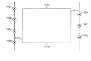
図1および図2を参照しつつ、本実施の形態にかかる座標検知装置を含むタッチパネル付きディスプレイ装置100の特徴的な構成および機能について説明する。図1は、実施の形態1にかかる座標検知装置を含むタッチパネル付きディスプレイ装置100を示す。また、図2は、図1に示したタッチパネル付きディスプレイ装置100をX軸方向から見た概略断面図である。
【0045】
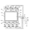
タッチパネル付きディスプレイ装置100は、座標入力面101と、座標入力面101に近接して配置された第1光学ユニット102a、第2光学ユニット102b、第3光学ユニット102c、第4光学ユニット102d、第5光学ユニット102e、第6光学ユニット102f、第7光学ユニット102gと、座標入力面101の外縁、すなわち4辺に設けられた反射部103a,103b,103c,103dと、第1方向検知部104a、第2方向検知部104b、第3方向検知部104c、第4方向検知部104d、第5方向検知部104e、第6方向検知部104f、第7方向検知部104gと、メイン制御部105と、インターフェース部106とを備えている。
【0046】
第1光学ユニット102a、第2光学ユニット102b、第3光学ユニット102c、第4光学ユニット102dは、いずれも座標入力面101の下辺101dに近接して配置されている。第5光学ユニット102e、第6光学ユニット102f、第7光学ユニット102gは、いずれも座標入力面101の上辺101bに近接して配置されている。このように、光学ユニット102a〜dと光学ユニットe〜gとは、座標入力面101の対向する辺にそれぞれ設けられている。
【0047】
下辺101d側に設けられた4つの光学ユニット102a〜dは、下辺101dに略平行な面外直線500上の異なる位置に配置されている。また、上辺101b側に設けられた3つの光学ユニット102e〜gは、上辺101bに略平行な面外直線502上の異なる位置に配置されている。
【0048】
また、反射部103a、反射部103b、反射部103c、および反射部103dはそれぞれ、座標入力面101の左辺101a、上辺101b、右辺101c、下辺101dに設けられている。
【0049】
座標入力面101は、矩形の面であって、ユーザがペンなどの指示棒や指によりタッチすることにより、タッチ点を入力するときに利用されるユーザインターフェースである。
【0050】
各光学ユニット102a〜gは、いずれも発光部と受光部とを有している。発光部は光を射出し、受光部は反射部103a〜dによって反射された光を受光する。なお、発光部および受光部については、後に図13を参照しつつ詳述する。
【0051】
各方向検知部104a〜gは、それぞれ対応する光学ユニット102a〜gが検知したタッチ点方向を検知する。なお、より具体的には、各方向検知部104a〜gは、それぞれ各光学ユニット102a〜gが検知した光の情報をアナログデータとして入力する。なお、アナログデータは、扇状に照射された光のうち、受光部の光を受光しなかった位置で本来受光されるはずの光の光軸、すなわちタッチ点方向を示す情報である。
【0052】
ここで、例えば第1光学ユニット102aと第1方向検知部104aの組み合わせは、本発明における方向検知手段を構成する。同様に、他の光学ユニット102b〜gと方向検知部104b〜gのそれぞれの組み合わせは、いずれも本発明における方向検知手段を構成する。
【0053】
メイン制御部105は、各方向検知部104a〜gからタッチ点方向を受け取り、タッチ点方向に基づいてタッチ点の座標であるタッチ点座標を算出する。メイン制御部105はさらに、光学ユニット102a〜gのうちから所定の光学ユニット102を選択し、選択した光学ユニットが検知したタッチ点方向に基づいて、タッチ点座標を算出する。メイン制御部105はまた、各光学ユニット102の駆動を制御する。ここで、メイン制御部105は、本発明の算出制御手段を構成する。
【0054】
インターフェース部106は、メイン制御部105からタッチ点座標を受け取り外部装置としてのパーソナルコンピュータ(PC)110に送る。
【0055】
なお、タッチパネル付きディスプレイ装置100の詳細な構成および機能については後述する。
【0056】
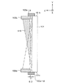
ここで、光学ユニット102a〜gと反射部103a〜dの位置関係を説明する。図2は、下辺101d側に配置された光学ユニット102a〜d、上辺101b側に配置された光学ユニット102e〜g、下辺101d側に配置された反射部103d、および上辺101b側に配置された反射部103bをX軸方向から見た図である。図2に示すように各光学ユニット102a〜gは、座標入力面101に接する位置に設けられている。そして、反射部103dおよび反射部103bは、それぞれ光学ユニット102a〜dおよび光学ユニット102e〜gに接する位置に設けられている。反射部103dおよび反射部103bは、さらに座標入力面101と離れた位置に設けられている。すなわち、反射部103bおよび反射部103dは、当該反射部と座標入力面101との間に隙間を設けて配置されている。
【0057】
例えば、第1光学ユニット102aの発光部から射出される光が通過する通過領域510と重なる位置に反射部103dが配置された場合、第1光学ユニット102aの発光部から射出された光は、対向する辺に到達できなくなる。すなわち、上辺101bに配置された反射部103bに到達できなくなる。これに対し、本実施の形態における反射部103dは、通過領域510に近接し、かつ重ならない位置に配置されている。従って、本実施の形態のように、対向する辺のそれぞれに光学ユニットを配置した場合であっても、各辺の発光部から射出された光はそれぞれ対向する辺に配置された反射部に確実に到達することができる。
【0058】
より具体的には、反射部103bおよび反射部103dは、通過領域510の座標入力面101に対する垂直方向、すなわちZ軸に沿った幅512に対応する間隔だけ、座標入力面101から隔たった位置に配置されている。
【0059】
対向する辺に複数の光学ユニット102を配置した場合、一方の辺側に配置された光学ユニット102がタッチ点方向を検知する際に、他方の辺側に配置された光学ユニット102が邪魔になるという不都合があった。しかし、本実施の形態におけるタッチパネル付きディスプレイ装置100のように、反射部103を座標入力面101から隔たった位置に設けることにより、いずれの光学ユニット102も、他方の光学ユニット102にタッチ点方向を検知するのを妨げられることなく確実にタッチ点方向を検知することができる。
【0060】
また、反射部103dは、反射部103dの位置における垂直方向、すなわちZ軸方向における、光学ユニット102eの発光部から射出された光の広がりの幅とほぼ等しい幅を有する。発光部から射出される光は、放射状に広がる。このため、第2光学ユニット102bの発光部から射出された光は、反射部103dの位置においては、幅518を有している。そこで、反射部103dは、光学ユニット102eの発光部から射出された光のZ軸方向の広がりの幅とほぼ等しい幅を有するように形成することが好ましい。
【0061】
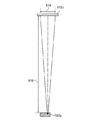
図3は、第1光学ユニット102aからの距離516が1800mm程度の位置に反射部103bを配置する場合の、反射部103bの幅と、反射部103bと光学ユニット102aとの距離との関係の一例を示している。光学ユニット102aからの距離516が1800mm程度の位置では、光学ユニット102aから射出された光の幅518は5mm程度である。そこで、光学ユニット102aから1800mmの位置に反射部103dを設ける場合には、反射部103dを1800mm以上の幅に設けるのが好ましい。
【0062】
なお、図2および図3を参照しつつ、下辺側に配置された光学ユニット102と、上辺側に配置された反射部103の構成について説明したが、上辺側に配置された光学ユニット103と下辺側に配置された反射部103の構成も同様である。
【0063】
また、座標入力面101の左辺101aおよび右辺101cには、光学ユニット102が設けられていないので、左辺101aおよび右辺101cにそれぞれ設けられた反射部103aおよび反射部103cは、図2および図3を参照しつつ説明したように、座標入力面101と隔たった位置にある必要はなく、反射部103aおよび反射部103cの配置は、座標入力面101に接する位置に設けられてもよく、また隔たった位置に設けられていてもよい。
【0064】
また、反射部103bおよび反射部103dのうち光学ユニット102と重なる位置のみが、101aと隔たった位置にあればよく、これ以外の位置における反射部103の設置位置は、限定されない。他の例としては、光学ユニットと重なる部分を切り欠いた反射部103bおよび反射部103dを、座標入力面に接する位置に配置してもよい。この場合も、近接する発光部121から射出された光は、反射部103bおよび反射部103dの切り欠き部分を通過して対向する辺側に配置された反射部に到達することができる。
【0065】
図4は、方向検知部104およびメイン制御部105がタッチ点座標を算出する原理を説明するための図である。本図を用いて、第1光学ユニット102aおよび第6光学ユニット102fが検知したタッチ点方向に基づいてタッチ点Tの座標を算出する場合について説明する。まず、座標入力面101の高さ、すなわち短辺の長さをH、座標入力面101の幅、すなわち長辺の長さをWとすると、第1光学ユニット102aとタッチ点Tとを通る直線500と第1光学ユニット102aと第6光学ユニット102fとを通る直線504とのなす角の角度θ1を算出する。すなわち、角度θ1は、第1光学ユニット102aが検知したタッチ点方向を示す。また、第6光学ユニット102fとタッチ点Tとを通る直線502と直線504とのなす角の角度をθ2を算出する。すなわち、角度θ2は、第6光学ユニット102fが検知したタッチ点方向を示す。さらに、角度θ1,θ2を以下の式に代入することによってタッチ点Tの座標(x,y)を算出する。
x=W×tanθ2/(tanθ1+tanθ2) …(1)
y=H−W×tanθ1×tanθ2/(tanθ1+tanθ2)…(2)
【0066】
なお、本図においては、下辺側に配置された光学ユニット102a〜dがタッチ点座標を算出する原理について説明したが、上辺側に配置された光学ユニット102e〜gがタッチ点座標を算出する方法は、下辺側に配置された光学ユニットa〜dがタッチ点座標を算出する方法と同様である。
【0067】
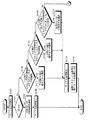
図5は、座標入力面101がタッチされたときの、タッチパネル付きディスプレイ装置100の処理を示すフローチャートである。ユーザがペンなどにより座標入力面101をタッチすると各光学ユニット102a〜gはタッチ点に対応して遮蔽された方向、すなわちタッチ点方向を検知する(ステップS100)。そして、メイン制御部105は、入力されたタッチ点の数を判断する(ステップS102)。
【0068】
ここで、メイン制御部105がタッチ点の数を判断する方法について説明する。メイン制御部105は、全ての光学ユニット102a〜gから受け取ったタッチ点方向を順次判断する。例えば、全ての光学ユニット102a〜gが、1つのタッチ点方向のみを検知した場合には、タッチ点は、1点のみであると判断することができるので、メイン制御部105は、全ての光学ユニット102a〜gが1つのタッチ点方向のみを検知した場合には、1つのタッチ点が入力されたと判断する。
【0069】
なお、他の例としては、メイン制御部105は、全て、すなわちn個の光学ユニットのうち、(n−1)個の光学ユニットが1つのタッチ点方向のみを検知した場合に、1つのタッチ点が入力されたと判断してもよい。具体的には、全ての光学ユニット102a〜g、すなわち6つの光学ユニット102a〜gのうち、5つの光学ユニットが1つのタッチ点方向のみを検知した場合である。
【0070】
また、理論的には、少なくとも2つの光学ユニット102が1つのタッチ点方向のみを検知した場合には、すべての光学ユニット102a〜gのタッチ点方向を考慮するまでもなく、入力されたタッチ点は1点のみであると判断することができる。そこで、さらに他の例としては、メイン制御部105は、少なくとも2つの光学ユニット102から1つのタッチ点方向を検知した場合に1つのタッチ点が入力されたと判断してもよい。
【0071】
また、メイン制御部105は、少なくとも1つの光学ユニット102が、互いに隔たった2つのタッチ点座標をほぼ同時に検知した場合に、タッチ点は、2点であると判断する。
【0072】
再び、図5を参照しつつ、タッチパネル付きディスプレイ装置100の処理について説明する。1つのタッチ点のみが入力された場合には(ステップS102,Yes)、メイン制御部105は、全ての光学ユニット102a〜gのうちから任意の2つの光学ユニット102を選択する(ステップS104)。そして、メイン制御部105は、選択した2つの光学ユニット102が検知したタッチ点方向に基づいて、前述の式(1)および式(2)によりタッチ点座標を算出する(ステップS106)。
【0073】
タッチ点が1点のみの場合には、タッチ点の座標を正確に算出できないという問題が生じないので、いずれの2つの光学ユニット102が検知したタッチ点方向に基づいてタッチ点座標を算出した場合であっても誤差の少ない値を算出することができるので、いずれの2つの光学ユニット102を選択してもよい。
【0074】
このように、タッチ点座標を算出するときに、2つの光学ユニット102が検知したタッチ点方向に基づくタッチ点座標の算出しか行わないので、演算処理が簡単になり、処理に対する装置の負担を軽減することができる。すなわち、他の光学ユニット102が検知したタッチ点方向に基づくタッチ点座標の算出処理を省略することができる。
【0075】
なお、このとき選択すべき2つの光学ユニット102は、予め設定しておいてもよい。
【0076】
一方、下辺側の光学ユニット102のいずれかが、2つのタッチ点方向を検知した場合には(ステップS102,No)、メイン制御部105は、下辺側に配置される他の光学ユニットが検知したタッチ点方向を判断する。メイン制御部105は、下辺側に配置された3つ以上の光学ユニットが2つのタッチ点方向を検知したと判断した場合には(ステップS110,Yes)、下辺側に配置されている光学ユニットのうち2つのタッチ点方向を検知した任意の2つの光学ユニットの組み合わせを2つ選択し(ステップS112)、各組み合わせから2つのタッチ点座標を算出する(ステップS114)。
【0077】
図7を参照しつつ、下辺側に配置された光学ユニットの2つの組み合わせからタッチ点座標を算出する処理について説明する。図7に示すように、点Pおよび点Qが同時にタッチされた場合を示している。第1光学ユニット102a、第2光学ユニット102b、および第3光学ユニット102cがこれら2点に対応するタッチ点方向を検知した場合、メイン制御部105は、例えば、第1光学ユニット102aおよび第2光学ユニット102bがそれぞれ点Pおよび点Qに対応して検知したタッチ点方向に基づいて、式(1)および式(2)からタッチ点座標を算出する。ただし、式(1)および式(2)を利用して座標を算出した場合、実際のタッチ点P,Qのほかに、仮想的な点R,Sの座標が算出されてしまう。従って、これら4つの座標から、実際のタッチ点P,Qを選択するのが困難である。
【0078】
しかし、本実施の形態においては、さらに、第1光学ユニット102aおよび第3光学ユニット102cがそれぞれ点Pおよび点Qに対応して検知したタッチ点方向に基づいて、さらに仮想的な点を含む4つの座標を算出し、2つの組み合わせのいずれからも算出されるタッチ点座標を真のタッチ点座標と決定することができる。このように、少なくとも3つの光学ユニット102が検知したタッチ点方向を利用することによって、仮想的なタッチ点座標および真のタッチ点座標のうちから、容易に真のタッチ点座標を決定することができる。
【0079】
なお、本実施の形態においては、3つの光学ユニットが検知したタッチ点方向の組み合わせに基づいて2つのタッチ点座標を算出したが、他の例としては、4つの方向検知部の2つの組み合わせから2つのタッチ点座標を算出してもよく、いずれの方向検知部を選択するか、およびいずれの方向検知部同士を組み合わせるかは特に実施の形態に限定されるものではない。
【0080】
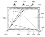
ここで、図8および図9を参照しつつ、同時に2つのタッチ点が入力された場合の、メイン制御部105の処理について詳述する。図8に示すように、点Bが、第1光学ユニット102aと点Aとを結ぶ直線上の点である場合、点Bは、点Aにより形成される影の中に含まれてしまう。このため、光学ユニット102aでは、この場合には、2点が入力されているにもかかわらず、1つのタッチ点方向のみしか検知することができない。従って、従来のように2つの光学ユニットしか備えていない場合には、正確に点Aおよび点Bのタッチ点方向を検知することができなかった。
【0081】
これに対して、本実施の形態のタッチパネル付きディスプレイ装置100は、下辺側に4つの光学ユニット102a〜dを備えているので、例えば、第1光学ユニット102aにおいて2つのタッチ点方向を分離して検知できない場合には、第2光学ユニット102bおよび第4光学ユニット102dが検知した2つのタッチ点方向に基づいてタッチ点座標を算出することができる。
【0082】
このように、複数の光学ユニット102が2つのタッチ点を検知するので、2つのタッチ点の位置に応じて、最も信頼性の高いタッチ点方向を検知する光学ユニットを選択するよう設定してもよい。具体的には、タッチ点の位置に応じて、選択すべき光学ユニットの優先順位を予め定めてもよい。
【0083】
さらに、本実施の形態においては、上辺側にも3つの光学ユニット102e〜gを備えているので、下辺側の4つの光学ユニット102a〜dのうち1以下の光学ユニットのみしか2つのタッチ点方向を検知できない場合には、上辺側の2の光学ユニットが検知した2つのタッチ点方向に基づいて、2つのタッチ点座標を算出することができる。
【0084】
図9は、手をついてタッチペンにより入力されたときのタッチ点の様子を示している。タッチペンに対応するタッチ領域Mと座標入力面101についた手に対応するタッチ領域Nの位置が近く、かつ互いの大きさが極端に異なっている。このため、図9に示すように、2つの光学ユニット420a,420bの間にミラー400を設けた場合であっても、ペンに対応するタッチ領域Mは、手に対応するタッチ領域Nに隠れてしまうので、タッチ領域Mおよびタッチ領域Nの座標を正確に算出できない。この場合には、ミラー400の位置を変更することにより、2つの領域に対するタッチ領域方向を検知することも可能である。しかし、座標入力面101全面におけるすべての2点を検知することはできない。
【0085】
これに対し、本実施の形態のタッチパネル付きディスプレイ装置100は、下辺側および上辺側にそれぞれ光学ユニット102が設けられているので、図9のように近接する位置の2つのタッチ点や、極端に大きさの異なる2つのタッチ点を精度よく分離して検知することができる。具体的には、図9に示すタッチ点Mおよびタッチ点Nが入力された場合には下辺側の光学ユニット102a〜dのうち1の光学ユニットしか2つのタッチ点方向を検知できない場合や、いずれの光学ユニットも2つのタッチ点方向を検知できない場合であっても、上辺の光学ユニットのうち2つの光学ユニットが2つのタッチ点方向を検知することができる。
【0086】
再び説明を図5に戻す。2つのタッチ点が入力され(ステップS102,No)、かつ下辺101d側の3つ以上の光学ユニットが2つのタッチ点方向を検知しない場合(ステップS110,No)、すなわち、タッチ点が2つ存在すると判断した光学ユニットが2つ以下であった場合には、上辺101aに対向する辺側に配置されている複数の光学ユニットが検知したタッチ点方向の個数を判断する。
【0087】
他方の辺に配置されている光学ユニットのうち3つ以上の光学ユニットが2つのタッチ点方向を検知した場合には(ステップS120,Yes)、2つのタッチ点方向を検知した光学ユニットの2組の組み合わせを選択する(ステップS122)。
【0088】
そして、ステップS114に進み、各光学ユニットの組み合わせから算出されるタッチ点座標から真のタッチ点座標を算出する(ステップS114,116)。
【0089】
図10は、同時にタッチされた点Pおよび点Qと、これらを異なるタッチ点方向として検知した上辺101b側の3つの光学ユニット102e〜gを示している。この場合、例えば、第5光学ユニット102eおよび第6光学ユニット102fがそれぞれ点Pおよび点Qに対応して検知したタッチ点方向に基づいて4つのタッチ点座標を算出する。さらに第5光学ユニット102eおよび第7光学ユニット102gがそれぞれ点Pおよび点Qに対応して検知したタッチ点方向に基づいて4つのタッチ点座標を算出する。そして、2つの組み合わせのいずれからも算出されるタッチ点座標を真のタッチ点座標と決定する。
【0090】
再び、説明を図5に戻す。2つのタッチ点が入力され(ステップS102,No)、かつ下辺101d側および上辺101b側でともに3つ以上の光学ユニットが2つのタッチ点方向を検知せず(ステップS110,No、ステップS120,No)、上辺101b側に配置された2つの光学ユニットおよび下辺101d側に配置された2つの光学ユニットが2つのタッチ点方向を検知した場合には(ステップS130,Yes)、下辺101d側に配置された2つの光学ユニットが検知したタッチ点方向に基づいてタッチ点座標を算出し、かつ上辺101b側の2つの光学ユニットが検知したタッチ点方向に基づいてタッチ点座標を算出する(ステップS132)。そして、ステップS114に進み、各組み合わせから算出されたタッチ点座標のうち重複する2つのタッチ点座標を、真のタッチ点座標として決定する(ステップS114,ステップS116)。
【0091】
図11は、同時にタッチされた点Pおよび点Qと、これらを異なるタッチ点方向として検知した上辺101b側の2つの光学ユニット102f,102gと、下辺101d側の2つの光学ユニット102b,102cを示している。この場合、第2光学ユニット102bと第3光学ユニット102cがそれぞれ点Pおよび点Qに対応して検知したタッチ点方向に基づいて4つの仮想座標を含む4つのタッチ点座標を算出する。さらに、第6光学ユニット102fおよび第7光学ユニット102gがそれぞれ点Pおよび点Qに対応して検知したタッチ点方向に基づいて仮想座標を含む4つのタッチ点座標を算出する。そして、2つの組み合わせのいずれからも算出されるタッチ点座標を真のタッチ点座標と決定する。
【0092】
このように、座標入力面101の上辺101b側および下辺101d側のいずれにも光学ユニットが配置されているので、両辺に配置されている光学ユニットが検知したタッチ点方向に基づいて、タッチ点座標を算出することができる。
なお、ここで、座標入力面101の上辺および下辺は、本発明の第1の辺および第2の辺を構成する。
【0093】
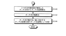
再び、説明を図5および図6に戻す。2つのタッチ点が入力され(ステップS102,No)、かつ上辺側および下辺側の少なくとも1辺側で2つの光学ユニットのみが2つのタッチ点方向を検知し、かつ他方の辺で、1つの光学ユニットのみがタッチ点方向を検知した場合、および上辺側および下辺側の少なくとも1辺側で2つの光学ユニットのみが2つのタッチ点方向を検知し、かつ他方の辺で、いずれの光学ユニットも2つのタッチ点方向を検知しない場合(ステップS110,No、ステップS120,No、ステップS130,No)、2つの光学ユニットが検知した2つのタッチ点方向に基づいて、4つのタッチ点座標を算出する(ステップS140)。なお、タッチ点座標として、タッチ点の中心の座標を算出することとしている。
【0094】
さらに2つのタッチ点の幅を算出し(ステップS142)、タッチ点の幅が近い値を示すタッチ点に対するタッチ点座標を、真のタッチ領域に対応する座標と決定する(ステップS144)。以上で、タッチパネル付きディスプレイ装置100の処理は終了する。
【0095】
図12は、タッチ点P、Qと、第1光学ユニット102aおよび第2光学ユニット102bが検知するタッチ点方向との関係を示す模式図である。例えば、座標入力面101に手をついて、タッチペンなどにより入力した場合には、図12に示すように、タッチペンが接触したタッチ点Pと、ついた手が接触したタッチ点Qとが入力される。この場合、2つの光学ユニット102a,102bがそれぞれ検知したタッチ点方向に基づいて、タッチ点P,Qに加えて、仮想的なタッチ点K,Lのタッチ点座標が算出される。
【0096】
そこで、光学ユニット102aは、さらにタッチ点Pに対応して角度θ3の幅の連続したタッチ点方向を検知する。光学ユニット102aは、またタッチ点Qに対応して角度θ4の幅の連続したタッチ領域方向を検知する。一方、光学ユニット102bは、タッチ点Pに対応して角度θ5の幅の連続したタッチ点方向を検知し、かつタッチ点Qに対応して角度θ6の幅の連続したタッチ点方向を検知する。
【0097】
図12に示されているように、真のタッチ点(P,Q)は、仮想的なタッチ点(K,L)に比べて円形に近い領域であるのが一般的である。そこで、メイン制御部105は、光学ユニット102aおよび光学ユニット102bが検知した連続したタッチ領域方向の角度が近いタッチ領域を真のタッチ領域として決定する。
【0098】
なお、本実施の形態においては、メイン制御部105は、下辺101d側に配置された第1光学ユニット102aが検知したタッチ点方向から順に第2光学ユニット102b、第3光学ユニット102c、第4光学ユニット102d、第5光学ユニット102e、第6光学ユニット102f、および第7光学ユニット102gの順でタッチ点方向を判断するが、他の例としては、上辺101b側に配置された光学ユニット102が検知したタッチ点方向から順に判断してもよい。
【0099】
このように、2つのタッチ点が入力され、2つの光学ユニットが検知したタッチ点方向しか得られない場合には、タッチ点方向の角度範囲に基づいて2つのタッチ点座標を決定することができる。
【0100】
図13は、光学ユニット102の詳細な構成を示している。図13(A)は、光学ユニット102を、座標入力面101に平行な面内で照射光の進行方向に直交する向き、すなわちx軸方向から見た状態を示している。また、図13(B)は、光学ユニット102を照射光の進行方向、すなわちy軸方向から見た状態を示している。
【0101】
光学ユニット102は、発光部121と、反射部103a〜dからの反射光を受光する受光部125と、光の方向を制御するハーフミラー124とを有している。さらに、発光部121は、光源122から射出された光を扇状に拡散するレンズ123a〜cとを含んでいる。また、受光部125は、ハーフミラー124を通過した光を集光する集光レンズ126と、フォトセンサなどの受光素子が複数個連なったラインセンサ127とを含んでいる。
【0102】
反射光は、ラインセンサ127の異なる位置に配置された受光素子に到達するので、反射光を検知した受光素子が配置された位置に基づいて、遮蔽方向を検出することができる。
【0103】
図14は、受光部125がタッチ点方向を検知する原理を説明するための模式図である。座標入力面101上のある位置Uに指が接触すると照射光が遮断され、その方向に対応するラインセンサ127上の対応する点に反射光が到達しなくなる。すなわち、図14に示すように座標入力面101上の位置Uに光を遮る指が接触すると、ここを通過する光が遮られ、ラインセンサ127上では位置Dにおいて受光強度の小さい領域、すなわち暗点が生じる。この暗点の位置Dは、遮蔽方向(位置U)と一対一に対応する。したがって、ラインセンサ127が検知した暗点に基づいて遮蔽方向を検知することができる。
【0104】
なお、ラインセンサ127における受光強度が均一になるように、シリンドリカルレンズ123cの後段もしくはラインセンサ127の前段に濃淡のついたフィルタを設けてもよい。これにより、ラインセンサ127の各素子に対して方向に依存した閾値を設定する必要が無くなり、制御が容易となる。
【0105】
メイン制御部105は、暗点Dに基づいた遮蔽方向から座標Aの位置を算出する。暗点Dは指示棒や指等を光軸から測定した検出角度と1対1に対応しており、ラインセンサ127上の暗点の位置Dから検出角度を算出することができる。受光レンズ126からラインセンサ127までの距離をfすると、検出角度θdは、暗点の位置Dの関数として式(3)で与えられる。
θd=arctan(D/f) ・・・(3)
【0106】
なお、厳密には、受光レンズ126による光の屈折により、式(3)の関係は成立しない。しかし、検出角度θdとD/fとの関係は一意に決まるので、ここでは、簡単のため式(3)が成立するものとして取り扱う。なお、光軸とは受光レンズ126の光軸を示す。
【0107】
以上のようにして算出された角度、すなわちタッチ点方向θdを、前述の式(1)および式(2)に代入することにより、タッチ点Uのタッチ点座標を算出することができる。
【0108】
次に、図15を参照しつつ、タッチパネル付きディスプレイ装置100の詳細なハードウェア構成について説明する。なお、本図においては、便宜的に1つの光学ユニット102および1つの方向検知部104のみを示しているが、タッチパネル付きディスプレイ装置100に含まれる全ての光学ユニット102a〜gおよび全ての方向検知部104a〜gは、本図に示す光学ユニット102および方向検知部104と同一の構成および機能である。
【0109】
光学ユニット102は、LD122を含む発光ユニット200と、ラインセンサ127を含む受光ユニット210とを有している。ラインセンサ127は、方向検知部104の画像処理LSI(後述)によって駆動される。
【0110】
方向検知部104は、方向検知部104全体を制御するCPU401と、タッチ点方向を検知するプログラムを格納するROM402と、ワークメモリとして使用されるRAM403と、画像処理などを行う画像処理LSI404と、光学ユニット102からのデータを格納するデータ格納メモリ405と、シェーディング補正を行う基準となるデータを格納するシェーディングメモリ406とを有している。
【0111】
メイン制御部105は、メイン制御部105全体を制御するCPU501と、システムを制御するプログラムを格納するROM502と、ワークメモリとして使用されるRAM503と、インターフェース部106を制御するインターフェース制御部504とを有している。
【0112】
なお、本実施の形態においては、ワークメモリとして使用されるRAM503、および光学ユニット102からのデータを格納するデータ格納メモリ405をそれぞれ別個に設けているが、これらは、1つのメモリ内に設けられてもよい。この場合、1つのメモリ内の分割された各領域が、ワークメモリおよび光学ユニット102からのデータを格納するためのメモリとして機能する。
【0113】
複数の光学ユニットが独立して駆動すると、座標入力面101にタッチ点が入力された場合に、一の光学ユニットにおいてはタッチ点方向が検知されるが、他の光学ユニットにおいてはタッチ点が検知されないといった不具合が生じてしまう。このため、メイン制御部105のCPU501は、トリガを生成し、生成したトリガに応じてLD122を駆動させることにより、各LDの発光のタイミングを同一にする。また、それぞれの方向検知部104の画像処理LSI404にトリガ信号520を送る。そして、画像処理LSI404は、トリガ信号520に応じてラインセンサ127を駆動させる。
【0114】
これにより、複数の光学ユニット102a〜gは、全て同期して駆動されるので、全ての光学ユニット102a〜gが、同一のタイミングで、タッチ点方向を検知することができる。すなわち、メイン制御部105の制御により、発光部121は、同一のタイミングで光を照射し、受光部125は、同一のタイミングで反射光を受光する、すなわち、タッチ点方向を検知する。
【0115】
図16は、各光学ユニット102a〜dの発光部121および受光部125の発光および受光のタイミングを示している。図16(A)は、上辺側の受光部125の受光タイミングを示している。図16(B)は、上辺側の発光部121の発光タイミングを示している。図16(C)は、下辺側の受光部125の受光タイミングを示している。図16(D)は、下辺側の発光部121の発光タイミングを示している。
【0116】
上辺側の発光部121の発光タイミングと、上辺側の受光部125の受光タイミングとは一致する。また、下辺側の発光部121の発光タイミングと、下辺側の受光部125の受光タイミングとは一致する。
【0117】
さらに、上辺側の発光部121と、下辺側の発光部121とは、交互に発光する。すなわち、上辺側の発光部121が発光しているときは、下辺側の発光部121は消灯し、下辺側の発光部121が発光しているときは、上辺側の発光部121は消灯している。また、これに対応して、上辺側の受光部125および下辺側の受光部125も交互のタイミングで受光する。
【0118】
なお、上辺側の複数の光学ユニット102の発光部121および受光部125は、いずれも同一のタイミングで発光および受光する。また、下辺側の複数の光学ユニット102の発光部121および受光部125は、いずれも同一のタイミングで発光および受光する。
【0119】
光学ユニット102から射出される光は、座標入力面101に平行に拡散されている。光学ユニット102は、座標入力面101の対向する辺に配置されているので、一方の辺の光学ユニットの発光部から射出された光が、他方の辺に配置された光学ユニットの受光部に入光する。従って、例えば上辺の発光部の発光のタイミングと下辺の受光部の受光のタイミングとが一致した場合には、タッチ点を誤検出してしまう。従って、図16を参照しつつ説明したように、上辺側の光学ユニットの発光部および受光部の発光および受光のタイミングと、下辺側の光学ユニットの発光部および受光部の発光および受光のタイミングとを逆にすることにより、誤検出を防止することができる。
【0120】
また、方向検知部104のCPU401とメイン制御部105のCPU501とはシリアル通信を行っており、検知を開始させる旨を示す検知開始指示や、検知したタッチ点方向(510)の送受信を行う。
【0121】
方向検知部104のCPU401とメイン制御部105のCPU501は、このシリアル通信により、検出開始指示、ディップ検出位置の送受信を行っている。
【0122】
なお、本実施の形態においては、シリアルインターフェースを用いているが、他の例としては、装置内部での通信なので、専用のインターフェースを用いてもよい。
【0123】
以上、本発明を実施の形態を用いて説明したが、上記実施の形態に多様な変更または改良を加えることができる。
【0124】
そうした第1の変更例としては、本実施の形態においては、光学ユニット102a〜gは、座標入力面101の上辺101b側と下辺101d側にそれぞれ設けられていたが、これにかえて、光学ユニット102a〜gを座標入力面101の左辺101a側と下辺101c側にそれぞれ設けられていてもよい。図17は、第1の変更例に係る光学ユニット102a〜gを示している。
【0125】
このように、座標入力面101の左辺101a側と右辺101c側に光学ユニット102a〜gを配置した場合であっても、実施の形態において説明した上辺101b側と下辺101d側に光学ユニットを配置した場合と同様に、2つのタッチ点が同時に入力された場合であっても、精度よく2つのタッチ点のタッチ点座標を算出することができる。
【0126】
第2の変更例としては、本実施の形態における光学ユニット102a〜gは、上辺101bおよび下辺101dすなわち対向する2辺にそれぞれ設けられていたが、これにかえて、光学ユニット102a〜gを隣接する2辺に配置してもよい。図18は、第2の変更例にかかる光学ユニット102a〜gを示している。
【0127】
このように、座標入力面101の右辺101c側と下辺101d側に光学ユニット102a〜gを配置した場合であっても、実施の形態において説明した上辺101b側と下辺101d側に光学ユニットを配置した場合と同様に、2つのタッチ点が同時に入力された場合であっても、精度よく2つのタッチ点のタッチ点座標を算出することができる。
【0128】
第3の変更例としては、本実施の形態におけるタッチパネル付きディスプレイ装置100は、第1〜第7光学ユニット102a〜gを備えていたが、光学ユニットの数はこれに限定されるものではない。上辺101bに3つの光学ユニットを配置したが、上辺101bに配置する光学ユニットの数はこれに限定されない。また、下辺101dに4つの光学ユニットを配置したが、下辺101dに配置する光学ユニットの数はこれに限定されない。このように、光学ユニットの数およひ各辺に配置する光学ユニットの個数比は、実施の形態に限定されない。
【0129】
第4の変更例としては、本実施の形態におけるタッチパネル付きディスプレイ装置100の光学ユニット102a〜gは、各辺においてほぼ等間隔に配置されていたが、各光学ユニット102の位置は、これに限定されるものではない。例えば、タッチされる頻度が高いタッチ領域の位置などに基づいて、任意に変更してもよい。
【0130】
【発明の効果】
以上説明したように、請求項1にかかる発明によれば、一方の辺の方向検知手段が検知したタッチ点方向に基づいて、正確にタッチ点座標を算出できない場合であっても、他方の辺の方向検知手段が検知したタッチ点方向に基づいてタッチ点座標を算出することができる。従って、より正確にタッチ点座標を算出することができる。また、一方の辺の方向検知手段が検知したタッチ点方向と、他方の辺の方向検知手段が検知したタッチ点方向との両方に基づいて、正確にタッチ点座標を算出することができるという効果を奏する。
【0131】
さらに、第1の辺と第2の辺の両方に方向検知手段を配置することができるので、各方向検知手段の配置位置の自由度が増加し、より適切な位置に各方向検知手段を配置することができるという効果を奏する。
【0132】
また、請求項2にかかる発明によれば、一方の辺の方向検知手段が検知したタッチ点方向に基づいて、正確にタッチ点座標を算出できない場合であっても、他方の方向検知手段が検知したタッチ点方向に基づいて正確にタッチ点座標を算出することができる。また、一方の辺の方向検知手段が検知したタッチ点方向と、他方の辺の方向検知手段が検知したタッチ点方向との両方に基づいて、正確にタッチ点座標を算出することができるという効果を奏する。
【0133】
また、請求項3にかかる発明によれば、一方の辺の方向検知手段が検知したタッチ点方向に基づいて、正確にタッチ点座標を算出できない場合であっても、他方の方向検知手段が検知したタッチ点方向に基づいて正確にタッチ点座標を算出することができる。または、一方の辺の方向検知手段が検知したタッチ点方向と、他方の辺の方向検知手段が検知したタッチ点方向との両方に基づいて、正確にタッチ点座標を算出することができるという効果を奏する。
【0134】
また、請求項4にかかる発明によれば、他方の方向検知手段の方向検知に起因した誤検出を防ぐことができる。従って、正確にタッチ点方向を検知することができるという効果を奏する。
【0135】
また、請求項5にかかる発明によれば、各受光手段が異なる辺に配置された発光手段により射出された光の反射光を過って受光するのを防ぐことができる。従って、正確にタッチ点方向を検知することができるという効果を奏する。
【0136】
また、請求項6にかかる発明によれば、異なる辺に配置される発光手段は、それぞれ異なるタイミング、すなわち交互に光を射出するので、このタイミングにあわせて、同一の辺に配置された受光手段が射出された光の反射光を受光することにより、当該発光手段と異なる辺に配置された受光手段が当該発光手段により射出された光の反射光を過って受光するのを防ぐことができる。従って、正確にタッチ点方向を検知することができるという効果を奏する。
【0137】
また、請求項7にかかる発明によれば、各方向検知手段がタッチ点方向を検知するタイミングの違いにより、各方向検知手段が異なるタッチ点に対するタッチ点方向を検知するのを避けることができる。このように、複数の方向検知手段が同一のタイミングで、タッチ点方向を検知するので、タッチ点方向に基づいて、正確にタッチ点座標を算出することができるという効果を奏する。
【0138】
また、請求項8にかかる発明によれば、同一の辺に配置された受光手段は、いずれも同一のタイミングで反射光を受光するので、各受光手段が、タッチ点方向を検知するタイミングの違いにより、異なるタッチ点方向を検知するのを避けることができるという効果を奏する。
【0139】
また、請求項9にかかる発明によれば、同一の辺に配置された発光手段は、いずれも同一のタイミングで光を射出するので、光を射出するタイミングの違いにより、異なるタッチ点方向を検知するのを避けることができるという効果を奏する。
【0140】
また、請求項10にかかる発明によれば、座標入力面と反射手段との間の隙間に光学ユニットを配置することにより、座標入力装置全体を大型化することなく、2辺に光学ユニットを配置することができるという効果を奏する。
【0141】
また、請求項11にかかる発明によれば、反射手段と座標入力面との間に、通過領域に相当する隙間が設けられているので、反射手段により光が遮られるのを避けることができるという効果を奏する。
【0142】
また、請求項12にかかる発明によれば、反射手段は、光の広がりの幅とほぼ等しい幅に設けられているので、一方の辺の光学ユニットから射出された光を他方の辺の光学ユニットが受光することを避けることができるという効果を奏する。
【0143】
また、請求項13にかかる発明によれば、2つのタッチ点方向の異なる2つの組み合わせそれぞれから、タッチ点座標を算出するので、真のタッチ点座標に加えて仮想的なタッチ点座標が算出された場合であっても、この中から、正確に真のタッチ点座標を算出することができるという効果を奏する。
【0144】
また、請求項14にかかる発明によれば、一方の辺側の方向検知手段が検知したタッチ点方向に基づいて、同時に入力されたタッチ点のタッチ点座標を正確に算出できない場合には、他方の辺の方向検知手段が検知したタッチ点方向をさらに利用して、タッチ点座標を算出することにより、正確なタッチ点座標を算出することができるという効果を奏する。
【0145】
また、請求項15にかかる発明によれば、算出制御手段は、タッチ点方向に基づいて、タッチ点方向の角度範囲のそれぞれに基づいて、タッチ点の所定の方向における幅をさらに算出することができるので、この幅の値に基づいて、真のタッチ点座標を決定することができる。従って、正確なタッチ点座標を算出することができるという効果を奏する。
【0146】
また、請求項16にかかる発明によれば、方向検知手段が検知したタッチ点方向に基づいて、正確なタッチ点座標を算出できない場合には、タッチ点方向の角度範囲のそれぞれに基づいて、タッチ点の幅を算出することができるので、タッチ点の幅に基づいて、真のタッチ点座標を決定することができるという効果を奏する。
【図面の簡単な説明】
【図1】タッチパネル付きディスプレイ装置100を示す図である。
【図2】光学ユニットと反射部との位置関係を示す模式図である。
【図3】光学ユニットと反射部との距離の関係の一例を示す図である。
【図4】方向検知部104およびメイン制御部105がタッチ点座標を算出する原理を説明するための図である。
【図5】座標入力面がタッチされたときの、タッチパネル付きディスプレイ装置の処理を示すフローチャートである。
【図6】座標入力面がタッチされたときの、タッチパネル付きディスプレイ装置の処理を示すフローチャートである。
【図7】下辺側に配置された光学ユニットの2つの組み合わせからタッチ点座標を算出する処理について説明するための図である。
【図8】2つのタッチ点AおよびBの位置を示す図である。
【図9】利用者が手をついてタッチペンにより座標入力面をタッチした場合のタッチ点NおよびMの位置を示す図である。
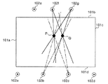
【図10】同時にタッチされた点Pおよび点Qと、これらを異なるタッチ点方向として検知した光学ユニットを示す図である。
【図11】同時にタッチされた点Pおよび点Qと、これらを異なるタッチ点方向として検知した光学ユニットを示す図である。
【図12】タッチされた点Pおよび点Qと、第1光学ユニットと第2光学ユニットが検知するタッチ点方向との関係を示す模式図である。
【図13】光学ユニットの詳細な構成を示す図である。
【図14】受光部125がタッチ点方向を検出する原理を説明するための模式図である。
【図15】タッチパネル付きディスプレイ装置の詳細なハードウェア構成を示す図である。
【図16】各光学ユニットの発光部の発光のタイミング、および受光部の受光のタイミングを示す図である。
【図17】第1の変更例に係る光学ユニットの配置を示す図である。
【図18】第2の変更例に係る光学ユニットの配置を示す図である。
【図19】従来技術にかかる座標検知装置の一例を示す図である。
【符号の説明】
100 タッチパネル付きディスプレイ装置
101 座標入力面
102a〜g 光学ユニット
103a〜d 反射部
104a〜g 方向検知部
105 メイン制御部
106 インターフェース部
121 発光部
122 光源
123 レンズ
124 ハーフミラー
125 受光部
126 集光レンズ
127 ラインセンサ
200 発光ユニット
210 受光ユニット
400 ミラー
405 データ格納メモリ
406 シェーディングメモリ
504 インターフェース制御部[0001]
TECHNICAL FIELD OF THE INVENTION
The present invention relates to a coordinate detection device that detects coordinates of a touch point input on a coordinate input surface.
[0002]
[Prior art]
At present, a display device with a touch panel, which integrates a display screen and a coordinate input device and can control an image displayed on the display screen while touching the display screen, is becoming widespread. Also, a relatively large-sized display device with a touch panel is known, which is intended for use in school lessons, presentations at companies, and the like.
[0003]
An optical coordinate input device is known. The optical coordinate input device calculates the coordinates of the position by detecting the direction of the position input on the coordinate input surface from two directions. FIG. 19 shows an example of a conventional optical coordinate detecting device. The
[0004]
Each of the
[0005]
However, for example, as shown in FIG. 19, when points A and B in a positional relationship such that the right
[0006]
As a method for solving such a problem, a mirror that can be rotated by 360 ° is provided, and when one optical unit detects only one direction in spite of two touches, only one point is detected. There is known a technique of irradiating a mirror with light on the side of an optical unit not to be rotated, rotating the mirror, and detecting two points from a rotation angle (for example, see Patent Document 1).
[0007]
[Patent Document 1]
JP-A-2002-55770 (page 4-7, FIG. 1)
[0008]
[Problems to be solved by the invention]
However, when two points are extremely different in size or when two points are close to each other, for example, when the user is writing with the hand on the coordinate input surface, the two points are separated and detected. The problem remains that it is difficult to do so.
[0009]
The present invention has been made in view of the above, and an object of the present invention is to provide a coordinate detection device that can accurately calculate the coordinates of a touch point input on a coordinate input surface.
[0010]
[Means for Solving the Problems]
In order to achieve the above object, an invention according to
[0011]
According to the first aspect of the present invention, since the direction detecting means is provided on each of the first side and the second side, it is possible to accurately detect the direction of the touch point detected by the direction detecting means on one side. Even when the coordinates of the touch point cannot be calculated, the coordinates of the touch point can be calculated based on the direction of the touch point detected by the direction detecting means on the other side. Therefore, the coordinates of the touch point can be calculated more accurately. Further, the touch point coordinates can be accurately calculated based on both the touch point direction detected by the direction detecting means on one side and the touch point direction detected by the direction detecting means on the other side.
[0012]
Further, since the direction detecting means can be arranged on both the first side and the second side, the degree of freedom of the arrangement position of each direction detecting means is increased, and each direction detecting means is arranged at a more appropriate position. can do.
[0013]
The invention according to claim 2 is the coordinate detecting device according to
[0014]
According to the second aspect of the present invention, since the direction detecting means is disposed on each of the two opposing sides, the touch point coordinates can be accurately calculated based on the touch point direction detected by the direction detecting means on one side. Even if it is impossible, the touch point coordinates can be accurately calculated based on the touch point direction detected by the other direction detecting means. Further, the touch point coordinates can be accurately calculated based on both the touch point direction detected by the direction detecting means on one side and the touch point direction detected by the direction detecting means on the other side.
[0015]
The invention according to claim 3 is the coordinate detecting device according to
[0016]
According to the third aspect of the present invention, since the direction detecting means is disposed on each of the two sides that are in contact with each other, the touch point coordinates can be accurately calculated based on the touch point direction detected by the direction detecting means on one side. Even if it is impossible, the touch point coordinates can be accurately calculated based on the touch point direction detected by the other direction detecting means. Alternatively, the touch point coordinates can be accurately calculated based on both the touch point direction detected by the direction detecting means on one side and the touch point direction detected by the direction detecting means on the other side.
[0017]
The invention according to claim 4 is the coordinate detecting device according to any one of
[0018]
According to the fourth aspect of the present invention, the first direction detecting means and the second direction detecting means arranged on different sides detect the touch point directions at different timings, that is, alternately, so that the other direction is detected. Erroneous detection due to the direction detection of the means can be prevented. Therefore, the touch point direction can be accurately detected.
[0019]
The invention according to claim 5 is the coordinate detection device according to claim 4, wherein the direction detection means emits light that spreads in a fan shape along a plane parallel to the coordinate input surface. Light receiving means for receiving reflected light from a reflecting means for reflecting light passing through the coordinate input surface, the light receiving means disposed in proximity to the first side, and the second side And receiving the reflected light at different timings.
[0020]
According to the fifth aspect of the present invention, the light receiving means arranged on different sides receive reflected light at different timings, that is, alternately, so that each light receiving means is emitted by the light emitting means arranged on a different side. It is possible to prevent the reflected light of light from being received. Therefore, the touch point direction can be accurately detected.
[0021]
The invention according to claim 6 is the coordinate detecting device according to claim 4 or 5, wherein the direction detecting means emits light that spreads in a fan shape along a plane parallel to the coordinate input surface. Means, and light receiving means for receiving reflected light from a reflecting means for reflecting light passing through the coordinate input surface, wherein the light emitting means is arranged in proximity to the first side; And emitting light at different timings from the light emitting means disposed in the vicinity of the side.
[0022]
According to the sixth aspect of the present invention, the light emitting means arranged on different sides emit light at different timings, that is, alternately, so that the light receiving means arranged on the same side emits light at this timing. By receiving the reflected light of the emitted light, it is possible to prevent the light receiving means arranged on a side different from the light emitting means from receiving the reflected light of the light emitted by the light emitting means. Therefore, the touch point direction can be accurately detected.
[0023]
According to a seventh aspect of the present invention, in the coordinate detection device according to any one of the first to sixth aspects, the plurality of direction detection units disposed on the same side of the coordinate input surface are The touch point direction is detected at the same timing.
[0024]
According to the seventh aspect of the present invention, the plurality of direction detectors arranged on the same side detect the touch point direction at the same timing, so that the timing at which each direction detector detects the touch point direction is determined. Due to the difference, it is possible to avoid that each direction detecting means detects a touch point direction for a different touch point. As described above, since the plurality of direction detection units detect the touch point direction at the same timing, it is possible to accurately calculate the touch point coordinates based on the touch point direction.
[0025]
The invention according to claim 8 is the coordinate detecting device according to
[0026]
According to the eighth aspect of the present invention, all of the light receiving units arranged on the same side receive the reflected light at the same timing, so that each light receiving unit detects a touch point direction by a difference in timing. Detecting different touch point directions can be avoided.
[0027]
According to a ninth aspect of the present invention, in the coordinate detecting device according to the seventh or eighth aspect, the direction detecting means emits light that spreads in a fan shape along a plane parallel to the coordinate input surface. Means, and light receiving means for receiving reflected light from a reflecting means for reflecting light passing through the coordinate input surface, and a plurality of the light emitting means arranged close to the same side of the coordinate input surface. Are characterized by emitting light at the same timing.
[0028]
According to the ninth aspect of the present invention, all of the light emitting units arranged on the same side emit light at the same timing, so that different touch point directions can be detected depending on the difference in light emission timing. Can be avoided.
[0029]
According to a tenth aspect of the present invention, in the coordinate detecting device according to any one of the first to ninth aspects, the direction detecting means extends in a fan shape along a plane parallel to the coordinate input plane. A light emitting unit that emits light, and a light receiving unit that receives reflected light from a reflecting unit that reflects light that has passed through the coordinate input surface, has a light receiving unit that is close to the first side of the coordinate input surface, and The light emitted from the light emitting means disposed on the second side is disposed at a position close to a passage area through which light emitted from the light emitting means disposed on the first side passes. It is characterized by further comprising a reflecting means for reflecting.
[0030]
According to the tenth aspect of the present invention, by arranging the optical unit in the gap between the coordinate input surface and the reflecting means, the optical units are arranged on two sides without increasing the size of the entire coordinate input device. Can be.
[0031]
The invention according to claim 11 is the coordinate detecting device according to claim 10, wherein the reflecting unit is configured to move the reflection area by an interval corresponding to a width of the passing area in a direction perpendicular to the coordinate input surface. It is characterized by being arranged at a position separated from the coordinate input surface.
[0032]
According to the eleventh aspect of the present invention, since the gap corresponding to the passage area is provided between the reflecting means and the coordinate input surface, it is possible to prevent the light from being blocked by the reflecting means.
[0033]
According to a twelfth aspect of the present invention, in the coordinate detecting device according to the tenth or eleventh aspect, the reflecting means disposed in proximity to the first side of the coordinate input surface includes the second detecting means. The width of the light emitted from the light emitting means disposed close to the side of the vertical direction at the position of the reflecting means is substantially equal to the width of the light.
[0034]
According to the twelfth aspect of the present invention, since the reflecting means is provided with a width substantially equal to the width of the spread of the light, the light emitted from the optical unit on one side is received by the optical unit on the other side. Can be avoided.
[0035]
The invention according to claim 13 is the coordinate detecting device according to any one of
[0036]
According to the thirteenth aspect of the present invention, the touch point coordinates are calculated from each of two different combinations of the two touch point directions, so that the virtual touch point coordinates are calculated in addition to the true touch point coordinates. Even from this, the true touch point coordinates can be accurately calculated.
[0037]
According to a fourteenth aspect of the present invention, in the coordinate detection device according to any one of the first to thirteenth aspects, the calculation control unit includes two direction detection units on the first side. The two touch points detected by the two direction detection units on the first side when the two direction detection units on the second side detect the two touch point directions, respectively. The two touch point coordinates are calculated based on a direction, and the two touch point coordinates are calculated based on the two touch point directions detected by the two direction detecting means on the second side. The two touch point coordinates calculated from the combination of any two of the touch point direction detecting means are determined as true touch point coordinates.
[0038]
According to the fourteenth aspect of the present invention, if the touch point coordinates of the simultaneously input touch points cannot be accurately calculated based on the touch point directions detected by the direction detecting means on one side, the other side may be used. By calculating the touch point coordinates by further using the touch point direction detected by the direction detecting means, accurate touch point coordinates can be calculated.
[0039]
The invention according to claim 15 is the coordinate detecting device according to any one of
[0040]
According to the fifteenth aspect, the calculation control unit can further calculate the width of the touch point in the predetermined direction based on each of the angle ranges in the touch point direction based on the touch point direction. The true touch point coordinates can be determined based on the width value. Therefore, accurate touch point coordinates can be calculated.
[0041]
The invention according to claim 16 is the coordinate detection device according to claim 15, wherein two or more of the direction detection units among the direction detection units on the first side of the coordinate input surface are provided. If two of the touch point directions are detected, and any one of the direction detection means on the second side of the coordinate input surface detects the two touch point directions, or Two or more of the direction detecting means among the direction detecting means on the first side of the coordinate input surface detect two touch point directions, and the direction on the second side of the coordinate input surface. When none of the detecting means detects the two touch point directions, the calculation control means determines the two touch point coordinates based on a predetermined angle range of the touch point direction. .
[0042]
According to the present invention, when accurate touch point coordinates cannot be calculated based on the touch point direction detected by the direction detecting means, the touch point can be calculated based on each of the angle ranges in the touch point direction. Since the width can be calculated, the true touch point coordinates can be determined based on the width of the touch point.
[0043]
BEST MODE FOR CARRYING OUT THE INVENTION
Hereinafter, preferred embodiments of a coordinate detecting device according to the present invention will be described in detail with reference to the accompanying drawings.
[0044]
With reference to FIG. 1 and FIG. 2, a description will be given of a characteristic configuration and functions of the
[0045]
The
[0046]
The first
[0047]
The four
[0048]
Further, the
[0049]
The coordinate
[0050]
Each of the
[0051]
Each of the
[0052]
Here, for example, a combination of the first
[0053]
The
[0054]
The
[0055]
The detailed configuration and functions of the display device with a
[0056]
Here, the positional relationship between the
[0057]
For example, when the
[0058]
More specifically, the
[0059]
When a plurality of
[0060]
The reflecting
[0061]
FIG. 3 is an example of the relationship between the width of the
[0062]
Although the configuration of the
[0063]
In addition, since the
[0064]
Further, only the position overlapping the
[0065]
FIG. 4 is a diagram for explaining the principle by which the
x = W × tan θ2 / (tan θ1 + tan θ2) (1)
y = H−W × tan θ1 × tan θ2 / (tan θ1 + tan θ2) (2)
[0066]
In this figure, the principle has been described in which the
[0067]
FIG. 5 is a flowchart illustrating a process of the display device with a
[0068]
Here, a method in which the
[0069]
Note that, as another example, when all (ie, (n−1)) optical units among n optical units detect only one touch point direction, the
[0070]
Also, in theory, when at least two
[0071]
In addition, when at least one
[0072]
The processing of the display device with a
[0073]
When there is only one touch point, there is no problem that the coordinates of the touch point cannot be accurately calculated. Therefore, when the touch point coordinates are calculated based on the touch point direction detected by any two
[0074]
As described above, when calculating the touch point coordinates, only the calculation of the touch point coordinates based on the touch point directions detected by the two
[0075]
At this time, the two
[0076]
On the other hand, when one of the lower
[0077]
A process of calculating touch point coordinates from two combinations of the optical units arranged on the lower side will be described with reference to FIG. FIG. 7 shows a case where points P and Q are touched simultaneously. When the first
[0078]
However, in the present embodiment, based on the touch point directions detected by the first
[0079]
In this embodiment, two touch point coordinates are calculated based on a combination of touch point directions detected by the three optical units. However, as another example, two touch point coordinates are calculated from two combinations of four direction detection units. The coordinates of two touch points may be calculated, and which direction detecting unit is selected and which direction detecting unit is combined with each other is not particularly limited to the embodiment.
[0080]
Here, the processing of the
[0081]
On the other hand, the display device with a
[0082]
As described above, since the plurality of
[0083]
Further, in the present embodiment, since three
[0084]
FIG. 9 shows a state of a touch point when a hand is input with a touch pen while holding a hand. The positions of the touch area M corresponding to the touch pen and the touch area N corresponding to the hand on the coordinate
[0085]
On the other hand, in the
[0086]
The description is returned to FIG. When two touch points are input (No at Step S102) and three or more optical units on the
[0087]
When three or more optical units among the optical units arranged on the other side have detected two touch point directions (Yes in step S120), two sets of optical units that have detected the two touch point directions are used. Is selected (step S122).
[0088]
Then, the process proceeds to step S114 to calculate true touch point coordinates from the touch point coordinates calculated from the combination of the optical units (steps S114 and S116).
[0089]
FIG. 10 shows points P and Q touched at the same time, and three
[0090]
The description is returned to FIG. 5 again. Two touch points are input (Step S102, No), and three or more optical units on both the
[0091]
FIG. 11 shows points P and Q touched at the same time, two
[0092]
As described above, since the optical units are disposed on both the
Here, the upper side and the lower side of the coordinate
[0093]
The description is returned to FIGS. 5 and 6 again. Two touch points are input (step S102, No), and only two optical units detect two touch point directions on at least one side of the upper side and the lower side, and one optical point is detected on the other side. When only the unit detects the touch point direction, and at least one of the optical units detects the two touch point directions on at least one of the upper side and the lower side, and on the other side, both of the optical units detect the touch point direction. In the case where one touch point direction is not detected (Step S110, No, Step S120, No, Step S130, No), four touch point coordinates are calculated based on the two touch point directions detected by the two optical units ( Step S140). Note that the coordinates of the center of the touch point are calculated as the touch point coordinates.
[0094]
Further, the width of the two touch points is calculated (step S142), and the coordinates of the touch point corresponding to the touch point having a value close to the width of the touch point are determined as the coordinates corresponding to the true touch area (step S144). Thus, the process of the display device with a
[0095]
FIG. 12 is a schematic diagram illustrating the relationship between the touch points P and Q and the touch point directions detected by the first
[0096]
Therefore, the
[0097]
As shown in FIG. 12, the true touch point (P, Q) is generally an area closer to a circle than the virtual touch point (K, L). Therefore, the
[0098]
Note that, in the present embodiment, the
[0099]
As described above, when two touch points are input and only the touch point directions detected by the two optical units can be obtained, the coordinates of the two touch points can be determined based on the angle range of the touch point directions. .
[0100]
FIG. 13 shows a detailed configuration of the
[0101]
The
[0102]
Since the reflected light reaches the light receiving elements arranged at different positions of the
[0103]
FIG. 14 is a schematic diagram for explaining the principle by which the
[0104]
Note that a shaded filter may be provided downstream of the
[0105]
The
θd = arctan (D / f) (3)
[0106]
Note that, strictly speaking, the relationship of Expression (3) does not hold due to refraction of light by the
[0107]
By substituting the angle calculated as described above, that is, the touch point direction θd, into the above-described equations (1) and (2), the touch point coordinates of the touch point U can be calculated.
[0108]
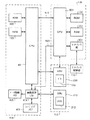
Next, a detailed hardware configuration of the display device with a
[0109]
The
[0110]
The
[0111]
The
[0112]
In the present embodiment, the
[0113]
When a plurality of optical units are independently driven, when a touch point is input to the coordinate
[0114]
As a result, all of the plurality of
[0115]
FIG. 16 shows the light emission and light reception timings of the
[0116]
The light emission timing of the
[0117]
Further, the
[0118]
The
[0119]
Light emitted from the
[0120]
The
[0121]
The
[0122]
Although a serial interface is used in the present embodiment, as another example, a dedicated interface may be used because communication is performed inside the apparatus.
[0123]
As described above, the present invention has been described using the embodiment. However, various changes or improvements can be added to the above embodiment.
[0124]
As a first modified example, in the present embodiment, the
[0125]
As described above, even when the
[0126]
As a second modification, the
[0127]
As described above, even when the
[0128]
As a third modification, the display device with a
[0129]
As a fourth modification, the
[0130]
【The invention's effect】
As described above, according to the first aspect of the present invention, even if the touch point coordinates cannot be accurately calculated based on the touch point direction detected by the direction detection means on one side, the other side Touch point coordinates can be calculated based on the touch point direction detected by the direction detecting means. Therefore, the coordinates of the touch point can be calculated more accurately. Further, the touch point coordinates can be accurately calculated based on both the touch point direction detected by the direction detection unit on one side and the touch point direction detected by the direction detection unit on the other side. To play.
[0131]
Further, since the direction detecting means can be arranged on both the first side and the second side, the degree of freedom of the arrangement position of each direction detecting means is increased, and each direction detecting means is arranged at a more appropriate position. It has the effect that it can be done.
[0132]
According to the second aspect of the present invention, even if the touch point coordinates cannot be accurately calculated based on the touch point direction detected by the direction detecting means on one side, the other direction detecting means detects the touch point coordinates. The touch point coordinates can be accurately calculated based on the touch point direction. Further, the touch point coordinates can be accurately calculated based on both the touch point direction detected by the direction detection unit on one side and the touch point direction detected by the direction detection unit on the other side. To play.
[0133]
According to the third aspect of the present invention, even if the touch point coordinates cannot be accurately calculated based on the touch point direction detected by the direction detecting means on one side, the other direction detecting means detects the coordinates. The touch point coordinates can be accurately calculated based on the touch point direction. Alternatively, the touch point coordinates can be accurately calculated based on both the touch point direction detected by the direction detection unit on one side and the touch point direction detected by the direction detection unit on the other side. To play.
[0134]
Further, according to the invention of claim 4, it is possible to prevent erroneous detection due to the direction detection of the other direction detecting means. Therefore, there is an effect that the touch point direction can be accurately detected.
[0135]
Further, according to the invention according to claim 5, it is possible to prevent each light receiving means from receiving the reflected light of the light emitted by the light emitting means arranged on different sides. Therefore, there is an effect that the touch point direction can be accurately detected.
[0136]
According to the invention according to claim 6, the light emitting means arranged on different sides emit light at different timings, that is, alternately, so that the light receiving means arranged on the same side in accordance with this timing. Receiving the reflected light of the emitted light, it is possible to prevent the light receiving means arranged on a side different from the light emitting means from receiving the reflected light of the light emitted by the light emitting means. . Therefore, there is an effect that the touch point direction can be accurately detected.
[0137]
Also, according to the invention according to
[0138]
Further, according to the invention according to claim 8, since the light receiving units arranged on the same side receive the reflected light at the same timing, the difference in the timing at which each light receiving unit detects the touch point direction is different. Accordingly, there is an effect that detection of a different touch point direction can be avoided.
[0139]
According to the ninth aspect of the present invention, all of the light emitting units arranged on the same side emit light at the same timing, so that different touch point directions are detected depending on the difference in light emission timing. This has the effect that it is possible to avoid doing so.
[0140]
According to the tenth aspect of the present invention, by arranging the optical unit in the gap between the coordinate input surface and the reflecting means, the optical unit is arranged on two sides without increasing the size of the entire coordinate input device. It has the effect that it can be done.
[0141]
According to the eleventh aspect of the present invention, since a gap corresponding to the passage area is provided between the reflecting means and the coordinate input surface, it is possible to prevent light from being blocked by the reflecting means. It works.
[0142]
According to the twelfth aspect of the present invention, since the reflecting means is provided with a width substantially equal to the width of the spread of the light, the light emitted from the optical unit on one side is converted into the optical unit on the other side. This has the effect that light reception can be avoided.
[0143]
According to the thirteenth aspect, since the touch point coordinates are calculated from each of two combinations of two different touch point directions, virtual touch point coordinates are calculated in addition to the true touch point coordinates. Even in this case, there is an effect that the true touch point coordinates can be accurately calculated from the above.
[0144]
According to the fourteenth aspect of the present invention, if the touch point coordinates of the simultaneously input touch points cannot be accurately calculated based on the touch point directions detected by the direction detecting means on one side, the other By calculating the touch point coordinates by further utilizing the touch point direction detected by the direction detecting means of the side, there is an effect that accurate touch point coordinates can be calculated.
[0145]
According to the invention according to claim 15, the calculation control means may further calculate the width of the touch point in the predetermined direction based on each of the angle ranges in the touch point direction based on the touch point direction. Therefore, the true touch point coordinates can be determined based on the value of the width. Therefore, there is an effect that accurate touch point coordinates can be calculated.
[0146]
According to the invention, when accurate touch point coordinates cannot be calculated based on the touch point direction detected by the direction detecting means, the touch is performed based on each of the angle ranges in the touch point direction. Since the width of the point can be calculated, there is an effect that the true touch point coordinates can be determined based on the width of the touch point.
[Brief description of the drawings]
FIG. 1 is a diagram showing a
FIG. 2 is a schematic diagram illustrating a positional relationship between an optical unit and a reflection unit.
FIG. 3 is a diagram illustrating an example of a relationship between a distance between an optical unit and a reflection unit;
FIG. 4 is a diagram for explaining the principle by which a
FIG. 5 is a flowchart showing processing of the display device with a touch panel when a coordinate input surface is touched.
FIG. 6 is a flowchart showing processing of the display device with a touch panel when a coordinate input surface is touched.
FIG. 7 is a diagram illustrating a process of calculating touch point coordinates from two combinations of optical units arranged on the lower side.
FIG. 8 is a diagram illustrating positions of two touch points A and B.
FIG. 9 is a diagram illustrating the positions of touch points N and M when the user touches the coordinate input surface with a touch pen with his / her hand.
FIG. 10 is a diagram showing points P and Q touched at the same time, and an optical unit detecting these as different touch point directions.
FIG. 11 is a diagram showing points P and Q touched at the same time, and an optical unit detecting these as different touch point directions.
FIG. 12 is a schematic diagram illustrating a relationship between touched points P and Q, and a touch point direction detected by a first optical unit and a second optical unit.
FIG. 13 is a diagram illustrating a detailed configuration of an optical unit.
FIG. 14 is a schematic diagram for explaining the principle of detecting the direction of a touch point by the
FIG. 15 is a diagram showing a detailed hardware configuration of a display device with a touch panel.
FIG. 16 is a diagram showing a light emission timing of a light emitting unit of each optical unit and a light receiving timing of a light receiving unit.
FIG. 17 is a diagram showing an arrangement of an optical unit according to a first modification.
FIG. 18 is a diagram showing an arrangement of an optical unit according to a second modification.
FIG. 19 is a diagram illustrating an example of a coordinate detection device according to the related art.
[Explanation of symbols]
100 Display device with touch panel
101 Coordinate input surface
102a-g Optical unit
103a-d reflector
104a-g Direction detector
105 Main control unit
106 Interface section
121 Light emitting unit
122 light source
123 lens
124 half mirror
125 light receiving section
126 Condenser lens
127 line sensor
200 light emitting unit
210 Light receiving unit
400 mirror
405 data storage memory
406 shading memory
504 Interface control unit
Claims (16)
前記座標入力面の第1の辺に近接して配置され、配置された位置を基準とする前記タッチ点の方向であるタッチ点方向を検知する少なくとも2つの第1の方向検知手段と、
前記座標入力面の第2の辺に近接して配置され、配置された位置を基準とする前記タッチ点の方向であるタッチ点方向を検知する少なくとも2つの第2の方向検知手段と、
前記第1の方向検知手段および前記第2の方向検知手段のうち少なくとも2つの方向検知手段が検知した前記タッチ点方向に基づいてタッチ点座標を算出する算出制御手段と
を備えたことを特徴とする座標検知装置。A coordinate detection device that detects the coordinates of a touch point input on a coordinate input surface,
At least two first direction detecting means arranged in proximity to a first side of the coordinate input surface and detecting a touch point direction that is a direction of the touch point with reference to the arranged position;
At least two second direction detecting means arranged near the second side of the coordinate input surface and detecting a touch point direction which is a direction of the touch point with reference to the arranged position;
Calculation control means for calculating touch point coordinates based on the touch point direction detected by at least two of the first direction detection means and the second direction detection means. Coordinate detection device.
前記座標入力面に平行な面に沿って扇状に広がる光を射出する発光手段と、
前記座標入力面を通過した光を反射する反射手段からの反射光を受光する受光手段と
を有し、
前記第1の辺に近接して配置された前記受光手段と、前記第2の辺に近接して配置された前記受光手段とは、それぞれ異なるタイミングで反射光を受光することを特徴とする請求項4に記載の座標検知装置。The direction detecting means,
A light emitting unit that emits light spreading in a fan shape along a plane parallel to the coordinate input surface,
Having light receiving means for receiving reflected light from reflecting means for reflecting light passing through the coordinate input surface,
The light receiving means arranged close to the first side and the light receiving means arranged close to the second side receive reflected light at different timings, respectively. Item 5. The coordinate detecting device according to item 4.
前記座標入力面に平行な面に沿って扇状に広がる光を射出する発光手段と、
前記座標入力面を通過した光を反射する反射手段からの反射光を受光する受光手段と
を有し、
前記第1の辺に近接して配置された前記発光手段と、前記第2の辺に近接して配置された前記発光手段とは、それぞれ異なるタイミングで光を射出することを特徴とする請求項4または5に記載の座標検知装置。The direction detecting means,
A light emitting unit that emits light spreading in a fan shape along a plane parallel to the coordinate input surface,
Having light receiving means for receiving reflected light from reflecting means for reflecting light passing through the coordinate input surface,
The light emitting means arranged close to the first side and the light emitting means arranged close to the second side respectively emit light at different timings. 6. The coordinate detecting device according to 4 or 5.
前記座標入力面に平行な面に沿って扇状に広がる光を射出する発光手段と、
前記座標入力面を通過した光を反射する反射手段からの反射光を受光する受光手段と
を有し、
前記座標入力面の同一の辺に近接して配置された複数の前記受光手段は、同一のタイミングで反射光を受光することを特徴とする請求項7に記載の座標検知装置。The direction detecting means,
A light emitting unit that emits light spreading in a fan shape along a plane parallel to the coordinate input surface,
Having light receiving means for receiving reflected light from reflecting means for reflecting light passing through the coordinate input surface,
8. The coordinate detecting device according to claim 7, wherein the plurality of light receiving units arranged close to the same side of the coordinate input surface receive the reflected light at the same timing.
前記座標入力面に平行な面に沿って扇状に広がる光を射出する発光手段と、
前記座標入力面を通過した光を反射する反射手段からの反射光を受光する受光手段と
を有し、
前記座標入力面の同一の辺に近接して配置された複数の前記発光手段は、同一のタイミングで光を射出することを特徴とする請求項7または8に記載の座標検知装置。The direction detecting means,
A light emitting unit that emits light spreading in a fan shape along a plane parallel to the coordinate input surface,
Having light receiving means for receiving reflected light from reflecting means for reflecting light passing through the coordinate input surface,
9. The coordinate detecting device according to claim 7, wherein the plurality of light emitting units arranged close to the same side of the coordinate input surface emit light at the same timing.
前記座標入力面に平行な面に沿って扇状に広がる光を射出する発光手段と、
前記座標入力面を通過した光を反射する反射手段からの反射光を受光する受光手段と
を有し、
前記座標入力面の前記第1の辺に近接し、かつ当該第1の辺側に配置された前記発光手段から射出された光が通過する通過領域に近接する位置に配置され、前記第2の辺側に配置された前記発光手段から射出された光を反射する反射手段をさらに備えたことを特徴とする請求項1から9のいずれか一項に記載の座標検知装置。The direction detecting means,
A light emitting unit that emits light spreading in a fan shape along a plane parallel to the coordinate input surface,
Having light receiving means for receiving reflected light from reflecting means for reflecting light passing through the coordinate input surface,
The second input side is located at a position close to the first side of the coordinate input surface and close to a passage area through which light emitted from the light emitting unit disposed on the first side passes. The coordinate detecting device according to claim 1, further comprising a reflection unit configured to reflect light emitted from the light emitting unit disposed on a side.
前記算出制御手段は、前記同一の辺側の前記方向検知手段のうち少なくとも3つの方向検知手段が2つの前記タッチ点方向を検知した場合に、2つのタッチ点方向の異なる2つの組み合わせそれぞれから、2つの前記タッチ点座標を算出し、いずれの組み合わせからも算出される2つの前記タッチ点座標を、真のタッチ点座標と決定することを特徴とする請求項1から12のいずれか一項に記載の座標検知装置。At least three different direction detecting means are provided at different positions on the first side,
The calculation control means, when at least three direction detection means among the direction detection means on the same side detect two touch point directions, respectively from two different combinations of two touch point directions, 13. The method according to claim 1, wherein two touch point coordinates are calculated, and two touch point coordinates calculated from any combination are determined as true touch point coordinates. The coordinate detecting device according to the above.
前記算出制御手段は、前記2つの方向検知手段が検知した2つの前記タッチ点方向の前記角度範囲のそれぞれに基づいて、前記タッチ点の所定の方向における幅をさらに算出し、互いに近似する幅に対応するタッチ点座標を、真の前記タッチ点座標として決定することを特徴とする請求項1から14のいずれか一項に記載の座標検知装置。The two direction detecting means arranged on the same side of the coordinate input surface respectively detect two touch point directions in an angle range with respect to the size of each of the two touch points,
The calculation control unit further calculates a width of the touch point in a predetermined direction based on each of the angle ranges of the two touch point directions detected by the two direction detection units, and sets the width to a width similar to each other. The coordinate detection device according to any one of claims 1 to 14, wherein a corresponding touch point coordinate is determined as the true touch point coordinate.
Priority Applications (1)
| Application Number | Priority Date | Filing Date | Title |
|---|---|---|---|
| JP2002355870A JP4118664B2 (en) | 2002-12-06 | 2002-12-06 | Coordinate detection device |
Applications Claiming Priority (1)
| Application Number | Priority Date | Filing Date | Title |
|---|---|---|---|
| JP2002355870A JP4118664B2 (en) | 2002-12-06 | 2002-12-06 | Coordinate detection device |
Publications (2)
| Publication Number | Publication Date |
|---|---|
| JP2004192065A true JP2004192065A (en) | 2004-07-08 |
| JP4118664B2 JP4118664B2 (en) | 2008-07-16 |
Family
ID=32756432
Family Applications (1)
| Application Number | Title | Priority Date | Filing Date |
|---|---|---|---|
| JP2002355870A Expired - Fee Related JP4118664B2 (en) | 2002-12-06 | 2002-12-06 | Coordinate detection device |
Country Status (1)
| Country | Link |
|---|---|
| JP (1) | JP4118664B2 (en) |
Cited By (7)
| Publication number | Priority date | Publication date | Assignee | Title |
|---|---|---|---|---|
| JP2005258810A (en) * | 2004-03-11 | 2005-09-22 | Canon Inc | Coordinate input device, control method therefor, and program |
| JP2011070625A (en) * | 2009-09-24 | 2011-04-07 | Acer Inc | Optical touch control system and method thereof |
| US20110304535A1 (en) * | 2010-06-15 | 2011-12-15 | Canon Kabushiki Kaisha | Coordinate input apparatus |
| CN102043543B (en) * | 2009-10-09 | 2013-11-20 | 宏碁股份有限公司 | Optical touch system and method thereof |
| JP2014510341A (en) * | 2011-02-28 | 2014-04-24 | バーント インターナショナル リミテッド | System and method for detecting and tracking radiation shielding on a surface |
| US8791925B2 (en) | 2010-11-04 | 2014-07-29 | Canon Kabushiki Kaisha | Coordinate input apparatus, control method therefor and program |
| JP2016186673A (en) * | 2015-03-27 | 2016-10-27 | 株式会社Nttドコモ | Position detection device and position detection method |
Families Citing this family (3)
| Publication number | Priority date | Publication date | Assignee | Title |
|---|---|---|---|---|
| JP5973849B2 (en) | 2012-03-08 | 2016-08-23 | キヤノン株式会社 | Coordinate input device and sensor bar used for coordinate input device |
| JP6031293B2 (en) | 2012-08-03 | 2016-11-24 | キヤノン株式会社 | Coordinate input device, control method therefor, and program |
| JP6021531B2 (en) | 2012-08-31 | 2016-11-09 | キヤノン株式会社 | Coordinate input device, control method therefor, and program |
-
2002
- 2002-12-06 JP JP2002355870A patent/JP4118664B2/en not_active Expired - Fee Related
Cited By (9)
| Publication number | Priority date | Publication date | Assignee | Title |
|---|---|---|---|---|
| JP2005258810A (en) * | 2004-03-11 | 2005-09-22 | Canon Inc | Coordinate input device, control method therefor, and program |
| JP2011070625A (en) * | 2009-09-24 | 2011-04-07 | Acer Inc | Optical touch control system and method thereof |
| EP2302491A3 (en) * | 2009-09-24 | 2014-07-02 | Acer Incorporated | Optical touch system and method |
| CN102043543B (en) * | 2009-10-09 | 2013-11-20 | 宏碁股份有限公司 | Optical touch system and method thereof |
| US20110304535A1 (en) * | 2010-06-15 | 2011-12-15 | Canon Kabushiki Kaisha | Coordinate input apparatus |
| US9063618B2 (en) * | 2010-06-15 | 2015-06-23 | Canon Kabushiki Kaisha | Coordinate input apparatus |
| US8791925B2 (en) | 2010-11-04 | 2014-07-29 | Canon Kabushiki Kaisha | Coordinate input apparatus, control method therefor and program |
| JP2014510341A (en) * | 2011-02-28 | 2014-04-24 | バーント インターナショナル リミテッド | System and method for detecting and tracking radiation shielding on a surface |
| JP2016186673A (en) * | 2015-03-27 | 2016-10-27 | 株式会社Nttドコモ | Position detection device and position detection method |
Also Published As
| Publication number | Publication date |
|---|---|
| JP4118664B2 (en) | 2008-07-16 |
Similar Documents
| Publication | Publication Date | Title |
|---|---|---|
| JP4208394B2 (en) | Coordinate input device | |
| US7589715B2 (en) | Coordinate input apparatus, control method thereof, and program | |
| KR100707847B1 (en) | Coordinate input apparatus and its control method | |
| US7522156B2 (en) | Optical scanning-type touch panel | |
| KR20060043856A (en) | Coordinate input device and control method | |
| US20040218479A1 (en) | Optical position detecting device and recording medium | |
| JP2001265516A (en) | Coordinate input device | |
| US20080291164A1 (en) | Coordinate input apparatus, control method thereof, and program | |
| EP2250546A2 (en) | Systems and methods for resolving multitouch scenarios for optical touchscreens | |
| JP4118664B2 (en) | Coordinate detection device | |
| KR101789906B1 (en) | Optical touch screens | |
| JP2003303046A (en) | Optical coordinate detection device | |
| US20100073289A1 (en) | 3d control of data processing through handheld pointing device | |
| JP4160810B2 (en) | Coordinate detection device | |
| JP2013210956A (en) | Display device | |
| JP2003241872A (en) | Drawing processing method, program according to the method, and storage medium storing the program | |
| JPH1185376A (en) | Information display device with optical position detector | |
| JP2007206935A (en) | Coordinate detection system, coordinate detection device, coordinate detection method and touch pen | |
| JP4052908B2 (en) | Optical coordinate input system | |
| JP2000089903A (en) | Optical scanning touch panel | |
| JP3847005B2 (en) | Optical scanning touch panel | |
| JP2003202957A (en) | Coordinate detection method, program according to the method, and storage medium storing the program | |
| JP4118665B2 (en) | Coordinate detection device | |
| JP4175715B2 (en) | Optical scanning touch panel | |
| JP2003122494A (en) | Coordinate input / detection device and coordinate input / detection method |
Legal Events
| Date | Code | Title | Description |
|---|---|---|---|
| A621 | Written request for application examination |
Free format text: JAPANESE INTERMEDIATE CODE: A621 Effective date: 20051125 |
|
| A131 | Notification of reasons for refusal |
Free format text: JAPANESE INTERMEDIATE CODE: A131 Effective date: 20080108 |
|
| A521 | Written amendment |
Free format text: JAPANESE INTERMEDIATE CODE: A523 Effective date: 20080306 |
|
| TRDD | Decision of grant or rejection written | ||
| A01 | Written decision to grant a patent or to grant a registration (utility model) |
Free format text: JAPANESE INTERMEDIATE CODE: A01 Effective date: 20080422 |
|
| A61 | First payment of annual fees (during grant procedure) |
Free format text: JAPANESE INTERMEDIATE CODE: A61 Effective date: 20080423 |
|
| R150 | Certificate of patent or registration of utility model |
Free format text: JAPANESE INTERMEDIATE CODE: R150 |
|
| FPAY | Renewal fee payment (event date is renewal date of database) |
Free format text: PAYMENT UNTIL: 20110502 Year of fee payment: 3 |
|
| FPAY | Renewal fee payment (event date is renewal date of database) |
Free format text: PAYMENT UNTIL: 20120502 Year of fee payment: 4 |
|
| FPAY | Renewal fee payment (event date is renewal date of database) |
Free format text: PAYMENT UNTIL: 20130502 Year of fee payment: 5 |
|
| FPAY | Renewal fee payment (event date is renewal date of database) |
Free format text: PAYMENT UNTIL: 20140502 Year of fee payment: 6 |
|
| S111 | Request for change of ownership or part of ownership |
Free format text: JAPANESE INTERMEDIATE CODE: R313113 |
|
| FPAY | Renewal fee payment (event date is renewal date of database) |
Free format text: PAYMENT UNTIL: 20140502 Year of fee payment: 6 |
|
| R350 | Written notification of registration of transfer |
Free format text: JAPANESE INTERMEDIATE CODE: R350 |
|
| LAPS | Cancellation because of no payment of annual fees |