JP2004192995A - Fuel cell device - Google Patents
Fuel cell device Download PDFInfo
- Publication number
- JP2004192995A JP2004192995A JP2002360700A JP2002360700A JP2004192995A JP 2004192995 A JP2004192995 A JP 2004192995A JP 2002360700 A JP2002360700 A JP 2002360700A JP 2002360700 A JP2002360700 A JP 2002360700A JP 2004192995 A JP2004192995 A JP 2004192995A
- Authority
- JP
- Japan
- Prior art keywords
- flow path
- air
- water
- fuel cell
- gas flow
- Prior art date
- Legal status (The legal status is an assumption and is not a legal conclusion. Google has not performed a legal analysis and makes no representation as to the accuracy of the status listed.)
- Pending
Links
Images








Classifications
-
- Y—GENERAL TAGGING OF NEW TECHNOLOGICAL DEVELOPMENTS; GENERAL TAGGING OF CROSS-SECTIONAL TECHNOLOGIES SPANNING OVER SEVERAL SECTIONS OF THE IPC; TECHNICAL SUBJECTS COVERED BY FORMER USPC CROSS-REFERENCE ART COLLECTIONS [XRACs] AND DIGESTS
- Y02—TECHNOLOGIES OR APPLICATIONS FOR MITIGATION OR ADAPTATION AGAINST CLIMATE CHANGE
- Y02E—REDUCTION OF GREENHOUSE GAS [GHG] EMISSIONS, RELATED TO ENERGY GENERATION, TRANSMISSION OR DISTRIBUTION
- Y02E60/00—Enabling technologies; Technologies with a potential or indirect contribution to GHG emissions mitigation
- Y02E60/30—Hydrogen technology
- Y02E60/50—Fuel cells
Landscapes
- Fuel Cell (AREA)
Abstract
【目的】燃料電池単位セルのスタックに組み込まれる冷却ガス流路へ空気及び水を供給してこれを冷却する新規構成のセパレータを備えた燃料電池装置について、その好適な運転機能を提供する。
【構成】この発明の新規構成のセパレータは冷却ガス流路及び該冷却ガス流路と空気流路とで共有される第1の壁部を備え、該第1の壁部には冷却ガス流路の空気及び水蒸気をを前記空気流路へ移送する連通孔が形成されている。そして、かかる新規構成のセパレータを備える燃料電池装置において、単位セルの運転状況に応じて水の供給をオンオフで行うとともに、空気は常に供給しつつその増減を行う。
【選択図】 図2A fuel cell device provided with a separator having a novel configuration for supplying air and water to a cooling gas flow channel incorporated in a stack of fuel cell unit cells and cooling the same is provided with a preferable operation function thereof.
The separator of the present invention has a cooling gas flow path and a first wall shared by the cooling gas flow path and the air flow path, and the first wall has a cooling gas flow path. A communication hole for transferring the air and water vapor to the air flow path is formed. In the fuel cell device including the separator having such a novel configuration, the supply of water is turned on and off in accordance with the operation state of the unit cell, and the amount of air is constantly increased and decreased.
[Selection] Fig. 2
Description
【0001】
【発明の属する技術分野】
この発明は燃料電池装置に関する、特に高分子固体電解質膜を有するいわゆるPEM型の燃料電池装置の改良に関する。
【0002】
【従来技術】
PEM型の燃料電池装置の電池単位セルは、燃料極(水素を燃料極とする場合は水素極ともいう)と空気極(酸素が反応ガスであるので酸素極ともいう。また酸化極ともいう)との間に高分子固体電解質膜が狭持された構成である。空気極と電解質膜との間には触媒を含む反応層が介在されている。
【0003】
このような構成の燃料電池の起電力は、燃料極側(アノード)に燃料ガスが供給され、空気極側に酸化ガスが供給された結果、電気化学反応の進行に伴い電子が発生し、この電子を外部回路に取り出すことにより、発生される。即ち、燃料極(アノード)にて得られる水素イオンがプロトン(H30+)の形態で、水分を含んだ電解質膜中を空気極(カソード)側に移動し、また燃料極(アノード)にて得られた電子が外部負荷を通って空気極(カソード)側に移動して酸化ガス(空気を含む)中の酸素と反応して水を精製する、一連の電気化学反応による電気エネルギーを取り出すことができる(例えば、特許文献1参照。)。
【0004】
このような燃料電池の単位セル単独では充分なパワーが得られないので、多数の単位セルを直列に重ね合わせたいわゆるスタックが用いられる。このスタックにおいては単位セルが密に重ね合わされるので、その過熱を防止する必要がある。そのため従来では、スタック中に冷却盤を組み込み、水冷若しくは空冷方式でその冷却を行っていた。
特許文献2においては当該冷却手段として、スタックの内部に冷却ガス流路を設け、この冷却ガス流路へ水を添加した空気を送り、その空気が冷却ガス流路を通過させた後にこれを空気極側の空気流路へ送っている。空気に添加された水は冷却ガス流路においてスタックと熱交換して蒸発する。そして当該蒸気を含んだ空気が空気流路へ送られることにより空気極の加湿効果が奏される。なお、メインテナンスフリーの見地から水を再利用するため、冷却ガス流路と空気流路との間に凝縮器が配設される。
かかる燃料電池装置によれば、簡単な構成でスタックが効率的に冷却され、高出力密度への対応が可能で、かつ軽量で低コストの冷却手段が提供されることとなる。
本発明に関連する発明として、特許文献3も参照されたい。
【0005】
【特許文献1】
特開2002−15760号公報
【特許文献2】
特開平10−247505号公報
【特許文献3】
特開2001−332278号公報
【0006】
【発明が解決しようとする課題】
特許文献2に記載の燃料電池装置によれば、水の添加された空気はスタック内の冷却ガス流路を通過した後、再びスタック内の空気流路へ戻される。冷却ガス流路での熱交換により昇温された空気がスタック外に出てそこで冷却されると、飽和水蒸気量が小さくなるので空気中から水分が露結等により除去される。その後スタック内の空気流路へ戻され再び昇温された空気は水蒸気で飽和した状態とならず、空気極を乾燥させるおそれがある。特に、冷却ガス流と空気流路との間に凝縮器が介在された場合には、空気中から水分が強制的に凝縮除去されるので、空気極の乾燥の問題が生じやすい。
そこでこの発明は、新規な構成のセパレータを備えた燃料電池装置と当該燃料電池装置の適切な運転方法を提供することを目的とする。
【0007】
【課題を解決するための手段】
この発明は上記課題を解決するためになされたものである。即ち、
一対の燃料電池の単位セルと、
該単位セル間に配置されて前記一方の単位セルとの間に空気流路を形成し、前記他方の単位セルとの間に燃料ガス流路を形成するセパレータであって、冷却ガス流路を備え、該冷却ガス流路の周壁が前記単位セルと熱的に連結されているセパレータと、
前記セパレータの冷却ガス流路へ水を液体の状態で供給する水供給装置と、
前記冷却ガス流路へ空気を供給する空気供給装置と、
を備える燃料電池装置において、
前記セパレータには前記冷却ガス流路と前記空気流路とを連通する連通路が形成され、
前記単位セルの運転状況を検出する運転状況検出装置が備えられ、
検出された運転状況に応じて、前記水供給手段による水を供給をオンオフ制御で行うとともに、前記空気供給装置による空気供給量の調整は空気流通量の増減で行う、ことを特徴とする燃料電池装置。
【0008】
このように構成された燃料電池装置によれば、セパレータ内に連通路が形成され、冷却ガス流路と空気流路が連通されているので、冷却ガス流路の空気がそのままの状態で、即ち温度及び蒸気量を維持した状態で、空気流路へ導入されることとなる。従って、燃料電池単位セルの空気極が乾燥することを確実に防止できる。このような冷却・加湿方式において、検出された運転状況に応じて、前記水供給装置による水の供給をオンオフ制御で行うとともに、前記空気供給手段による空気供給量の調整は空気流通量の増減で行うことにより、可及的に少量のエネルギーで水供給装置及び空気供給装置を駆動させ、効率よくスタックの温度調整及び空気流路へ必要な水分の供給をすることができる。
【0009】
上記において、単位セルは汎用的なものを用いることができる。スタック中において全ての単位セル間に上記規定のセパレータを配設する必要はない。
単位セルの熱と冷却ガスである水の添加された空気は冷却ガス流路の周壁において熱交換される。従って、冷却ガス流路の周壁は一対の単位セルそれぞれと接触しかつ熱伝導率の高い材料で形成されることが好ましい。勿論、単位セルの熱を他の部材により冷却ガス流路の周壁まで伝導させてもよい。
連通路は、セル内にあり冷却ガス流路内の気体成分(空気及び水蒸気)の温度や湿度を維持したままこれを空気流路へ送り込めるものであれば特に限定されないが、冷却ガス流路と空気流路とを隔てる壁部を貫通する貫通孔とすることが好ましい。これにより、連通路の構成、ひいてはセパレータの構成が簡素化されて安価な燃料電池装置の提供が可能になる。
空気供給装置として例えばファンを用いることができる。この発明では、空気の供給は常にオンにしておいてその供給量を増減制御しようとするものである。ここに、ラム風その他の風の影響により実質的に冷却ガス流路に空気が供給され、それが連通路を介して空気流路まで供給されるものであれば、空気供給装置としてのファンを止めることができる。
ファンはその風量、即ち空気供給量をリニアに変更させられるものであることが好ましい。これにより、スタックの温度調整をより精密に行うことができる。
【0010】
このように構成された燃料電池装置のよれば、第1に、空気マニホールド内で水を噴射混入させた空気を、セパレータに形成した冷却ガス流路から連通路を経て空気流路に供給する方式のものを提案している。この方式では、冷却ガス流路の周壁に伝わる単位セルの熱により蒸発する水の潜熱により単位セルが冷却され、蒸気化した水が空気と共に空気流路に供給されることとなる。これによりセパレータを介して単位セルを冷却しながら、空気流路への液体水又は霧状の水の侵入による流路の閉塞が防止される。即ち、上記のような仕組みの燃料電池装置の場合、冷却ガス流路に供給された空気と水は、燃料電池の発電時に発生する発熱を潜熱冷却するのに使われる。そして、液体の状態で供給された水の一部は冷却ガス流路内で蒸発し、空気とともに水蒸気として連通路から空気流路へ供給され、空気は燃料電池の反応に使われ、水蒸気は加湿に使われる。
【0011】
また第2に、空気の供給量が可変となるので、空気の供給量を変化させてこれを最適量とすることにより、冷却流路に供給された水の潜熱を利用する冷却が十分かつ効率良く行われる。これにより、セパレータひいては燃料電池単位セルが効率よく冷却されることとなる。なお、水の潜熱を効率良く利用する手段として、水の粒径は50μm〜500μmとすることが好ましい。燃料電池単位セルの電解質膜の厚さは200μm以下であることが望ましい。即ち、燃料電池の温度が高温で運転されてこれの温度を下げたいときには、充分量の水が供給されている下で空気の供給量(送風量、単位時間当たりの供給される空気量、単位時間当たりに冷却ガス流路S2、空気流路S1(図7参照)を通過する空気量)を大きくする。空気供給量が固定のタイプでは、水の顕熱を利用するため多量の水を供給する必要上種々の不具合があったが、空気供給量を多くしても不具合はほとんど生じない。空気供給量を多くしたとしても空気供給装置(ファンなど)にかかる負荷は水量増大の場合にかかる負荷に比べて無視できるほど小さいからである。燃料電池が低温で運転されてこれの温度を上げたいときには、空気供給量が過剰とならないように風量を落とす。これにより、燃料電池の温度を確実に上げることができると共に、空気供給装置で消費される電力を可及的に小さくし、もって動力損の低減を図る。また、水リサイクル用の凝縮器についても、内部温度が上がり外気との温度差が大きくなるので、その容量を小さくできる。
【0012】
さらにこの発明によれば、液体である水の供給が燃料電池セルの運転温度などの運転状況に応じてオンオフ制御される。水の供給にオフの時間を設けることにより、水の過剰供給を防止できるとともに液体供給装置の消費電力を可及的に低減できる。オン・オフで制御されるため、オン時に多量の水を噴射してもオフの時間を調整することで単位時間当たりの平均吸水量を一定に制御できる。オン時に多量の水を噴射させることにより冷却空間に対して水を均一にかつ確実に供給できることとなる。このように、空気の送風量及び/又は液体の供給量を制御することにより燃料電池単位セルの運転状況(運転温度)を所定の範囲内に収めることが可能となる。
水の代わりに又は水と併用してアルコールなどの液体を用いることができる。
【0013】
この発明によれば、空気の供給量と水の供給量とが独立しているので、それらが独立していない供給系に比べて、空気と水のそれぞれを必要なタイミングで必要な供給量を独立して制御することができる。そのことによって、無駄がなく効率的に高い燃料電池の出力が得られる。また、回収する空気、水の量も最小限にすることができるので、凝縮器も小さくすることができ、補機による消費電力の節約にもなる。また、起動にかかる時間も短縮できる。
【0014】
図1は各ストイキ比における燃料電池の負荷(電流密度)と温度(空気排気温度)との理論上の関係を示す。ここに、ストイキ比とは、燃料電池反応で消費される理論上の酸素量を含む空気量を基準として空気極に供給される空気量を規定したものである。従って、ストイキ比が1の場合は、理論上必要な最小限の空気量が送られる場合であり、ストイキ比が2になると空気供給量はストイキ比1の時の2倍となる。図1より、ストイキ比が小さいほど、即ち空気供給量が少ないほど同じ負荷を得るのに高い温度で燃料電池を運転できることがわかる。燃料電池の運転温度はこれが高ければ高いほど効率が高くなる。またその高温運転により排出空気の温度も上がるので凝縮器の容量を小さくすることもできる。従って、要求される負荷を賄える最も高い温度で燃料電池単位セルを運転することが好ましい。負荷と燃料電池の温度とはストイキ比により一義的に決められるので、負荷と温度の一方を検出してストイキ比、即ち空気供給量(厳密には空気流路入口での供給量)を決めればよいことになる。
【0015】
しかしながら現状の燃料電池では運転温度とストイキ比(空気供給量)とに各種の制限がある。例えば、燃料電池単位セルの焼きつきを確実に防止するため、その運転温度は、例えば100〜80℃以下とする必要がある。また、本発明者らの検討によれば、図1に示す破線Lより上側の条件での運転は不可能であった。これは、空気供給量が少ないときには(風量が小さい時には)、空気供給路やガス拡散層の抵抗、触媒の能力等のため空気が空気極に充分届かないなどの理由によるものと推定される。従って、図1において、例えば80℃以下でかつ破線Lより下側の領域で燃料電池は運転可能である。そして、その効率を考慮すれば、当該運転可能領域の最高温度側でこれを運転することが好ましい。
【0016】
負荷変動の激しい車両用の燃料電池装置では、要求される負荷に応じて空気供給量を変化させる。そのとき同時に燃料電池の温度を検出して、要求された負荷を実現できる最高温度、即ち最小のストイキ比(空気供給量)となるように空気供給量を調整することが好ましい。一方、ほとんど負荷が変動しない環境で使用される燃料電池装置においては、実質的に燃料電池の温度のみを監視して、その温度が変動したときのみこれが所望の温度となるように空気供給量を調節すればよい。即ち、燃料電池の温度が所望の温度範囲より低くなった場合には空気供給量を低減させて水の潜熱を利用した冷却効果を下げ、他方燃料電池の温度が所望の温度範囲より高くなった場合には空気供給量を増大して水の潜熱を利用した冷却効果を上げる。外部の環境や補機の性能により燃料電池装置の運転条件には様々な制限が課せられる。場合によっては、燃料電池の運転条件が図1における運転可能条件領域において四角で示した領域に限られることがある。この領域では、燃料電池の運転温度はストイキ比1のラインを超えることはない(燃料電池を常に稼動させておくため常に少なくともストイキ比1に対応した空気量が供給されているものとする。)。従って、燃料電池の温度を監視する必要はない。よって、負荷のみを監視して当該負荷を出力可能な最低量の空気が供給されるようにする。
【0017】
上記いずれの場合においても、冷却流路には常に充分な量の水が供給されているものとする。即ち、燃料電池の熱により蒸発するものがあっても、空気極及びその周囲(即ち空気流路内)には、燃料電池装置の運転中は常に液体状の水が存在しているものとする。このように冷却ガス流路並びに空気流路内に水が常に存在しているものとする。このように空気極に水が常に存在するので水の潜熱を効率良く利用できることとなる結果、燃料電池のスタックから冷却板を間引いたりこれを省略することができる。充分な量の水の蒸発が確保できないおそれのある場合を考慮して、冷却板若しくは冷却パイプその他の冷却装置を燃料電池のスタックに備えておくことが好ましい。かかる冷却装置へ流通する熱媒体(通常は水)によりスタックの熱を外部に取り出し、車内の暖房などに利用することができる。(いわゆるコジェネとして利用)。
【0018】
上記において、空気は実質的に圧縮されずに供給されるものである。なお、この発明は加圧された酸化ガス供給系を備えるタイプの燃料電池装置に適用することもできる。酸化ガス供給系に酸化ガスの圧縮機が備えられる場合はもとより、ガス配管の管路抵抗によって系内が大気圧より高い圧力となる場合も当該加圧された酸化ガス供給系に含まれる。燃料電池の温度は当該燃料電池単位セルに温度計を付設してこれを測定できることは勿論であるが、図1に示すように、排気空気の温度を測定することによりその温度を間接的に測定することも可能である。この場合、燃料電池から排出された直後の空気の温度を測定することが好ましい。燃料電池の負荷は、燃料電池単位セルの両極間の電流と電圧の積である。空気の供給量を制御するときに参考とするパラメータとしては、燃料電池単位セルが確実に出力している現在の負荷を検出し、これを用いることができる。その他、燃料電池に次に要求される負荷、例えば速度、トルク若しくはアクセルの開度を検出し、これを当該パラメータとして用いることもできる。
【0019】
【実施例】
次に、この発明の実施例について説明をする。図2は実施例の燃料電池装置1の概略構成を示す。図2に示すように、この装置1は燃料電池スタック、燃料ガスとしての水素ガス供給系20、空気供給系30、水供給系40から概略構成される。
【0020】
まず、燃料電池スタックについて説明する。燃料電池単位セル10Aの単位ユニットは空気極11と燃料極13とで固体高分子電解質膜12を狭持した構成である。実際の装置ではこの単位ユニットとセパレータ10Bが交互に複数枚積層して燃料電池スタックを構成している。空気流路S1、冷却ガス流路S2の上方及び下方にはそれぞれ空気を吸入、排気するための空気マニホールド14、15が形成されている。空気流路S1の上端には蓋18が被せられてここから空気及び水が直接空気流路S1内へ導入されることを禁止している。上方のマニホールド14にはノズル41を取付けるための取付孔が形成されている。ノズル41から噴出される水の噴出角度には制限があり、かつ水を霧状にしてこれを燃料電池スタックの全てのセパレータの冷却ガス流路に行き渡らせるには、ノズルと燃料電池スタックとの間に所定の間隔が必要になる。従って、このマニホールド14は比較的背の高いものとなる。一方、下側の空気マニホールド15は滴下した水を効率よく排出できるものとする。なお、ノズルはマニホールド14の側面に設けることもできる。かかるノズルより噴出される水はマニホールド14内の全域に行き渡り、よって冷却ガス流路全体の全面に行き渡ることとなる。ノズルをマニホールド14の側面に設けることにより、低いマニホールドが採用できる。よって燃料電池の小型化を図ることができる。
【0021】
ノズルは冷却ガス流路入口へ向けて直接水を噴射することが好ましい。これにより空気供給量の如何に拘わらず、所望の量の水を冷却ガス流路に供給することができる。即ち、空気の供給量と水の供給量とを独立して制御可能となる。また、起動時など大きな空気供給量(風量)の状態においても所望量の水を確実に冷却ガス流路内に供給できる。よって、起動時間の短縮が図れる。空気供給量の変更と水供給量の変更とは常に同時に要求されるわけではなく、独立してそれらの変更が必要となる場合がある。例えば、空気の供給量のみの変更が必要な場合に水の供給量までもが変更されてしまうと、燃料電池単位セルの制御のレスポンスが遅くなり、ひいては燃料電池装置の出力低下を招く恐れがある。これに対し、本発明では、必要なタイミングで必要な量の水及び/又は空気を供給できるので、燃料電池を効率良く制御できる。また、水と空気の供給を独立して制御することにより、無駄な空気及び無駄な水の供給を避けられる。この点においても、燃料電池の稼動が効率的になる。更には、無駄な水や無駄な空気の供給を避けることにより、凝縮器の容量も小さくすることができる。
【0022】
次に水素ガス供給系について説明する。水素ガス供給系20の水素供給装置21として、この実施例では高圧タンクからなる水素ボンベを利用した。その他、液体水素の水素ボンベ、水/メタノール混合液等の改質材料を改質器にて改質反応させて水素リッチな改質ガスを生成させ、この改質ガスをタンクに貯留しておいてこれを水素源とすることもできる。勿論、燃料電池装置1を室内で固定して使用する場合には、水素配管を水素源とすることができる。水素供給装置21と燃料ガス流路S3とは水素供給調圧弁23を介して水素ガス供給路22により接続されている。調圧弁23は燃料極13に供給する水素ガスの圧力を調整するものであり、汎用的な構成のものを利用できる。
【0023】
燃料ガス流路S3からの排気ガスは外気へ排出される。なお、この排気ガスを空気マニホールドへ供給し、ここで空気と混合することもできる。
【0024】
次に空気供給系について説明する。空気流路S1には冷却ガス流路S2から連通行143を介して空気が供給される。図の符号31は空気の供給路であり空気マニホールド14に連結されている。下側のマニホールド15には空気流路S1を通過した空気を循環若しくは排気するための空気路32が連結され、水を分離する凝縮器33を介して排気ガスは排気路36へ送られる。空気排気調圧弁34の開度により排気路36から排気される量が調節される。また、排気調圧弁34を省略し、排気ガスをそのまま大気へ排出する構成とすることもできる。かかる空気供給系30においては、空気圧縮機は特に備えられておらず、系全体に渡って実質的に大気圧が維持される。符号39は排出された空気の温度を検出するための温度計である。
【0025】
凝縮器33で分離された水はタンク42へ送られる。タンク42には水位センサ43が付設される。この水位センサ43により、タンク42の水位が所定の値以下となると、アラーム44が点滅してオペレータに水不足を知らせる。それとともに、凝縮器33の能力を変化させて水の回収量を調整することが好ましい。即ち、水が不足しているときは凝縮器33のファンの回転数を高めて水をより多く回収し、他方水が過剰になると凝縮器33のファンの回転数を低下若しくは停止して水の回収量を少なくする。
【0026】
次に水供給系について説明する。実施例の水供給系40では、タンク42から水供給路45がポンプ46、水圧センサ47及び調圧弁48を介して、ノズル41まで連結されている。調圧弁48により所望の水圧に調節された水はノズル41から吹き出して空気マニホールド14内では霧状になる。そして吹き出し時の運動量(初速)、霧の自重および空気流等によって燃料電池スタックの各セパレータ10Bの冷却ガス流路S2の上部開口から冷却ガス流路S2に入り、蒸気化されて空気流路S1を経て各単電池の空気極11側に供給されるものを除き冷却ガス流路S2の排出部を構成する下部開口から筐体下部に排出され、水タンク42に回収される。水量及び水の供給は、調圧弁とノズルとの組み合わせに限定されるものではない。
【0027】
さらに燃料電池装置に配置される計測器について説明する。図中の符号50は電流計であり、空気極11と燃料極13との間の電流を計測する。電流計50により計測された電流より図1の電流密度が求められる。この実施例では抵抗51が一定のため、両極11、13間の電流を測定することにより燃料電池単位セル10Aに掛かっている負荷(=仕事)が求められる。燃料電池装置を車両用に使用するときには両極間の電流と電圧を共に測定し、もって燃料電池単位セルに掛かっている負荷(燃料電池単位セルが現在出力しているパワー)を得ることが好ましい。車両用の場合には、速度、トルク若しくはアクセルの開度から燃料電池単位セルに要求されるパワーを予測してその値を用いることもできる。
【0028】
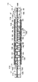
前述の燃料電池スタックは、板状の単電池10を板厚方向に多数積層集合させて構成されている。単電池は、図3の横断面、図4の縦断面で示すように単位セル10Aとセパレータ10Bとで構成されている。なお、説明の都合上、図3には隣接する単位セルも併せて示し、図4では単位セルの図示は省略されている。単位セル10Aは、固体高分子電解質膜12を空気極11と燃料極13とで狭持したものとされており、セパレータ10Bは、その詳細な構造については後に詳記するが、2枚合わせの薄板金属板140、150の四囲を絶縁体枠160、170で囲った構造とされている。セパレータ10Bには、燃料供給系20の水素供給路22に連通する水素流路L1、L2と、空気供給系30の空気マニホールド14に冷却ガス流路S2を介して連通する空気流路S1が形成されており、燃料電池スタックは、水素流路L1、L2を水平方向、空気流路S1を垂直方向に向けた姿勢で、空気マニホールド14に接続された収容筐体内に配置されている。
【0029】
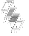
次に各単電池10の単位セル10A間に介挿されるセパレータ10Bの詳細な構成を説明する。図5に構成部材を分解して示すように、セパレータ10Bは、単位セル10Aの空気極11と燃料極13(図3参照)に接触して電流を外部に取り出すための対を成す枠体160、170とを備えている。集電部材140、150は、この形態では、薄板金属板、例えば板厚が0.1mm程度のもので構成されている。この構成金属は、導電性と耐食性を備えた金属で、例えば、ステンレス、ニッケル合金、チタン合金等に耐蝕導電処理を施したもの等が挙げられる。
【0030】
一方の集電部材140は、横長の矩形の板材からなり、プレス加工によって、複数の凸部141が押出し成形されている。これら凸部141は、連続する直線状で、板材の縦辺(図示の形態における短辺)に平行に等間隔で、板面を完全に縦断する配置とされ、下部が板厚方向に押し潰されて偏平化されている。これら凸部141の偏平化部分141´を除く部分の断面形状は、図3では、便宜上大まかに矩形波状断面で示されているが、プレス加工の型抜きの関係から、根元側が若干裾広がりの形状とするのがより実際的である。これら凸部141の間に画定され、単位セル10Aの空気極11に面する側が開いた溝状の空間S1は、後に詳記するように、空気極11側に空気を流通させる空気流路として使用される。各凸部141の頂部142の平面は、空気極11が接触する当接部となっている。また、凸部141の裏側に画定される溝状の空間S2は、同じく後に詳記する冷却ガス流路(本実施例では流路)として使用される。そして、これら空気流路S1と冷却ガス流路S2を部分的に連通させるべく、集電部材14を貫通する多数の通孔143が形成されている。これら通孔143の開設位置は任意であるが、凸部141の両側面が常識的である。さらに、集電部材140の横辺(図示の形態における長辺)方向の両端部近傍には、縦方向に長い長円孔144が形成されている。この長円孔144は、集電部材140を集電部材150と枠体160、170とに重ねてセパレータ10Bを積層した場合に、これら各部材を整合して貫通する水素流路L1、L2を構成する。
【0031】
他方の集電部材150は、集電部材140と合致する矩形の板材からなり、プレス加工によって、複数の凸部151が押出し成形されている。凸部151は、頂部152が平坦で、断面形状も、先の凸部141の場合と同様に実質上矩形波状とされているが、この形態の場合の凸部151は、縦方向に間欠的に設けられている。すなわち、凸部151は、横方向(長辺方向)の配設ピッチを集電部材140の凸部141の配設ピッチに合わせ、縦方向(短辺方向)の配設ピッチを適宜の間隔とした円形又は矩形の突起とされている。図3における左半分の断面は、これら凸部151の配列部分での裁断面を表し、右半分の断面は、配列部分間での裁断面を表す。これら凸部151の間に形成される縦横の空間S3は、単位セル10Aの燃料極13に面する側が開いた面状の空間を構成し、燃料である水素が流通する水素流路とされる。これら凸部151の頂部152の平面は、燃料極13が接触する当接部となっている。また、凸部151の裏側は、集電部材140に面する側が開いた短筒状の空間S4となっていて、集電部材140の空間S2に合わさっており、結果的に冷却ガス流路S2を介して、両端が板材の長辺部に開口する開口部を備える構成となる。この集電部材150にも、集電部材140と同様に長辺方向の両端部近傍に、短辺方向に長い長円孔153が形成され、集電部材140と枠体150、160とに重ねてセパレータ10Bを積層した場合に、これら各部材を整合して貫通する水素流路L1、L2を構成する。この形態において、凸部151を燃料極13に対して小面積で間欠的に当接する短柱状としているのは、これにより柱状の凸部151の間をぬう水素流路S3が縦横に形成され、水素ガスの流れの滞留やよどみを抑制できることを狙ったものである。また、こうすることで、燃料極13に対する水素ガスの接触面積が大きくなるので、発電効率の向上が期待できる。
【0032】
上記の構成からなる集電部材140,150は、各凸部141,151が共に外側となるように重ね合わされて固定される。このとき、凸部141,151を形成していない板面部分、すなわち水素流路S3の裏側面と空気流路S1の裏側面が当接した状態となり、相互に通電可能な状態となる。また、集電部材140,150を重ね合わせることによって、それらの間に、空間S2と空間S4が合わさった冷却ガス流路が形成される。また、単位セル10Aが集電部材140に合わさることで、空間S1の開放面側が閉鎖され、管状の空気流路が構成され、この流路を囲む壁の一部が空気極11で構成されることになる。そしてこの空気流路S1から、単位セル10Aの空気極11に空気と水が供給される。同様に、単位セル10Aが集電部材150に合わさることで、空間S3の開放面側が閉鎖され、面状の水素流路が構成され、この流路を囲む壁の一部が燃料極13で構成されることになる。そしてこの燃料流路S3から、単位セル10Aの燃料極13に水素が供給される。
【0033】
前記の構成からなる集電部材140,150には、枠体160,170がそれぞれ重ねられる。図5及び図6に示すように、集電部材140に重ねられる枠体160は、集電部材140より縦方向が若干大きな形状とされ、両側の縦枠部161を上下の横枠部162,163で連結した構造とされ、これらの枠で囲まれる中央には、集電部材140の凸部141を収納する窓164が画定されている。また、この枠体160にも、その両端部近傍に、集電部材140の長円孔144に合致する位置及び形状の長円孔165が形成されている。枠体160の横枠部162,163と、これらが連結される部分の縦枠部161は、縦枠部161全体の厚さより薄肉とされ、これらの肉厚の関係から、集電部材140が重ねられる側の面の横枠部162,163は、集電部材140の凸部形成範囲に対応する位置で、短辺方向全体に渡って集電部材140との当接面より後退した面を形成している。したがって、枠体160が集電部材140に重ねられた状態では、集電部材140の凸部141は、窓164内では単位セル10Aの空気極11に接触し、横枠部162,163に対峙する部分では、それらに当接する関係となる。かくして、集電部材140と枠体160との間には、上部で集電部材140の凸部141と横枠部162の内側面、窓164部で集電部材140の凸部141と単位セル10Aの空気極11面、下部で集電部材140の凸部141と横枠部163の内側面で囲われた多数の管状空間として、縦方向に全通する空気流路が画定される。
【0034】
集電部材150に重ねられる枠体170も、枠体160と同じ大きさに構成され、この場合、単位セル部分には、窓171より横方向に大きな開口が形成されている。この開口の高さは、窓171の高さを画定するが、開口の幅は、集電部材150の両端の長円孔153の外端間の幅に合致する幅とされている。そして、この開口の幅方向両端の近傍に、一対の縦枠部172が設けられている。この両縦枠部172に挟まれる幅が窓171の横幅を画定し、両縦枠部172と単位セル部分の開口の幅とで画定される幅が、集電部材150の両端の長円孔153の横幅に合致する寸法とされ、実質的に長円孔153の位置と形状に合致する長孔173が構成されている。縦枠部172は、単位セル部分より薄肉とされ、これらの肉厚の関係から、集電部材150が重ねられる側の面の縦枠部172が設けられた位置で、集電部材150の凸部151の高さに相当する分だけ、当接面より後退した面を形成している。したがって、枠体170が集電部材150に重ねられた状態では、集電部材150の凸部151は、縦枠部172では縦枠部172に当接し、窓171内では単位セル10Aの燃料極13に接触する当接関係となる。このようにして長孔173に挟まれる部分には、凸部151をぬうように一様に形成された面状の水素流路S3が構成される。
【0035】
更に図面上には表れていない細部構成について説明すると、望ましくは、冷却ガス流路S2を構成する流路の断面積を上辺側から下辺側に向かうにしたがって順次小さくなる設定とする。こうした構成を採ることで、冷却ガス流路S1から空気流路S2に流れる空気の圧力損失を低減することができる。こうした流路構成は、集電部材140の凸部141の高さあるいは幅又はそれら両方を適宜設定することで実現できる。
【0036】
また、空気流路S1及び冷却ガス流路S2の内壁面には、必要に応じて親水性処理が施される。この処理は、具体的には、内壁表面と水の接触角が40°以下、好ましくは30°以下となるような表面処理とされる。処理方法としては、親水処理剤を、表面に塗布する方法が採られる。塗布される処理剤としては、ポリアクリルアミド、ポリウレタン系樹脂、酸化チタン(TiO2)等が挙げられる。この他の親水性処理としては、金属表面の粗さを粗化する処理が挙げられる。例えば、プラズマ処理などがその例である。親水性処理は、最も温度が高くなる部位に施すことが好ましく、例えば、単位セル10Aに接触している凸部141の頂部142の裏側の冷却ガス流路内壁表面F1、凸部141表側の空気流路側壁表面F2と裏側の冷却ガス流路側壁表面F3、空気流路底面F4の順で、優先的に処理されていることが望ましい。さらに、冷却ガス流路S2の一部を構成する凸部151の内壁表面F5にも親水性処理を施してもよい。親水性処理を施すことにより、内壁面の濡れが促進され、水の潜熱冷却による効果が向上する。
【0037】
以上のように構成された枠体160,170によって集電部材140,150を保持してセパレータ10Bが構成され、セパレータ10Bと単位セル10Aを交互に積層して、燃料電池スタックが構成される。こうして積層された燃料電池スタックの上面には、図3に示すように、多数の空気流路S1の開口と、冷却ガス流路S2の開口が交互に隣接して横方向に並び、枠体170と枠体160の横枠部162の厚さを合わせた分の間隔を置いて、同配列の開口が積層方向に並んだ空気と水の取入れ部が構成される。また、燃料電池スタックの下面にも、同様の配列の空気と水の排出部が構成される。
【0038】
また、図6に示す単電池の下部部分横断面のように、冷却ガス流路S2の排出部に、該排出部に溜まる液体水を緩徐に排出する排出規制手段が設けられている。この排出規制手段は、排出部を液体水により封止して空気の排出を妨げるものである。この形態では、排出規制手段は、冷却ガス流路S2の排出部を構成する流路の断面積を、所定の長さに渡って狭窄させた流路狭窄部S2’とされている。図示の流路狭窄部S2’は、流路構成部材が薄板金属板のプレス品であることから、プレス成形された凸部141を、凸部の内側に所定の空間が残る程度に板面方向に押し潰して偏平化部分141’とすることで形成されている。
【0039】
こうした構成からなる燃料電池スタックは、その各単電池に空気と水及び水素を供給することで、図7に模式化して示すように作動する。かかる燃料電池装置によれば、燃料電池スタックにおける空気流路S1と冷却ガス流路S2とを一本化した流通経路に配置でき、同時に空気と水を流通させることができるので、冷却のための装置を別に設ける必要がない点である。このような単電池を積層した場合、空気と水は、スタックの上面から一様に供給されることから、空気流路S1には直接水が入らないように、空気流路S1の開口部は蓋18で閉栓されているものとする。また、集電部材140の上部を折り曲げるなどの加工を施すことで冷却ガス流路S2にのみ空気と水が流通する構造とすることもできる。なお、空気流路S1と冷却ガス流路S2に分離した供給を行なう形式では、空気流路S1側には空気のみが供給されるようにすれば、必ずしも空気流路S1の閉栓は必要としない。図示のように、冷却ガス流路S2に供給される空気と水は、空気流中に水滴が霧状に混入した状態(以下この状態を混合流という)で冷却ガス流路の上部に入る。燃料電池の定常運転状態では、単位セル10Aが反応により発熱しているため、冷却ガス流路S2内の混合流が加熱される。混合流中の水滴は、親水性処理により冷却ガス流路S2壁面に付着し、加熱により蒸発して壁面から熱を奪う潜熱冷却作用が生じる。こうして蒸気となった水は、図に網掛けの矢印で示すように、通孔143から図に白抜き矢印で流れを示す空気と共に空気流路S1に入り、単位セル10Aの空気極11側に付着し、空気極11を湿潤させる。そして、空気流路S1に入った余剰の空気と蒸気は、燃料電池スタックの下方の空気流路S1の下部開口から排出される。
【0040】
これに対して、空気流路S1に入らなかった空気と水は、そのままでは燃料電池スタックの下方の冷却ガス流路S2の下部開口から排出されることになるが、本発明に従う流路狭窄部S2’の作用で、壁を伝って流下する液体水状態の水が流路狭窄部に至って滞留することで毛細管現象により流路を塞ぐ現象が生じ、この水が冷却ガス流路S2からの空気の直接の排出を妨げる作用をする。したがって、冷却ガス流路S2に供給された空気は、実質上全て空気流路S1に送り込まれてから、空気流路を経て燃料電池スタックから排出されるようになる。
【0041】
一方、燃料流路S3への水素の供給は、各単電池10の両側をそれらの積層方向に貫く水素流路L1,L2(図3参照)の一方から、縦枠部172と凸部151の間の空間を通して、それにつながる燃料流路S3から行なわれる。これにより単位セル10Aの燃料極13への水素の供給が行なわれる。この燃料極13側では、燃料流路S3に入った余剰の水素は、反対側の水素流路に排出され、この水素流路につながるシステムの配管により排出又は回収される。
【0042】
前記のような作用から、この形態の場合、空気流路S1には、霧状の水滴がそのまま空気流に乗って入り込むことがないので、プレス加工により形成されるような極細い空気流路S1によっても、水滴により空気流の流れが閉塞される恐れがなくなる利点が得られる。また、空気流路S1と冷却ガス流路S2は、電極面に沿って交互に平行に配置され、相互に凸部141の側壁を挟んで隣接した構成となっており、空気と水は、側壁に沿って流れるため、側壁は、冷却フィンとしての作用も発揮する。このように空気流路S1と冷却ガス流路S2が交互に、かつ平行に配置されることで、燃料電池の冷却効率が向上し、均一な冷却が可能となる。
【0043】
ところで、セパレータ10Bを薄く構成し、凸状部141の内側に空間を設けると、発熱している単位セル10Aに接触している部分と、単位セル10Aから離れた部分との間の温度差が大きくなる。このため、空気流路S1内においても、飽和状態となるために必要な水蒸気量について、部分的に差が生じる。例えば、温度の高い電極側の部分が、電極から離れた部分よりも、飽和状態となるための水蒸気量を、より多く必要とする。このような温度差は、空気極11の乾燥を招く恐れがある。これに対して、本形態によると、前記空間を冷却ガス流路S2とすることによって、セパレータ10B全体を均一に冷却することにより、部分的な温度差の発生を抑制し、空気流路S1内を均一に飽和状態に保つことができ、結果として、空気極11を湿潤状態に維持することができる。
【0044】
また、この形態では、セパレータ10Bの上部開口から流入した空気と水は、冷却ガス流路S2側で主として潜熱冷却により集電部材140,150を冷却するが、この潜熱冷却が生じる部分は、空気流路S1により隔てられるものではなく、集電部材140,150が直接電極に接する部分の裏側となる。したがって、冷却ガス流路S2では、両凸部141,151の頂部142,152が電極に最も近く、熱を受けるところであるのに対して、その部分が直接冷却されるため、この部分を効率よく冷却することができる。また、凸部151は冷却ガス流路S2の一部を構成しているので、燃料極13に接触している当接面についても、同じ冷却ガス流路である凸部151の裏側から直接冷却することができ、燃料極13を冷却するための格別の流路を別途設ける必要をなくす冷却流路の単純化も実現している。
【0045】
以上説明した、集電部材140,150の凸部141,151は、いずれも等間隔に設けられ、したがって、空気流路S1、冷却ガス流路S2や燃料流路S3ともに均一な等間隔配置となっているが、このような構成に限らず、空気や水素の流れる分布等に応じて適宜配置間隔を変更してもよい。また、これら空気流路S1や燃料流路S3の配置方向も、気体の流れる向きに沿って、放射方向配置するなど、任意の方向に変更してもよい。例えば、噴射ノズルから水を供給する場合には、噴射ノズルの噴出し口を中心として、放射方向に水が噴射されるから、その噴射方向に沿って、ノズルの先端を放射の中心とした場合の放射方向に沿って凸部141を配置してもよい。あるいは、噴射ノズルに近い位置では、凸部141の間隔を狭く(空気流路の幅を狭く)、噴射ノズルから離れた位置の間隔を広く(空気流路の幅を広く)した構成としてもよい。
【0046】
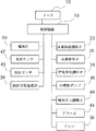
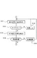
次に、実施例の燃料電池装置1の動作を説明する。図8は燃料電池装置1の動作を制御するときに関与する要素を示したブロック図である。図9は燃料電池装置1の制御を示すメインフローである。図8において、制御装置70及びメモリ73は燃料電池装置1のコントロールボックス(図1に示されていない)に収納されている。メモリ73にはコンピュータからなる制御装置70の動作を規定するコントロールプログラム及び各種制御を実行するときのパラメータやルックアップテーブルが収納されている。
【0047】
まず、図9のステップ1で実行される水素ガス供給系20の動作について説明する。起動時には、水素排気弁25を閉に保持しておいて、爆発限界以下の所定の濃度で水素ガスが燃料極13に供給されるように水素供給調圧弁23を調整する。排気弁25を閉じた状態で燃料電池装置1を運転すると、空気極より透過するN2、O2あるいは生成水の影響で燃料極13で消費される水素の分圧が徐々に低下するためこれに従って出力電圧も低下し、安定した電圧が得られなくなる。
【0048】
そこで、予め定められた規則に基づいて弁25を解放して水素分圧の低下したガスを排気し、燃料極13の雰囲気ガスをリフレッシュする。予め定められた規則はメモリ73に保存されており、弁25の開閉及び調圧弁23の調整は制御装置70が当該規則をメモリ73から読み出して実行する。
【0049】
この実施例では、電流計50で出力電流をモニタし、出力電流が所定の閾値を超えて低下したら所定の時間(例えば1秒間)弁25を解放する。あるいは弁25を閉とした状態で燃料電池装置1を運転したときに出力電圧が低下し始める時間間隔を予め計測しておき、その時間間隔と実質的に同一又は若干短い周期で弁25を解放するように、弁25を間欠的に開閉制御する。
【0050】
次に、図9のステップ3で実行される空気供給系30の動作について、図10を参照しながら説明する。ステップ31において燃料電池単位セル10Aから排出された直後の排気空気の温度を温度計39により検出する。その温度が80℃を超えていると(ステップ32)、燃料電池単位セル10Aが焼きつくおそれがあるので、ファン38の回転数を増やして風量を増大し(ステップ33)、もって熱発生源である空気極11の温度を下げる。このとき、当然ながら冷却ガス流路S2には80℃を超えた燃料電池単位セル10Aを冷却するのに必要な量の水が供給されているものとする。検出された温度が80℃以下の場合には、燃料電池単位セル10Aの負荷を検出する(ステップ34)。本実施例の場合は、図1の関係を制御に用いるので、空気極11と燃料極13の間の電流を検出する。制御装置70は電流計50で検出した電流値から電流密度を演算する。そして、制御装置70はその電流密度の値とステップ31で検出した温度とをメモリ73にテーブル形式で保存されている図1の関係に照らし合わせる。
【0051】
例えば、検出された温度と電流密度の関係が図1のAの条件であれば、風量を下げて、燃料電池単位セル10Aの運転状態を図1のBの条件に移行させる。即ち空気の供給量をストイキ比2に対応する量にまで下げて潜熱による冷却効果を低減させる。これにより、燃料電池単位セル10Aは出力(電流密度)を維持したまま、最も高い温度で運転されることとなる。なお、燃料電池単位セル10Aの温度を効率良く上げるためには、燃料電池単位セルが酸素不足にならないレベルで当初の風量をストイキ比2に対応するものよりも小さくして昇温速度を速め、条件Bの温度(ほぼ80℃)に近づいてきたところで、風量をストイキ比2に対応するものとすることが好ましい。なお、空気供給量(ストイキ比)と風量(ファン38の回転数)との関係が予めメモリ73に保存されており、制御装置70は求める空気供給量に対応した風量が得られるようファン38の回転数を制御する。ファン38には例えばサーボモータ駆動タイプが用いられる。
【0052】
条件Bで運転されていた燃料電池単位セル10Aの電流密度が0.7に変化したとすると、燃料電池単位セル10Aは条件Cで運転する必要がある。この場合は、風量を条件Cの風量(ストイキ比5に対応するところ)まで上げて燃料電池単位セル10Aの温度を条件Cの温度(ほぼ70℃)まで下げる。このように燃料電池単位セル10Aの運転温度はその運転可能領域において可能な限り高い温度とすることが好ましい。
【0053】
次に、図9のステップ5で実行される水供給系40の動作について説明する。タンク42の水がポンプ46で圧送される。そして、噴射圧力調整弁48でその圧力が調整されてノズル41から噴霧される。これにより、水が液体の状態(霧の状態)で冷却ガス流路S2に供給されることとなる。勿論、調圧弁48を省略して、ポンプ46に印加される電圧を調整しポンプ46の吐出圧力自体を制御し、もっとも所望の水量を得ることもできる。
【0054】
水の供給量は燃料電池単位セルの温度に応じて予め定められている。即ち、燃料電池単位セルをその温度に維持するために必要な最小量の水が供給される。ポンプ46による動力損をできる限り少なくするためである。なお、燃料電池単位セルが所定の温度(例えば30℃)以下になれば、水の供給を止めることもできる。燃料電池単位セル10Aの温度とそのときに供給すべき水量との関係はメモリ73に保存されている。この実施例では、図11に示すとおり、まず排出空気の温度が検出される(ステップ51)。そして、検出された温度に基づき最適水噴射量が演算される(ステップ53)。この演算はメモリ73に保存されていた関係を参照して行われる。
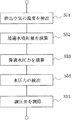
【0055】
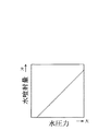
次に、ステップ55において最適水噴射量に対応する最適水圧力を演算する。例えば、水噴射量と水圧力とは図12に示す関係があるので、この関係が方程式若しくはルックアップテーブルのかたちでメモリ73に予め保存されている。この実施例では、ポンプ46を一定のパワーで運転しておいて循環路49の調圧弁48の開度によりノズル41の水圧力を調節している。即ち、調圧弁48の開度が大きく(小さく)なればノズル41の水圧力は小さく(大きく)なる。
【0056】
従って、ステップ54では水圧センサ47によりノズル41にかかる水圧力を検出し、フィードバック制御によりその水圧力が所望の値(最適水圧力)となるように調圧弁48を調節する(ステップ55)。
【0057】
その他、所定の時間経過(例えば5〜10秒)ごとに、一定の水圧で水供給系40を稼動させても良い。
また、水噴出量を一定に保っておいて単位セルの温度その他の運転状況に応じてそのオンオフ制御により水の供給量を制御することもできる。単位時間当たりの水噴出量と噴出時間との積算により総水噴出量が得られるので、ステップ53において求められた最適水噴射量が達成されるようにポンプを稼動させる。
潜熱によるスタックの冷却に必要な水を越えて水を供給してもスタックの冷却能力が低下するものではない。従って、ポンプのオン時には、最大風量(最大空気供給量)に対応した最大水供給量が常に供給されるようにしてもよい。
また、単位セルの温度が所定の温度(例えば30℃)以下の場合は、最低量の水を間欠的に噴射させるようにして、水供給装置にかかる不可をできるだけ小さくすることもできる。
【0058】
次に、実施例の燃料電池装置1の起動時の動作について説明する。図13に示すとおり、スイッチ(図示せず)がオンとなると(ステップ91)、ポンプ46をオンとする(ステップ93)。そして、所定の水噴射量となるように調圧弁48が調節されてノズル41より水が噴射される(ステップ95)。異常反応から燃料電池単位セル10Aを守るために空気極11へ噴射される水量は最大量とする。
【0059】
その後、空気供給系30をオンにする(ステップ97)。このときファン38の風量も最大として燃料電池単位セル10Aを冷却し、異常反応の防止を図る。引き続いて水素供給系20をオンにする(ステップ99)。空気極11と燃料極13との間に所望の出力が確認されたら、電力を外部に出力する。
【0060】
上記において、空気供給系30の稼動は水供給系40の稼動前であっても良い。また、水素供給系20の稼動の後に空気供給系30を稼動させても良い。ただし、水素供給系20を稼動させる前に水供給系40を稼動させる必要がある。空気供給系30の稼動の有無にかかわらず燃料電池単位セル10Aには空気が存在しているので、電解質膜12が乾燥した状態で水素を供給すると、異常燃焼の発生する可能性がある。つまり、この異常熱が発生した時、燃料電池単位セル10Aがダメージを被らないように、水素を供給する前に水を噴射して予め空気極11を濡らしておく。こうすることで、異常熱を水の蒸発熱に換え、更には電解質膜12の湿潤を促進して、燃料電池単位セル10Aのダメージを未然に防止する。
【0061】
次に、他の実施例を図14〜16に基づいて説明する。なお、既述の実施例で説明した要素及びステップには同一の参照番号を付してその説明を省略する。この実施例の燃料電池装置101では、ファン38の下流側にダンパ138が設けられる。ファン38を一定の回転数で駆動させておいてダンパ138を調節することにより空気供給量を変化させる。またこの実施例では温度計を燃料電池単位セル10Aに、好ましくは空気極側の集電部材に取付け、燃料電池単位セル10Aの温度を直接測定する。更にこの実施例では、車両用のアクセルの開度を検出し、検出した開度より燃料電池単位セル10Aへ次に要求される負荷を制御装置70が演算する(図16、ステップ134)。なお、このステップ134において、図1に関係が利用できるように、制御装置70は得られた負荷を更に電流密度に変換するものとする。
【0062】
この実施例によれば、燃料電池単位セルに要求される負荷をアクセルの状態から直接読み取るので、空気供給量をより迅速に制御できる。この実施例のほかの作用効果は前の実施例と同じである。
【0063】
【発明の効果】
このように構成された燃料電池装置によれば、セパレータ内に連通路が形成され、冷却ガス流路と空気流路が連通されているので、冷却ガス流路の空気がそのままの状態で、即ち温度及び蒸気量を維持した状態で、空気流路へ導入されることとなる。従って、燃料電池単位セルの空気極が乾燥することを確実に防止できる。このような冷却・加湿方式において、検出された運転状況に応じて、前記水供給装置による水の供給をオンオフ制御で行うとともに、前記空気供給手段による空気供給量の調整は空気流通量の増減で行うことにより、可及的に少量のエネルギーで水供給装置及び空気供給装置を駆動させ、効率よくスタックの温度調整及び空気流路へ必要な水分の供給をすることができる。
【0064】
この発明は、上記発明の実施の形態及び実施例の説明に何ら限定されるものではない。特許請求の範囲の記載を逸脱せず、当業者が容易に想定できる範囲で種々の変形態様もこの発明に含まれる。
【図面の簡単な説明】
【図1】燃料電池単位セルの電流密度(負荷)、空気排気温度(単位セル自体の温度)及びストイキ比(空気供給量)との関係を示すグラフである。
【図2】この発明の位置の実施例の燃料電池装置の構成を示す模式図である。
【図3】本発明に適用される単電池の部分横断面図である。
【図4】本発明に適用されるセパレータの縦断面図である。
【図5】本発明に適用されるセパレータの分解斜視図である。
【図6】本発明に適用されるセパレータを下方から見た排出規制手段の構成を示す部分横断面図である。
【図7】本発明に適用されるセパレータによる冷却と排水のメカニズムを示す模式図である。
【図8】同じく燃料電池装置の制御系を示す模式図である。
【図9】同じく燃料電池装置の動作を示すメインフローである。
【図10】同じく空気供給系の動作を示すフローチャートである。
【図11】同じく水供給系の動作を示すフローチャートである。
【図12】同じく水噴射量と水圧力の関係を示すグラフ図である。
【図13】同じく起動時の制御を示すフローチャートである。
【図14】この発明の他の実施例の燃料電池装置の構成を示す模式図である
【図15】同じく制御系を示す模式図である。
【図16】同じく空気供給系の動作を示すフローチャートである。
【符号の説明】
1、101 燃料電池装置
10A 燃料電池単位セル
10B セパレータ
11 空気極
30 空気供給系
38 ファン
39、139 温度計
40 水供給系
50 アンペアメータ
143 連通孔
S1 空気流路
S2 冷却ガス流路
S3 燃料ガス流路[0001]
TECHNICAL FIELD OF THE INVENTION
The present invention relates to a fuel cell device, and more particularly to an improvement of a so-called PEM type fuel cell device having a polymer solid electrolyte membrane.
[0002]
[Prior art]
A battery unit cell of a PEM type fuel cell device has a fuel electrode (also referred to as a hydrogen electrode when hydrogen is used as a fuel electrode) and an air electrode (also referred to as an oxygen electrode because oxygen is a reaction gas and also referred to as an oxidation electrode). And a solid polymer electrolyte membrane sandwiched between the two. A reaction layer containing a catalyst is interposed between the air electrode and the electrolyte membrane.
[0003]
In the electromotive force of the fuel cell having such a configuration, as a result of the fuel gas being supplied to the fuel electrode side (anode) and the oxidizing gas being supplied to the air electrode side, electrons are generated with the progress of the electrochemical reaction. It is generated by extracting electrons to an external circuit. That is, the hydrogen ions obtained at the fuel electrode (anode) move in the electrolyte membrane containing water to the air electrode (cathode) side in the form of protons (H 30 + ), The obtained electrons move to the air electrode (cathode) side through an external load and react with oxygen in the oxidizing gas (including air) to purify water, extracting electrical energy by a series of electrochemical reactions. (For example, see Patent Document 1).
[0004]
Since a sufficient power cannot be obtained by such a unit cell of the fuel cell alone, a so-called stack in which many unit cells are stacked in series is used. In this stack, since the unit cells are closely stacked, it is necessary to prevent overheating. Therefore, conventionally, a cooling board was incorporated in the stack, and the cooling was performed by water cooling or air cooling.
In
According to such a fuel cell device, the stack can be efficiently cooled with a simple configuration, a high output density can be accommodated, and a lightweight and low-cost cooling means is provided.
See also
[0005]
[Patent Document 1]
Japanese Patent Application Laid-Open No. 2002-15760 [Patent Document 2]
JP 10-247505 A [Patent Document 3]
JP 2001-332278 A
[Problems to be solved by the invention]
According to the fuel cell device described in
Therefore, an object of the present invention is to provide a fuel cell device including a separator having a novel configuration and an appropriate operation method of the fuel cell device.
[0007]
[Means for Solving the Problems]
The present invention has been made to solve the above problems. That is,
A unit cell of a pair of fuel cells,
A separator that is arranged between the unit cells and forms an air flow path with the one unit cell, and forms a fuel gas flow path with the other unit cell, wherein the cooling gas flow path is formed. A separator, wherein a peripheral wall of the cooling gas flow path is thermally connected to the unit cell,
A water supply device that supplies water in a liquid state to the cooling gas flow path of the separator,
An air supply device that supplies air to the cooling gas flow path,
In a fuel cell device comprising:
The separator is formed with a communication path that communicates the cooling gas flow path and the air flow path,
An operation status detection device that detects an operation status of the unit cell is provided,
According to the detected operating condition, the water supply by the water supply unit is performed by on / off control, and the air supply amount by the air supply device is adjusted by increasing or decreasing the air flow amount. apparatus.
[0008]
According to the fuel cell device configured as described above, the communication path is formed in the separator, and the cooling gas flow path and the air flow path are communicated with each other. The air is introduced into the air flow path while maintaining the temperature and the amount of steam. Therefore, it is possible to reliably prevent the air electrode of the fuel cell unit from drying. In such a cooling / humidifying system, the supply of water by the water supply device is performed by on / off control in accordance with the detected operation state, and the adjustment of the air supply amount by the air supply means is performed by increasing or decreasing the air circulation amount. By doing so, it is possible to drive the water supply device and the air supply device with as little energy as possible, and to efficiently control the temperature of the stack and supply necessary moisture to the air flow path.
[0009]
In the above, a general-purpose unit cell can be used. It is not necessary to dispose the specified separator between all the unit cells in the stack.
The heat of the unit cell and the air to which water as the cooling gas is added are heat-exchanged at the peripheral wall of the cooling gas flow path. Therefore, it is preferable that the peripheral wall of the cooling gas flow path is formed of a material having high thermal conductivity in contact with each of the pair of unit cells. Of course, the heat of the unit cell may be conducted to the peripheral wall of the cooling gas passage by another member.
The communication path is not particularly limited as long as it can be sent to the air flow path while maintaining the temperature and humidity of the gas components (air and water vapor) in the cooling gas flow path in the cell. It is preferable to form a through hole that penetrates a wall part that separates the air passage from the air passage. This simplifies the configuration of the communication path and, consequently, the configuration of the separator, and makes it possible to provide an inexpensive fuel cell device.
For example, a fan can be used as the air supply device. In the present invention, the supply of air is always on, and the supply amount is controlled to increase or decrease. Here, if air is substantially supplied to the cooling gas flow path under the influence of the ram wind or other wind, and the air is supplied to the air flow path through the communication path, a fan as an air supply device is used. You can stop it.
It is preferable that the fan is capable of linearly changing the air flow, that is, the air supply amount. Thereby, the temperature of the stack can be adjusted more precisely.
[0010]
According to the fuel cell device configured as described above, first, the air into which the water is injected and mixed in the air manifold is supplied from the cooling gas flow path formed in the separator to the air flow path through the communication path. Suggesting things. In this method, the unit cells are cooled by the latent heat of the water that evaporates due to the heat of the unit cells transmitted to the peripheral wall of the cooling gas flow path, and the vaporized water is supplied to the air flow path together with the air. Thereby, while cooling the unit cell via the separator, the blockage of the flow path due to the intrusion of liquid water or mist-like water into the air flow path is prevented. That is, in the case of the fuel cell device having the above-described mechanism, the air and water supplied to the cooling gas flow path are used for latent heat cooling of the heat generated during power generation of the fuel cell. Then, a part of the water supplied in a liquid state evaporates in the cooling gas flow path, and is supplied as water vapor from the communication path to the air flow path together with the air.The air is used for the reaction of the fuel cell, and the water vapor is humidified. Used for
[0011]
Secondly, since the supply amount of air is variable, by changing the supply amount of air to an optimum amount, cooling utilizing the latent heat of water supplied to the cooling passage is sufficient and efficient. Well done. As a result, the separator and thus the fuel cell unit cells are efficiently cooled. In addition, as a means for efficiently using the latent heat of water, it is preferable that the particle size of water is 50 μm to 500 μm. The thickness of the electrolyte membrane of the fuel cell unit cell is desirably 200 μm or less. That is, when the temperature of the fuel cell is operated at a high temperature and it is desired to lower the temperature, the amount of air supplied (the amount of air blown, the amount of air supplied per unit time, The amount of air passing through the cooling gas passage S2 and the air passage S1 (see FIG. 7) per time is increased. In the type in which the air supply amount is fixed, a large amount of water needs to be supplied because the sensible heat of water is used, and thus there are various problems. However, even if the air supply amount is increased, the problem hardly occurs. This is because even if the air supply amount is increased, the load applied to the air supply device (such as a fan) is negligibly smaller than the load applied when the amount of water is increased. When the fuel cell is operated at a low temperature and it is desired to increase the temperature of the fuel cell, the air flow is reduced so that the air supply is not excessive. As a result, the temperature of the fuel cell can be reliably increased, and the power consumed by the air supply device is reduced as much as possible, thereby reducing power loss. In addition, the capacity of the condenser for water recycling can be reduced because the internal temperature increases and the temperature difference with the outside air increases.
[0012]
Further, according to the present invention, the supply of liquid water is controlled on / off in accordance with an operating condition such as an operating temperature of the fuel cell. By providing an off time for the supply of water, it is possible to prevent an excessive supply of water and reduce the power consumption of the liquid supply device as much as possible. Since control is performed by turning on and off, even if a large amount of water is injected at the time of turning on, the average amount of water absorbed per unit time can be controlled to be constant by adjusting the time of turning off. By injecting a large amount of water at the time of ON, water can be uniformly and reliably supplied to the cooling space. As described above, by controlling the amount of air blown and / or the amount of liquid supplied, the operating condition (operating temperature) of the fuel cell unit cell can be kept within a predetermined range.
A liquid such as alcohol can be used instead of or in combination with water.
[0013]
According to the present invention, since the supply amount of air and the supply amount of water are independent, the required supply amount of air and water can be reduced at a required timing as compared with a supply system in which they are not independent. Can be controlled independently. As a result, a high output of the fuel cell can be obtained efficiently without waste. Further, since the amount of air and water to be recovered can be minimized, the size of the condenser can be reduced, and power consumption by auxiliary equipment can be saved. In addition, the time required for activation can be reduced.
[0014]
FIG. 1 shows the theoretical relationship between the load (current density) and the temperature (air exhaust temperature) of the fuel cell at each stoichiometric ratio. Here, the stoichiometric ratio defines the amount of air supplied to the air electrode based on the amount of air including the theoretical amount of oxygen consumed in the fuel cell reaction. Therefore, when the stoichiometric ratio is 1, the minimum amount of air theoretically necessary is sent, and when the stoichiometric ratio is 2, the air supply amount is twice as large as when the stoichiometric ratio is 1. FIG. 1 shows that the fuel cell can be operated at a higher temperature to obtain the same load as the stoichiometric ratio is smaller, that is, the air supply amount is smaller. The higher the operating temperature of the fuel cell, the higher the efficiency. In addition, the temperature of the discharged air is increased by the high-temperature operation, so that the capacity of the condenser can be reduced. Therefore, it is preferable to operate the fuel cell unit cell at the highest temperature that can meet the required load. Since the load and the temperature of the fuel cell are uniquely determined by the stoichiometric ratio, if one of the load and the temperature is detected and the stoichiometric ratio, that is, the air supply amount (strictly speaking, the supply amount at the air passage inlet) is determined. It will be good.
[0015]
However, current fuel cells have various restrictions on the operating temperature and the stoichiometric ratio (air supply amount). For example, in order to reliably prevent seizure of a fuel cell unit cell, its operating temperature needs to be, for example, 100 to 80 ° C. or lower. Further, according to the study of the present inventors, it was impossible to operate under the condition above the broken line L shown in FIG. This is presumed to be because when the air supply amount is small (when the air volume is small), the air does not reach the air electrode sufficiently due to the resistance of the air supply path and the gas diffusion layer, the ability of the catalyst, and the like. Therefore, in FIG. 1, the fuel cell can operate in a region below 80 ° C. and below the broken line L, for example. Then, in consideration of the efficiency, it is preferable to operate at the highest temperature side of the operable region.
[0016]
2. Description of the Related Art In a fuel cell device for a vehicle in which a load fluctuates greatly, an air supply amount is changed according to a required load. At this time, it is preferable to simultaneously detect the temperature of the fuel cell and adjust the air supply amount so that the maximum temperature at which the required load can be realized, that is, the minimum stoichiometric ratio (air supply amount). On the other hand, in a fuel cell device used in an environment in which the load hardly fluctuates, substantially only the temperature of the fuel cell is monitored, and only when the temperature fluctuates, the air supply amount is adjusted so that the temperature becomes a desired temperature. Just adjust it. That is, when the temperature of the fuel cell becomes lower than the desired temperature range, the air supply amount is reduced to reduce the cooling effect using the latent heat of water, while the temperature of the fuel cell becomes higher than the desired temperature range. In this case, the air supply amount is increased to enhance the cooling effect using the latent heat of water. Various restrictions are imposed on the operating conditions of the fuel cell device depending on the external environment and the performance of auxiliary equipment. In some cases, the operating conditions of the fuel cell may be limited to a region indicated by a square in the operable condition region in FIG. In this region, the operating temperature of the fuel cell does not exceed the
[0017]
In any of the above cases, it is assumed that a sufficient amount of water is always supplied to the cooling channel. That is, it is assumed that, even if there is one that evaporates due to the heat of the fuel cell, liquid water is always present in the air electrode and its surroundings (that is, in the air flow path) during operation of the fuel cell device. . Thus, it is assumed that water is always present in the cooling gas passage and the air passage. As described above, since the water is always present at the air electrode, the latent heat of the water can be efficiently used. As a result, the cooling plate can be thinned out from the fuel cell stack or omitted. It is preferable to provide a cooling plate, a cooling pipe, or other cooling devices in the fuel cell stack in consideration of a case where a sufficient amount of water may not be ensured. The heat of the stack is taken out to the outside by the heat medium (usually water) flowing to the cooling device, and can be used for heating the interior of the vehicle. (Used as so-called cogeneration).
[0018]
In the above, air is supplied without being compressed substantially. The present invention can be applied to a fuel cell device of a type having a pressurized oxidizing gas supply system. The pressurized oxidizing gas supply system includes not only the case where the oxidizing gas supply system is provided with the oxidizing gas compressor but also the case where the pressure inside the system becomes higher than the atmospheric pressure due to the resistance of the gas pipe. The temperature of the fuel cell can of course be measured by attaching a thermometer to the unit cell of the fuel cell, but as shown in FIG. 1, the temperature is measured indirectly by measuring the temperature of the exhaust air. It is also possible. In this case, it is preferable to measure the temperature of the air immediately after being discharged from the fuel cell. The load of the fuel cell is the product of the current and voltage between both poles of the fuel cell unit cell. As a parameter to be referred to when controlling the air supply amount, it is possible to detect the current load that is reliably output from the fuel cell unit cell and use this. In addition, a load required next to the fuel cell, for example, a speed, a torque, or an accelerator opening may be detected and used as the parameter.
[0019]
【Example】
Next, an embodiment of the present invention will be described. FIG. 2 shows a schematic configuration of the
[0020]
First, the fuel cell stack will be described. The unit unit of the fuel
[0021]
It is preferable that the nozzle injects water directly toward the cooling gas flow path inlet. Thus, a desired amount of water can be supplied to the cooling gas flow path regardless of the air supply amount. That is, the supply amount of air and the supply amount of water can be controlled independently. In addition, a desired amount of water can be reliably supplied into the cooling gas passage even in a state of a large air supply amount (air volume) such as at the time of starting. Therefore, the start-up time can be reduced. The change in the air supply and the change in the water supply are not always required at the same time, but may need to be changed independently. For example, if only the supply amount of air needs to be changed, and even the supply amount of water is changed, the response of control of the fuel cell unit cell is slowed, which may result in a decrease in output of the fuel cell device. is there. On the other hand, in the present invention, a required amount of water and / or air can be supplied at a required timing, so that the fuel cell can be efficiently controlled. Further, by independently controlling the supply of water and air, it is possible to avoid supply of useless air and useless water. Also in this respect, the operation of the fuel cell becomes efficient. Furthermore, the capacity of the condenser can be reduced by avoiding the supply of useless water and useless air.
[0022]
Next, the hydrogen gas supply system will be described. In this embodiment, a hydrogen cylinder composed of a high-pressure tank was used as the
[0023]
The exhaust gas from the fuel gas passage S3 is discharged to the outside air. This exhaust gas can be supplied to an air manifold, where it can be mixed with air.
[0024]
Next, the air supply system will be described. Air is supplied to the air flow path S1 from the cooling gas flow path S2 via the
[0025]
The water separated by the
[0026]
Next, the water supply system will be described. In the
[0027]
Further, a measuring instrument arranged in the fuel cell device will be described.
[0028]
The above-described fuel cell stack is configured by stacking a large number of plate-shaped
[0029]
Next, a detailed configuration of the
[0030]
One
[0031]
The other current collecting
[0032]
The
[0033]
The
[0034]
The
[0035]
Further, a detailed configuration not shown in the drawings will be described. Preferably, the cross-sectional area of the flow path constituting the cooling gas flow path S2 is set to be gradually reduced from the upper side to the lower side. By employing such a configuration, the pressure loss of the air flowing from the cooling gas passage S1 to the air passage S2 can be reduced. Such a flow path configuration can be realized by appropriately setting the height and / or width of the
[0036]
Further, the inner wall surfaces of the air flow path S1 and the cooling gas flow path S2 are subjected to a hydrophilic treatment as necessary. Specifically, this treatment is performed such that the contact angle between the inner wall surface and water is 40 ° or less, preferably 30 ° or less. As a treatment method, a method of applying a hydrophilic treatment agent to the surface is employed. Examples of the treatment agent to be applied include polyacrylamide, polyurethane resin, titanium oxide (TiO2), and the like. As another hydrophilic treatment, a treatment for roughening the roughness of the metal surface may be mentioned. For example, plasma processing is an example. The hydrophilic treatment is preferably performed on a portion where the temperature is highest. For example, the cooling gas flow path inner wall surface F1 on the back side of the top 142 of the
[0037]
The
[0038]
Further, as in the cross section of the lower part of the unit cell shown in FIG. 6, the discharge portion of the cooling gas flow path S2 is provided with a discharge regulating means for slowly discharging the liquid water accumulated in the discharge portion. This discharge restricting means seals the discharge portion with liquid water to prevent discharge of air. In this embodiment, the discharge restricting means is a flow passage narrowing portion S2 'in which the cross-sectional area of the flow passage forming the discharge portion of the cooling gas flow passage S2 is narrowed over a predetermined length. The flow path constricted portion S2 ′ shown in the drawing is formed by pressing the
[0039]
The fuel cell stack having such a configuration operates as schematically shown in FIG. 7 by supplying air, water, and hydrogen to each unit cell. According to such a fuel cell device, the air flow path S1 and the cooling gas flow path S2 in the fuel cell stack can be arranged in a unified distribution path, and air and water can be distributed at the same time. There is no need to provide a separate device. When such unit cells are stacked, the air and water are uniformly supplied from the upper surface of the stack, so that the opening of the air flow path S1 is formed so that water does not directly enter the air flow path S1. It is assumed that the
[0040]
On the other hand, the air and water that have not entered the air flow path S1 are discharged from the lower opening of the cooling gas flow path S2 below the fuel cell stack as it is, but the flow path constriction portion according to the present invention. By the action of S2 ', the water in the liquid water state flowing down the wall reaches the channel narrowing portion and stays there, thereby causing a phenomenon of blocking the channel by the capillary phenomenon, and this water generates air from the cooling gas channel S2. Acts to prevent direct discharge of Therefore, substantially all of the air supplied to the cooling gas passage S2 is sent to the air passage S1, and then discharged from the fuel cell stack via the air passage.
[0041]
On the other hand, the supply of hydrogen to the fuel flow path S3 is performed by using one of the hydrogen flow paths L1 and L2 (see FIG. 3) penetrating both sides of each
[0042]
Due to the above-described operation, in the case of this embodiment, since the mist-like water droplets do not enter the air flow path S1 as it is on the air flow, an extremely thin air flow path S1 formed by pressing. This also provides an advantage that the flow of the air stream is not obstructed by water droplets. Further, the air flow path S1 and the cooling gas flow path S2 are alternately arranged in parallel along the electrode surface, and are adjacent to each other with the side wall of the
[0043]
By the way, when the
[0044]
Further, in this embodiment, the air and water flowing from the upper opening of the
[0045]
The
[0046]
Next, the operation of the
[0047]
First, the operation of the hydrogen
[0048]
Therefore, the
[0049]
In this embodiment, the output current is monitored by the
[0050]
Next, the operation of the
[0051]
For example, if the relationship between the detected temperature and the current density is the condition shown in FIG. 1A, the air flow is reduced, and the operating state of the fuel
[0052]
Assuming that the current density of the fuel
[0053]
Next, the operation of the
[0054]
The supply amount of water is determined in advance according to the temperature of the unit cell of the fuel cell. That is, the minimum amount of water required to maintain the fuel cell unit cell at that temperature is supplied. This is to minimize power loss caused by the
[0055]
Next, at
[0056]
Therefore, in step 54, the water pressure applied to the
[0057]
In addition, the
In addition, it is also possible to control the supply amount of water by controlling the on / off control of the unit cell in accordance with the temperature of the unit cell and other operating conditions while keeping the water ejection amount constant. Since the total water ejection amount is obtained by integrating the water ejection amount per unit time and the ejection time, the pump is operated so that the optimum water injection amount obtained in
Supplying water beyond the water required for cooling the stack by latent heat does not reduce the cooling capacity of the stack. Therefore, when the pump is turned on, the maximum water supply amount corresponding to the maximum air volume (maximum air supply amount) may always be supplied.
When the temperature of the unit cell is equal to or lower than a predetermined temperature (for example, 30 ° C.), the minimum amount of water can be intermittently sprayed to minimize the possibility of the water supply device.
[0058]
Next, the operation of the
[0059]
Thereafter, the
[0060]
In the above, the operation of the
[0061]
Next, another embodiment will be described with reference to FIGS. Note that the same reference numerals are given to the elements and steps described in the above-described embodiments, and description thereof will be omitted. In the
[0062]
According to this embodiment, since the load required for the fuel cell unit cell is directly read from the state of the accelerator, the air supply amount can be controlled more quickly. Other functions and effects of this embodiment are the same as those of the previous embodiment.
[0063]
【The invention's effect】
According to the fuel cell device configured as described above, the communication path is formed in the separator, and the cooling gas flow path and the air flow path are communicated with each other. The air is introduced into the air flow path while maintaining the temperature and the amount of steam. Therefore, it is possible to reliably prevent the air electrode of the fuel cell unit from drying. In such a cooling and humidifying system, the supply of water by the water supply device is performed by on / off control according to the detected operating condition, and the adjustment of the air supply amount by the air supply unit is performed by increasing or decreasing the air circulation amount. By doing so, it is possible to drive the water supply device and the air supply device with as little energy as possible, and to efficiently control the temperature of the stack and supply necessary moisture to the air flow path.
[0064]
The present invention is not limited to the description of the embodiment and the example of the above invention. Various modifications are included in the present invention without departing from the scope of the claims and within the scope of those skilled in the art.
[Brief description of the drawings]
FIG. 1 is a graph showing a relationship among a current density (load) of a fuel cell unit cell, an air exhaust temperature (temperature of the unit cell itself), and a stoichiometric ratio (air supply amount).
FIG. 2 is a schematic diagram showing a configuration of a fuel cell device according to an embodiment of the present invention.
FIG. 3 is a partial cross-sectional view of a unit cell applied to the present invention.
FIG. 4 is a longitudinal sectional view of a separator applied to the present invention.
FIG. 5 is an exploded perspective view of a separator applied to the present invention.
FIG. 6 is a partial cross-sectional view showing a configuration of a discharge restricting unit as viewed from below a separator applied to the present invention.
FIG. 7 is a schematic view showing a mechanism of cooling and draining by a separator applied to the present invention.
FIG. 8 is a schematic diagram showing a control system of the fuel cell device.
FIG. 9 is a main flow showing the operation of the fuel cell device.
FIG. 10 is a flowchart showing the operation of the air supply system.
FIG. 11 is a flowchart showing the operation of the water supply system.
FIG. 12 is a graph showing the relationship between the water injection amount and the water pressure.
FIG. 13 is a flowchart showing control at the time of activation.
FIG. 14 is a schematic diagram showing a configuration of a fuel cell device according to another embodiment of the present invention. FIG. 15 is a schematic diagram showing a control system.
FIG. 16 is a flowchart showing the operation of the air supply system.
[Explanation of symbols]
1, 101
Claims (18)
該単位セル間に配置されて前記一方の単位セルとの間に空気流路を形成し、前記他方の単位セルとの間に燃料ガス流路を形成するセパレータであって、冷却ガス流路を備え、該冷却ガス流路の周壁が前記単位セルと熱的に連結されているセパレータと、
前記セパレータの冷却ガス流路へ水を液体の状態で供給する水供給装置と、
前記冷却ガス流路へ空気を供給する空気供給装置と、
を備える燃料電池装置において、
前記セパレータには前記冷却ガス流路と前記空気流路とを連通する連通路が形成され、
前記単位セルの運転状況を検出する運転状況検出装置が備えられ、
検出された運転状況に応じて、前記水供給手段による水の供給をオンオフ制御で行うとともに、前記空気供給装置による空気供給量の調整は空気流通量の増減で行う、ことを特徴とする燃料電池装置。A unit cell of a pair of fuel cells,
A separator that is arranged between the unit cells and forms an air flow path with the one unit cell, and forms a fuel gas flow path with the other unit cell, wherein the cooling gas flow path is formed. A separator, wherein a peripheral wall of the cooling gas flow path is thermally connected to the unit cell,
A water supply device that supplies water in a liquid state to the cooling gas flow path of the separator,
An air supply device that supplies air to the cooling gas flow path,
In a fuel cell device comprising:
The separator is formed with a communication path that communicates the cooling gas flow path and the air flow path,
An operation status detection device that detects an operation status of the unit cell is provided,
A fuel cell, wherein the supply of water by the water supply means is performed by on / off control in accordance with the detected operation state, and the adjustment of the amount of air supplied by the air supply device is performed by increasing or decreasing the amount of air circulation. apparatus.
該単位セル間に配置されて前記一方の単位セルとの間に空気流路を形成し、前記他方の単位セルとの間に燃料ガス流路を形成するセパレータであって、冷却ガス流路を備え、該冷却ガス流路の周壁が前記単位セルと熱的に連結されているセパレータと、
前記セパレータの冷却ガス流路へ水を液体の状態で供給する水供給装置と、
前記冷却ガス流路へ空気を供給する空気供給装置と、
を備える燃料電池装置において、
前記セパレータには前記冷却ガス流路と前記空気流路とを連通する連通路が形成され、
前記単位セルの運転温度を検出する運転温度検出装置と、
検出された運転温度が所定値以上の場合に前記水を供給し、前記所定値未満の場合に水の供給を停止し、
検出された運転温度に対応して空気の供給量を増減する、ことを特徴とする燃料電池装置。A unit cell of a pair of fuel cells,
A separator that is arranged between the unit cells and forms an air flow path with the one unit cell, and forms a fuel gas flow path with the other unit cell, wherein the cooling gas flow path is formed. A separator, wherein a peripheral wall of the cooling gas flow path is thermally connected to the unit cell,
A water supply device that supplies water in a liquid state to the cooling gas flow path of the separator,
An air supply device that supplies air to the cooling gas flow path,
In a fuel cell device comprising:
The separator is formed with a communication path that communicates the cooling gas flow path and the air flow path,
An operating temperature detecting device for detecting an operating temperature of the unit cell,
Supplying the water when the detected operating temperature is equal to or higher than a predetermined value, and stopping the supply of water when the detected operating temperature is lower than the predetermined value,
A fuel cell device, wherein the supply amount of air is increased or decreased in accordance with a detected operating temperature.
前記冷却ガス流路へ空気を供給する送風装置であって、該空気の供給量を調整可能な送風装置と、
該空気供給手段とは独立して制御されて前記冷却ガス流路へ水を液体の状態で供給する水供給装置であって、水の供給量をオンオフ制御する水供給装置と、を備える燃料電池装置。A separator connected to a unit cell of the fuel cell to form an air flow path between the unit cell and the separator, the separator being shared by the cooling gas flow path and the cooling gas flow path and the air flow path. A separator provided with a first wall, wherein the first wall is provided with a transfer unit that transfers a gas component of the cooling gas flow path to the air flow path;
A blower that supplies air to the cooling gas flow path, and a blower that can adjust a supply amount of the air,
A water supply device controlled independently of the air supply means to supply water to the cooling gas flow path in a liquid state, wherein the water supply device controls on / off of a supply amount of water. apparatus.
該単位セル間に配置されて前記一方の単位セルとの間に空気流路を形成し、前記他方の単位セルとの間に燃料ガス流路を形成するセパレータであって、冷却ガス流路を備え、該冷却ガス流路の周壁が前記単位セルと熱的に連結され、前記冷却ガス流路と前記空気流路とを連通する連通路が形成されているセパレータと、を備え、
前記セパレータの冷却ガス流路へ空気と液体状の水を供給して、前記単位セルを冷却する燃料電池装置を運転する方法であって、
前記単位セルの運転状況を検出し、検出された運転状況に応じて水の供給をオンオフで行うとともに、空気は常に供給しつつその増減を行う、ことを特徴とする燃料電池装置の運転方法。A unit cell of a pair of fuel cells,
A separator that is arranged between the unit cells and forms an air flow path with the one unit cell, and forms a fuel gas flow path with the other unit cell, wherein the cooling gas flow path is formed. A peripheral wall of the cooling gas flow path is thermally connected to the unit cell, and a separator having a communication path communicating the cooling gas flow path and the air flow path is provided.
A method of operating a fuel cell device that cools the unit cells by supplying air and liquid water to a cooling gas flow path of the separator,
A method of operating a fuel cell device, comprising: detecting an operation state of the unit cell; turning on and off water in accordance with the detected operation state; and constantly increasing and decreasing air supply.
該単位セル間に配置されて前記一方の単位セルとの間に空気流路を形成し、前記他方の単位セルとの間に燃料ガス流路を形成するセパレータであって、冷却ガス流路を備え、該冷却ガス流路の周壁が前記単位セルと熱的に連結され、前記冷却ガス流路と前記空気流路とを連通する連通路が形成されているセパレータと、を備え、
前記セパレータの冷却ガス流路へ空気と液体状の水を供給して、前記単位セルを冷却する燃料電池装置を運転する方法であって、
前記単位セルの運転温度を検出し、検出された運転温度が所定値以上の場合に水を供給し、前記所定値未満の場合に水の供給を停止し、検出された運転温度に対応して空気の供給量を増減する、ことを特徴とする燃料電池装置の運転方法。A unit cell of a pair of fuel cells,
A separator that is arranged between the unit cells and forms an air flow path with the one unit cell, and forms a fuel gas flow path with the other unit cell, wherein the cooling gas flow path is formed. A peripheral wall of the cooling gas flow path is thermally connected to the unit cell, and a separator having a communication path communicating the cooling gas flow path and the air flow path is provided.
A method of operating a fuel cell device that cools the unit cells by supplying air and liquid water to a cooling gas flow path of the separator,
Detecting the operating temperature of the unit cell, supplying water when the detected operating temperature is equal to or higher than a predetermined value, stopping the supply of water when the detected operating temperature is lower than the predetermined value, corresponding to the detected operating temperature. A method for operating a fuel cell device, comprising: increasing or decreasing a supply amount of air.
Priority Applications (1)
| Application Number | Priority Date | Filing Date | Title |
|---|---|---|---|
| JP2002360700A JP2004192995A (en) | 2002-12-12 | 2002-12-12 | Fuel cell device |
Applications Claiming Priority (1)
| Application Number | Priority Date | Filing Date | Title |
|---|---|---|---|
| JP2002360700A JP2004192995A (en) | 2002-12-12 | 2002-12-12 | Fuel cell device |
Publications (1)
| Publication Number | Publication Date |
|---|---|
| JP2004192995A true JP2004192995A (en) | 2004-07-08 |
Family
ID=32759709
Family Applications (1)
| Application Number | Title | Priority Date | Filing Date |
|---|---|---|---|
| JP2002360700A Pending JP2004192995A (en) | 2002-12-12 | 2002-12-12 | Fuel cell device |
Country Status (1)
| Country | Link |
|---|---|
| JP (1) | JP2004192995A (en) |
Cited By (6)
| Publication number | Priority date | Publication date | Assignee | Title |
|---|---|---|---|---|
| JP2006318715A (en) * | 2005-05-11 | 2006-11-24 | Nec Corp | Polymer electrolyte fuel cell and operation method of polymer electrolyte fuel cell |
| JP2008004310A (en) * | 2006-06-20 | 2008-01-10 | Nissan Motor Co Ltd | Temperature control method and temperature control device for fuel cell |
| JP2009506484A (en) * | 2005-08-26 | 2009-02-12 | ビーワイディー カンパニー リミテッド | Flow field plates for fuel cells |
| JP2015521353A (en) * | 2012-05-28 | 2015-07-27 | インテリジェント エナジー リミテッドIntelligent Energy Limited | Bipolar plate for fuel cell |
| US9806361B2 (en) | 2012-05-28 | 2017-10-31 | Intelligent Energy Limited | Fuel cell plate assemblies |
| JP2017199609A (en) * | 2016-04-28 | 2017-11-02 | トヨタ自動車株式会社 | Fuel cell |
-
2002
- 2002-12-12 JP JP2002360700A patent/JP2004192995A/en active Pending
Cited By (6)
| Publication number | Priority date | Publication date | Assignee | Title |
|---|---|---|---|---|
| JP2006318715A (en) * | 2005-05-11 | 2006-11-24 | Nec Corp | Polymer electrolyte fuel cell and operation method of polymer electrolyte fuel cell |
| JP2009506484A (en) * | 2005-08-26 | 2009-02-12 | ビーワイディー カンパニー リミテッド | Flow field plates for fuel cells |
| JP2008004310A (en) * | 2006-06-20 | 2008-01-10 | Nissan Motor Co Ltd | Temperature control method and temperature control device for fuel cell |
| JP2015521353A (en) * | 2012-05-28 | 2015-07-27 | インテリジェント エナジー リミテッドIntelligent Energy Limited | Bipolar plate for fuel cell |
| US9806361B2 (en) | 2012-05-28 | 2017-10-31 | Intelligent Energy Limited | Fuel cell plate assemblies |
| JP2017199609A (en) * | 2016-04-28 | 2017-11-02 | トヨタ自動車株式会社 | Fuel cell |
Similar Documents
| Publication | Publication Date | Title |
|---|---|---|
| JP3077618B2 (en) | Solid polymer electrolyte fuel cell | |
| JP4085652B2 (en) | Fuel cell | |
| JP3203150B2 (en) | Polymer electrolyte fuel cell and polymer electrolyte fuel cell system | |
| US20010051292A1 (en) | Method of cooling a fuel cell | |
| JPH11317235A (en) | Water direct injection fuel cell system | |
| US7267900B2 (en) | Fuel cell system | |
| JP4686814B2 (en) | Fuel cell device | |
| US20050244689A1 (en) | Separator and fuel cell system using that separator | |
| US20020071981A1 (en) | Fuel cell | |
| JPH09180743A (en) | Polymer electrolyte fuel cell | |
| JP2004192996A (en) | Fuel cell device | |
| JPH11242962A (en) | Fuel cell device | |
| JP2010129482A (en) | Fuel cell separator, fuel cell stack, and fuel cell system | |
| JP4552236B2 (en) | Fuel cell device | |
| JP2004192994A (en) | Fuel cell device | |
| JP2000277128A (en) | Polymer electrolyte fuel cell | |
| JPH1064569A (en) | Solid polymer electrolyte fuel cell | |
| JP4815916B2 (en) | Fuel cell and fuel cell system | |
| JP4501165B2 (en) | Fuel cell system for vehicles | |
| JP2005340179A (en) | Separator and fuel cell device using the same | |
| JP2004185938A (en) | Fuel cell and fuel cell system | |
| JP2003272666A (en) | Fuel cell | |
| JP4147781B2 (en) | Fuel cell separator and fuel cell system | |
| JP4686813B2 (en) | Fuel cell device | |
| JP4214045B2 (en) | Fuel cell system and fuel cell stack |