JP2004196366A - Fueling system - Google Patents
Fueling system Download PDFInfo
- Publication number
- JP2004196366A JP2004196366A JP2002367597A JP2002367597A JP2004196366A JP 2004196366 A JP2004196366 A JP 2004196366A JP 2002367597 A JP2002367597 A JP 2002367597A JP 2002367597 A JP2002367597 A JP 2002367597A JP 2004196366 A JP2004196366 A JP 2004196366A
- Authority
- JP
- Japan
- Prior art keywords
- oil
- oil pump
- pump
- pumps
- nozzle
- Prior art date
- Legal status (The legal status is an assumption and is not a legal conclusion. Google has not performed a legal analysis and makes no representation as to the accuracy of the status listed.)
- Granted
Links
- 239000003921 oil Substances 0.000 claims abstract description 165
- 239000000295 fuel oil Substances 0.000 claims abstract description 29
- 238000005303 weighing Methods 0.000 claims abstract description 16
- 238000005259 measurement Methods 0.000 claims description 5
- 239000000446 fuel Substances 0.000 claims description 2
- 230000005540 biological transmission Effects 0.000 description 5
- 238000010586 diagram Methods 0.000 description 4
- 230000006870 function Effects 0.000 description 2
- 238000012986 modification Methods 0.000 description 2
- 230000004048 modification Effects 0.000 description 2
- 239000002699 waste material Substances 0.000 description 2
- 230000000694 effects Effects 0.000 description 1
- 230000005611 electricity Effects 0.000 description 1
- 238000005461 lubrication Methods 0.000 description 1
- 238000000034 method Methods 0.000 description 1
- 238000005192 partition Methods 0.000 description 1
- 238000005086 pumping Methods 0.000 description 1
Images

Landscapes
- Loading And Unloading Of Fuel Tanks Or Ships (AREA)
Abstract
Description
【0001】
【発明の属する技術分野】
本発明は、燃料油中に浸漬した油中ポンプから複数台の計量ユニットに燃料油を圧送する給油システムに関する。
【0002】
【従来の技術】
地上から燃料油を負圧で吸引する地上ポンプを用いた給油システムでは、吸引による負圧で燃料油がガス化するので、地下タンクが大型化する近時の傾向に対応できない。これに対し、油中ポンプを用いた給油システムでは、燃料油中に負圧が発生せず、そのため、吐出圧を大きくすることで、大型の地下タンクから燃料油を供給することができる。
【0003】
かかる油中ポンプ給油システムでは、地下タンク内に1台の油中ポンプを浸漬し、複数台の計量ユニットに燃料油を分配する給油システムが知られている(たとえば、特許文献1参照)。
【0004】
【特許文献1】
特開平10−24999号公報 (第2−3頁、第1図)
【0005】
【発明が解決しようとする課題】
しかし、前記特許文献1の発明では、1つの貯油タンクに対し油中ポンプが1台だけしか設けられていないので、油中ポンプが故障した場合に、当該油中ポンプが設けられている貯油タンクから給油を行うことができない。このような問題を解消するため、予備ポンプを設けておくことも考えられるが、通常時に必要のない予備ポンプを設けなければならないので、設備コストが増大する。その上、予備ポンプが正常に作動する状態であることを常に点検する必要がある。
【0006】
したがって、本発明の目的は、前述のような問題を解決し、地下タンクの大型化を図り得ると共に、予備ポンプを設けずに、油中ポンプが故障した場合でも、給油し得る給油システムを提供することである。
【0007】
【課題を解決するための手段】
前記目的を達成するために、本発明の給油システムは、ノズルから吐出される燃料油を計量して表示器に表示する複数台の計量ユニットと、前記燃料油を1つの閉空間に貯溜する貯油手段と、前記1つの閉空間に対して設けられた複数台の油中ポンプと、前記油中ポンプによって圧送される燃料油を前記各ノズルに供給する供給管と、前記複数台の油中ポンプのうち1台または複数台の油中ポンプが設定され、当該設定された油中ポンプから給油を行う通常モードと、前記油中ポンプのうち1台が故障している場合に、正常に作動する別の油中ポンプから給油を行う非常モードとを有し、前記油中ポンプの運転を制御する制御手段と、前記通常モードと非常モードとを切り換える切換手段とを備えている。
【0008】
本発明の給油システムでは、燃料油が貯溜されている1つの閉空間に対し、定常的に使用する油中ポンプを複数台設け、設定された油中ポンプから給油を行う。当該設定された油中ポンプが故障し、給油を行えない場合は、切換手段により非常モードに変更設定することで、正常に作動する他の油中ポンプから給油可能とする。
【0009】
本発明では、各ノズルの使用を検知するノズルスイッチを設け、複数のノズルに給油を行う油中ポンプを予め設定してもよい。すなわち、前記ノズルスイッチが作動すると、予め設定された油中ポンプが作動するように制御手段が制御するので、油中ポンプの制御が簡便になる。
【0010】
また、本発明では、前記制御手段は、使用しているノズルの数に応じて稼働させる油中ポンプの台数を適宜設定するようにしてもよい。すなわち、使用しているノズルの数が所定のm個以下の場合は、所定の1台の油中ポンプによって給油を行い、使用しているノズルの数が前記m個を越えて(m+1)個以上になった場合は、2台以上の油中ポンプによって給油を行うように制御するようにしてもよい。
【0011】
【発明の実施形態】
以下、本発明の実施形態を図面にしたがって説明する。
図1〜図3は第1実施形態を示す。
以下の説明では、説明の便宜上、単一油種(たとえば、レギュラーガソリン)のみを給油するための給油システムについて説明するが、その他の油種(たとえば、ハイオクガソリン、軽油など)を含む複数の油種を給油するための給油システムに本発明を適用し得る。
【0012】
全体構成:
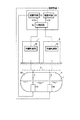
図1に示すように、給油所の地上には、第1および第2計量ユニット1、2が設置されていると共に、事務所内などに制御手段3が設けられている。給油所の地下には、地下タンク(貯油手段)4、供給管5が埋設されている。前記地下タンク4内の1つの閉空間4aには、第1および第2油中ポンプP1、P2が設けられている。これら2台の油中ポンプP1、P2は、それぞれ、前記タンク4に貯溜されている燃料油Lに浸漬されており、前記供給管5を介して、各計量ユニット1、2に燃料油Lを圧送して供給する。
【0013】
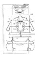
前記供給管5は、各計量ユニット1、2に分岐して配管されており、図2に示すように、各計量ユニット1、2内において、第1および第2ノズルN1、N2に更に分岐している。これらのノズルN1、N2に分岐している供給管5には、各計量ユニット1、2内において、電磁弁11および流量計F/Mが介挿されている。各ノズルN1、N2から吐出される燃料油Lの給油量は、流量計F/Mに接続した流量発信器12によって検出され、計量制御部13を介して、前記ノズルN1、N2の各々に対応する表示器14に表示される。
【0014】
計量ユニット:
前記各計量ユニット1、2は互いに同一の構造、機能を有しており、これらの各計量ユニット1、2には、図2に示すように、前記各ノズル(給油ノズル)N1、N2の数に対応してノズルスイッチ151 ,152 が設けられている。
前記ノズルスイッチ151 ,152 は、各ノズルN1、N2が各計量ユニット1、2のハンガ(図示せず)に掛けられているか否か(ノズルが使用されているか否か)を検出するものである。各ノズルN1、N2がハンガから外されると、各々のノズルに対応するノズルスイッチ151 ,152 から、それぞれ、第1および第2トリガ(給油要求を示す給油信号)T1 、T2 を計量制御部13に出力する。各計量制御部13は、各々、前記第1および第2トリガT1 、T2 に基づいて第1および第2駆動信号a、bを前記制御手段3に出力すると共に、前記電磁弁11および表示器14などを制御する。
【0015】
制御手段:
前記制御手段3は、切換回路(切換手段)32および各油中ポンプP1、P2の駆動手段35を備えている。制御手段3は、切換回路32によって切り換えられる後述の通常モードと非常モードとを有しており、該通常モードまたは非常モードに従って前記油中ポンプの運転を制御するものである。
【0016】
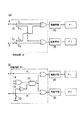
前記切換回路32は、前記計量制御部13と前記各駆動手段35との間に介挿されており、図3(a)に示す第1および第2切換スイッチ(操作部)33、34を備えている。前記第1および第2切換スイッチ33、34は、各々、切換回路32における前記各駆動信号a、bの送信経路を変更して稼働させる油中ポンプを変更するためのものである。つまり、前記各切換スイッチ33、34は、前記各油中ポンプP1、P2の駆動手段35への送信経路上に、それぞれ、設けられた第1および第2接点S1 、S2 のいずれか一方を閉じるように設けられており、閉じる接点を選択的に切り換えることで、各駆動信号a、bの送信経路を変更することができる。
【0017】
図3(a)に示すように、前記第1切換スイッチ33が第1接点S1 を閉じ、前記第2切換スイッチ34が第2接点S2 を閉じている通常モードの場合は、前記計量制御部13からの第1駆動信号aは、第1油中ポンプP1の駆動手段35に出力される。同様に、前記計量制御部13からの第2駆動信号bは、第2油中ポンプP2の駆動手段35に出力される。つまり、第1駆動信号aにより第1油中ポンプP1のみが運転され、第2駆動信号bにより第2油中ポンプP2のみが運転される。したがって、前記第1ノズルN1には、第1油中ポンプP1から給油が行われ、前記第2ノズルN2には、第2油中ポンプP2から給油が行われるように予め設定されている。
【0018】
前記油中ポンプP1、P2のいずれか一方が故障した場合には、当該故障した油中ポンプの駆動手段35への送信経路上に設けられた接点を閉じている切換スイッチを、正常に作動する油中ポンプの駆動手段35への送信経路上に設けられた接点を閉じるように切り換えて非常モードに設定する。たとえば、第1油中ポンプP1が故障した場合には、前記第1切換スイッチ33を操作して第2接点S2 を閉じることで、第1駆動信号aが第2油中ポンプP2の駆動手段35に出力されて第2油中ポンプP2が運転される。一方、第2油中ポンプP2が故障した場合には、前記第2切換スイッチ34を操作して第1接点S1 を閉じることで、第2駆動信号bが第1油中ポンプP1に出力されて第1油中ポンプP1が運転される。
【0019】
以下、前記各モードにおける本給油システムの動作について説明する。
通常モード:
通常モードにおいて、第1計量ユニット1の第1ノズルN1(図2)をハンガから取ると、ノズルスイッチ151 が作動して、対応する表示器14の表示がゼロリセットされる。同時に、第1トリガT1 が計量制御部13に出力され、計量制御部13は第1駆動信号aを制御手段3に出力する。前記制御手段3は、前記第1駆動信号aを前記切換回路32を介して前記第1油中ポンプP1の駆動手段35に出力する。これにより、第1油中ポンプP1は運転を開始し、一方、計量制御部13からの信号で電磁弁111 が開き、第1ノズルN1から燃料油Lが車両に給油される。したがって、通常モードにおいて、1つのノズルを使用する場合には1つの油中ポンプのみが作動し、他の油中ポンプは作動することがないから、電力の浪費を防止し得る。
【0020】
この第1ノズルN1が給油(使用)状態である場合に、第2ノズルN2をハンガから取ると、前記計量制御部13から第2駆動信号bが前記制御手段3に出力され、前記制御手段3は、前記第2駆動信号bを前記切換回路32を介して前記第2油中ポンプP2の駆動手段35に出力する。これにより、第1油中ポンプP1に加え、第2油中ポンプP2が更に運転を開始し、第2ノズルN2から燃料油Lが車両に給油される。したがって、結果的に2台の油中ポンプP1、P2が運転されている状態になる。
【0021】
非常モード:
前記通常モードにおいて、たとえば、第1油中ポンプP1が故障した場合、第1ノズルN1から給油を行うことができなくなる(ただし、例外として、第2ノズルN2が使用されている間だけは、第1ノズルN1から給油を行うことができる。)。かかる場合には、オペレータが前記第1切換スイッチ33を第2接点S2 を閉じるように切換操作することで、非常モードに切り換える。この非常モードにおいては、前記計量制御部13から第1駆動信号aが出力されると、前記切換回路32を介して前記第2油中ポンプP2の駆動手段35に第1駆動信号aが出力される。そのため、前記第2油中ポンプP2に電力が供給され第2油中ポンプP2が運転される。これにより、第2油中ポンプP2から第1ノズルN1に給油可能となる。なお、第2油中ポンプP2が故障した場合には、第2切換スイッチ34を第1接点S1 を閉じるように切換操作することで、第1油中ポンプP1から第2ノズルN2に給油を行うことができる。
【0022】
このように、非常モードにおいては、前記第1および第2油中ポンプP1、P2のいずれか一方が故障しても、正常に作動する他方の油中ポンプから給油を行うことができる。なお、故障した油中ポンプには電力が供給されないようになるので、故障した油中ポンプへの通電による無用のトラブルが発生するおそれがない。
【0023】
ところで、前記切換回路32は、図3(b)に示すように、1つの切換スイッチ33Aを操作して非常モードに切り換えることで、前記第1および第2油中ポンプP1、P2の双方の駆動手段35に駆動信号を出力するような構成としてもよい。すなわち、前記切換スイッチ33Aを開いた通常モードの場合は、前記計量制御部13からの第1駆動信号aは、第1油中ポンプP1の駆動手段35およびAND回路37の双方に出力される。同様に、前記計量制御部13からの第2駆動信号bは、第2油中ポンプP2の駆動手段35およびAND回路37の双方に出力される。
【0024】
この際、前記AND回路37からの出力はなく、前記第1駆動信号aは前記第1油中ポンプP1の駆動手段35だけに出力され、一方、前記第2駆動信号bは前記第2油中ポンプP2の駆動手段35だけに出力される。つまり、第1駆動信号aにより第1油中ポンプP1のみが運転され、第2駆動信号bにより第2油中ポンプP2のみが運転される。
【0025】
一方、前記切換スイッチ33Aを閉じた非常モードの場合は、前記AND回路37から合成駆動信号cが前記第1および第2油中ポンプP1、P2の双方の駆動手段35に出力される。つまり、前記第1および第2駆動信号a、bのいずれか一方が前記切換回路32に出力されると、前記第1および第2ポンプP1、P2の双方に電力が供給される。故障した油中ポンプは電力が供給されても作動することができず、したがって、正常に作動する油中ポンプのみが運転される。
【0026】
ところで、前記制御手段3は、使用しているノズルの数に応じて稼働させる油中ポンプの台数を適宜設定するようにしてもよい。すなわち、前記通常モードにおいて、前記ノズルN1、N2のうち、使用しているノズルの数が2個以下の場合は、一方の油中ポンプP1のみを稼働させて給油を行う。他方、使用しているノズルの数が3個以上になった場合は、もう1台の油中ポンプP2を更に稼働させて、第1および第2油中ポンプP1、P2の2台の油中ポンプで給油を行うように制御してもよい。その場合、下記に説明するように運用してもよい。
【0027】
図4は、第2実施形態における油中ポンプの制御について示す図表である。
この第2実施形態では、前記通常モードにおいて、前記第1および第2油中ポンプP1、P2の各々の稼働量(たとえば、ポンプ稼働時間の積算値)に基づき、給油を行う油中ポンプの設定を前記制御手段3が変更するように制御する。かかる制御において、前記制御手段3は、前記第1および第2油中ポンプP1、P2の各々の稼働量を監視し、かつ、一時的に記憶している。
【0028】
本第2実施形態の通常モードの運用の一例について説明する。
今、基準時間T0 において前記各油中ポンプP1、P2の稼働量の値がゼロリセットされているとする。前記基準時間T0 から所定の時間が経過したT1 において、第2油中ポンプP2の稼働量の値よりも第1油中ポンプP1の稼働量の値が大きい場合は、第1ポンプP1よりも優先的に第2油中ポンプP2を稼働させるように変更設定する。さらに、T1 から所定の時間が経過したT2 において、第1油中ポンプP1の稼働量の値よりも第2油中ポンプP2の稼働量の値が大きくなった場合は、第2ポンプP2よりも優先的に第1油中ポンプP1を稼働させるように再び変更設定する。その後、所定の時間が経過してT3 になると、再び前記各油中ポンプP1、P2の稼働量の値をゼロリセットして、上記と同様の制御を繰り返し行う。このように稼働量の値に基づいて第1および第2油中ポンプP1、P2を概ね交互に稼働させるように制御すれば、第1油中ポンプP1と第2油中ポンプP2との稼働量の差を可及的に小さくすることができる。
なお、稼働量に代えて、各ポンプからの給油量、給油時間またはこれらに対応する値に基づいて制御を行ってもよい。
【0029】
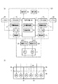
ところで、上記実施形態においては、1つの制御手段3が全ての計量ユニット1、2に対して油中ポンプの制御を行うように構成されていたが、図5(a)に示す第3実施形態のように、各計量ユニット1、2ごとに、前記計量制御部13および切換手段32などの機能を有する制御手段3Aを設けてもよい。
【0030】
また、上記実施形態では、1つの地下タンク4が1つの閉空間に燃料油を貯溜する場合について説明したが、図5(b)に示すように、隔壁41によって内部が区画された地下タンク4Aの閉空間4aごとに複数台の油中ポンプを設けてもよい。
【0031】
以上のとおり、図面を参照しながら好適な実施形態を説明したが、当業者であれば、本明細書を見て、自明な範囲で種々の変更および修正を容易に想定するであろう。
たとえば、上記実施形態では、説明を分かり易くするために計量ユニット1、2が2台である場合について説明したが、本発明は、計量ユニットが3台以上である場合についても適用できる。また、油中ポンプについても1つの閉空間に対し3台以上設けてもよい。
また、切換手段は必ずしも切換回路(アナログ回路)32で構成する必要はなく、同様の動作を制御手段に行わせるプログラムを記憶したメモリなどで前記切換手段を構成してもよい。
したがって、そのような変更および修正は、請求の範囲から定まる本発明の範囲内のものと解釈される。
【0032】
【発明の効果】
以上説明したように本発明によれば、燃料油を貯溜する1つの閉空間に対して複数台の油中ポンプを設けたので、貯油手段を大型化することができる。しかも、通常モードにおいて常に全ての油中ポンプを運転させるのではなく、必要なポンプのみを必要な台数だけ運転させるので、必要以上の吐出圧になったり、あるいは、電力の浪費を防止し得る。
さらに、1台の油中ポンプが故障しても他の油中ポンプにより給油を行うことができるから、貯油手段内の燃料油を最後まで使い切ることができる
また、貯油手段を大型化することができるから、油種ごとの貯油手段の数を減らすことができるので、燃料油を補充する際に油種を間違えて補充する可能性が低下する。しかも、補充車からの荷卸しの際、複雑な制御を必要とせず、また、貯油手段との接続回数も減るから燃料油補充の効率が向上する。
【0033】
また、オペレータが切換手段の操作部を操作することにより、通常モードと非常モードとを手動で切り換えるようにすれば、モードの切り換え時に予期しないタイミングで、ノズルから燃料油が吐出されるおそれがない。
【0034】
また、ノズルスイッチが作動すると、当該ノズルスイッチに対応する油中ポンプが稼働するように予め設定しておけば、油中ポンプの運転制御が簡便になる。
【0035】
また、各油中ポンプからの給油量、給油時間または油中ポンプの稼働量、あるいは、これらに対応する値に基づいて前記油中ポンプの設定を前記制御手段が行うようにすれば、各油中ポンプの稼働量が均等になり、油中ポンプの耐久性が向上する。
【0036】
また、使用しているノズルの数に応じて、運転する油中ポンプの台数を設定するようにすれば、無駄な電力の消費がなく効率的に本給油システムを運用することができる。
【0037】
また、前記切換手段により1つの制御手段のモードを切り換えることにより、全ての計量ユニットに対して各油中ポンプの運転制御を変更可能とすれば、一度の操作により全ての計量ユニットのモードの切り換えを容易に行うことができる。
【図面の簡単な説明】
【図1】本発明の第1実施形態を示す概略構成図である。
【図2】計量ユニット等を示す概略構成図である。
【図3】切換回路の一例を示す概略構成図である。
【図4】第2実施形態にかかる制御方法を示すタイムチャートである。
【図5】(a)は計量ユニットの変形例を示す概略構成図、(b)は貯油手段の変形例を示す概略側面図である。
【符号の説明】
1、2:計量ユニット
3:制御手段
32:切換回路(切換手段)
33、34:切換スイッチ(操作部)
4:地下タンク(貯油手段)
4a:閉空間
5:供給管
13:計量制御部
15:ノズルスイッチ
N1、N2:ノズル
L:燃料油
P1、P2:油中ポンプ[0001]
TECHNICAL FIELD OF THE INVENTION
The present invention relates to an oil supply system for pumping fuel oil from a submerged pump immersed in fuel oil to a plurality of measuring units.
[0002]
[Prior art]
In a refueling system using a ground pump that sucks fuel oil from the ground at a negative pressure, the fuel oil is gasified by the negative pressure due to the suction, and thus cannot cope with the recent tendency for underground tanks to become larger. On the other hand, in a refueling system using an in-oil pump, no negative pressure is generated in the fuel oil. Therefore, by increasing the discharge pressure, the fuel oil can be supplied from a large underground tank.
[0003]
In such an oil pump refueling system, there is known an oil refueling system in which one oil pump is immersed in an underground tank and fuel oil is distributed to a plurality of measuring units (for example, see Patent Document 1).
[0004]
[Patent Document 1]
JP-A-10-24999 (page 2-3, FIG. 1)
[0005]
[Problems to be solved by the invention]
However, in the invention of
[0006]
Therefore, an object of the present invention is to solve the above-mentioned problems, to provide an underground tank that can be enlarged, and to provide a refueling system capable of refueling even if a submerged pump fails without providing a spare pump. It is to be.
[0007]
[Means for Solving the Problems]
In order to achieve the above object, an oil supply system according to the present invention includes a plurality of measuring units that measure fuel oil discharged from a nozzle and display the measured fuel oil on a display, and an oil storage that stores the fuel oil in one closed space. Means, a plurality of in-oil pumps provided for the one closed space, a supply pipe for supplying fuel oil pumped by the in-oil pump to each of the nozzles, and the plurality of in-oil pumps One or more of the submersible pumps are set, the normal mode in which refueling is performed from the set submersible pump, and normal operation when one of the submersible pumps is out of order. It has an emergency mode in which oil is supplied from another oil pump, and includes control means for controlling the operation of the oil pump, and switching means for switching between the normal mode and the emergency mode.
[0008]
In the refueling system of the present invention, a plurality of in-oil pumps that are constantly used are provided in one closed space in which fuel oil is stored, and refueling is performed from the set in-oil pump. If the set submersible oil pump fails and refueling cannot be performed, the emergency mode is changed and set by the switching means so that refueling can be performed from another normally operating submersible pump.
[0009]
In the present invention, a nozzle switch for detecting the use of each nozzle may be provided, and an oil pump for supplying oil to a plurality of nozzles may be set in advance. That is, when the nozzle switch is operated, the control unit controls the preset oil pump to operate, so that the oil pump control is simplified.
[0010]
In the present invention, the control means may appropriately set the number of in-oil pumps to be operated according to the number of nozzles used. That is, when the number of used nozzles is equal to or less than a predetermined number m, oil is supplied by a predetermined one oil pump, and the number of used nozzles exceeds the m and is (m + 1). In the case described above, control may be performed such that refueling is performed by two or more in-oil pumps.
[0011]
DETAILED DESCRIPTION OF THE INVENTION
Hereinafter, embodiments of the present invention will be described with reference to the drawings.
1 to 3 show a first embodiment.
In the following description, for convenience of explanation, a refueling system for supplying only a single oil type (for example, regular gasoline) will be described, but a plurality of oils including other oil types (for example, high-octane gasoline, light oil, etc.) will be described. The invention can be applied to a refueling system for refueling seeds.
[0012]
overall structure:
As shown in FIG. 1, first and
[0013]
The
[0014]
Weighing unit:
Each of the
The nozzle switches 15 1 and 15 2 detect whether the
[0015]
Control means:
The control means 3 includes a switching circuit (switching means) 32 and driving means 35 for each of the in-oil pumps P1, P2. The control means 3 has a later-described normal mode and an emergency mode which are switched by the switching circuit 32, and controls the operation of the submersible pump according to the normal mode or the emergency mode.
[0016]
The switching circuit 32 is interposed between the weighing
[0017]
As shown in FIG. 3 (a), the
[0018]
When one of the oil pumps P1 and P2 fails, the changeover switch that closes the contact provided on the transmission path to the drive means 35 of the failed oil pump is operated normally. The emergency mode is set by switching so as to close a contact provided on a transmission path to the
[0019]
Hereinafter, the operation of the present refueling system in each mode will be described.
Normal mode:
In normal mode, taking first the first nozzle N1 of the measuring unit 1 (FIG. 2) from the hanger, the
[0020]
If the second nozzle N2 is taken out of the hanger when the first nozzle N1 is in a refueling (use) state, a second drive signal b is output from the
[0021]
Emergency mode:
In the normal mode, for example, when the first oil pump P1 fails, oil cannot be supplied from the first nozzle N1 (except as long as the second nozzle N2 is used, Refueling can be performed from one nozzle N1.) In such a case, that the operator switch operates the
[0022]
Thus, in the emergency mode, even if one of the first and second oil pumps P1 and P2 fails, oil can be supplied from the other normally operating oil pump. Since no power is supplied to the failed oil pump, there is no possibility that an unnecessary trouble will occur due to the supply of electricity to the failed oil pump.
[0023]
By the way, as shown in FIG. 3B, the switching circuit 32 operates one switching switch 33A to switch to the emergency mode, thereby driving both the first and second oil pumps P1 and P2. A configuration may be such that a drive signal is output to the
[0024]
At this time, there is no output from the AND circuit 37, and the first drive signal a is output only to the drive means 35 of the first oil pump P1, while the second drive signal b is output from the second oil pump P1. It is output only to the driving means 35 of the pump P2. That is, only the first oil pump P1 is operated by the first drive signal a, and only the second oil pump P2 is operated by the second drive signal b.
[0025]
On the other hand, in the emergency mode in which the changeover switch 33A is closed, the combined drive signal c is output from the AND circuit 37 to the drive means 35 of both the first and second in-oil pumps P1 and P2. That is, when one of the first and second drive signals a and b is output to the switching circuit 32, power is supplied to both the first and second pumps P1 and P2. The failed oil pump cannot operate even when the power is supplied, and therefore, only the normally operating oil pump is operated.
[0026]
Incidentally, the control means 3 may appropriately set the number of in-oil pumps to be operated according to the number of nozzles used. That is, in the normal mode, when the number of nozzles used among the nozzles N1 and N2 is two or less, only one of the in-oil pumps P1 is operated to supply oil. On the other hand, when the number of used nozzles becomes three or more, the other oil pump P2 is further operated, and the two oil pumps P1 and P2 are operated. Control may be performed so that refueling is performed by a pump. In that case, the operation may be performed as described below.
[0027]
FIG. 4 is a chart showing control of the submersible pump in the second embodiment.
In the second embodiment, in the normal mode, the setting of the in-oil pump for refueling is performed based on the operating amounts of the first and second in-oil pumps P1 and P2 (for example, the integrated value of the pump operating time). Is controlled by the control means 3. In this control, the control means 3 monitors the operation amounts of the first and second sub-oil pumps P1 and P2 and temporarily stores the operation amounts.
[0028]
An example of the operation in the normal mode according to the second embodiment will be described.
Now, with the value of the operating amount of the oil pumps P1, P2 is the reference time T 0 is reset to zero. In T 1 of the reference time T 0 from the predetermined time has elapsed, if than operating amount of the value of the second oil pump P2 is the value of the operating amount of the first oil pump P1 larger than the first pump P1 Is also changed and set to operate the second oil pump P2 preferentially. Further, the T 2 has elapsed a predetermined time from T 1, if than operating amount of the value of the first oil pump P1 is the value of the operating amount of the second oil pump P2 becomes large, the second pump P2 The setting is changed again so that the first oil pump P1 is operated with higher priority than the above. Thereafter, when the T 3 has passed a predetermined time, the value of the operating amount of the oil pumps P1, P2 and zero reset again to repeat the same control as described above. In this way, if the first and second oil pumps P1 and P2 are controlled to operate substantially alternately based on the value of the operation amount, the operation amount of the first oil pump P1 and the second oil pump P2 is controlled. Can be made as small as possible.
Control may be performed based on the amount of oil supplied from each pump, the time of oil supply, or a value corresponding to these, instead of the operation amount.
[0029]
By the way, in the above embodiment, one control means 3 is configured to control the in-oil pump for all the
[0030]
In the above embodiment, the case where one
[0031]
As described above, the preferred embodiments have been described with reference to the drawings. However, those skilled in the art will easily envisage various changes and modifications within the obvious scope upon reading this specification.
For example, in the above embodiment, the case where the number of the weighing
Further, the switching means does not necessarily need to be constituted by the switching circuit (analog circuit) 32, and the switching means may be constituted by a memory storing a program for causing the control means to perform the same operation.
Accordingly, such changes and modifications are to be construed as being within the scope of the invention as defined by the appended claims.
[0032]
【The invention's effect】
As described above, according to the present invention, since a plurality of in-oil pumps are provided for one closed space for storing fuel oil, the size of the oil storage means can be increased. In addition, in the normal mode, not all the submersible pumps are always operated, but only the necessary pumps are operated by the required number. Therefore, it is possible to prevent the discharge pressure from becoming higher than necessary or to waste power.
Furthermore, even if one of the oil pumps fails, refueling can be performed by another oil pump, so that the fuel oil in the oil storage means can be completely used up, and the oil storage means can be enlarged. Since it is possible, the number of oil storage means for each oil type can be reduced, and the possibility of erroneously refilling the oil type when replenishing fuel oil is reduced. Moreover, when unloading from the replenishing vehicle, complicated control is not required, and the number of times of connection with the oil storage means is reduced, so that the efficiency of fuel oil replenishment is improved.
[0033]
Further, if the operator manually switches between the normal mode and the emergency mode by operating the operation unit of the switching unit, there is no possibility that fuel oil is discharged from the nozzle at unexpected timing when the mode is switched. .
[0034]
In addition, when the nozzle switch is set in advance so that the oil pump corresponding to the nozzle switch is operated, the operation control of the oil pump is simplified.
[0035]
In addition, if the control unit sets the oil pump based on the amount of oil supplied from each oil pump, the oil supply time, the operating amount of the oil pump, or a value corresponding to each, each oil is The operation amount of the middle pump is equalized, and the durability of the middle pump is improved.
[0036]
Further, if the number of operating oil pumps is set according to the number of nozzles used, the fuel supply system can be operated efficiently without wasteful power consumption.
[0037]
Further, if the operation control of each submersible pump can be changed for all the measuring units by switching the mode of one control means by the switching means, the mode of all the measuring units can be switched by one operation. Can be easily performed.
[Brief description of the drawings]
FIG. 1 is a schematic configuration diagram showing a first embodiment of the present invention.
FIG. 2 is a schematic configuration diagram showing a weighing unit and the like.
FIG. 3 is a schematic configuration diagram illustrating an example of a switching circuit.
FIG. 4 is a time chart illustrating a control method according to a second embodiment.
5A is a schematic configuration diagram showing a modified example of the measuring unit, and FIG. 5B is a schematic side view showing a modified example of the oil storage means.
[Explanation of symbols]
1, 2: weighing unit 3: control means 32: switching circuit (switching means)
33, 34: changeover switch (operation unit)
4: Underground tank (oil storage means)
4a: Closed space 5: Supply pipe 13: Metering control unit 15: Nozzle switch N1, N2: Nozzle L: Fuel oil P1, P2: Pump in oil
Claims (6)
前記燃料油を1つの閉空間に貯溜する貯油手段と、
前記1つの閉空間に対して設けられた複数台の油中ポンプと、
前記油中ポンプによって圧送される燃料油を前記各ノズルに供給する供給管と、
前記複数台の油中ポンプのうち1台または複数台の油中ポンプが設定され、当該設定された油中ポンプから給油を行う通常モードと、前記油中ポンプのうち1台が故障している場合に、正常に作動する別の油中ポンプから給油を行う非常モードとを有し、前記油中ポンプの運転を制御する制御手段と、
前記通常モードと非常モードとを切り換える切換手段とを備えている給油システム。A plurality of measuring units for measuring fuel oil discharged from the nozzle,
Oil storage means for storing the fuel oil in one closed space;
A plurality of oil pumps provided for the one closed space;
A supply pipe for supplying the fuel oil pumped by the oil pump to each of the nozzles,
One or more of the plurality of in-oil pumps are set, and a normal mode in which refueling is performed from the set in-oil pump, and one of the in-oil pumps has failed. In the case, an emergency mode for refueling from another oil pump that operates normally, and control means for controlling the operation of the oil pump,
A refueling system comprising a switching means for switching between the normal mode and the emergency mode.
前記切換手段は操作部を備え、オペレータが前記操作部を操作することにより、前記通常モードと前記非常モードとを切り換え可能にした給油システム。In claim 1,
The fuel supply system, wherein the switching means includes an operation unit, and an operator operates the operation unit to switch between the normal mode and the emergency mode.
前記ノズルには、ノズルの使用を検知するノズルスイッチが設けられ、
前記複数のノズルに対して、それぞれ、通常モードにおいて給油を行う油中ポンプが予め設定されており、前記通常モードにおいて前記ノズルのノズルスイッチが作動すると、当該ノズルスイッチに対応する前記予め設定された油中ポンプが稼働して給油を行う給油システム。In claim 1 or 2,
The nozzle is provided with a nozzle switch for detecting use of the nozzle,
For each of the plurality of nozzles, an in-oil pump that supplies oil in the normal mode is set in advance, and when the nozzle switch of the nozzle is operated in the normal mode, the preset oil pressure corresponding to the nozzle switch is set. A refueling system in which an in-oil pump operates to refuel.
各油中ポンプからの給油量、給油時間または油中ポンプの稼働量、あるいは、これらに対応する値に基づいて、前記通常モードにおける前記油中ポンプの設定を前記制御手段が行う給油システム。In claim 1 or 2,
An oil supply system in which the control unit performs setting of the oil pump in the normal mode based on an amount of oil supplied from each oil pump, an oil supply time, an operation amount of the oil pump, or a value corresponding thereto.
前記制御手段は、使用しているノズルの数が所定のm個以下の場合は、所定の1台の油中ポンプによって給油を行い、使用しているノズルの数が前記m個を越えて(m+1)個以上になった場合は、2台以上の油中ポンプによって給油を行う給油システム。In any one of claims 1, 2 or 4,
When the number of nozzles used is equal to or less than a predetermined number m, the control means performs refueling by a predetermined one oil-in-oil pump, and the number of nozzles used exceeds the number m. An oil supply system in which two or more oil pumps are used to supply oil when m + 1) or more oil tanks are used.
前記計量ユニットは、各々、計量を制御する計量制御部を備え、
前記制御手段は、前記各計量制御部からの信号に基づいて各油中ポンプの運転を制御し、
前記切換手段により前記制御手段のモードを切り換えることにより、全ての計量ユニットに対して各油中ポンプの運転制御を変更可能な給油システム。In any one of claims 1 to 5,
The weighing units each include a weighing control unit that controls weighing,
The control means controls the operation of each in-oil pump based on a signal from each of the measurement control units,
An oil supply system capable of changing the operation control of each submerged pump for all the measuring units by switching the mode of the control means by the switching means.
Priority Applications (1)
| Application Number | Priority Date | Filing Date | Title |
|---|---|---|---|
| JP2002367597A JP3682775B2 (en) | 2002-12-19 | 2002-12-19 | Lubrication system |
Applications Claiming Priority (1)
| Application Number | Priority Date | Filing Date | Title |
|---|---|---|---|
| JP2002367597A JP3682775B2 (en) | 2002-12-19 | 2002-12-19 | Lubrication system |
Publications (2)
| Publication Number | Publication Date |
|---|---|
| JP2004196366A true JP2004196366A (en) | 2004-07-15 |
| JP3682775B2 JP3682775B2 (en) | 2005-08-10 |
Family
ID=32764441
Family Applications (1)
| Application Number | Title | Priority Date | Filing Date |
|---|---|---|---|
| JP2002367597A Expired - Fee Related JP3682775B2 (en) | 2002-12-19 | 2002-12-19 | Lubrication system |
Country Status (1)
| Country | Link |
|---|---|
| JP (1) | JP3682775B2 (en) |
Cited By (1)
| Publication number | Priority date | Publication date | Assignee | Title |
|---|---|---|---|---|
| CN106744613A (en) * | 2016-12-24 | 2017-05-31 | 浙江朗庆智能科技有限公司 | Full-service fluid loading system |
-
2002
- 2002-12-19 JP JP2002367597A patent/JP3682775B2/en not_active Expired - Fee Related
Cited By (1)
| Publication number | Priority date | Publication date | Assignee | Title |
|---|---|---|---|---|
| CN106744613A (en) * | 2016-12-24 | 2017-05-31 | 浙江朗庆智能科技有限公司 | Full-service fluid loading system |
Also Published As
| Publication number | Publication date |
|---|---|
| JP3682775B2 (en) | 2005-08-10 |
Similar Documents
| Publication | Publication Date | Title |
|---|---|---|
| US6625519B2 (en) | Pump controller for submersible turbine pumps | |
| US20070051423A1 (en) | Pressure Differential System for Controlling High Pressure Refill Gas Flow Into On Board Vehicle Fuel Tanks | |
| CN100582471C (en) | Fuel supply device for a motor vehicle | |
| JP2009528162A (en) | Liquid dispensing system | |
| US20110297260A1 (en) | Fuel system including dual fuel delivery modules for bifurcated fuel tanks | |
| CN114290895B (en) | Oil supply system and control method thereof | |
| JP7013155B2 (en) | Liquid fuel supply device | |
| JP2016156288A (en) | Fuel tank system | |
| CN215566328U (en) | Vehicle fuel supply structure and vehicle | |
| EP2751398B1 (en) | Oil management system for an internal combustion engine, and a method for oil management of such an engine | |
| JP2004196366A (en) | Fueling system | |
| RU2005107586A (en) | FILLING DEVICE | |
| JP2000220429A (en) | Automatic oil supplying device for stationary engine | |
| KR100875700B1 (en) | Fuel filter clogging detection system and detection method of fuel supply device for gas vehicle | |
| JP3076198B2 (en) | Gas generator | |
| JP4027791B2 (en) | Lubrication system | |
| JP2007182242A (en) | Liquid supply system | |
| JP2010043777A (en) | Liquid fuel combustion apparatus | |
| JP5030395B2 (en) | Control method of pump | |
| US20080017249A1 (en) | Slurry dispensing system | |
| US20240262316A1 (en) | Cleaning liquid reservoir system, sensor cleaning system, vehicle | |
| JP2004238825A (en) | Water supply system in water works | |
| KR102856990B1 (en) | Foam tank system to maintain foam level and prevent overflow | |
| JP3500859B2 (en) | Refueling device | |
| RU2323857C1 (en) | Plane fuel system |
Legal Events
| Date | Code | Title | Description |
|---|---|---|---|
| A621 | Written request for application examination |
Free format text: JAPANESE INTERMEDIATE CODE: A621 Effective date: 20040602 |
|
| A871 | Explanation of circumstances concerning accelerated examination |
Free format text: JAPANESE INTERMEDIATE CODE: A871 Effective date: 20041012 |
|
| A975 | Report on accelerated examination |
Free format text: JAPANESE INTERMEDIATE CODE: A971005 Effective date: 20041125 |
|
| A131 | Notification of reasons for refusal |
Free format text: JAPANESE INTERMEDIATE CODE: A131 Effective date: 20041207 |
|
| A521 | Written amendment |
Free format text: JAPANESE INTERMEDIATE CODE: A523 Effective date: 20050124 |
|
| TRDD | Decision of grant or rejection written | ||
| A01 | Written decision to grant a patent or to grant a registration (utility model) |
Free format text: JAPANESE INTERMEDIATE CODE: A01 Effective date: 20050517 |
|
| A61 | First payment of annual fees (during grant procedure) |
Free format text: JAPANESE INTERMEDIATE CODE: A61 Effective date: 20050518 |
|
| R150 | Certificate of patent or registration of utility model |
Ref document number: 3682775 Country of ref document: JP Free format text: JAPANESE INTERMEDIATE CODE: R150 Free format text: JAPANESE INTERMEDIATE CODE: R150 |
|
| FPAY | Renewal fee payment (event date is renewal date of database) |
Free format text: PAYMENT UNTIL: 20080603 Year of fee payment: 3 |
|
| FPAY | Renewal fee payment (event date is renewal date of database) |
Free format text: PAYMENT UNTIL: 20090603 Year of fee payment: 4 |
|
| FPAY | Renewal fee payment (event date is renewal date of database) |
Free format text: PAYMENT UNTIL: 20100603 Year of fee payment: 5 |
|
| FPAY | Renewal fee payment (event date is renewal date of database) |
Free format text: PAYMENT UNTIL: 20110603 Year of fee payment: 6 |
|
| FPAY | Renewal fee payment (event date is renewal date of database) |
Free format text: PAYMENT UNTIL: 20120603 Year of fee payment: 7 |
|
| FPAY | Renewal fee payment (event date is renewal date of database) |
Free format text: PAYMENT UNTIL: 20130603 Year of fee payment: 8 |
|
| FPAY | Renewal fee payment (event date is renewal date of database) |
Free format text: PAYMENT UNTIL: 20140603 Year of fee payment: 9 |
|
| LAPS | Cancellation because of no payment of annual fees |