JP2004196651A - Method and apparatus for manufacturing glass substrate for storage medium, glass substrate for storage medium, and storage medium - Google Patents
Method and apparatus for manufacturing glass substrate for storage medium, glass substrate for storage medium, and storage medium Download PDFInfo
- Publication number
- JP2004196651A JP2004196651A JP2003394581A JP2003394581A JP2004196651A JP 2004196651 A JP2004196651 A JP 2004196651A JP 2003394581 A JP2003394581 A JP 2003394581A JP 2003394581 A JP2003394581 A JP 2003394581A JP 2004196651 A JP2004196651 A JP 2004196651A
- Authority
- JP
- Japan
- Prior art keywords
- mold
- storage medium
- glass substrate
- glass material
- cooling
- Prior art date
- Legal status (The legal status is an assumption and is not a legal conclusion. Google has not performed a legal analysis and makes no representation as to the accuracy of the status listed.)
- Withdrawn
Links
Images


Classifications
-
- C—CHEMISTRY; METALLURGY
- C03—GLASS; MINERAL OR SLAG WOOL
- C03B—MANUFACTURE, SHAPING, OR SUPPLEMENTARY PROCESSES
- C03B11/00—Pressing molten glass or performed glass reheated to equivalent low viscosity without blowing
- C03B11/12—Cooling, heating, or insulating the plunger, the mould, or the glass-pressing machine; cooling or heating of the glass in the mould
- C03B11/122—Heating
-
- C—CHEMISTRY; METALLURGY
- C03—GLASS; MINERAL OR SLAG WOOL
- C03B—MANUFACTURE, SHAPING, OR SUPPLEMENTARY PROCESSES
- C03B11/00—Pressing molten glass or performed glass reheated to equivalent low viscosity without blowing
- C03B11/005—Pressing under special atmospheres, e.g. inert, reactive, vacuum, clean
-
- C—CHEMISTRY; METALLURGY
- C03—GLASS; MINERAL OR SLAG WOOL
- C03B—MANUFACTURE, SHAPING, OR SUPPLEMENTARY PROCESSES
- C03B11/00—Pressing molten glass or performed glass reheated to equivalent low viscosity without blowing
- C03B11/06—Construction of plunger or mould
- C03B11/08—Construction of plunger or mould for making solid articles, e.g. lenses
- C03B11/088—Flat discs
-
- C—CHEMISTRY; METALLURGY
- C03—GLASS; MINERAL OR SLAG WOOL
- C03B—MANUFACTURE, SHAPING, OR SUPPLEMENTARY PROCESSES
- C03B11/00—Pressing molten glass or performed glass reheated to equivalent low viscosity without blowing
- C03B11/12—Cooling, heating, or insulating the plunger, the mould, or the glass-pressing machine; cooling or heating of the glass in the mould
- C03B11/125—Cooling
-
- C—CHEMISTRY; METALLURGY
- C03—GLASS; MINERAL OR SLAG WOOL
- C03B—MANUFACTURE, SHAPING, OR SUPPLEMENTARY PROCESSES
- C03B2215/00—Press-moulding glass
- C03B2215/02—Press-mould materials
- C03B2215/08—Coated press-mould dies
- C03B2215/10—Die base materials
- C03B2215/12—Ceramics or cermets, e.g. cemented WC, Al2O3 or TiC
-
- C—CHEMISTRY; METALLURGY
- C03—GLASS; MINERAL OR SLAG WOOL
- C03B—MANUFACTURE, SHAPING, OR SUPPLEMENTARY PROCESSES
- C03B2215/00—Press-moulding glass
- C03B2215/02—Press-mould materials
- C03B2215/08—Coated press-mould dies
- C03B2215/14—Die top coat materials, e.g. materials for the glass-contacting layers
- C03B2215/16—Metals or alloys, e.g. Ni-P, Ni-B, amorphous metals
-
- C—CHEMISTRY; METALLURGY
- C03—GLASS; MINERAL OR SLAG WOOL
- C03B—MANUFACTURE, SHAPING, OR SUPPLEMENTARY PROCESSES
- C03B2215/00—Press-moulding glass
- C03B2215/02—Press-mould materials
- C03B2215/08—Coated press-mould dies
- C03B2215/14—Die top coat materials, e.g. materials for the glass-contacting layers
- C03B2215/16—Metals or alloys, e.g. Ni-P, Ni-B, amorphous metals
- C03B2215/17—Metals or alloys, e.g. Ni-P, Ni-B, amorphous metals comprising one or more of the noble meals, i.e. Ag, Au, platinum group metals
-
- C—CHEMISTRY; METALLURGY
- C03—GLASS; MINERAL OR SLAG WOOL
- C03B—MANUFACTURE, SHAPING, OR SUPPLEMENTARY PROCESSES
- C03B2215/00—Press-moulding glass
- C03B2215/40—Product characteristics
- C03B2215/44—Flat, parallel-faced disc or plate products
-
- C—CHEMISTRY; METALLURGY
- C03—GLASS; MINERAL OR SLAG WOOL
- C03B—MANUFACTURE, SHAPING, OR SUPPLEMENTARY PROCESSES
- C03B2215/00—Press-moulding glass
- C03B2215/66—Means for providing special atmospheres, e.g. reduced pressure, inert gas, reducing gas, clean room
-
- Y—GENERAL TAGGING OF NEW TECHNOLOGICAL DEVELOPMENTS; GENERAL TAGGING OF CROSS-SECTIONAL TECHNOLOGIES SPANNING OVER SEVERAL SECTIONS OF THE IPC; TECHNICAL SUBJECTS COVERED BY FORMER USPC CROSS-REFERENCE ART COLLECTIONS [XRACs] AND DIGESTS
- Y02—TECHNOLOGIES OR APPLICATIONS FOR MITIGATION OR ADAPTATION AGAINST CLIMATE CHANGE
- Y02P—CLIMATE CHANGE MITIGATION TECHNOLOGIES IN THE PRODUCTION OR PROCESSING OF GOODS
- Y02P40/00—Technologies relating to the processing of minerals
- Y02P40/50—Glass production, e.g. reusing waste heat during processing or shaping
- Y02P40/57—Improving the yield, e-g- reduction of reject rates
Landscapes
- Engineering & Computer Science (AREA)
- Chemical & Material Sciences (AREA)
- Manufacturing & Machinery (AREA)
- Materials Engineering (AREA)
- Organic Chemistry (AREA)
- Manufacturing Of Magnetic Record Carriers (AREA)
Abstract
【課題】 高品質の記憶媒体用基板をプレス成形で好適に作成する。
【解決手段】 ガラス素材8を上金型1aと下金型1bとの間に配置したまま加熱および加圧成形する工程に続き、上金型1aと下金型1bとに水冷ジャケット3a,3bを接触させて冷却する。加熱から加圧成形の間は、金型1a,1bとガラス素材8とを含むチャンバー18内の雰囲気を真空に保ち、加圧成形が終了した際、チャンバー18に不活性ガスを充填して大気圧とし、その後冷却工程を行う。
【選択図】 図1
PROBLEM TO BE SOLVED: To suitably produce a high quality storage medium substrate by press molding.
SOLUTION: Following a step of heating and press-forming while a glass material 8 is arranged between an upper mold 1a and a lower mold 1b, water cooling jackets 3a, 3b are provided on the upper mold 1a and the lower mold 1b. And cooled. During the period from heating to pressure molding, the atmosphere in the chamber 18 including the dies 1a and 1b and the glass material 8 is kept at a vacuum. Atmospheric pressure, followed by a cooling step.
[Selection diagram] Fig. 1
Description
本発明は、磁気ディスクなどの記憶媒体に適したガラス基板の製造方法および装置、これを用いた記憶媒体用ガラス基板および記憶媒体に関する。 The present invention relates to a method and an apparatus for manufacturing a glass substrate suitable for a storage medium such as a magnetic disk, a glass substrate for a storage medium using the same, and a storage medium.
従来、磁気ディスク用ガラス基板は、所定のサイズに切り抜かれた基板を、平滑な表面を得るために研磨する研磨法により製造されてきた。しかしながら、近年、基板には高い平滑性が要求されるようになったため、研磨法は多くの工程を要し、製品の高価格化につながるという欠点があった。 Conventionally, a glass substrate for a magnetic disk has been manufactured by a polishing method of polishing a substrate cut out to a predetermined size in order to obtain a smooth surface. However, in recent years, since high smoothness has been required for the substrate, the polishing method has many drawbacks, and has a drawback that the price of the product is increased.
一方、ガラス素材を加熱、成形、冷却し、金型成形面を高精度で転写するプレス成形方法は、後加工を必要としないため、安価で生産性が高い。したがって、光学素子の製造分野では、プレス成形方法に関して既に多くの検討がなされ実用化が試みられている。 On the other hand, a press molding method in which a glass material is heated, molded, and cooled, and a mold molding surface is transferred with high precision does not require any post-processing, and thus is inexpensive and has high productivity. Therefore, in the field of manufacturing optical elements, many studies have been made on the press molding method, and practical use has been attempted.
光学素子の製造に用いられている従来のプレス成形の工程は、概略次の通りである。上下の型の間にガラス素材をセットし、金型の酸化を防止する目的で、金型とガラス素材を収容する成形室の雰囲気を、窒素ガスなどの不活性ガスで置換する。その後、ヒータ(誘導加熱装置、ランプ加熱装置、カートリッジヒータ等)を用いて金型とガラス素材とを加熱する。所定の温度に到達した後、上下の型を用いてガラス素材をプレスし、最後に冷却して製品を取り出す。 A conventional press molding process used for manufacturing an optical element is roughly as follows. A glass material is set between the upper and lower molds, and the atmosphere in the molding chamber that houses the mold and the glass material is replaced with an inert gas such as nitrogen gas in order to prevent oxidation of the mold. Thereafter, the mold and the glass material are heated using a heater (such as an induction heating device, a lamp heating device, or a cartridge heater). After reaching a predetermined temperature, the glass material is pressed using upper and lower molds, and finally, the product is taken out by cooling.
このような光学素子のプレス成形において、エア溜まりによる欠陥と型の酸化を防止する方策として、減圧された雰囲気中でプレスし、不活性ガスを金型に吹き付けて冷却する方法が提案されている(例えば、特許文献1参照)。 In press molding of such an optical element, as a measure to prevent defects due to air accumulation and oxidation of the mold, a method has been proposed in which the mold is pressed in a reduced-pressure atmosphere and cooled by blowing an inert gas onto the mold. (For example, see Patent Document 1).
他方、磁気ディスク用ガラス基板を製造するために、加熱、プレス、冷却の各工程を、それぞれ個別の室で行う方法も提案されている(例えば、特許文献2参照)。 On the other hand, in order to manufacture a glass substrate for a magnetic disk, a method has been proposed in which each of heating, pressing, and cooling steps is performed in a separate chamber (for example, see Patent Document 2).
しかしながら、プレス成形方法によって、磁気ディスク用ガラス基板を製造することは、光学素子の場合とは違った課題を有している。 However, producing a glass substrate for a magnetic disk by a press molding method has a different problem from that of an optical element.
すなわち、ハードディスク用媒体の基板は、光学素子に比べて大面積かつ、基板厚が薄いにもかかわらず、面のうねりができるだけ小さいこと(平坦度)、特に周方向でのうねりを抑えること、および内外径の寸法精度を上げることが求められている。例えば2.5インチのディスクでは、4μm以下の平坦度が要求されうる。これは、特に高速回転時における磁気ヘッドの追従性を高めるためである。 That is, the substrate of the medium for a hard disk has a large surface area as compared with the optical element and has a surface undulation as small as possible (flatness), particularly suppressing the undulation in the circumferential direction, even though the substrate thickness is small, and It is required to increase the dimensional accuracy of the inner and outer diameters. For example, a 2.5 inch disk may require a flatness of 4 μm or less. This is to improve the followability of the magnetic head particularly during high-speed rotation.
金型にガスを吹き付けて冷却する特許文献1の方法は、均一温度での冷却が難しく、冷却の不均一さに起因する基板の変形が生じるため、基板の好適な平坦さを提供することが難しい。 The method disclosed in Patent Literature 1 in which a gas is blown onto a mold to cool the mold is difficult to cool at a uniform temperature, and deformation of the substrate due to non-uniform cooling occurs, so that it is possible to provide a suitable flatness of the substrate. difficult.
また、特許文献2の方法では、成形工程中にそれぞれの室の間を搬送するときに、チャック跡や歪みが生じるおそれがある。 In addition, in the method of Patent Document 2, there is a possibility that chuck marks or distortion may occur when the sheet is transferred between the respective chambers during the molding process.
本発明は上記のような従来技術の問題点に鑑みて、高品質の記憶媒体用基板をプレス成形で好適に作成するための手段を提供することを目的とする。 The present invention has been made in view of the above-described problems of the related art, and has as its object to provide means for suitably producing a high-quality storage medium substrate by press molding.
上記目的を達成するため、本発明の記憶媒体用ガラス基板の製造方法は、上金型と下金型との間にガラス素材を配置し、ガラス基板をプレス成形する記憶媒体用ガラス基板の製造方法において、前記ガラス素材を前記上金型と下金型との間に配置したまま加熱する加熱工程と、前記加熱された前記ガラス素材を前記上金型と下金型とを介してプレスし、前記上金型と下金型との成形面を精密に転写して所望の基板を成形する加圧成形工程と、前記加圧成形工程の後、成形した前記ガラス素材を前記上金型と下金型との間に配置したまま、冷却部材を前記上金型と下金型とに接触させることにより冷却する冷却工程と、を含み、前記加熱工程から前記加圧成形工程の間は、前記金型と前記ガラス素材とを含む空間の雰囲気を真空に保ち、前記加圧成形工程が終了した際、前記空間に不活性ガスを充填して大気圧とし、その後前記冷却工程を行うことを特徴とする。 In order to achieve the above object, a method for manufacturing a glass substrate for a storage medium according to the present invention comprises the steps of: placing a glass material between an upper mold and a lower mold; and pressing the glass substrate. In the method, a heating step of heating the glass material while being placed between the upper mold and the lower mold, and pressing the heated glass material through the upper mold and the lower mold. A pressure molding step of precisely transferring a molding surface of the upper mold and the lower mold to form a desired substrate, and after the pressure molding step, the molded glass material is referred to as the upper mold. A cooling step of cooling the cooling member by contacting the cooling member with the upper mold and the lower mold, while being disposed between the lower mold, including from the heating step to the pressure molding step. The atmosphere in the space including the mold and the glass material is maintained at a vacuum, When the molding process is finished, filled with an inert gas to the space and atmospheric pressure, and performing a subsequent said cooling step.
前記冷却工程は、前記ガラス素材の温度が、前記ガラス素材のガラス転移点以下になるまで、前記上金型と下金型とを介して前記ガラス素材を加圧する工程を含むことができる。 The cooling step may include a step of pressing the glass material through the upper mold and the lower mold until the temperature of the glass material becomes equal to or lower than the glass transition point of the glass material.
また、本発明の記憶媒体用ガラス基板の製造装置は、上金型と下金型との間にガラス素材を配置し、ガラス基板をプレス成形する記憶媒体用ガラス基板の製造装置において、前記ガラス素材を、前記上金型と下金型との間に配置したまま、加熱部材により加熱する加熱手段と、加熱された前記ガラス素材を前記上金型と下金型とを介してプレスして、前記上金型と下金型との成形面を精密に転写して所望の基板を成形する加圧成形手段と、成形した前記ガラス素材を前記上金型と下金型との間に配置したまま、冷却部材を前記上金型と下金型とに接触させることにより、成形した前記ガラス素材を冷却する冷却手段と、前記上金型と下金型および前記加熱部材および前記冷却部材とを収容する収容手段と、前記収容手段で形成された空間を排気・充填する排気・ガス充填手段と、を備え、前記排気・ガス充填手段は、前記加圧成形手段により前記上金型と下金型とが成型用の閉空間を形成するまで排気を行い、前記加圧成形手段により前記上金型と下金型とが成型用の閉空間を形成した後に、不活性ガスを充填して大気圧とし、前記冷却手段は、前記排気・ガス充填手段が前記不活性ガスを充填して大気圧とした後に、前記ガラス素材を冷却することを特徴とする。 Further, the apparatus for manufacturing a glass substrate for a storage medium of the present invention is a manufacturing apparatus for a glass substrate for a storage medium, wherein a glass material is disposed between an upper mold and a lower mold, and the glass substrate is press-molded. The raw material, while placed between the upper mold and the lower mold, heating means for heating by a heating member, and pressing the heated glass material via the upper mold and the lower mold A pressure molding means for precisely transferring a molding surface of the upper mold and the lower mold to form a desired substrate, and disposing the molded glass material between the upper mold and the lower mold. By keeping the cooling member in contact with the upper mold and the lower mold, cooling means for cooling the formed glass material, and the upper mold, the lower mold, the heating member, and the cooling member And a space formed by the housing means. An exhaust gas filling means for filling, the exhaust gas filling means performs exhaust until the upper mold and the lower mold form a closed space for molding by the pressure molding means, After the upper mold and the lower mold form a closed space for molding by the pressure molding means, an inert gas is filled to atmospheric pressure, and the cooling means is the exhaust / gas filling means, The method is characterized in that the glass material is cooled after filling with an inert gas to atmospheric pressure.
ここで、前記冷却手段は、前記上金型と下金型のプレス成形面と反対側の面との接触および非接触が可能な上下の水冷ジャケットを備え、前記冷却は、前記上下の水冷ジャケットを前記上金型と下金型の前記プレス成形面と反対側の面に接触させることにより行ってもよい。 Here, the cooling means includes upper and lower water cooling jackets capable of making contact and non-contact with the surface opposite to the press-molding surface of the upper mold and the lower mold, and the cooling is performed by the upper and lower water cooling jackets. By contacting the upper mold and the lower mold with surfaces opposite to the press-molded surface.
また、前記加熱手段は、前記上金型と下金型の周囲に配置されたふく射ヒータを含んでもよい。 Further, the heating means may include a radiation heater disposed around the upper mold and the lower mold.
また、本発明の記憶媒体用ガラス基板は、上述の製造装置又は製造方法により製造されたことを特徴とする。 Further, a glass substrate for a storage medium of the present invention is manufactured by the above-described manufacturing apparatus or manufacturing method.
さらに、本発明の記憶媒体は、上述の記憶媒体用ガラス基板を含むことを特徴とする。 Further, a storage medium of the present invention includes the above-described glass substrate for a storage medium.
以下に本発明の好適な実施形態について図面を参照しながら説明する。
図1は、本発明の一実施形態のガラス基板製造装置を示す。この製造装置は、上金型1aおよび下金型1bを支持する金型支持台7a,7b、および、金型支持台7bを昇降させるプレス機5を有している。
Hereinafter, preferred embodiments of the present invention will be described with reference to the drawings.
FIG. 1 shows a glass substrate manufacturing apparatus according to an embodiment of the present invention. This manufacturing apparatus includes mold supports 7a and 7b for supporting the
装置はフレームを有し、フレームは上プレート21、固定ステージ22および支柱23を含んでいる。固定ステージ22の開口部を覆うように、可動ステージ24が配置されている。上側の金型支持台7aは、上プレート21に固定されている。下側の金型支持台7bは、可動ステージ24に固定されている。固定ステージ22の開口部と可動ステージ24の周縁とは、ベローズ10で結合および密封されている。
The device has a frame, which includes an
可動ステージ24は、プレス機5の往復動するロッド6に固定されている。プレス機5は、その内部に設けられたサーボモータによって駆動されるスクリュージャッキである。
The
金型1a,1bは、一般的にタングステンカーバイドを主成分とするセラミック材から構成されている。さらに、金型1a,1bの成形面(ガラスと接触する面)には、タンタル、イリジウム、白金といった高融点金属、またはそれらの合金材料で構成された、コーティング層(図示せず)が形成されている。このコーティング層は、ガラスとの融着を防止することで、確実な離型を行い、精度の高い表面形状を維持する効果を持っている。金型1bには規制リング4が設置されている。金型1a,1bと規制リング4との各接合面は平滑に仕上げられており、これにより、後述するプレス中には、金型1a,1bと規制リング4との間に、密封されたキャビティが形成される。
The
チューブヒータ16は、金型1a,1bの側面に対面して設置されている。上下金型1a,1bの裏面に接して、加熱用および温度バランス調整用のフラットヒータ2a,2bが設置されている。チューブヒータ16を囲んで、効率的な熱ふく射を促進するためのリフレクタ15が設置されている。
The
チューブヒータ16は、真空中での加熱に適した電気抵抗加熱式のふく射ヒータである。チューブヒータ16には、アルミナ、ジルコニア、窒化アルミニウム、窒化ホウ素などを主材料とするセラミックヒータや、黒鉛ヒータ、ニクロムヒータなどを用いることが好ましい。チューブヒータ16は、成形温度(ガラス素材の、ガラス転移点(以下、Tgと記す)から軟化点近傍まで)より高い温度、ヒータの信頼性の観点から好ましくは成形温度より200℃以上高い温度まで金型1a、1bを加熱できる性能を持つことが好ましい。
The
フラットヒータ2a,2bは、真空中での加熱に適した電気抵抗加熱式のものであり、チューブヒータ16に比べて小容量である。
The
上プレート21と固定ステージ22とを接続するように、筒形のシェル17が設置されている。上プレート21、固定ステージ22、可動ステージ24、シェル17およびベローズ10によって、収容手段であるチャンバー18が画定される。チャンバー18は金型1a,1b、フラットヒータ2a,2b,および後述する水冷ジャケット3a,3b等の構成部材を収容する。
A
チャンバー18には、真空排気または不活性ガスを急速充填するための排気・ガス充填手段として、真空吸引ラインL1を介して真空ポンプ11が接続されている。この真空ポンプ11を作動させることにより、チャンバー18内を例えばおよそ1Pa程度の真空状態にすることができる。真空吸引ラインL1には、真空ゲージ12aおよびバルブ12b等も接続されている。
A
チャンバー18にはまた、不活性ガス供給ラインL2を介して、不活性ガス供給装置25が接続されている。供給ラインL2に設けられたバルブ26を開くことにより、チャンバー18内にN2ガス等の不活性ガスが供給される。
An inert
冷却手段を構成する冷却部材である水冷ジャケット3a,3bは、熱伝導に優れる銅等の金属材料からなるブロックを主部材として構成されている。ブロックの内部に水路が設けられている。水冷ジャケット3a,3bの水路には、管である支柱3cを経由して、水ポンプ28によって冷却水が供給されるようになされており、これによって水冷ジャケット3a,3bが均一温度(冷却水温)に保たれる。
The
支柱3cには駆動機構27が操作可能に接続されており、この駆動機構27によって、水冷ジャケット3a,3bが上昇および下降できるようにされている。駆動機構27は例えばサーボモータを含むことができる。この結果、水冷ジャケット3a,3bをフラットヒータ2a,2bに対して、選択的に接触または非接触にさせることができ、接触させられているときには、金型1a,1bおよびガラス素材8が冷却され、それらの面内温度の均一性が高められる。
A
フラットヒータ2a,2bには、金型1a,1bの温度をモニタするための温度センサ31が設けられている。
The
製造装置の各部を制御するために、コントローラ30が設けられている。コントローラ30は周知のマイクロコンピュータシステムであり、その入力側には金型1a,1bの温度を検出するための温度センサ31、チャンバー18内に設けられた圧力センサ32、および各部品の動作位置・圧力・温度を検出するための不図示の他のセンサを含む他の各種のセンサが接続されている。またコントローラ30の出力側には、チャンバー18内からの排気を制御するための真空ポンプ11およびバルブ12b、不活性ガスの供給を制御するバルブ26、水冷ジャケット3a,3bを昇降させる駆動機構27、チューブヒータ16に給電する電源装置29、プレス機5、水ポンプ28などの各種のアクチュエータが接続されている。
A
コントローラ30は、不図示の入力装置からのオペレータの入力、各種センサからの信号入力、および記憶部に格納されたプログラムに基づいて演算処理を実行し、その演算結果に基づき各種アクチュエータのための制御信号を出力する。
The
次に、上記製造装置を用いた成形方法について説明する。
(1)加熱工程
不図示の搬送アームを用いて、球やマーブル状の形のガラス素材8を、下金型1bの成形面上にセットする(図2における期間A)。次に、下型1bを、チューブヒータ16に対向する原点位置に移動した後、真空ポンプ11を用いてチャンバー18を排気する。
Next, a molding method using the above manufacturing apparatus will be described.
(1) Heating Step Using a transfer arm (not shown), the
1Pa以下の目標真空度に到達した後、加熱手段を構成する加熱部材であるチューブヒータ16とフラットヒータ2a,2bとを用いて、金型1a,1bの温度を制御しながら、ガラス素材8と金型1a,1bを、ガラス素材8の軟化点Tgの近傍まで加熱する。この時、ガラス素材はTg以下に保たれている。金型はTg程度に保たれている。
After reaching the target degree of vacuum of 1 Pa or less, the
もしダストが金型の成形面に付着していると、これが基盤の欠陥を生じさせることになる。また、図3に示すように、ガラスが高温になると、ガラス表面およびその近傍から水や酸素などの腐食性ガスが発生する。なお図3ないし図5における矢印は、ガラスから発生したガスの挙動を示す。 If dust adheres to the molding surface of the mold, this will cause a failure of the substrate. Further, as shown in FIG. 3, when the temperature of the glass becomes high, corrosive gases such as water and oxygen are generated from the glass surface and its vicinity. The arrows in FIGS. 3 to 5 show the behavior of the gas generated from the glass.
しかし、本実施形態では、真空中で加熱するため、大気中で加熱する場合に発生するガスの対流による浮遊ダストが無くなるので(図2における期間B)、ダスト由来の欠陥発生率を抑制することができる。また、高温のガラス素材8から発生する腐食性ガスは、真空ポンプ11によって瞬時にまたは迅速にチャンバー18の外に排気されるため、金型1a,1bの成形面の劣化を防止することができる。
However, in the present embodiment, since heating is performed in vacuum, floating dust due to convection of gas generated when heating in air is eliminated (period B in FIG. 2). Can be. In addition, since the corrosive gas generated from the high-
(2)加圧成形工程
加熱されたガラス材料8は一定時間保持された後、加圧成形手段を構成するプレス機5によってロッド6を介して加圧され、規制リング4により厚みを規制されて、ガラス基板へと成形される。
(2) Pressure Forming Step After the
加圧成形工程では、金型温度が軟化点近傍の設定温度に達した後、上下金型1a,1bに荷重を加えてガラス素材8を押しつぶす。加圧によりガラス素材8がつぶれると上型1aが下型1b上に設けられた規制リング4に当接する。この規制リング4の厚みを製品の厚みに合せて調整することにより、ばらつきの少ない一定厚のガラス基板を作成することができる。
In the pressure molding step, after the mold temperature reaches a set temperature near the softening point, a load is applied to the upper and
図4に示すように、加熱されて軟化したガラスが変形する際、酸素や水、炭酸ガスなどのガスが発生する。そのガスが変形中のガラスに取り込まれると、図5に示されるマイクロバブルと呼ばれる数ミクロン以下の発泡50が生じ、欠陥となる。そのガスは、成形面に形成されたコーティング層を腐食し、その結果、離型性や成形面の表面精度が損なわれる。
As shown in FIG. 4, when the glass softened by heating is deformed, gases such as oxygen, water, and carbon dioxide are generated. When the gas is taken into the deforming glass, a
本実施形態では、上下金型1a,1bが規制リング4に当接することによってプレスが終了するまで(図2における期間C)、チャンバー18内の排気を継続し、これによって金型1a,1bとガラス素材8とを含む空間の雰囲気が真空に保たれる。このため、加圧成形行程中にガラス素材8が発したガスが瞬時にまたは迅速に拡散され、かつチャンバー18外に排出され、その結果、バブル欠陥の発生と金型1a,1bの成形面の劣化とが抑制される。
In the present embodiment, the evacuation of the
(3)冷却工程〜基板取り出し
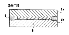
プレス成形により所望の板厚に変形された後は、温度Tg以下まで冷却する(図2における期間D)。冷却のために、金型1a,1bの裏面に水冷ジャケット3a,3bを押し付ける。水冷ジャケット3a,3bは加熱中およびプレス中は、それぞれフラットヒータ2a,2bと非接触の状態に保持され、冷却時にはそれぞれフラットヒータ2a,2bの裏面に押し付けられるように、コントローラ30によって制御される。
(3) Cooling Step-Substrate Removal After being deformed to a desired thickness by press molding, it is cooled to a temperature Tg or lower (period D in FIG. 2). For cooling, the
冷却工程中は、成形されたガラス基板が収納されている上下金型1a,1bと規制リング4とで構成されるキャビティが閉空間になっている。したがって、浮遊ダストはキャビティ内へ侵入しない。さらに、変形が終了した後にガラスから発生するガスは微量であり無視できるため、冷却工程ではチャンバー18内を排気する必要が無い。
During the cooling step, the cavity formed by the upper and lower dies 1a and 1b accommodating the formed glass substrate and the regulating ring 4 is a closed space. Therefore, the floating dust does not enter the cavity. Further, since the gas generated from the glass after the deformation is completed is negligible and negligible, it is not necessary to exhaust the inside of the
そこで、本実施形態では冷却時間を短縮するために、上下金型1a,1bと規制リング4とで構成されるキャビティが閉空間となるプレス終了後に、窒素ガス等の不活性ガス(金型やそのコーティング剤と反応しない)をチャンバー内に急速に充填し大気圧にすることにより、水冷ジャケット3a,3b、フラットヒータ2a,2b、金型1a,1bおよび成形ガラス材質間の熱伝達率を向上させる。
Therefore, in this embodiment, in order to shorten the cooling time, an inert gas such as a nitrogen gas or the like is used after the end of the press in which the cavity formed by the upper and lower dies 1a and 1b and the regulating ring 4 becomes a closed space. (Which does not react with the coating agent) is rapidly filled into the chamber and brought to atmospheric pressure, thereby improving the heat transfer coefficient between the
金型1a,1bから水冷ジャケット3a,3bヘの伝熱において、真空雰囲気中では著しく接触熱抵抗が大きいため、冷却効率が悪い。そのためプレス終了後に、チャンバー18内の排気を停止し、不活性ガスを急速に充填して、金型1a,1bと水冷ジャケット3a,3bとの間の接触面の熱抵抗を小さくすることにより、金型1a,1bの面内温度分布の均一化と、冷却時間の短縮とを実現できる。
In the heat transfer from the
このように、不活性ガスにより大気圧雰囲気中にしたチャンバー18内で、良好な熱伝導材料でできた水冷ジャケット3a,3bを金型1a,1bまたはフラットヒータ2a,2bに押し付けて冷却および離型を行うことにより、高速かつ均一な温度冷却が可能となり、反りが少ない良質かつ低コストな基板を、高い生産性で作成することができる。
As described above, the
成形基板と上下金型1a,1bをTg以下に冷却した後、上下金型1a,1bを開いて成形基板を取り出す。成形ガラス基板は、不図示の移載機によりチャンバー18の外に取り出され、搬送機で内外周加工などの後工程に送る(図2における期間E)。
After the molded substrate and the upper and lower dies 1a and 1b are cooled to Tg or less, the upper and lower dies 1a and 1b are opened and the molded substrate is taken out. The molded glass substrate is taken out of the
以上説明したように、本実施形態では、水冷ジャケット3a,3bが駆動機構27によって上昇および下降できるようにされ、この結果、水冷ジャケット3a,3bがフラットヒータ2a,2bに対して、選択的に接触または非接触にされることができるため、金型1a,1bおよびガラス素材8の面内温度の均一性が高められ、これによって、冷却の不均一さに起因する基板の変形を抑制でき、基板の好適な平坦さを提供することができる。また面内温度の均一化は、面内温度の安定までの長時間の待機を不要とするので、冷却時間の短縮も可能となる。
As described above, in the present embodiment, the water-cooling
本実施形態では水冷ジャケット3a、3bがフラットヒータ2a、2bを介して金型1a,1bに接触するので、熱源であるフラットヒータ2a,2bを冷却することでチャンバー18内を急速に冷却できる。しかしながら、本発明では、水冷ジャケット3a、3bが金型1a,1bにダイレクトに接触するように装置を設計しても良いことに注意しなければならない。
In this embodiment, since the
また、本実施形態では、一般に材料間の熱伝達が悪い真空雰囲気中においても、金型1a,1bの外周側面に対向するように配置されたふく射式のチューブヒータ16を用いることにより、金型1a,1bを介してガラス素材8を加熱するフラットヒータ2a,2bに比し効率的に、ガラス素材8を加熱できる。このため、ガラス素材8の加熱時間を短縮することができる。
Further, in the present embodiment, even in a vacuum atmosphere in which heat transfer between materials is generally poor, by using the radiating
また本実施形態では、ガラス素材8を金型1bに乗せてから昇温が終わるまでの加熱中に雰囲気を真空に保つので、金型1a,1bの周囲の雰囲気中に浮遊するダスト数を減らすことができ、ダストによる欠陥の発生率が少なくなる。
Further, in this embodiment, the atmosphere is kept at a vacuum during the heating from the time when the
また本実施形態では、冷却を真空中で行わずに、不活性ガス雰囲気中で行うので、熱伝達が低い真空での冷却に比べて、冷却効率を向上できる。また、真空中では物質間(ここでは、金型と成形ガラス)の摩擦力が増大するが、本実施形態では、冷却を真空中でなく不活性ガス雰囲気中で行うので、離型性を向上でき、不完全な離型やガラスの割れ等の不具合発生率を減じることができる。 In the present embodiment, since the cooling is not performed in a vacuum but in an inert gas atmosphere, the cooling efficiency can be improved as compared with the cooling in a vacuum having low heat transfer. Further, the frictional force between the substances (here, the mold and the molded glass) increases in a vacuum, but in the present embodiment, the cooling is performed in an inert gas atmosphere instead of in a vacuum, so that the releasability is improved. It is possible to reduce the incidence of defects such as incomplete mold release and glass breakage.
また本実施形態では、成形基板が収納されているキャビティが閉空間になっているので、冷却中に真空排気をしなくても、雰囲気からのダストの侵入を避けることができる。 Further, in this embodiment, since the cavity in which the molded substrate is housed is a closed space, it is possible to prevent dust from entering from the atmosphere without evacuation during cooling.
また本実施形態では、昇温開始からTg以下の冷却が終了するまでを、同一の金型上で行うので、それらの工程の途中でのガラス素材8への接触または搬送工程がなくなり、チャックによる欠陥や歪みを防止し、基板形状の複雑化および欠陥の低減が可能となる。
Further, in this embodiment, since the process from the start of heating up to the end of cooling below Tg is performed on the same die, there is no need to contact or transfer the
図1に示す構成を持つ装置での水冷ジャケット3a,3bを用いた実験によると、真空雰囲気での金型1a,1bの冷却速度が10℃/minであったのに対して、窒素ガス中では24℃/minであり、冷却時にガスを充填することにより2.4倍冷却速度を向上できることを確認した。
According to an experiment using the
以上の効果により、本実施形態の方法および装置を用いれば、高密度で信頼性が高く且つ安価な記憶媒体用ガラス基板および磁気ディスクを製造することができる。 According to the above effects, the use of the method and apparatus of the present embodiment makes it possible to manufacture a high-density, highly reliable, and inexpensive glass substrate for a storage medium and a magnetic disk.
以上、本発明を具体的な実施形態を参照しながら説明してきたが、当業者であれば、本発明が開示した実施形態に限定されるものではなく、以下に添付した請求の範囲の趣旨および範囲を逸脱しない範囲の他のさまざまな修正、変更および置換および広義等価物をカバーするものであることは明白である。 As described above, the present invention has been described with reference to the specific embodiments. However, those skilled in the art are not limited to the embodiments disclosed by the present invention, and have the spirit and scope of the claims attached below. It is evident that all other modifications, changes and substitutions and broad equivalents are within the scope of the present invention.
1a,1b 金型
2a,2b フラットヒータ
3a,3b 水冷ジャケット
4 規制リング
5 プレス機
7a,7b 金型支持台
16 チューブヒータ
24 可動ステージ
27 駆動機構
30 コントローラ
1a,
Claims (9)
前記ガラス素材を前記上金型と下金型との間に配置したまま加熱する加熱工程と、
前記加熱された前記ガラス素材を前記上金型と下金型とを介してプレスし、前記上金型と下金型との成形面を精密に転写して所望の基板を成形する加圧成形工程と、
前記加圧成形工程の後、成形した前記ガラス素材を前記上金型と下金型との間に配置したまま、冷却部材を前記上金型と下金型とに接触させることにより冷却する冷却工程と、
を含み、
前記加熱工程から前記加圧成形工程の間は、前記金型と前記ガラス素材とを含む空間の雰囲気を真空に保ち、前記加圧成形工程が終了した際、前記空間に不活性ガスを充填して大気圧とし、その後前記冷却工程を行うことを特徴とする記憶媒体用ガラス基板の製造方法。 A glass material is arranged between an upper mold and a lower mold, and a method of manufacturing a glass substrate for a storage medium in which a glass substrate is press-molded,
A heating step of heating while placing the glass material between the upper mold and the lower mold,
Pressing the heated glass material through the upper mold and the lower mold, and precisely transferring a molding surface of the upper mold and the lower mold to form a desired substrate. Process and
After the pressure molding step, while the molded glass material is disposed between the upper mold and the lower mold, cooling is performed by bringing a cooling member into contact with the upper mold and the lower mold. Process and
Including
During the period from the heating step to the pressure molding step, the atmosphere of the space including the mold and the glass material is kept in a vacuum, and when the pressure molding step is completed, the space is filled with an inert gas. A method of manufacturing a glass substrate for a storage medium, wherein the cooling step is performed after the atmospheric pressure is reached.
前記冷却工程中に、前記ガラス素材の温度が、前記ガラス素材のガラス転移点以下になるまで、前記上金型と下金型とを介して前記ガラス素材を加圧する工程を含むことを特徴とする請求項1に記載の記憶媒体用ガラス基板の製造方法。 It is a manufacturing method of the glass substrate for storage media of Claim 1, Comprising:
During the cooling step, a step of pressing the glass material through the upper mold and the lower mold until the temperature of the glass material becomes equal to or lower than the glass transition point of the glass material, The method of manufacturing a glass substrate for a storage medium according to claim 1.
前記ガラス素材を、前記上金型と下金型との間に配置したまま、加熱部材により加熱する加熱手段と、
加熱された前記ガラス素材を前記上金型と下金型とを介してプレスして、前記上金型と下金型との成形面を精密に転写して所望の基板を成形する加圧成形手段と、
成形した前記ガラス素材を前記上金型と下金型との間に配置したまま、冷却部材を前記上金型と下金型とに接触させることにより、成形した前記ガラス素材を冷却する冷却手段と、
前記上金型と下金型および前記加熱部材および前記冷却部材とを収容する収容手段と、
前記収容手段で形成された空間を排気・充填する排気・ガス充填手段と、
を備え、
前記排気・ガス充填手段は、前記加圧成形手段により前記上金型と下金型とが成型用の閉空間を形成するまで排気を行い、前記加圧成形手段により前記上金型と下金型とが成型用の閉空間を形成した後に、不活性ガスを充填して大気圧とし、
前記冷却手段は、前記排気・ガス充填手段が前記不活性ガスを充填して大気圧とした後に、前記ガラス素材を冷却することを特徴とする記憶媒体用ガラス基板の製造装置。 A glass material is arranged between an upper mold and a lower mold, and in a manufacturing apparatus of a glass substrate for a storage medium that press-molds a glass substrate,
A heating unit that heats the glass material with a heating member while being disposed between the upper mold and the lower mold,
Pressing the heated glass material through the upper mold and the lower mold, and precisely transferring the molding surfaces of the upper mold and the lower mold to form a desired substrate. Means,
Cooling means for cooling the formed glass material by bringing a cooling member into contact with the upper and lower molds while the formed glass material is disposed between the upper mold and the lower mold. When,
A housing unit for housing the upper mold and the lower mold, and the heating member and the cooling member,
Exhaust / gas filling means for exhausting / filling the space formed by the housing means,
With
The exhaust / gas filling means exhausts gas by the pressure molding means until the upper mold and the lower mold form a closed space for molding, and the upper mold and the lower metal mold are formed by the pressure molding means. After the mold forms a closed space for molding, it is filled with inert gas to atmospheric pressure,
An apparatus for manufacturing a glass substrate for a storage medium, wherein the cooling means cools the glass material after the exhaust / gas filling means fills the inert gas to atmospheric pressure.
前記冷却手段は、前記上金型と下金型の前記成形面と反対側の面との接触および非接触が可能な上下の水冷ジャケットを備え、
前記冷却は、前記上下の水冷ジャケットを前記上金型と下金型の前記成形面と反対側の面に接触させることにより行うことを特徴とする記憶媒体用ガラス基板の製造装置。 It is a manufacturing apparatus of the glass substrate for storage media according to claim 5,
The cooling means includes upper and lower water cooling jackets capable of contacting and non-contacting the upper mold and the lower mold with a surface opposite to the molding surface,
The apparatus for manufacturing a glass substrate for a storage medium, wherein the cooling is performed by bringing the upper and lower water cooling jackets into contact with surfaces of the upper mold and the lower mold opposite to the molding surface.
前記加熱手段は、前記上金型と下金型の周囲に配置されたふく射ヒータを含むことを特徴とする記憶媒体用ガラス基板の製造装置。 An apparatus for manufacturing a glass substrate for a storage medium according to claim 5, wherein:
The apparatus for manufacturing a glass substrate for a storage medium, wherein the heating means includes a radiation heater disposed around the upper mold and the lower mold.
A storage medium comprising the glass substrate for a storage medium according to claim 8.
Priority Applications (4)
| Application Number | Priority Date | Filing Date | Title |
|---|---|---|---|
| JP2003394581A JP2004196651A (en) | 2002-12-04 | 2003-11-25 | Method and apparatus for manufacturing glass substrate for storage medium, glass substrate for storage medium, and storage medium |
| MYPI20034605A MY148627A (en) | 2002-12-04 | 2003-12-02 | Method and apparatus for manufacturing glass substrate for storage medium, glass substrate for storage medium, and storage medium |
| US10/725,446 US7313930B2 (en) | 2002-12-04 | 2003-12-03 | Method and apparatus for manufacturing glass substrate for storage medium |
| SG200307141A SG126739A1 (en) | 2002-12-04 | 2003-12-03 | Method and apparatus for manufacturing glass substrate for storage medium, glass substrate for storage medium, and storage medium |
Applications Claiming Priority (2)
| Application Number | Priority Date | Filing Date | Title |
|---|---|---|---|
| JP2002352540 | 2002-12-04 | ||
| JP2003394581A JP2004196651A (en) | 2002-12-04 | 2003-11-25 | Method and apparatus for manufacturing glass substrate for storage medium, glass substrate for storage medium, and storage medium |
Publications (1)
| Publication Number | Publication Date |
|---|---|
| JP2004196651A true JP2004196651A (en) | 2004-07-15 |
Family
ID=32716279
Family Applications (1)
| Application Number | Title | Priority Date | Filing Date |
|---|---|---|---|
| JP2003394581A Withdrawn JP2004196651A (en) | 2002-12-04 | 2003-11-25 | Method and apparatus for manufacturing glass substrate for storage medium, glass substrate for storage medium, and storage medium |
Country Status (4)
| Country | Link |
|---|---|
| US (1) | US7313930B2 (en) |
| JP (1) | JP2004196651A (en) |
| MY (1) | MY148627A (en) |
| SG (1) | SG126739A1 (en) |
Cited By (9)
| Publication number | Priority date | Publication date | Assignee | Title |
|---|---|---|---|---|
| JP2007112010A (en) * | 2005-10-20 | 2007-05-10 | Olympus Corp | Method and apparatus for molding thermoplastic material |
| WO2011080913A1 (en) * | 2009-12-29 | 2011-07-07 | Hoya株式会社 | Method for manufacturing magnetic-disk glass substrate, and magnetic-disk glass substrate |
| WO2011080912A1 (en) * | 2009-12-29 | 2011-07-07 | Hoya株式会社 | Method for manufacturing magnetic-disk glass substrate, and magnetic-disk glass substrate |
| WO2012147372A1 (en) * | 2011-04-27 | 2012-11-01 | Hoya株式会社 | Method for producing glass blank for magnetic disc, method for producing glass substrate for magnetic disc, and glass blank for magnetic disc |
| WO2013100152A1 (en) * | 2011-12-29 | 2013-07-04 | Hoya株式会社 | Method for manufacturing glass blank for magnetic disk and method for manufacturing glass substrate for magnetic disk |
| US8869559B2 (en) | 2011-01-31 | 2014-10-28 | Hoya Corporation | Method of manufacturing a glass substrate for magnetic disk |
| US8973404B2 (en) | 2010-03-31 | 2015-03-10 | Hoya Corporation | Manufacturing method of glass substrate for magnetic disk, manufacturing method of glass blank, glass substrate for magnetic disk, and glass blank |
| JP2016216355A (en) * | 2011-04-21 | 2016-12-22 | Hoya株式会社 | Glass blank |
| CN113891867A (en) * | 2019-05-30 | 2022-01-04 | 矢崎能源系统公司 | Method for producing insulating glass, and insulating glass |
Families Citing this family (10)
| Publication number | Priority date | Publication date | Assignee | Title |
|---|---|---|---|---|
| EP1600427B8 (en) * | 2003-03-03 | 2012-11-21 | Olympus Corporation | Glass base material working method and stress applicator |
| JP4758771B2 (en) * | 2006-01-19 | 2011-08-31 | 富士フイルム株式会社 | Mold for molding |
| JP4758772B2 (en) * | 2006-01-19 | 2011-08-31 | 富士フイルム株式会社 | Mold for molding and molding method |
| DE102007041851A1 (en) * | 2007-09-03 | 2009-03-05 | Robert Bosch Gmbh | Laser device for the ignition device of an internal combustion engine |
| US8806895B2 (en) * | 2010-12-09 | 2014-08-19 | Hoya Corporation | Manufacturing method for a glass substrate for magnetic disk |
| DE102013003224A1 (en) * | 2013-02-27 | 2014-08-28 | Docter Optics Se | Method for pressing an optical lens element |
| US10406556B2 (en) | 2013-10-14 | 2019-09-10 | United Technologies Corporation | Assembly and method for transfer molding |
| WO2015108579A2 (en) * | 2013-10-14 | 2015-07-23 | United Technologies Corporation | Assembly and method for transfer molding |
| JP2017036175A (en) * | 2015-08-10 | 2017-02-16 | Hoya株式会社 | Molding equipment of optical element, and molding method for optical element |
| CN113277713B (en) * | 2021-06-25 | 2022-02-15 | 成都光明光电有限责任公司 | Glass forming device and method for forming large-diameter neodymium-doped phosphate laser glass |
Family Cites Families (24)
| Publication number | Priority date | Publication date | Assignee | Title |
|---|---|---|---|---|
| US3973942A (en) * | 1972-10-20 | 1976-08-10 | Pilkington Brothers Limited | Method of moulding and tempering glass articles |
| JPS6345137A (en) | 1986-08-13 | 1988-02-26 | Olympus Optical Co Ltd | Production apparatus for optical lens |
| JPS6395131A (en) | 1986-10-13 | 1988-04-26 | Matsushita Electric Ind Co Ltd | Glass-pressing apparatus |
| US5202156A (en) * | 1988-08-16 | 1993-04-13 | Canon Kabushiki Kaisha | Method of making an optical element mold with a hard carbon film |
| JPH0255240A (en) * | 1988-08-17 | 1990-02-23 | Asahi Glass Co Ltd | Method for bending raw glass sheet for laminated glass and apparatus therefor |
| JPH0292834A (en) * | 1988-09-28 | 1990-04-03 | Hitachi Ltd | glass lens molding machine |
| JP2669476B2 (en) * | 1989-12-06 | 1997-10-27 | キヤノン株式会社 | Optical element manufacturing method |
| JPH0437613A (en) | 1990-05-30 | 1992-02-07 | Olympus Optical Co Ltd | Method and device for forming optical element |
| GB2248065B (en) * | 1990-09-07 | 1994-03-16 | Marconi Gec Ltd | Optical storage devices |
| US5215566A (en) * | 1991-01-18 | 1993-06-01 | Canon Kabushiki Kaisha | Method of manufacturing optical element |
| JP2815057B2 (en) * | 1992-06-08 | 1998-10-27 | キヤノン株式会社 | Mold for molding optical element, method for producing the same, optical element and lens |
| JP3501580B2 (en) * | 1995-04-20 | 2004-03-02 | キヤノン株式会社 | Optical element molding method and molding apparatus |
| US5987922A (en) * | 1997-05-19 | 1999-11-23 | Hoya Corporation | Manufacturing method for molded glass articles |
| JPH10330121A (en) | 1997-05-28 | 1998-12-15 | Toshiba Mach Co Ltd | Molding of optical element and apparatus therefor |
| JP2000063132A (en) | 1998-08-11 | 2000-02-29 | Toshiba Mach Co Ltd | Apparatus for molding glass element |
| JP2000351635A (en) | 1999-06-14 | 2000-12-19 | Toshiba Mach Co Ltd | Apparatus for producing formed glass substrate |
| MY128559A (en) * | 2000-07-21 | 2007-02-28 | Matsushita Electric Industrial Co Ltd | Molded glass substrate for magnetic disk and method for manufacturing the same |
| JP2002187727A (en) * | 2000-12-18 | 2002-07-05 | Matsushita Electric Ind Co Ltd | Glass substrate manufacturing method and glass substrate molding die |
| JP4730806B2 (en) * | 2002-03-26 | 2011-07-20 | Hoya株式会社 | Glass optical element molding apparatus and molding method |
| JP2004074271A (en) * | 2002-06-20 | 2004-03-11 | Sumitomo Heavy Ind Ltd | Press equipment |
| JP4133024B2 (en) * | 2002-06-24 | 2008-08-13 | 東芝機械株式会社 | Glass molding apparatus and molding method |
| CN100419468C (en) * | 2004-02-12 | 2008-09-17 | Hoya株式会社 | Apparatus and method for manufacturing glass optical element and glass optical element manufactured thereby |
| JP4490761B2 (en) * | 2004-08-17 | 2010-06-30 | Hoya株式会社 | Mold press mold and optical element manufacturing method |
| JP4566673B2 (en) * | 2004-09-29 | 2010-10-20 | キヤノン株式会社 | Optical element molding method and apparatus |
-
2003
- 2003-11-25 JP JP2003394581A patent/JP2004196651A/en not_active Withdrawn
- 2003-12-02 MY MYPI20034605A patent/MY148627A/en unknown
- 2003-12-03 US US10/725,446 patent/US7313930B2/en not_active Expired - Fee Related
- 2003-12-03 SG SG200307141A patent/SG126739A1/en unknown
Cited By (18)
| Publication number | Priority date | Publication date | Assignee | Title |
|---|---|---|---|---|
| JP2007112010A (en) * | 2005-10-20 | 2007-05-10 | Olympus Corp | Method and apparatus for molding thermoplastic material |
| US8733129B2 (en) | 2009-12-29 | 2014-05-27 | Hoya Corporation | Glass substrate for magnetic disk and manufacturing method thereof |
| US9003834B2 (en) | 2009-12-29 | 2015-04-14 | Hoya Corporation | Glass substrate for magnetic disk and manufacturing method thereof |
| JP2011154772A (en) * | 2009-12-29 | 2011-08-11 | Hoya Corp | Manufacturing method of glass substrate for magnetic disk, and the glass substrate for magnetic disk |
| JP2011154773A (en) * | 2009-12-29 | 2011-08-11 | Hoya Corp | Method for manufacturing magnetic disk glass substrate, and magnetic disk glass substrate |
| JP2012133882A (en) * | 2009-12-29 | 2012-07-12 | Hoya Corp | Method for manufacturing magnetic disk glass substrate and magnetic disk plate-shaped glass blank |
| WO2011080913A1 (en) * | 2009-12-29 | 2011-07-07 | Hoya株式会社 | Method for manufacturing magnetic-disk glass substrate, and magnetic-disk glass substrate |
| WO2011080912A1 (en) * | 2009-12-29 | 2011-07-07 | Hoya株式会社 | Method for manufacturing magnetic-disk glass substrate, and magnetic-disk glass substrate |
| US9085479B2 (en) | 2009-12-29 | 2015-07-21 | Hoya Corporation | Glass substrate for magnetic disk and manufacturing method thereof |
| US8973404B2 (en) | 2010-03-31 | 2015-03-10 | Hoya Corporation | Manufacturing method of glass substrate for magnetic disk, manufacturing method of glass blank, glass substrate for magnetic disk, and glass blank |
| US8869559B2 (en) | 2011-01-31 | 2014-10-28 | Hoya Corporation | Method of manufacturing a glass substrate for magnetic disk |
| JP2016216355A (en) * | 2011-04-21 | 2016-12-22 | Hoya株式会社 | Glass blank |
| WO2012147372A1 (en) * | 2011-04-27 | 2012-11-01 | Hoya株式会社 | Method for producing glass blank for magnetic disc, method for producing glass substrate for magnetic disc, and glass blank for magnetic disc |
| JPWO2012147372A1 (en) * | 2011-04-27 | 2014-07-28 | Hoya株式会社 | Method for manufacturing glass blank for magnetic disk, method for manufacturing glass substrate for magnetic disk, glass blank for magnetic disk |
| US9409809B2 (en) | 2011-04-27 | 2016-08-09 | Hoya Corporation | Method for manufacturing glass blank for magnetic disk, method for manufacturing glass substrate for magnetic disk, glass blank for magnetic disk |
| WO2013100152A1 (en) * | 2011-12-29 | 2013-07-04 | Hoya株式会社 | Method for manufacturing glass blank for magnetic disk and method for manufacturing glass substrate for magnetic disk |
| CN113891867A (en) * | 2019-05-30 | 2022-01-04 | 矢崎能源系统公司 | Method for producing insulating glass, and insulating glass |
| CN113891867B (en) * | 2019-05-30 | 2023-11-21 | 矢崎能源系统公司 | Manufacturing method of insulating glass and insulating glass |
Also Published As
| Publication number | Publication date |
|---|---|
| US7313930B2 (en) | 2008-01-01 |
| SG126739A1 (en) | 2006-11-29 |
| MY148627A (en) | 2013-05-15 |
| US20040134232A1 (en) | 2004-07-15 |
Similar Documents
| Publication | Publication Date | Title |
|---|---|---|
| US7313930B2 (en) | Method and apparatus for manufacturing glass substrate for storage medium | |
| JP2003103331A (en) | Manufacturing method for metallic part and manufacturing device therefor | |
| US5188652A (en) | Machine for molding optical element | |
| TW555703B (en) | Apparatus and method for forming silica glass elements | |
| JP2001180946A (en) | Method for forming optical glass element and forming apparatus for optical glass with method | |
| JP4059008B2 (en) | Press molding method and press molding apparatus | |
| JP2005255513A (en) | Apparatus and method for producing glass optical element and glass optical element produced thereby | |
| JP2002046070A (en) | Whetstone manufacturing method and device | |
| JP3746570B2 (en) | Method for manufacturing optical element with lens barrel | |
| JP4445841B2 (en) | Optical element molding equipment | |
| JP2946003B2 (en) | Method and apparatus for molding optical element | |
| JP3585260B2 (en) | Apparatus and method for manufacturing optical element | |
| JP3187902B2 (en) | Glass optical element molding method | |
| JP2000169159A (en) | Device and process for forming glass element | |
| JP4358406B2 (en) | Optical element molding apparatus and molding method | |
| JP4759362B2 (en) | Optical element manufacturing apparatus and manufacturing method | |
| JP2001335330A (en) | Method for forming optical elements | |
| JP2008137836A (en) | Molding apparatus and method for producing molded article | |
| JP2003137568A (en) | Apparatus for molding glass element | |
| JP3184585B2 (en) | Mold for glass optical element | |
| JP3752651B2 (en) | Method and apparatus for forming rod-shaped glass element | |
| JP4203289B2 (en) | Quartz glass element molding apparatus and molding method | |
| JP6667358B2 (en) | Glass substrate generator | |
| JP4347629B2 (en) | Glass element molding equipment | |
| JP5303287B2 (en) | Glass substrate molding apparatus and glass substrate molding method |
Legal Events
| Date | Code | Title | Description |
|---|---|---|---|
| A621 | Written request for application examination |
Free format text: JAPANESE INTERMEDIATE CODE: A621 Effective date: 20060728 |
|
| A761 | Written withdrawal of application |
Free format text: JAPANESE INTERMEDIATE CODE: A761 Effective date: 20090119 |