JP2004197943A - シリンダ・ピストン装置 - Google Patents
シリンダ・ピストン装置 Download PDFInfo
- Publication number
- JP2004197943A JP2004197943A JP2003416399A JP2003416399A JP2004197943A JP 2004197943 A JP2004197943 A JP 2004197943A JP 2003416399 A JP2003416399 A JP 2003416399A JP 2003416399 A JP2003416399 A JP 2003416399A JP 2004197943 A JP2004197943 A JP 2004197943A
- Authority
- JP
- Japan
- Prior art keywords
- cylinder
- piston
- working chamber
- chamber
- stepped
- Prior art date
- Legal status (The legal status is an assumption and is not a legal conclusion. Google has not performed a legal analysis and makes no representation as to the accuracy of the status listed.)
- Granted
Links
- 238000006073 displacement reaction Methods 0.000 claims abstract description 16
- 239000012530 fluid Substances 0.000 claims abstract description 10
- 230000002093 peripheral effect Effects 0.000 claims description 20
- 230000006835 compression Effects 0.000 claims description 10
- 238000007906 compression Methods 0.000 claims description 10
- 238000007789 sealing Methods 0.000 claims description 7
- 229920001971 elastomer Polymers 0.000 claims description 4
- 239000000806 elastomer Substances 0.000 claims description 4
- 239000013536 elastomeric material Substances 0.000 claims description 3
- 230000000149 penetrating effect Effects 0.000 claims description 2
- 239000010720 hydraulic oil Substances 0.000 description 5
- 239000007788 liquid Substances 0.000 description 3
- 238000004519 manufacturing process Methods 0.000 description 3
- 239000003921 oil Substances 0.000 description 3
- 230000008878 coupling Effects 0.000 description 2
- 238000010168 coupling process Methods 0.000 description 2
- 238000005859 coupling reaction Methods 0.000 description 2
- 239000000463 material Substances 0.000 description 2
- 230000003139 buffering effect Effects 0.000 description 1
- 238000010276 construction Methods 0.000 description 1
- 238000010586 diagram Methods 0.000 description 1
- 238000005304 joining Methods 0.000 description 1
- 238000004904 shortening Methods 0.000 description 1
- 230000007704 transition Effects 0.000 description 1
- 238000003466 welding Methods 0.000 description 1
Images


Classifications
-
- F—MECHANICAL ENGINEERING; LIGHTING; HEATING; WEAPONS; BLASTING
- F16—ENGINEERING ELEMENTS AND UNITS; GENERAL MEASURES FOR PRODUCING AND MAINTAINING EFFECTIVE FUNCTIONING OF MACHINES OR INSTALLATIONS; THERMAL INSULATION IN GENERAL
- F16F—SPRINGS; SHOCK-ABSORBERS; MEANS FOR DAMPING VIBRATION
- F16F9/00—Springs, vibration-dampers, shock-absorbers, or similarly-constructed movement-dampers using a fluid or the equivalent as damping medium
- F16F9/32—Details
- F16F9/50—Special means providing automatic damping adjustment, i.e. self-adjustment of damping by particular sliding movements of a valve element, other than flexions or displacement of valve discs; Special means providing self-adjustment of spring characteristics
- F16F9/512—Means responsive to load action, i.e. static load on the damper or dynamic fluid pressure changes in the damper, e.g. due to changes in velocity
-
- E—FIXED CONSTRUCTIONS
- E05—LOCKS; KEYS; WINDOW OR DOOR FITTINGS; SAFES
- E05C—BOLTS OR FASTENING DEVICES FOR WINGS, SPECIALLY FOR DOORS OR WINDOWS
- E05C17/00—Devices for holding wings open; Devices for limiting opening of wings or for holding wings open by a movable member extending between frame and wing; Braking devices, stops or buffers, combined therewith
- E05C17/02—Devices for holding wings open; Devices for limiting opening of wings or for holding wings open by a movable member extending between frame and wing; Braking devices, stops or buffers, combined therewith by mechanical means
- E05C17/04—Devices for holding wings open; Devices for limiting opening of wings or for holding wings open by a movable member extending between frame and wing; Braking devices, stops or buffers, combined therewith by mechanical means with a movable bar or equivalent member extending between frame and wing
- E05C17/30—Devices for holding wings open; Devices for limiting opening of wings or for holding wings open by a movable member extending between frame and wing; Braking devices, stops or buffers, combined therewith by mechanical means with a movable bar or equivalent member extending between frame and wing of extensible, e.g. telescopic, construction
- E05C17/305—Devices for holding wings open; Devices for limiting opening of wings or for holding wings open by a movable member extending between frame and wing; Braking devices, stops or buffers, combined therewith by mechanical means with a movable bar or equivalent member extending between frame and wing of extensible, e.g. telescopic, construction with hydraulic locks
-
- F—MECHANICAL ENGINEERING; LIGHTING; HEATING; WEAPONS; BLASTING
- F16—ENGINEERING ELEMENTS AND UNITS; GENERAL MEASURES FOR PRODUCING AND MAINTAINING EFFECTIVE FUNCTIONING OF MACHINES OR INSTALLATIONS; THERMAL INSULATION IN GENERAL
- F16F—SPRINGS; SHOCK-ABSORBERS; MEANS FOR DAMPING VIBRATION
- F16F9/00—Springs, vibration-dampers, shock-absorbers, or similarly-constructed movement-dampers using a fluid or the equivalent as damping medium
- F16F9/06—Springs, vibration-dampers, shock-absorbers, or similarly-constructed movement-dampers using a fluid or the equivalent as damping medium using both gas and liquid
- F16F9/064—Units characterised by the location or shape of the expansion chamber
-
- F—MECHANICAL ENGINEERING; LIGHTING; HEATING; WEAPONS; BLASTING
- F16—ENGINEERING ELEMENTS AND UNITS; GENERAL MEASURES FOR PRODUCING AND MAINTAINING EFFECTIVE FUNCTIONING OF MACHINES OR INSTALLATIONS; THERMAL INSULATION IN GENERAL
- F16F—SPRINGS; SHOCK-ABSORBERS; MEANS FOR DAMPING VIBRATION
- F16F9/00—Springs, vibration-dampers, shock-absorbers, or similarly-constructed movement-dampers using a fluid or the equivalent as damping medium
- F16F9/06—Springs, vibration-dampers, shock-absorbers, or similarly-constructed movement-dampers using a fluid or the equivalent as damping medium using both gas and liquid
- F16F9/066—Units characterised by the partition, baffle or like element
- F16F9/067—Partitions of the piston type, e.g. sliding pistons
-
- F—MECHANICAL ENGINEERING; LIGHTING; HEATING; WEAPONS; BLASTING
- F16—ENGINEERING ELEMENTS AND UNITS; GENERAL MEASURES FOR PRODUCING AND MAINTAINING EFFECTIVE FUNCTIONING OF MACHINES OR INSTALLATIONS; THERMAL INSULATION IN GENERAL
- F16F—SPRINGS; SHOCK-ABSORBERS; MEANS FOR DAMPING VIBRATION
- F16F9/00—Springs, vibration-dampers, shock-absorbers, or similarly-constructed movement-dampers using a fluid or the equivalent as damping medium
- F16F9/32—Details
- F16F9/50—Special means providing automatic damping adjustment, i.e. self-adjustment of damping by particular sliding movements of a valve element, other than flexions or displacement of valve discs; Special means providing self-adjustment of spring characteristics
- F16F9/516—Special means providing automatic damping adjustment, i.e. self-adjustment of damping by particular sliding movements of a valve element, other than flexions or displacement of valve discs; Special means providing self-adjustment of spring characteristics resulting in the damping effects during contraction being different from the damping effects during extension, i.e. responsive to the direction of movement
Landscapes
- Engineering & Computer Science (AREA)
- General Engineering & Computer Science (AREA)
- Mechanical Engineering (AREA)
- Physics & Mathematics (AREA)
- Fluid Mechanics (AREA)
- Fluid-Damping Devices (AREA)
- Actuator (AREA)
Abstract
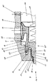
【解決手段】ピストン2が,環状シール30によりシリンダ1に対して液密状態で摺動接触してシリンダ内スペースを,それぞれ作動流体が充填される第1作動室3及び第2作動室4に分割する。ピストンロッド5が,シリンダの少なくとも一方の端壁を液密に貫通して外部まで突出する。第1チェック弁の弁体が閉鎖方向に向けて圧力負荷され,第1作動室3の内圧下で開放して第1作動室を第2作動室4に接続する。第2チェック弁26の弁体が閉鎖方向に向けて圧力負荷され,第2作動室の内圧下で開放して第2作動室を第1作動室に接続する。本発明では,第1チェック弁及び/又は第2チェック弁の弁体に関して,作動室の圧力が作用する受圧面積を,当該弁体の開放ストローク変位の間に増加させる。
【選択図】図1
Description
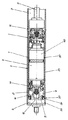
2 ピストン
3 第1作動室
4 第2作動室
5 ピストンロッド
6 容量調整手段
7 第1チェック弁
8 第2チェック弁
9 底部
10 最小段部
11 段付き孔
12 連結孔
13 第2段部
14 流路
15 スリット
16,17 最大段部
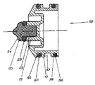
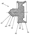
18,18’,18” 段付きプランジャ
19,19’ 小径段部
20 弁体
21 閉鎖面
22 弁座
23 シャフト
24 有底孔
25 シールリング
26 チェック弁
27 圧縮コイルばね
28 絞り開口
29 シリンダ室
30 環状シール
31 シールリップ
32 内壁
33,34 環状溝
35,36 シールリング
37 環状溝
38 半径方向通路
39 流入開口
40 容量調整室
41 緩衝室
42 緩衝開口
43,44,45 シールリップ
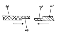
46,47,48,49 環状段部
50 係止開口
51 係止突部
52 延長部
53 環状スリット
54 延長部
55 環状カラー
56 環状スリット
57 制御溝
Claims (27)
- 閉鎖端壁を有するシリンダと,該シリンダ内に軸線方向変位可能に配置されたピストンとを具え,該ピストンが環状シールによりシリンダに対して液密に摺動接触してシリンダ内スペースを,それぞれ作動流体が充填される第1作動室及び第2作動室に分割し,さらに,該ピストンに結合され,シリンダ内スペースを貫通して延在すると共に,シリンダの少なくとも一方の端壁を液密に貫通して外部まで突出するピストンロッドと,閉鎖方向に向けて圧力負荷され,第1作動室の内圧下で開放して第1作動室を第2作動室に接続する弁体を有する第1チェック弁と,同様に閉鎖方向に向けて圧力負荷され,第2作動室の内圧下で開放して第2作動室を第1作動室に接続する弁体を有する第2チェック弁とを具え,前記第1チェック弁及び/又は第2チェック弁(26)の弁体における,作動室(3,4)の内圧が作用する受圧面積を,該弁体の開放ストローク変位の間に増加させることを特徴とするシリンダ・ピストン装置。
- 請求項1記載の装置において,前記第1チェック弁及び/又は第2チェック弁(26)の弁体を段付きプランジャ(18,18’)として構成し,該プランジャ(18,18’)を対応する段付き孔(11)内に変位可能に配置し,該プランジャの段部(17,19)に端面側で作動室(3,4)の内圧が作用する受圧面を設け,閉鎖位置での最小段部(19)に対する圧力負荷に始まり,プランジャ(18,18’)の開放ストローク変位量の増大に応じてプランジャ(18,18’)の他の段部(17)にも圧力を負荷することを特徴とするシリンダ・ピストン装置。
- 請求項1又は2に記載の装置において,作動室(3,4)の内圧が負荷されるチェック弁(26)の最小受圧面を,シート弁における弁体(20)で構成することを特徴とするシリンダ・ピストン装置。
- 請求項3記載の装置において,前記チェック弁(26)の弁体(20)を段付きプランジャ(18,18’)における最小段部(19)の端面側で構成し,該弁体(20)を,作動室(3,4)に接続する段付き孔(11)の最小段部(10)における開口部に対して接離可能とし,該開口部によりチェック弁(26)の弁座(22)を形成することを特徴とするシリンダ・ピストン装置。
- 請求項3又は4に記載の装置において,前記弁体(20)に円錐状の閉鎖面(21)を設け,該閉鎖面(21)を弁座(22)上に当接可能とすることを特徴とするシリンダ・ピストン装置。
- 請求項3〜5の何れか一項に記載の装置において,前記閉鎖部分(20)が,エラストマ製の閉鎖面(21)を有することを特徴とするシリンダ・ピストン装置。
- 請求項2〜6の何れか一項に記載の装置において,前記段付き孔(11)における少なくとも1つの段部(13)に,次に大きな段部(16)への接続部を設け,一定の開放ストローク変位量に到達すると,段付き孔(11)の次に大きな段部(16)への接続部を開放可能としたことを特徴とするシリンダ・ピストン装置。
- 請求項7記載の装置において,前記段付きプランジャ(18,18’)の少なくとも1つの段部(17,19)により摺動弁のスライダを形成し,該スライダにより,段付き孔(11)と半径方向に接続する,対応する接続部を開閉可能としたことを特徴とするシリンダ・ピストン装置。
- 請求項8記載の装置において,前記段付きプランジャ(18)の少なくとも1つの段部(17,19)が,その円筒状外周面に環状溝(33,34)を有し,前記環状溝に装着したシールリング(25,35,36)の外周領域を,段付き孔(11)における対応する段部(13,16)の内壁に対して密着させることを特徴とするシリンダ・ピストン装置。
- 請求項7〜9の何れか一項に記載の装置において,前記段付き孔(11)の最大段部(16)を,半径方向通路(38)により,シリンダ(1)の内壁(32)とピストン(2)の外周面との間に形成される環状シリンダ室(29)に接続し,該シリンダ室(29)を環状シール(30)により作動室(3,4)に対して密閉し,シリンダ室(29)の内圧により段付きプランジャ(18,18’)を開放方向に向けて変位可能とし,該半径方向通路(38)を,段付きプランジャ(18,18’)の最大段部(17)により閉鎖可能とすると共に,その最大開放ストローク変位位置で開放可能としたことを特徴とするシリンダ・ピストン装置。
- 請求項1〜10の何れか一項に記載の装置において,前記弁体をピストン(2)に係合する圧縮ばね,好適には圧縮コイルばね(27)又は皿ばねにより,閉鎖方向に向けて附勢することを特徴とするシリンダ・ピストン装置。
- 請求項2〜9の何れか一項に記載の装置において,前記段付き孔(11)の最大段部(16)により,作動室(3,4)から離れた段付きプランジャ(18,18’)の側に緩衝室(41)を形成し,該緩衝室(41)を緩衝開口(42)を経てシリンダ室(29)に接続することを特徴とするシリンダ・ピストン装置。
- 請求項12記載の装置において,前記段付きプランジャ(18,18’)を閉鎖方向に向けて変位させる際,前記緩衝室(41)を,バルブを経てシリンダ室(29)に接続することを特徴とするシリンダ・ピストン装置。
- 請求項13記載の装置において,段付きプランジャ(18)における最大段部(17)の円筒状外周面に環状溝(34)を設け,前記バルブが該環状溝(34)内に配置したシールリング(36)を具え,緩衝室(41)から離れた該シールリング(36)の側をシリンダ室(29)と接続し,該シールリング(36)によりシリンダ室(29)から緩衝室(41)へのオーバーフロー又はアンダーフローを許容することを特徴とするシリンダ・ピストン装置。
- 請求項11〜14の何れか一項に記載の装置において,前記圧縮ばねを緩衝室(41)内に配置することを特徴とするシリンダ・ピストン装置。
- 請求項2〜15の何れか一項に記載の装置において,前記段付き孔(11)の最大段部(16)を,作動室(3,4)に対向する段付きプランジャ(18,18’)の,対応する段部(17)の側で,絞り開口(28)を経てシリンダ室(29)に接続することを特徴とするシリンダ・ピストン装置。
- 請求項1〜16の何れか一項に記載の装置において,前記環状シール(30)を,ピストン(2)の円筒状外周面に設けた環状溝内に配置したことを特徴とするシリンダ・ピストン装置。
- 請求項1〜17の何れか一項に記載の装置において,前記環状シール(30)が円周方向に延在するシールリップ(31)を具え,該シールリップ(31)の先端を作動室(3,4)に向けて延在させると共にシリンダ(1)の内壁(32)に弾性接触させることを特徴とするシリンダ・ピストン装置。
- 請求項2〜18の何れか一項に記載の装置において,少なくとも1つの段付き孔(11)を,前記緩衝室(41)に至る流路(14)の貫通孔として構成し,該貫通孔内に前記段付きプランジャ(18,18’)の小径段部(19)を変位可能に配置し,該流路(14)を段付きプランジャ(18)におけるカラー領域に含まれるものとし,該カラー領域に段付きプランジャ(18)の次に大きい段部(17)を配置して前記流路(14)を包囲することを特徴とするシリンダ・ピストン装置。
- 請求項19記載の装置において,前記流路(14)の緩衝室(41)側に位置する端部領域に,半径方向のスリット(15)を形成し,該スリット(15)を介して,前記段付き孔(11)における2つの段部(13,16)間を半径方向に接続することを特徴とするシリンダ・ピストン装置。
- 請求項2〜20の何れか一項に記載の装置において,前記段付きプランジャ(18’)をエラストマ材料製とし,該プランジャにおける少なくとも1つの段部(17,19)に,前記弁体(20)の閉鎖面(21)及び/又は円周方向に延在するシールリップ(43,44,45)を一体的に成形したことを特徴とするシリンダ・ピストン装置。
- 請求項1〜21の何れか一応に記載の装置において,前記ピストン(2)の一側にピストンロッド(5)を配置し,該ピストンロッド(5)側に位置する作動室(3)からの排出量と対比して,ピストンロッド(5)から離れた側に位置する作動室(4)からの排出量が多量である場合に,その余剰の排出量を受容するための容量調整室(40)を設けたことを特徴とするシリンダ・ピストン装置。
- 請求項22記載の装置において,前記容量調整室(40)をピストン(2)内の第1チェック弁及び第2チェック弁の間に配置すると共に,両チェック弁の間で流入開口(39)を経て前記シリンダ室(29)に接続したことを特徴とするシリンダ・ピストン装置。
- 請求項1〜23の何れか一項に記載の装置において,前記チェック弁(26)における弁体の開放ストローク変位の一部では,バルブ通路を絞り通路として機能させることを特徴とするシリンダ・ピストン装置。
- 請求項3〜24の何れか一項に記載の装置において,第1作動室(3)から第2作動室(4)への流れ方向及び/又は第2作動室(4)から第1作動室(3)への流れ方向を有する絞り通路を,シートバルブの弁座(22)の前方及び/又は後方に配置したことを特徴とするシリンダ・ピストン装置。
- 請求項4又は25に記載の装置において,前記段付きプランジャ(18”)に,弁体(20)から作動室(3,4)に向けて延在する略円筒形状の延長部(52)を設け,該延長部(52)は前記段付き孔(11)の最小段部(10)から突出させ,該延長部(52)の外周面と段付き孔(11)の最小段部(10)の内壁との間に絞り通路として機能する環状スリット(53)を形成したことを特徴とするシリンダ・ピストン装置。
- 請求項7又は25に記載の装置において,第1作動室(3)から第2作動室(4)への流れ方向及び/又は第2作動室(4)から第1作動室(3)への流れ方向において,シートバルブの弁座(22)の後方に位置する段付きプランジャ(18”)の段部(19’)に略円筒形状の延長部を設け,該延長部を,チェック弁(26)の開放方向で段付き孔(11)の第2段部(13)内に突出する同軸的な環状カラー(55)により案内し,該延長部(54)の外周面と環状カラー(55)の内壁との間に絞り通路として機能する環状スリット(56)を形成したことを特徴とするシリンダ・ピストン装置。
Applications Claiming Priority (2)
| Application Number | Priority Date | Filing Date | Title |
|---|---|---|---|
| DE10258523 | 2002-12-14 | ||
| DE10351531A DE10351531A1 (de) | 2002-12-14 | 2003-11-03 | Kolben-Zylinder-Einheit |
Publications (2)
| Publication Number | Publication Date |
|---|---|
| JP2004197943A true JP2004197943A (ja) | 2004-07-15 |
| JP3881652B2 JP3881652B2 (ja) | 2007-02-14 |
Family
ID=32327520
Family Applications (1)
| Application Number | Title | Priority Date | Filing Date |
|---|---|---|---|
| JP2003416399A Expired - Fee Related JP3881652B2 (ja) | 2002-12-14 | 2003-12-15 | シリンダ・ピストン装置 |
Country Status (5)
| Country | Link |
|---|---|
| US (1) | US7048100B2 (ja) |
| EP (1) | EP1428962B1 (ja) |
| JP (1) | JP3881652B2 (ja) |
| DE (1) | DE50302654D1 (ja) |
| ES (1) | ES2257633T3 (ja) |
Cited By (1)
| Publication number | Priority date | Publication date | Assignee | Title |
|---|---|---|---|---|
| JP2015127497A (ja) * | 2013-11-29 | 2015-07-09 | アイシン精機株式会社 | ドアチェック装置 |
Families Citing this family (7)
| Publication number | Priority date | Publication date | Assignee | Title |
|---|---|---|---|---|
| US20050256750A1 (en) * | 1999-07-01 | 2005-11-17 | American Express Travel Related Services Company, Inc. | Ticket tracking and refunding system and method |
| DE102004023557B4 (de) * | 2004-05-13 | 2006-05-04 | Stabilus Gmbh | Stufenloser hydraulischer Türfeststeller |
| US20070237661A1 (en) * | 2006-04-05 | 2007-10-11 | Tsun-Sheng Chen | Hand-operated reciprocating pump |
| US20080162196A1 (en) * | 2006-12-29 | 2008-07-03 | American Express Travel Services, Co., Inc. | System and method for centralizing and processing ticket exchange information |
| US8700435B2 (en) * | 2006-12-29 | 2014-04-15 | American Express Travel Related Services Company, Inc. | System and method for redemption and exchange of unused tickets |
| WO2008124464A1 (en) * | 2007-04-04 | 2008-10-16 | Gkn Sinter Metals, Llc. | Multi-piece thin walled powder metal cylinder liners |
| CN115288539B (zh) * | 2022-07-05 | 2024-07-26 | 南京江凯汽车零部件有限公司 | 一种液压无极限位器 |
Family Cites Families (8)
| Publication number | Priority date | Publication date | Assignee | Title |
|---|---|---|---|---|
| US4099602A (en) * | 1977-08-31 | 1978-07-11 | P. L. Porter Company | Hydraulic positioner with bidirectional detenting action |
| DE3642442C1 (en) | 1986-12-12 | 1987-08-27 | Audi Ag | Door damper and door stop for a motor-vehicle door |
| JP2811567B2 (ja) * | 1987-03-13 | 1998-10-15 | 株式会社 ニフコ | 車室内物品収納筐の開閉緩衝装置 |
| DE4239681A1 (de) * | 1992-11-26 | 1994-06-01 | Brose Fahrzeugteile | Stufenlos wirkender Türfeststeller, insbesondere für eine Fahrzeugtür |
| AU671518B2 (en) * | 1993-03-18 | 1996-08-29 | Stabilus Gmbh | A locking device for securing objects which are movable relatively to one another |
| DE4433648A1 (de) | 1994-09-21 | 1996-03-28 | Scharwaechter Gmbh Co Kg | Türfeststeller, insbesondere für Kraftwagentüren |
| DE19609040C2 (de) | 1996-03-08 | 1999-05-27 | Stabilus Gmbh | Feststellelement |
| ES2163949B2 (es) * | 1997-07-29 | 2003-07-16 | Stabilus Gmbh | Grupo cilindro-piston bloqueable. |
-
2003
- 2003-11-18 ES ES03026343T patent/ES2257633T3/es not_active Expired - Lifetime
- 2003-11-18 EP EP03026343A patent/EP1428962B1/de not_active Expired - Lifetime
- 2003-11-18 DE DE50302654T patent/DE50302654D1/de not_active Expired - Lifetime
- 2003-12-12 US US10/734,571 patent/US7048100B2/en not_active Expired - Fee Related
- 2003-12-15 JP JP2003416399A patent/JP3881652B2/ja not_active Expired - Fee Related
Cited By (1)
| Publication number | Priority date | Publication date | Assignee | Title |
|---|---|---|---|---|
| JP2015127497A (ja) * | 2013-11-29 | 2015-07-09 | アイシン精機株式会社 | ドアチェック装置 |
Also Published As
| Publication number | Publication date |
|---|---|
| JP3881652B2 (ja) | 2007-02-14 |
| US20040178034A1 (en) | 2004-09-16 |
| EP1428962A1 (de) | 2004-06-16 |
| US7048100B2 (en) | 2006-05-23 |
| DE50302654D1 (de) | 2006-05-11 |
| ES2257633T3 (es) | 2006-08-01 |
| EP1428962B1 (de) | 2006-03-15 |
Similar Documents
| Publication | Publication Date | Title |
|---|---|---|
| US11761509B2 (en) | Damping force generating mechanism and pressure shock absorber | |
| JP4048158B2 (ja) | シリンダ・ピストン装置 | |
| CN110475985B (zh) | 缓冲器 | |
| US12038063B2 (en) | Shock absorber | |
| CN102575739B (zh) | 线性减震器 | |
| JP2008267489A (ja) | 流体圧緩衝器 | |
| CN101589254B (zh) | 滑阀 | |
| US20210301928A1 (en) | Valve arrangement and switching valve for regulating a mass flow | |
| EP3961074B1 (en) | Relief valve | |
| JP3881652B2 (ja) | シリンダ・ピストン装置 | |
| US10287973B2 (en) | Hydraulic valve and connection rod with the hydraulic valve | |
| KR20070038535A (ko) | 개선된 효율을 갖는 피스톤 펌프 | |
| KR102554152B1 (ko) | 감쇠력 조정식 완충기 | |
| JP2021021438A (ja) | 減衰力調整式緩衝器 | |
| JP7129385B2 (ja) | 減衰力調整式緩衝器 | |
| JP6796291B2 (ja) | エアシリンダ | |
| KR102627961B1 (ko) | 감쇠력 조정식 완충기 | |
| JP3410526B2 (ja) | 吐出弁 | |
| JP7320481B2 (ja) | 緩衝器 | |
| JP4018659B2 (ja) | リリーフ弁装置 | |
| JP2023002350A (ja) | 増圧装置 | |
| WO2022215400A1 (ja) | 緩衝器 | |
| JP2021021436A (ja) | 減衰力調整式緩衝器 | |
| US11953099B2 (en) | Valve arrangement and switching valve for regulating a mass flow | |
| JP2014532577A (ja) | 車両ブレーキシステムのための液圧操作式のコントロールバルブ、およびこれに対応する車両ブレーキシステム |
Legal Events
| Date | Code | Title | Description |
|---|---|---|---|
| A131 | Notification of reasons for refusal |
Free format text: JAPANESE INTERMEDIATE CODE: A131 Effective date: 20060131 |
|
| A601 | Written request for extension of time |
Free format text: JAPANESE INTERMEDIATE CODE: A601 Effective date: 20060428 |
|
| A602 | Written permission of extension of time |
Free format text: JAPANESE INTERMEDIATE CODE: A602 Effective date: 20060508 |
|
| A521 | Request for written amendment filed |
Free format text: JAPANESE INTERMEDIATE CODE: A523 Effective date: 20060731 |
|
| TRDD | Decision of grant or rejection written | ||
| A01 | Written decision to grant a patent or to grant a registration (utility model) |
Free format text: JAPANESE INTERMEDIATE CODE: A01 Effective date: 20061107 |
|
| A61 | First payment of annual fees (during grant procedure) |
Free format text: JAPANESE INTERMEDIATE CODE: A61 Effective date: 20061110 |
|
| R150 | Certificate of patent or registration of utility model |
Free format text: JAPANESE INTERMEDIATE CODE: R150 |
|
| FPAY | Renewal fee payment (event date is renewal date of database) |
Free format text: PAYMENT UNTIL: 20091117 Year of fee payment: 3 |
|
| FPAY | Renewal fee payment (event date is renewal date of database) |
Free format text: PAYMENT UNTIL: 20101117 Year of fee payment: 4 |
|
| FPAY | Renewal fee payment (event date is renewal date of database) |
Free format text: PAYMENT UNTIL: 20111117 Year of fee payment: 5 |
|
| FPAY | Renewal fee payment (event date is renewal date of database) |
Free format text: PAYMENT UNTIL: 20121117 Year of fee payment: 6 |
|
| FPAY | Renewal fee payment (event date is renewal date of database) |
Free format text: PAYMENT UNTIL: 20131117 Year of fee payment: 7 |
|
| R250 | Receipt of annual fees |
Free format text: JAPANESE INTERMEDIATE CODE: R250 |
|
| R250 | Receipt of annual fees |
Free format text: JAPANESE INTERMEDIATE CODE: R250 |
|
| R250 | Receipt of annual fees |
Free format text: JAPANESE INTERMEDIATE CODE: R250 |
|
| LAPS | Cancellation because of no payment of annual fees |