JP2004198101A - Oil separator - Google Patents
Oil separator Download PDFInfo
- Publication number
- JP2004198101A JP2004198101A JP2003407166A JP2003407166A JP2004198101A JP 2004198101 A JP2004198101 A JP 2004198101A JP 2003407166 A JP2003407166 A JP 2003407166A JP 2003407166 A JP2003407166 A JP 2003407166A JP 2004198101 A JP2004198101 A JP 2004198101A
- Authority
- JP
- Japan
- Prior art keywords
- oil
- wall
- discharge pipe
- oil separator
- separator according
- Prior art date
- Legal status (The legal status is an assumption and is not a legal conclusion. Google has not performed a legal analysis and makes no representation as to the accuracy of the status listed.)
- Granted
Links
- 239000003507 refrigerant Substances 0.000 claims abstract description 24
- 230000002265 prevention Effects 0.000 claims abstract description 6
- 230000005484 gravity Effects 0.000 claims description 8
- 230000002093 peripheral effect Effects 0.000 claims 7
- 230000004888 barrier function Effects 0.000 claims 1
- 238000000926 separation method Methods 0.000 description 6
- 239000000203 mixture Substances 0.000 description 3
- 238000005057 refrigeration Methods 0.000 description 3
- 238000004378 air conditioning Methods 0.000 description 2
- 230000006835 compression Effects 0.000 description 1
- 238000007906 compression Methods 0.000 description 1
- 238000005461 lubrication Methods 0.000 description 1
- 238000000034 method Methods 0.000 description 1
- 238000012986 modification Methods 0.000 description 1
- 230000004048 modification Effects 0.000 description 1
- 238000003466 welding Methods 0.000 description 1
Images


Classifications
-
- F—MECHANICAL ENGINEERING; LIGHTING; HEATING; WEAPONS; BLASTING
- F25—REFRIGERATION OR COOLING; COMBINED HEATING AND REFRIGERATION SYSTEMS; HEAT PUMP SYSTEMS; MANUFACTURE OR STORAGE OF ICE; LIQUEFACTION SOLIDIFICATION OF GASES
- F25B—REFRIGERATION MACHINES, PLANTS OR SYSTEMS; COMBINED HEATING AND REFRIGERATION SYSTEMS; HEAT PUMP SYSTEMS
- F25B43/00—Arrangements for separating or purifying gases or liquids; Arrangements for vaporising the residuum of liquid refrigerant, e.g. by heat
- F25B43/04—Arrangements for separating or purifying gases or liquids; Arrangements for vaporising the residuum of liquid refrigerant, e.g. by heat for withdrawing non-condensible gases
-
- F—MECHANICAL ENGINEERING; LIGHTING; HEATING; WEAPONS; BLASTING
- F04—POSITIVE - DISPLACEMENT MACHINES FOR LIQUIDS; PUMPS FOR LIQUIDS OR ELASTIC FLUIDS
- F04C—ROTARY-PISTON, OR OSCILLATING-PISTON, POSITIVE-DISPLACEMENT MACHINES FOR LIQUIDS; ROTARY-PISTON, OR OSCILLATING-PISTON, POSITIVE-DISPLACEMENT PUMPS
- F04C29/00—Component parts, details or accessories of pumps or pumping installations, not provided for in groups F04C18/00 - F04C28/00
- F04C29/02—Lubrication; Lubricant separation
- F04C29/026—Lubricant separation
-
- F—MECHANICAL ENGINEERING; LIGHTING; HEATING; WEAPONS; BLASTING
- F04—POSITIVE - DISPLACEMENT MACHINES FOR LIQUIDS; PUMPS FOR LIQUIDS OR ELASTIC FLUIDS
- F04B—POSITIVE-DISPLACEMENT MACHINES FOR LIQUIDS; PUMPS
- F04B39/00—Component parts, details, or accessories, of pumps or pumping systems specially adapted for elastic fluids, not otherwise provided for in, or of interest apart from, groups F04B25/00 - F04B37/00
- F04B39/16—Filtration; Moisture separation
-
- F—MECHANICAL ENGINEERING; LIGHTING; HEATING; WEAPONS; BLASTING
- F04—POSITIVE - DISPLACEMENT MACHINES FOR LIQUIDS; PUMPS FOR LIQUIDS OR ELASTIC FLUIDS
- F04C—ROTARY-PISTON, OR OSCILLATING-PISTON, POSITIVE-DISPLACEMENT MACHINES FOR LIQUIDS; ROTARY-PISTON, OR OSCILLATING-PISTON, POSITIVE-DISPLACEMENT PUMPS
- F04C29/00—Component parts, details or accessories of pumps or pumping installations, not provided for in groups F04C18/00 - F04C28/00
- F04C29/0092—Removing solid or liquid contaminants from the gas under pumping, e.g. by filtering or deposition; Purging; Scrubbing; Cleaning
-
- F—MECHANICAL ENGINEERING; LIGHTING; HEATING; WEAPONS; BLASTING
- F25—REFRIGERATION OR COOLING; COMBINED HEATING AND REFRIGERATION SYSTEMS; HEAT PUMP SYSTEMS; MANUFACTURE OR STORAGE OF ICE; LIQUEFACTION SOLIDIFICATION OF GASES
- F25B—REFRIGERATION MACHINES, PLANTS OR SYSTEMS; COMBINED HEATING AND REFRIGERATION SYSTEMS; HEAT PUMP SYSTEMS
- F25B43/00—Arrangements for separating or purifying gases or liquids; Arrangements for vaporising the residuum of liquid refrigerant, e.g. by heat
- F25B43/02—Arrangements for separating or purifying gases or liquids; Arrangements for vaporising the residuum of liquid refrigerant, e.g. by heat for separating lubricants from the refrigerant
-
- F—MECHANICAL ENGINEERING; LIGHTING; HEATING; WEAPONS; BLASTING
- F04—POSITIVE - DISPLACEMENT MACHINES FOR LIQUIDS; PUMPS FOR LIQUIDS OR ELASTIC FLUIDS
- F04C—ROTARY-PISTON, OR OSCILLATING-PISTON, POSITIVE-DISPLACEMENT MACHINES FOR LIQUIDS; ROTARY-PISTON, OR OSCILLATING-PISTON, POSITIVE-DISPLACEMENT PUMPS
- F04C18/00—Rotary-piston pumps specially adapted for elastic fluids
- F04C18/08—Rotary-piston pumps specially adapted for elastic fluids of intermeshing-engagement type, i.e. with engagement of co-operating members similar to that of toothed gearing
- F04C18/12—Rotary-piston pumps specially adapted for elastic fluids of intermeshing-engagement type, i.e. with engagement of co-operating members similar to that of toothed gearing of other than internal-axis type
- F04C18/14—Rotary-piston pumps specially adapted for elastic fluids of intermeshing-engagement type, i.e. with engagement of co-operating members similar to that of toothed gearing of other than internal-axis type with toothed rotary pistons
- F04C18/16—Rotary-piston pumps specially adapted for elastic fluids of intermeshing-engagement type, i.e. with engagement of co-operating members similar to that of toothed gearing of other than internal-axis type with toothed rotary pistons with helical teeth, e.g. chevron-shaped, screw type
-
- Y—GENERAL TAGGING OF NEW TECHNOLOGICAL DEVELOPMENTS; GENERAL TAGGING OF CROSS-SECTIONAL TECHNOLOGIES SPANNING OVER SEVERAL SECTIONS OF THE IPC; TECHNICAL SUBJECTS COVERED BY FORMER USPC CROSS-REFERENCE ART COLLECTIONS [XRACs] AND DIGESTS
- Y10—TECHNICAL SUBJECTS COVERED BY FORMER USPC
- Y10S—TECHNICAL SUBJECTS COVERED BY FORMER USPC CROSS-REFERENCE ART COLLECTIONS [XRACs] AND DIGESTS
- Y10S418/00—Rotary expansible chamber devices
- Y10S418/01—Non-working fluid separation
-
- Y—GENERAL TAGGING OF NEW TECHNOLOGICAL DEVELOPMENTS; GENERAL TAGGING OF CROSS-SECTIONAL TECHNOLOGIES SPANNING OVER SEVERAL SECTIONS OF THE IPC; TECHNICAL SUBJECTS COVERED BY FORMER USPC CROSS-REFERENCE ART COLLECTIONS [XRACs] AND DIGESTS
- Y10—TECHNICAL SUBJECTS COVERED BY FORMER USPC
- Y10S—TECHNICAL SUBJECTS COVERED BY FORMER USPC CROSS-REFERENCE ART COLLECTIONS [XRACs] AND DIGESTS
- Y10S55/00—Gas separation
- Y10S55/17—Compressed air water removal
Landscapes
- Engineering & Computer Science (AREA)
- Mechanical Engineering (AREA)
- General Engineering & Computer Science (AREA)
- Chemical & Material Sciences (AREA)
- Analytical Chemistry (AREA)
- Power Engineering (AREA)
- Physics & Mathematics (AREA)
- Thermal Sciences (AREA)
- Applications Or Details Of Rotary Compressors (AREA)
- Rotary Pumps (AREA)
Abstract
Description
本発明は、圧縮機において冷媒から油を分離することに関し、特に、スクリュー圧縮機の吐出端部において冷媒から油を分離することに関する。 The present invention relates to separating oil from refrigerant in a compressor, and more particularly to separating oil from refrigerant at a discharge end of a screw compressor.
スクリュー圧縮機すなわちヘリカル式圧縮機は、空調装置において一般に冷凍サイクルの一部として冷媒を圧縮するために使用されている。スクリュー圧縮機は、噛み合うスクリューロータすなわちヘリカルロータによって構成されている。2つのロータを含む構造が最も一般的な設計であるが、従来技術では、対として協働するように部分的に重なり合ったボアにそれぞれ収容された3つまたはそれ以上のロータを有するスクリュー圧縮機も知られている。典型的なスクリュー圧縮機のロータは、吸入側および吐出側において、ベアリングによって各々の端部でハウジング端部プレートに取り付けられている。冷媒は、吐出側に向かってスクリューロータによって圧縮されるとともに、ポートを通して吐出管に吐出される。 Screw or helical compressors are commonly used in air conditioners to compress refrigerant as part of a refrigeration cycle. The screw compressor is constituted by a meshing screw rotor, that is, a helical rotor. While a structure containing two rotors is the most common design, prior art screw compressors have three or more rotors each housed in partially overlapping bores to cooperate as a pair. Is also known. The rotor of a typical screw compressor is mounted at each end to a housing end plate by bearings on the suction and discharge sides. The refrigerant is compressed by the screw rotor toward the discharge side, and is discharged to the discharge pipe through the port.
通常の用途では、冷媒が通過して圧縮されるときにスクリュー圧縮機のベアリングおよびロータを潤滑する必要があるため、冷媒に油が混入してしまう。よって、吐出後でかつ冷凍サイクルまたは空調サイクルの残りの部分を通って進む前に油を取り除く必要がある。油と冷媒とを含む混合物は、圧縮サイクルを通った後に油分離器内に吐出され、ここで冷媒から油が取り除かれる。冷媒は、油分離器から凝縮器に流れる。 In a typical application, it is necessary to lubricate the bearings and the rotor of the screw compressor when the refrigerant passes through and is compressed, so that oil is mixed into the refrigerant. Thus, the oil needs to be removed after discharge and before proceeding through the rest of the refrigeration or air conditioning cycle. The mixture comprising oil and refrigerant is discharged into the oil separator after passing through the compression cycle, where oil is removed from the refrigerant. Refrigerant flows from the oil separator to the condenser.
油分離器には、一般に垂直型と水平型の2種類のものがある。水平型油分離器は、通常、円筒形で、かつ一端に入口が設けられている。水平型油分離器では、油と冷媒とを含む混合物が入口から流入する。この混合物は、油分離器の内側面に接するように導かれ、油の液滴が内側面に衝突してここに収集される。油は、流れと重力の作用によって油分離器の底部の近傍の特定部分に収集され、ここから排油管を通して取り除かれる。油が収集される衝突面を増加させるために、網状のセパレータやバッフルを任意に使用することもできる。冷媒は、油収集領域の上側の油分離器の上部から流出する。 Generally, there are two types of oil separators, a vertical type and a horizontal type. Horizontal oil separators are typically cylindrical and have an inlet at one end. In a horizontal oil separator, a mixture containing oil and a refrigerant flows in from an inlet. The mixture is directed against the inner surface of the oil separator, where oil droplets impinge on the inner surface and collect there. Oil is collected by flow and gravity in a specific portion near the bottom of the oil separator, where it is removed through a drain. Optionally, a mesh separator or baffle can be used to increase the impact surface where oil is collected. The refrigerant flows out of the upper part of the oil separator above the oil collecting area.
本発明の目的は、スクリュー圧縮機用の改善された油分離装置を提供することである。 It is an object of the present invention to provide an improved oil separation device for a screw compressor.
本発明の他の目的は、スクリュー圧縮機の吐出管で使用される単純でかつ効果的な油分離装置を提供することである。 Another object of the present invention is to provide a simple and effective oil separation device for use in the discharge pipe of a screw compressor.
本発明のまた他の目的は、分離を達成する手段として吐出管と重力を利用する油分離装置を提供することである。 Still another object of the present invention is to provide an oil separation device that utilizes a discharge pipe and gravity as a means for achieving separation.
本発明のさらに他の目的は、単純でかつ安価な設計を有する油分離装置を提供することである。 Yet another object of the present invention is to provide an oil separation device having a simple and inexpensive design.
上述およびその他の目的は、以下で明らかとなるように、冷媒から油を分離する圧縮機用の油分離器を含む本発明によって達成される。この油分離器は、内側面を有する吐出管と、吐出管内で入口および該入口よりも直径が大きい出口を構成する吐出管の内部の構造体と、油が出口から流出するのを防止する流出防止設計と、油を吐出管の外に導く手段と、を含む。1つの実施例では、上記構造体は、実質的に円状の壁であり、上記流出防止設計は、壁の形状および吐出管に対する壁の相対的な向きである。1つの実施例では、上記相対的な向きは、吐出管が水平方向成分を含む流れ方向を有し、かつ壁が水平方向成分に対して垂直な垂直方向成分を有するように設けられている。 The above and other objects are achieved by the present invention, which includes an oil separator for a compressor that separates oil from refrigerant, as will become apparent below. The oil separator includes a discharge pipe having an inner surface, an internal structure of the discharge pipe constituting an inlet and an outlet having a diameter larger than the inlet in the discharge pipe, and an outlet for preventing oil from flowing out of the outlet. Prevention design and means for directing oil out of the discharge tube. In one embodiment, the structure is a substantially circular wall, and the anti-spill design is the shape of the wall and the orientation of the wall relative to the discharge tube. In one embodiment, the relative orientation is such that the discharge pipe has a flow direction that includes a horizontal component and the wall has a vertical component that is perpendicular to the horizontal component.
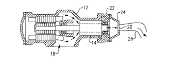
図面を参照すると、図1には、スクリュー圧縮機の概略的な断面図が示されている。スクリュー圧縮機は、ハウジング12、噛み合うロータ14、および冷媒の吸入口18と吐出口20とを有し、吐出口20は、吐出プレート22と吐出管26に連結された吐出ハウジング24とを含む。作動時には、一方のロータ14が駆動ロータであると仮定すると、ロータ14は、他方のロータと係合して回転してこのロータを回転させる。回転するロータ14の協働により、吸入口18を介してロータ14の溝に冷媒ガスが引き込まれ、これらの溝は、噛み合ってガスの容積を捕捉するとともに圧縮し、圧縮された熱い冷媒ガスを吐出ポート20に送る。
Referring to the drawings, FIG. 1 shows a schematic cross-sectional view of a screw compressor. The screw compressor has a
図2に示すように、本発明の油分離器28は、吐出管26の内部に位置するように設計されている。油分離器28は、油ダム30、逆止弁49、および油戻り部48を含む。圧縮されたガス状の冷媒が吐出口20から吐出管26に放出されると、油分離器28は、冷媒が凝縮器に移動する前にこの冷媒から油を取り除くように機能する。
As shown in FIG. 2, the
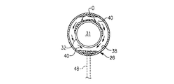
従って、油分離器28は、円状であることが好ましく、入口31を含む中央開口部を有し、この中央開口部は、入口31から出口34に向かって軸方向でかつ径方向に広がるように曲線状に延在する壁32によって形成される。図示のように、油分離器28の水平軸Xは、矢印で示した冷媒Rの流れと同じ方向に延びている。壁32は、油分離器28の面36から吐出管26の内側壁38まで延在しており、油分離器28は、溶接などの周知の方法によって壁38に固定されている。冷媒蒸気が吐出管26を通って流れるのに従って、油Oが吐出管26の壁38に付着するとともに蒸気の流れの方向に流れる。よって、油Oは、壁32,38の間に形成されたダム部40に達するまで壁38に沿って流れるとともに、ダム40によってそれより先に移動することが妨げられる。一方、多くの油が取り除かれた冷媒蒸気は、冷凍サイクルまたは空調サイクルを通って移動し続ける。油分離器28の上端42では、油がダム部40に収集されるとともに、図3の矢印によって示すように重力Gによって壁32の外側面および壁38の内側面に沿って下端44まで下向きに流れる。続いて、油Oは、壁38の下端46に沿って、壁32,38の間に形成された下方ダム部41まで流れるとともに、(図3に点線で示す)油戻り部48の近傍の下方ダム部41に溜まる。油戻り部48は、垂直方向下向きに延びており、油分離器28のダム40から流れてくる余分な油を重力Gを利用して移動させる。油Oは、戻り部48を通って油だめに回収され、スクリューベアリングおよびロータの潤滑に再利用される。重力Gとともにまたは重力Gとは別に、油分離器28と油だめとの圧力差を任意に利用して戻り部48を通って油Oを送ることもできる。図2に示すように、油分離器28は、選択的に逆止弁49を含むことができ、この逆止弁49は、装置の停止時に冷媒が圧縮機に逆流するのを防ぐように、出口34の上部にヒンジ付けされている。
Accordingly, the
壁32は、この壁32の外側にわたって油の流れをさらに保持するために、図4に示すリップ部50を任意に含むことができる。また、ダム40が全体的に垂直な向きを有することは必要条件ではない。重力の作用によって戻り管路への下向きの流れを達成するために、油分離器の向きに垂直な成分が含まれる必要があるが、油分離器の向きが傾斜していれば、装置および吐出管設計に必要な構成は得られる。
The
本発明の好適実施例を開示および説明したが、当業者には他の変更も明らかであろう。従って、本発明の範囲は、請求項の範囲のみによって限定されるものである。 While a preferred embodiment of the invention has been disclosed and described, other modifications will be apparent to those skilled in the art. Therefore, the scope of the present invention is limited only by the appended claims.
26…吐出管
28…油分離器
31…入口
32…壁
34…出口
36…油分離器の面
38…吐出管の壁
40…ダム部
41…下方ダム部
42…油分離器の上端
44…油分離器の下端
46…壁の下端
49…逆止弁
G…重力
O…油
R…冷媒流れ
X…水平軸
26 ...
Claims (14)
内側面を有する吐出管と、
前記吐出管内で入口および該入口よりも直径が大きい出口を構成する前記吐出管の内部の構造体と、
油が前記出口から流出するのを防止する流出防止手段と、前記吐出管の外に油を導く手段と、を有することを特徴とする油分離器。 An oil separator used to separate oil from refrigerant in a compressor,
A discharge pipe having an inner surface,
An internal structure of the discharge pipe constituting an inlet and an outlet having a diameter larger than the inlet in the discharge pipe;
An oil separator comprising: an outflow preventing unit that prevents oil from flowing out of the outlet; and a unit that guides oil out of the discharge pipe.
14. The oil separator according to claim 13, wherein said prevention means includes a lip extending from said wall.
Applications Claiming Priority (1)
| Application Number | Priority Date | Filing Date | Title |
|---|---|---|---|
| US10/319,965 US6953490B2 (en) | 2002-12-16 | 2002-12-16 | In-line oil separator |
Publications (2)
| Publication Number | Publication Date |
|---|---|
| JP2004198101A true JP2004198101A (en) | 2004-07-15 |
| JP4056969B2 JP4056969B2 (en) | 2008-03-05 |
Family
ID=32392967
Family Applications (1)
| Application Number | Title | Priority Date | Filing Date |
|---|---|---|---|
| JP2003407166A Expired - Fee Related JP4056969B2 (en) | 2002-12-16 | 2003-12-05 | Oil separator |
Country Status (9)
| Country | Link |
|---|---|
| US (1) | US6953490B2 (en) |
| EP (1) | EP1431580B1 (en) |
| JP (1) | JP4056969B2 (en) |
| KR (1) | KR100550490B1 (en) |
| CN (1) | CN100436973C (en) |
| AU (1) | AU2003270965B2 (en) |
| BR (1) | BR0305395A (en) |
| DE (1) | DE60313841T2 (en) |
| TW (1) | TWI235219B (en) |
Cited By (1)
| Publication number | Priority date | Publication date | Assignee | Title |
|---|---|---|---|---|
| JP2016114186A (en) * | 2014-12-16 | 2016-06-23 | 株式会社フクハラ | Annular compression pneumatic circuit |
Families Citing this family (5)
| Publication number | Priority date | Publication date | Assignee | Title |
|---|---|---|---|---|
| US20080101974A1 (en) * | 2006-11-01 | 2008-05-01 | Samsung Electronics Co., Ltd. | Rotary compressor |
| DE102006058839A1 (en) * | 2006-12-13 | 2008-06-19 | Pfeiffer Vacuum Gmbh | Lubricant-sealed rotary vane vacuum pump |
| CN105090041B (en) | 2014-04-29 | 2019-08-06 | 开利公司 | Helical-lobe compressor and water cooler with oil eliminator |
| JP6486217B2 (en) * | 2015-06-23 | 2019-03-20 | 日立ジョンソンコントロールズ空調株式会社 | Compressor and refrigeration cycle apparatus |
| CN216381797U (en) * | 2018-10-12 | 2022-04-26 | 马里奥·多林工作坊股份公司 | Reciprocating compressor structure and refrigeration, regulation or heat pump system |
Family Cites Families (24)
| Publication number | Priority date | Publication date | Assignee | Title |
|---|---|---|---|---|
| US767721A (en) * | 1904-05-18 | 1904-08-16 | Denton K Swartwout | Separating device. |
| US1955465A (en) * | 1931-05-11 | 1934-04-17 | Int Precipitation Co | Apparatus for propelling gas carrying abrasive suspended material |
| US1933588A (en) * | 1931-07-02 | 1933-11-07 | Hawley Charles Gilbert | Centrifugal separator |
| US2209339A (en) * | 1937-07-06 | 1940-07-30 | Int Precipitation Co | Variable flow dust collector |
| GB638315A (en) | 1947-09-12 | 1950-06-07 | Percival John Jarvis | Improvements in or relating to separators for separating liquid particles from air or gas |
| US2806550A (en) * | 1953-12-09 | 1957-09-17 | American Air Filter Co | Dust separators or concentrators of the cyclone type |
| GB772763A (en) * | 1954-11-26 | 1957-04-17 | Davidson & Co Ltd | Improvements in or relating to dust separators and collectors |
| DE1172798B (en) | 1962-02-10 | 1964-06-25 | Graubremse Gmbh | Water and oil separators for systems controlled by compressed air |
| FR1524351A (en) | 1967-03-31 | 1968-05-10 | Langlet Froid S A | Device for separating dispersions transported by a gas flow in variable thermodynamic conditions, in particular at variable flow rate |
| FR1573527A (en) | 1967-07-08 | 1969-07-04 | ||
| GB1260378A (en) * | 1968-11-14 | 1972-01-19 | Ustav Pro Vyzkum Motorovych Vozidel | Fluid sampling apparatus |
| US4057075A (en) * | 1973-08-01 | 1977-11-08 | Bayer Aktiengesellschaft | Separator, especially for chimneys |
| US6010902A (en) * | 1988-04-04 | 2000-01-04 | Bristol-Meyers Squibb Company | Antibody heteroconjugates and bispecific antibodies for use in regulation of lymphocyte activity |
| CA1327948C (en) * | 1988-06-02 | 1994-03-22 | Willem Johannes Christian Prinsloo | Vortex tube separating device |
| JP3323781B2 (en) * | 1996-09-05 | 2002-09-09 | 日揮株式会社 | Gas transfer piping |
| JP4132143B2 (en) * | 1996-09-05 | 2008-08-13 | 日揮株式会社 | Gas transfer piping |
| US5706850A (en) | 1996-11-19 | 1998-01-13 | Carrier Corporation | Oil diffuser |
| BE1010851A3 (en) * | 1997-01-15 | 1999-02-02 | Atlas Copco Airpower Nv | LIQUID INJECTED COMPRESSOR at least two cooperating compressor elements. |
| US5800582A (en) * | 1997-03-10 | 1998-09-01 | United Technologies Corporation | Compact water collector |
| BE1011062A3 (en) | 1997-03-25 | 1999-04-06 | Atlas Copco Airpower Nv | A blow-off COMPRESSOR UNIT AND THUS USED moisture separator. |
| JPH11132145A (en) | 1997-10-24 | 1999-05-18 | Orion Mach Co Ltd | Drain discharge device and drain discharge method |
| JP4047467B2 (en) * | 1998-02-17 | 2008-02-13 | 東洋▲ろ▼機製造株式会社 | Filter device for canister |
| US6524373B2 (en) * | 2000-07-28 | 2003-02-25 | Honeywell International Inc. | Two-stage water extractor |
| US20030033791A1 (en) * | 2001-08-15 | 2003-02-20 | Elliott Michael R. | Cyclonic separator for mist collectors |
-
2002
- 2002-12-16 US US10/319,965 patent/US6953490B2/en not_active Expired - Lifetime
-
2003
- 2003-11-20 TW TW092132577A patent/TWI235219B/en not_active IP Right Cessation
- 2003-11-26 DE DE60313841T patent/DE60313841T2/en not_active Expired - Lifetime
- 2003-11-26 EP EP03257452A patent/EP1431580B1/en not_active Expired - Lifetime
- 2003-11-28 BR BR0305395-4A patent/BR0305395A/en not_active IP Right Cessation
- 2003-12-02 KR KR1020030086815A patent/KR100550490B1/en not_active Expired - Fee Related
- 2003-12-05 JP JP2003407166A patent/JP4056969B2/en not_active Expired - Fee Related
- 2003-12-15 AU AU2003270965A patent/AU2003270965B2/en not_active Ceased
- 2003-12-16 CN CNB2003101206588A patent/CN100436973C/en not_active Expired - Fee Related
Cited By (1)
| Publication number | Priority date | Publication date | Assignee | Title |
|---|---|---|---|---|
| JP2016114186A (en) * | 2014-12-16 | 2016-06-23 | 株式会社フクハラ | Annular compression pneumatic circuit |
Also Published As
| Publication number | Publication date |
|---|---|
| US6953490B2 (en) | 2005-10-11 |
| EP1431580A1 (en) | 2004-06-23 |
| TW200424470A (en) | 2004-11-16 |
| HK1067404A1 (en) | 2005-04-08 |
| KR100550490B1 (en) | 2006-02-09 |
| JP4056969B2 (en) | 2008-03-05 |
| CN1508498A (en) | 2004-06-30 |
| US20040112021A1 (en) | 2004-06-17 |
| BR0305395A (en) | 2004-08-31 |
| DE60313841T2 (en) | 2007-09-06 |
| CN100436973C (en) | 2008-11-26 |
| AU2003270965A1 (en) | 2004-07-01 |
| AU2003270965B2 (en) | 2009-07-16 |
| TWI235219B (en) | 2005-07-01 |
| KR20040053789A (en) | 2004-06-24 |
| DE60313841D1 (en) | 2007-06-28 |
| EP1431580B1 (en) | 2007-05-16 |
Similar Documents
| Publication | Publication Date | Title |
|---|---|---|
| US5214937A (en) | Integral oil separator and muffler | |
| US7819644B2 (en) | Scroll compressor with crankshaft venting | |
| KR100613505B1 (en) | Refrigeration cycle unit | |
| EP1229248B1 (en) | Compressor system | |
| CA3144500A1 (en) | Air/oil separator | |
| JP4056969B2 (en) | Oil separator | |
| JP2003269336A (en) | Compressor and oil separator | |
| WO2003081043A1 (en) | Compressor | |
| JP4106280B2 (en) | Gas-liquid separator for liquid-cooled compressor | |
| JP2004132365A (en) | Oil shield as part of crankcase for scroll compressor | |
| HK1067404B (en) | In line oil separator | |
| JP2022049194A (en) | Oil separation element, oil separator and compression system | |
| JPH07208833A (en) | Oil separator for air conditioner | |
| JP2007187074A (en) | Compressor | |
| JPH0510281A (en) | Hermetic compressor | |
| EP3848653B1 (en) | Vertical oil separator and corresponding method | |
| JP4524202B2 (en) | Open type scroll compressor | |
| KR100300593B1 (en) | Oil Separator of Air Conditioner | |
| CN101988503A (en) | Rotary compressor | |
| CN119533014A (en) | Oil separation device and refrigeration equipment thereof | |
| CN121139333A (en) | A compressor cover assembly, a compressor, and a refrigeration device. | |
| CN117329130A (en) | Compressors and air conditioning units | |
| CN113091356A (en) | Lubricating oil separating device | |
| KR19980043395A (en) | Oil separator of hermetic rotary refrigerant compressor | |
| KR19990036417U (en) | compressor |
Legal Events
| Date | Code | Title | Description |
|---|---|---|---|
| A621 | Written request for application examination |
Free format text: JAPANESE INTERMEDIATE CODE: A621 Effective date: 20050819 |
|
| A131 | Notification of reasons for refusal |
Free format text: JAPANESE INTERMEDIATE CODE: A131 Effective date: 20070619 |
|
| A601 | Written request for extension of time |
Free format text: JAPANESE INTERMEDIATE CODE: A601 Effective date: 20070918 |
|
| A602 | Written permission of extension of time |
Free format text: JAPANESE INTERMEDIATE CODE: A602 Effective date: 20070921 |
|
| A521 | Written amendment |
Free format text: JAPANESE INTERMEDIATE CODE: A523 Effective date: 20071011 |
|
| TRDD | Decision of grant or rejection written | ||
| A01 | Written decision to grant a patent or to grant a registration (utility model) |
Free format text: JAPANESE INTERMEDIATE CODE: A01 Effective date: 20071113 |
|
| A61 | First payment of annual fees (during grant procedure) |
Free format text: JAPANESE INTERMEDIATE CODE: A61 Effective date: 20071212 |
|
| R150 | Certificate of patent or registration of utility model |
Free format text: JAPANESE INTERMEDIATE CODE: R150 |
|
| FPAY | Renewal fee payment (event date is renewal date of database) |
Free format text: PAYMENT UNTIL: 20101221 Year of fee payment: 3 |
|
| FPAY | Renewal fee payment (event date is renewal date of database) |
Free format text: PAYMENT UNTIL: 20101221 Year of fee payment: 3 |
|
| FPAY | Renewal fee payment (event date is renewal date of database) |
Free format text: PAYMENT UNTIL: 20111221 Year of fee payment: 4 |
|
| LAPS | Cancellation because of no payment of annual fees |