JP2004198749A - Thermal fixing device, image forming apparatus, and toner reverse transfer prevention method in thermal fixing device - Google Patents
Thermal fixing device, image forming apparatus, and toner reverse transfer prevention method in thermal fixing device Download PDFInfo
- Publication number
- JP2004198749A JP2004198749A JP2002367458A JP2002367458A JP2004198749A JP 2004198749 A JP2004198749 A JP 2004198749A JP 2002367458 A JP2002367458 A JP 2002367458A JP 2002367458 A JP2002367458 A JP 2002367458A JP 2004198749 A JP2004198749 A JP 2004198749A
- Authority
- JP
- Japan
- Prior art keywords
- fixing device
- toner
- cleaning
- recording medium
- heat fixing
- Prior art date
- Legal status (The legal status is an assumption and is not a legal conclusion. Google has not performed a legal analysis and makes no representation as to the accuracy of the status listed.)
- Pending
Links
Images




Landscapes
- Control Or Security For Electrophotography (AREA)
- Developing Agents For Electrophotography (AREA)
- Fixing For Electrophotography (AREA)
Abstract
【課題】熱定着装置において、定着効率を下げることなくクリーニング部材を有効に冷却して、安定した定着を可能としつつ記録媒体への逆転写を防止する。
【解決手段】熱定着装置22の加熱ローラ(加熱部材)30と加圧ローラ(加圧部材)32間に、シート等の記録媒体を通して搬送しながらその記録媒体上のトナー画像を定着する。そのような熱定着装置において、加熱ローラ30または加圧ローラ32に付着したトナーを除去するクリーニングローラ(クリーニング部材)74を備えるとともに、0.1〜1.0m3/minの風量の外気を取り入れクリーニングローラに吹き付けてそのクリーニングローラを冷却する送風装置80を備える。
【選択図】 図3In a heat fixing device, a cleaning member is effectively cooled without lowering the fixing efficiency, thereby enabling stable fixing and preventing reverse transfer to a recording medium.
A toner image on a recording medium is fixed while being conveyed through a recording medium such as a sheet between a heating roller (heating member) 30 and a pressure roller (pressure member) 32 of a heat fixing device 22. Such a heat fixing device is provided with a cleaning roller (cleaning member) 74 for removing toner attached to the heating roller 30 or the pressure roller 32, and takes in outside air having a flow rate of 0.1 to 1.0 m 3 / min. An air blowing device 80 is provided to blow the cleaning roller to cool the cleaning roller.
[Selection diagram] FIG.
Description
【0001】
【発明の属する技術分野】
この発明は、例えば、複写機、プリンタ、ファクシミリ、またはそれらの複合機などの画像形成装置に関する。そのうち特に、帯電・書込み・現像・転写・クリーニング・除電等を繰り返して像担持体に順次トナー画像を形成し、そのトナー画像を逐次転写して、シート・OHPフィルム等の記録媒体に画像を記録する電子写真式の画像形成装置に関する。および、そのような画像形成装置において、画像転写後の記録媒体を加熱部材と加圧部材間に通して搬送しながらその記録媒体上のトナー画像を定着する熱定着装置に関する。ならびに、そのような熱定着装置において、加圧部材または加熱部材に付着したトナーが再び記録媒体に逆転写することを防止する熱定着装置におけるトナー逆転写防止方法に関する。
【0002】
【従来の技術】
従来、電子写真式の画像形成装置では、内部に熱源を有する加熱ローラ等の加熱部材に加圧ローラ等の加圧部材を押し当て、それらの間に画像転写後の記録媒体を通してその記録媒体を搬送しながら、その記録媒体上のトナー画像を定着する熱定着装置を備えるものが主である。
【0003】
この種の熱定着装置では、記録媒体上のトナーが加熱部材に付着する、いわゆるオフセットと呼ばれる現象を生ずることがある。このようなオフセットを生ずると、オフセットしたトナーが加圧部材にも付着し、それら加熱部材および加圧部材から記録媒体に逆転写して記録媒体を汚すことが知られている。
【0004】
このようなオフセットを防止すべく、従来の熱定着装置では、例えば加熱部材の表面にフッ素コートなどを施していた。しかし、環境条件や記録媒体の種類などによって、オフセットを完全に防止することは難しく、やはり逆転写を生ずる問題があった。
【0005】
そこで、従来の熱定着装置では、加熱部材や加圧部材に接触してクリーニングローラ等のクリーニング部材を設け、加熱部材や加圧部材に付着したトナーを除去するものがある。すなわち、表面離型性を向上した加熱部材や加圧部材に対して無垢の金属材料でつくったクリーニング部材を押し当てることにより、表面離型性の差からトナーを除去するものがあった。
【0006】
ところで、近年、画像形成装置では、エネルギの無駄な消費を防止すべく、待機時には熱源への通電を停止し、画像形成の開始に合わせてはじめて熱源へと通電して加熱部材を定着温度まで昇温するようになってきている。このため、加熱部材は、温度応答性を向上する必要があり、例えば加熱ローラであれば、肉厚を1mm以下にして定着温度までの昇温時間を10秒程度まで短縮している。
【0007】
このような画像形成装置にあっては、加熱部材の熱容量が小さいため、定着時における記録媒体への熱移動、加熱部材に接触する部材への熱移動、加熱部材まわりの風の流れなどの影響を受けやすく、加熱部材の温度分布が幅方向で不均一となりやすい問題があった。そして、加熱部材の全領域にわたり温度分布を均一にすることは、スペース的およびコスト的に不可能であった。
【0008】
加熱部材の温度分布が幅方向で不均一となると、定着性能が不安定となるとともに、オフセットが発生しやすく、また熱劣化により加熱部材の寿命が短くなりやすいなどの問題を生ずる。特に重合法により製造した重合トナーを用いる場合には、クリーニング部材に付着堆積したトナー塊が再溶融して記録媒体に逆転写するという問題があった。これは、粉砕法により製造した粉砕トナーを用いる場合には、貯蔵弾性率が高い溶けにくいトナーがクリーニング部材に付着するが、重合法により製造した重合トナーを用いる場合には、貯蔵弾性率が低い普通のトナーがクリーニング部材に付着するからである。
【0009】
この問題は、通紙可能な最大サイズに比較して、小サイズの記録媒体を通紙する場合に特に顕著に生じた。なぜなら、小サイズの場合は、通紙領域が狭く加熱部材に接する面積が小さいから、その狭い領域でのみ温度が下がり、その部分に対応した温度検知手段が熱源の点灯を指示することから、非通紙領域の温度まで不必要に上昇し、その非通紙領域に対応するクリーニング部材上のトナーが溶融して逆転写するからである。
【0010】
【特許文献1】特開平9-325550号公報
さて、このような逆転写の問題を解決すべく、従来の熱定着装置の中には、例えば特許文献1に記載されるように、加熱ローラの温度分布を幅方向で均一とするため、風を当てて加熱ローラの非通紙領域の温度の上がり過ぎを防止するものがある。
【0011】
【特許文献2】特開2002-123119号公報
また、例えば特許文献2に記載されるように、クリーニングローラに沿って通風孔を設けてクリーニングローラの回転とともに熱定着装置内の空気を循環し、クリーニングローラの温度上昇を防ぐものがある。
【0012】
【発明が解決しようとする課題】
しかしながら、前者は、加熱ローラに直接風を送り込むから、加熱ローラの肉厚が1mm以下で熱容量が小さい場合には、加熱ローラの温度変化が激しく、安定した定着を行うことができない問題があった。
【0013】
他方、後者は、通風孔を通して抜ける熱量よりも、クリーニングローラが加圧ローラから受ける熱量の方がはるかに大きいことから、十分な冷却効果を得ることができない問題があった。
【0014】
そこで、この発明の第1の目的は、上述したような熱定着装置において、定着効率を下げることなくクリーニング部材を有効に冷却して、安定した定着を可能としつつ逆転写を防止することにある。
【0015】
この発明の第2の目的は、加熱部材の熱を奪わないようにしてより一層定着効率を下げることなく、クリーニング部材を有効に冷却して、安定した定着を可能としつつ逆転写を防止することにある。
【0016】
この発明の第3の目的は、加熱部材または加圧部材に対するクリーニング部材の接触部位を常時変化するとともに、加熱部材または加圧部材の回転負荷を小さくすることにある。
【0017】
この発明の第4の目的は、加熱部材または加圧部材に対する逆転写を防止する一方、トナー除去効率を向上することにある。
【0018】
この発明の第5の目的は、熱定着装置の小型化を可能とすることにある。
【0019】
この発明の第6の目的は、加熱部材の温度応答性を向上し、画像形成の開始に合わせて短時間で加熱部材を定着温度に昇温可能とし、省エネルギ化を図ることにある。
【0020】
この発明の第7の目的は、定着温度を下げて省エネルギ化を図ることを可能とすることにある。
【0021】
この発明の第8の目的は、貯蔵弾性率が低く溶融しやすい重合トナーを用いても、有効に逆転写を防止しつつ、環境に対応することにある。
【0022】
この発明の第9の目的は、クリーニング部材を幅方向にムラなく均一に冷却することにある。
【0023】
この発明の第10の目的は、上述した目的を達成した熱定着装置を備える画像形成装置を提供することにある。
【0024】
この発明の第11の目的は、クリーニング部材を冷却不足や過冷却を生ずることなく有効に冷却することにある。
【0025】
この発明の第12の目的は、クリーニング部材をさらに有効に冷却することにある。
【0026】
この発明の第13の目的は、定着効率を下げることなくクリーニング部材を有効に冷却して、安定した定着を可能としつつ逆転写を防止する、熱定着装置におけるトナー逆転写防止方法を提供することにある。
【0027】
この発明の第14の目的は、加熱部材の熱を奪わないようにしてより一層定着効率を下げることなく、クリーニング部材を有効に冷却して、安定した定着を可能としつつ逆転写を防止する、熱定着装置におけるトナー逆転写防止方法を提供することにある。
【0028】
この発明の第15の目的は、クリーニング部材を幅方向にムラなく均一に冷却可能とする、熱定着装置におけるトナー逆転写防止方法を提供することにある。
【0029】
【課題を解決するための手段】
そのため、請求項1に記載の発明は、上述した第1の目的を達成すべく、
加熱部材と加圧部材間に記録媒体を通して搬送しながらその記録媒体上のトナー画像を定着する熱定着装置において、
加熱部材に付着したトナーを除去するクリーニング部材を備えるとともに、0.1〜1.0m3/minの風量の外気を取り入れクリーニング部材に吹き付けてそのクリーニング部材を冷却する送風装置を備える、ことを特徴とする。
【0030】
請求項2に記載の発明は、上述した第2の目的を達成すべく、
加熱部材と加圧部材間に記録媒体を通して搬送しながらその記録媒体上のトナー画像を定着する熱定着装置において、
加圧部材に付着したトナーを除去するクリーニング部材を備えるとともに、0.1〜1.0m3/minの風量の外気を取り入れクリーニング部材に吹き付けてそのクリーニング部材を冷却する送風装置を備える、ことを特徴とする。
【0031】
請求項3に記載の発明は、上述した第3の目的も達成すべく、請求項1または2に記載の熱定着装置において、クリーニング部材としてクリーニングローラを用いる、ことを特徴とする。
【0032】
請求項4に記載の発明は、上述した第4の目的も達成すべく、請求項1ないし3のいずれか1に記載の熱定着装置において、加圧部材または加圧部材に付着したトナーをトナー除去部材を介してクリーニング部材で除去する、ことを特徴とする。
【0033】
請求項5に記載の発明は、上述した第5の目的も達成すべく、請求項1ないし4のいずれか1に記載の熱定着装置において、加熱部材と加圧部材のいずれか一方または双方をローラとする、ことを特徴とする。
【0034】
請求項6に記載の発明は、上述した第6の目的も達成すべく、請求項1ないし4のいずれか1に記載の熱定着装置において、加熱部材として肉厚1mm以下のローラを用いる、ことを特徴とする。
【0035】
請求項7に記載の発明は、上述した第7の目的も達成すべく、請求項1ないし4のいずれか1に記載の熱定着装置において、加熱部材と加圧部材のいずれか一方または双方をベルトとする、ことを特徴とする。
【0036】
請求項8に記載の発明は、上述した第8の目的も達成すべく、請求項請求項1ないし7のいずれか1に記載の熱定着装置において、トナーとして重合法により製造した重合トナーを用いる、ことを特徴とする。
【0037】
請求項9に記載の発明は、上述した第9の目的も達成すべく、請求項1ないし8のいずれか1に記載の熱定着装置において、送風装置で記録媒体搬送方向と直交する方向に送風してクリーニング部材を冷却する、ことを特徴とする。
【0038】
請求項10に記載の発明は、上述した第9の目的も達成すべく、請求項1ないし9のいずれか1に記載の熱定着装置において、送風装置を複数備える、ことを特徴とする。
【0039】
請求項11に記載の発明は、上述した第9の目的も達成すべく、請求項10に記載の熱定着装置において、記録媒体搬送方向と直交する方向に分断して送風装置でそれぞれクリーニング部材に幅方向に分けて送風する、ことを特徴とする。
【0040】
請求項12に記載の発明は、上述した第9の目的も達成すべく、請求項1ないし11のいずれか1に記載の熱定着装置において、送風装置にシロッコファンを用いる、ことを特徴とする。
【0041】
請求項13に記載の発明は、上述した第10の目的を達成すべく、画像形成装置において、請求項1ないし12のいずれか1に記載の熱定着装置を備える、ことを特徴とする。
【0042】
請求項14に記載の発明は、上述した第11の目的も達成すべく、請求項13に記載の画像形成装置において、記録媒体のサイズに応じて送風装置をオンオフする、ことを特徴とする。
【0043】
請求項15に記載の発明は、上述した第11の目的も達成すべく、請求項13に記載の画像形成装置において、熱定着装置に温度検知手段を備え、その温度検知手段の検知温度に基づき送風装置をオンオフする、ことを特徴とする。
【0044】
請求項16に記載の発明は、上述した第11の目的も達成すべく、請求項13に記載の画像形成装置において、通紙モードに応じて送風装置をオンオフする、ことを特徴とする。
【0045】
請求項17に記載の発明は、上述した第12の目的も達成すべく、請求項13に記載の画像形成装置において、記録媒体のサイズ、温度検知手段の検知温度、通紙モードの組み合わせに応じて送風装置をオンオフする、ことを特徴とする。
【0046】
請求項18に記載の発明は、上述した第13の目的を達成すべく、
加熱部材と加圧部材間に記録媒体を通して搬送しながらその記録媒体上のトナー画像を定着するとともに、加熱部材に付着したトナーを除去するクリーニング部材を備える熱定着装置におけるトナー逆転写防止方法において、
熱定着装置に備える送風装置を駆動し、0.1〜1.0m3/minの風量の外気を取り入れ、その外気をクリーニング部材に吹き付けてそのクリーニング部材を冷却する、ことを特徴とする。
【0047】
請求項19に記載の発明は、上述した第14の目的を達成すべく、
加熱部材と加圧部材間に記録媒体を通して搬送しながらその記録媒体上のトナー画像を定着するとともに、加圧部材に付着したトナーを除去するクリーニング部材を備える熱定着装置におけるトナー逆転写防止方法において、
熱定着装置に備える送風装置を駆動し、0.1〜1.0m3/minの風量の外気を取り入れ、その外気をクリーニング部材に吹き付けてそのクリーニング部材を冷却する、ことを特徴とする。
【0048】
請求項20に記載の発明は、上述した第15の目的も達成すべく、請求項18または19に記載の熱定着装置におけるトナー逆転写防止方法において、記録媒体搬送方向と直交する方向に分断して複数備える送風装置でそれぞれクリーニング部材に分けて送風する、ことを特徴とする。
【0049】
【発明の実施の形態】
以下、図面を参照しつつ、この発明の実施の形態につき説明する。図1には、この発明に係る熱定着装置を備える電子写真方式の複写機であって、その内部機構の全体概略構成を示す。
【0050】
図中符号100は、複写機装置本体である。複写機装置本体100は、その上に画像読取装置200を取り付け、シートバンク300上に載置してなる。また、画像読取装置200の上には、背面側を支点に上下に開閉自在に自動原稿搬送装置400を取り付けてなる。
【0051】
複写機装置本体100には、内部に、像担持体としてドラム状の感光体10を設ける。この感光体10のまわりには、図中左側に配置する帯電装置11から、感光体10の回転方向(反時計方向)Aに順に、下側に現像装置12、右側に転写装置13、上側にクリーニング装置14を配置してなる。
【0052】
そのうち、現像装置12では、トナーとして、重合法により製造した重合トナーを用い、その重合トナーを現像ローラを用いて付着して感光体10上の静電潜像を可視像化する。
【0053】
また、転写装置13は、上下のローラ15・16の間に転写ベルト17を掛け回して構成し、その転写ベルト17を転写位置Bで感光体10の周面に押し当ててなる。
【0054】
図1中帯電装置11およびクリーニング装置14の左側に設けるものは、現像装置12に新しいトナーを補給するトナー補給装置20である。
【0055】
また、複写機装置本体100の内部には、シートバンク300の後述するシートカセット61から送り出したシートSを転写位置Bを経てスタック位置まで下方から上方へと搬送するシート搬送装置Cを備える。シート搬送装置Cは、供給路R1、手差し供給路R2、およびシート搬送路Rを有してなる。
【0056】
そして、そのシート搬送路Rには、感光体10の上流位置にレジストローラ21を設ける。また、感光体10の下流位置には、熱定着装置22を設ける。詳しくは後述する熱定着装置22には、加熱ローラ(加熱部材)30と加圧ローラ(加圧部材)32を設ける。
【0057】
そのような熱定着装置22のさらに下流には、排出分岐爪34、排出ローラ35・第1加圧ローラ36・第2加圧ローラ37・腰付ローラ38を設ける。そして、その先に、画像形成済みのシートをスタックする排出スタック部(排出位置)39を設けてなる。
【0058】
複写機装置本体100には、図中右側面に、スイッチバック装置42を設けてなる。そのスイッチバック装置42は、シート搬送路Rの排出分岐爪34位置から分岐し、一対のスイッチバックローラ43を備えるスイッチバック位置44まで導く反転路R3と、スイッチバック位置44から、再びシート搬送路Rのレジストローラ21まで導く再搬送路R4とを有するシート搬送装置Dを備える。そのシート搬送装置Dには、シートを搬送する複数のシート搬送ローラ66を備えてなる。
【0059】
現像装置12の図中左側には、レーザ書込装置47を備える。レーザ書込装置47には、不図示のレーザ光源、走査用の回転多面鏡48、ポリゴンモータ49、fθレンズ等の走査光学系50などを設けてなる。
【0060】
画像読取装置200には、光源53、複数のミラー54、結像用光学レンズ55、CCD等のイメージセンサ56などを設ける。そして、上面にはコンタクトガラス57を備えてなる。
【0061】
そのコンタクトガラス57の上の自動原稿搬送装置400には、原稿の載置位置に不図示の原稿セット台を設けるとともに、排出位置に不図示の原稿スタック台を設ける。また、原稿シートを、原稿セット台から画像読取装置200のコンタクトガラス57上の読取位置を経て原稿スタック台まで搬送する不図示の原稿搬送路を有するシート搬送装置を備える。そのシート搬送装置には、原稿シートを搬送する不図示のシート搬送ローラを複数備えてなる。
【0062】
シートバンク300には、内部に、記録媒体であるシート・OHPフィルム等のシートSを収納するシートカセット61を多段に備える。各シートカセット61には、それぞれ対応して呼出ローラ62・供給ローラ63・分離ローラ64を設ける。多段に備えるシートカセット61の図中右側に、装置本体100のシート搬送路Rへと通じる上述した供給路R1を形成する。供給路R1にも、シートを搬送するいくつかのシート搬送ローラ66(シート搬送回転体)を備える。
【0063】
なお、複写機装置本体100には、図中右側面に、手差し供給部68を設ける。その手差し供給部68に、手差しトレイ67を開閉自在に設けるとともに、その手差しトレイ67上にセットした手差しシートを、シート搬送路Rへと導く上述した手差し供給路R2を備える。その手差しトレイ67にも同様に、呼出ローラ62・供給ローラ63・分離ローラ64を設ける。
【0064】
さて、いまこの複写機を用いてコピーをとるときは、不図示のメインスイッチをオンするとともに、自動原稿搬送装置400の原稿セット台に原稿をセットする。ブック原稿のような場合には、自動原稿搬送装置400を開いて画像読取装置200のコンタクトガラス57上に直接原稿をセットし、自動原稿搬送装置400を閉じてそれで押える。
【0065】
そして、不図示のスタートスイッチを押すと、自動原稿搬送装置400に原稿をセットしたときは、原稿をシート搬送ローラにより原稿搬送路を通して、コンタクトガラス57上へと移動してから画像読取装置200を駆動し、原稿内容を読み取って原稿スタック台上に排出する。一方、コンタクトガラス57上に直接原稿をセットしたときは、直ちに画像読取装置200を駆動する。
【0066】
画像読取装置200を駆動すると、画像読取装置200は、光源53をコンタクトガラス57に沿って移動するとともに、光源53からの光をコンタクトガラス57上の原稿面で反射し、その反射光を複数のミラー54で反射し、結像用光学レンズ55を経て、イメージセンサ56に入れ、そのイメージセンサ56で原稿内容を読み取る。
【0067】
また、このとき同時に、不図示の感光体駆動モータで感光体10を回転し、まず図示例では帯電ローラを用いた帯電装置11で表面を一様に帯電し、次いで上述の画像読取装置200で読み取った原稿内容に応じてレーザ光を照射してレーザ書込装置47で書込みを行い、感光体10の表面に静電潜像を形成し、そののち現像装置12でトナーを付着してその静電潜像を可視像化する。
【0068】
また、スタートスイッチを押したとき同時に、シートバンク300中に多段に備える複数のシートカセット61中の選択サイズに対応するシートカセット61内から呼出ローラ62によりシートSを送り出し、続く供給ローラ63・分離ローラ64で1枚ずつ分離して搬送しながら供給路R1に入れ、シート搬送ローラ66で搬送してシート搬送路Rへと導き、レジストローラ21に突き当てて止める。そして、上述した感光体10の可視像化したトナー画像の回転にタイミングを合わせてレジストローラ21を回転し、感光体10の右側へと送り込む。
【0069】
または、手差し給紙部68の手差しトレイ67を開けて、その手差しトレイ67上にセットした手差しシートを呼出ローラ62により送り出し、続く供給ローラ63・分離ローラ64で1枚ずつ分離して搬送しながら手差し供給路R2に入れ、シート搬送ローラ66で搬送してシート搬送路Rへと導き、同じくレジストローラ21で感光体10の回転にタイミングを合わせて該感光体10の右側へと送り込む。
【0070】
それから、感光体10の右側へと送り込んだシートSに、図示例では転写装置13により転写位置Bで感光体10上のトナー画像を転写して画像を形成する。画像転写後の感光体10上の残留トナーはクリーニング装置14で除去して清掃し、不図示の除電装置で感光体10上の残留電位を除去して帯電装置11からはじまる次の画像形成に備える。
【0071】
一方、画像転写後のシートSは、転写ベルト17で搬送して熱定着装置22に入れ、加熱ローラ30と加圧ローラ32間に通して搬送しながら、それらにより熱と圧力を加えてシートS上のトナー画像を定着する。その後、排出ローラ35・第1加圧ローラ36・第2加圧ローラ37・腰付ローラ38により、シートに腰をつけて、排出スタック部39上に排出してそこにスタックする。
【0072】
なお、シートの両面に画像を転写する場合、排出分岐爪34を切り替える。そして、表面にトナー画像を転写したシートを、シート搬送路Rから反転路R3に入れ、シート搬送ローラ66で搬送してスイッチバック位置44へ入れ、スイッチバックローラ43でスイッチバックすることにより再搬送路R4に入れて反転し、シート搬送ローラ66で搬送して再びシート搬送路Rに導き、前述と同様にしてシートの裏面にも画像を転写する。
【0073】
図2には、熱定着装置まわりを拡大して示す。
図中符号70は、熱定着装置22の定着ケースである。定着ケース70は、細長な箱形状で、シート搬送路Rに沿って下面にシート入口71を、上面にシート出口72を設けてなる。
【0074】
そのような定着ケース70内に、図示例では、上述したように加熱部材として加熱ローラ30を、加圧部材として加圧ローラ32をそれぞれ回転自在に設けてなる。
【0075】
加熱ローラ30は、例えば肉厚1mm以下のローラを用いて温度応答性を向上し、定着温度までの昇温時間を10秒程度にまで短縮するようにしてもよい。表面には、フッ素コート処理を施す。そして、内部に熱源23を備える。熱源23は、図示例では、2つであるが、1つでもよいし、3つ以上であってもよい。
【0076】
そのような加熱ローラ30のまわりには、シート分離部材75を設ける。シート分離部材75は、支点を中心として回動自在に支持し、スプリング76で付勢して爪先端を加熱ローラ30の周面に押し当ててなる。そして、加熱ローラ30と加圧ローラ32のニップ位置を通過して加熱ローラ30に密着するシートSを加熱ローラ30から引き剥がし、シート出口72へと導く。
【0077】
また、加熱ローラ30のまわりには、その周面に接触してサーミスタ(温度検知手段)28およびサーモスタット29を設ける。そして、サーミスタ28で加熱ローラ30の温度を検知し、その検知結果に基づき熱源23をオンオフして加熱ローラ30を所定温度に保持する。
【0078】
他方、加圧ローラ32のまわりには、加圧スプリング25で加圧アーム26を支点27を中心として反時計まわりに回動するように付勢する。そして、その加圧アーム26で加圧ローラ32を付勢して加熱ローラ30に押し当て、それらの間にニップを形成してなる。
【0079】
また、加圧ローラ32の周面には、クリーニング部材を接触する。クリーニング部材としては、パットでもブレードでもよく、金属性でもゴム製などでもよいが、図示例では、無垢の金属製のクリーニングローラ74を用いる。そして、このクリーニングローラで加圧ローラ32に付着したトナーを除去する。
【0080】
なお、図2中符号77は、シート搬送路Rに沿って複数備え、シートSの通過を検知するシート検知センサである。
【0081】
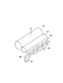
図3には、その熱定着装置22におけるトナー逆転写防止構造を示す。
図示トナー逆転写防止構造には、クリーニングローラ74とともに、送風装置80を設ける。
【0082】
図示例では、送風装置80にシロッコファン81を用いる。そして、そのシロッコファン81を定着ケース70の一端部側に設置し、そのシロッコファン81で0.1〜1.0m3/minの風量の外気を取り入れ、その外気をダクト82で案内してシート搬送方向(記録媒体搬送方向)Gと直交する方向Hに送風し、クリーニングローラ74に吹き付けてそれを冷却する。
【0083】
これにより、加熱ローラ30の熱が加圧ローラ32を介してクリーニングローラ74に伝わることがあったとしても、送風装置80によりクリーニングローラ74を冷却するので、クリーニングローラ74上のトナーが溶融することを防ぎ、トナーが溶融して加圧ローラ32に逆転写し、シートをトナーで汚すことを防止することができる。
【0084】
定着を行うため、加熱ローラ30は、150℃位まで暖める。すると、加圧ローラ32は130℃位まで上昇し、クリーニングローラ74は120℃ほどとなる。クリーニングローラ74が100℃を越えると、逆転写を生ずるおそれがある。そこで、送風装置80でクリーニングローラ74を冷却することにより、クリーニングローラ74を90℃位にまで下げる。
【0085】
重合法により製造した重合トナーは、同一樹脂で粉砕法により製造したトナーに比べ、トナー粒子ごとの構成物質が均一に分散されていて粒子サイズ、形状が一定であるために、後述するクリーニング部材に付着したトナーの貯蔵弾性率が低くなり、クリーニング部材から付着トナーが溶け出す温度も低くなる。しかし、このような重合トナーを用いる場合においても、逆転写を有効に防止することができる。
【0086】
送風装置80で外気を吹き付けてクリーニングローラ74を冷却するので、定着に用いる加熱ローラ30や加圧ローラ32に直接外気を当ててそれらの熱を奪うことなく、定着効率を下げることがない。特に、加熱ローラ30ではなく加圧ローラ32に付着したトナーを除去するクリーニングローラ74を冷却するので、一層加熱ローラ30の熱を奪うことなく、定着効率を下げるおそれをなくすことができる。
【0087】
また、0.1〜1.0m3/minの風量の外気を取り入れクリーニングローラ74に吹き付けて冷却するので、0.1m3/min未満の風量で冷却不足となったり、1.0m3/minを越える風量で冷却し過ぎたりすることなく、クリーニングローラ74を有効に冷却することができる。そして、加圧ローラ32に付着したトナーを除去するクリーニングローラ74を備えるので、安定した定着を可能としつつ逆転写を防止することができる。
【0088】
図4には、トナー逆転写防止構造の他例を示す。
この例では、クリーニング部材であるクリーニングローラ74で、加圧ローラ32ではなく、加熱ローラ30に付着したトナーを除去する。そして、シロッコファン81で0.1〜1.0m3/minの風量の外気を取り入れ、その外気をダクト82で案内してシート搬送方向(記録媒体搬送方向)Gと直交する方向Hに送風し、該クリーニングローラ74に吹き付けてそれを冷却する。
【0089】
このようにすると、クリーニングローラ74を冷却する送風装置80の風が多少加熱ローラ30に当たって加熱ローラ30の熱を奪い、定着効率を下げるおそれはあるが、同様な効果を達成することができる。
【0090】
図5には、トナー逆転写防止構造のさらにまた他例を示す。
クリーニングローラ74は、加熱ローラ30または加圧ローラ32に直接押し当ててそれらに付着したトナーを除去する場合に限らず、この図5に示すように加圧ローラ32に押し当てるトナー除去部材84を介して加圧ローラ32に付着したトナーを除去するものであってもよいし、図示省略するが、加熱ローラ30に押し当てるトナー除去部材84を介して加熱ローラ32に付着したトナーを除去するものであってもよい。
【0091】
図6には、熱定着装置の他例の概略構成を示す。
上述した例では、いずれも加熱部材および加圧部材の双方をローラとしたが、そのいずれか一方または双方をベルトとしてもよい。例えば図6に示すように、加熱部材を加熱ローラ30とし、加圧部材を2つのローラ85に掛け回す加圧ベルト86とする。
【0092】
そして、図示例では、その加圧ベルト86に付着したトナーを除去するクリーニングローラ74を備えるとともに、図示省略するが、0.1〜1.0m3/minの風量の外気を取り入れクリーニングローラ74に吹き付けてそのクリーニングローラ74を冷却する送風装置80を備える。
【0093】
図7には、またトナー逆転写防止構造のさらに他例を示す。
送風装置80は、複数備え、それぞれ記録媒体搬送方向と直交する方向Hに分断してクリーニングローラ74に幅方向に分けて送風するようにしてもよい。
【0094】
例えば図7に示すように、送風装置80を2つ備え、一方のファン81でクリーニングローラ74の一端側半分を冷却し、他方のファン81でダクト82で案内して複数の送風口87から送風してクリーニングローラ74の他端側半分を冷却するようにする。
【0095】
このようにすると、複数の送風装置80を用いてそれぞれクリーニングローラ74に幅方向に分けて万遍なく均一に冷却することができる。
【0096】
図8には、トナーの逆転写を防止する制御フローチャートを示す。
図8に示す制御では、まずS1でシートSがあらかじめ定めたサイズ未満であるか否かを判定し、そのサイズ未満であるときはS2で送風装置80のファン81をオンする。次いで、ステップS3通紙が継続中であるか否かを判定し、通紙が終了したときは、S4でファン81をオフして待機状態とする。
【0097】
このようにシートサイズに応じて送風装置80をオンオフするから、クリーニングローラ74を冷却不足や過冷却を生ずることなく有効に冷却することができる。
【0098】
図9には、トナーの逆転写を防止する他例の制御フローチャートを示す。
図9に示す制御では、まずS11で定着温度があらかじめ定めた温度以上であるか否かを判定し、その温度以上であるときはS12で送風装置80のファン81をオンする。次いで、ステップS13通紙が継続中であるか否かを判定し、通紙が終了したときは、S14でファン81をオフして待機状態とする。
【0099】
このようにサーミスタ28などの温度検知手段の検知温度に基づき送風装置80をオンオフするから、クリーニングローラ74を冷却不足や過冷却を生ずることなく有効に冷却することができる。
【0100】
図10には、トナーの逆転写を防止するさらに他例の制御フローチャートを示す。
【0101】
図10に示す制御では、まずS21で厚紙モードであるか否かを判定し、厚紙モードであるときはS22で送風装置80のファン81をオンする。次いで、ステップS23通紙が継続中であるか否かを判定し、通紙が終了したときは、S24でファン81をオフして待機状態とする。
【0102】
このように通紙モードがあらかじめ定めた厚紙モード等の通紙モードであるか否かに応じて送風装置80をオンオフするから、クリーニングローラ74を冷却不足や過冷却を生ずることなく有効に冷却することができる。
【0103】
図11には、トナーの逆転写を防止するまたさらに他例の制御フローチャートを示す。
【0104】
図11に示す制御では、S31でシートSがあらかじめ定めたサイズ未満であるか否かを判定し、S32で定着温度があらかじめ定めた温度以上であるか否かを判定し、S33で厚紙モードであるか否かを判定し、それらがすべてイエスであるとき、S34で送風装置80のファン81をオンする。次いで、ステップS35で通紙が継続中であるか否かを判定し、通紙が終了したときは、S36でファン81をオフして待機状態とする。
【0105】
このように記録媒体のサイズ、温度検知手段の検知温度、通紙モードの組み合わせに応じて送風装置80をオンオフすると、クリーニング部材をさらに有効に冷却することができる。
【0106】
【発明の効果】
以上説明したとおり、請求項1に記載の発明によれば、送風装置で外気を吹き付けてクリーニング部材を冷却するので、定着に用いる加熱部材や加圧部材に直接外気を当ててそれらの熱を奪うことなく、定着効率を下げることがない。
【0107】
また、0.1〜1.0m3/minの風量の外気を取り入れクリーニング部材に吹き付けて冷却するので、冷却不足となったり冷却し過ぎたりすることなく、クリーニング部材を有効に冷却することができる。そして、加熱部材に付着したトナーを除去するクリーニング部材を備えるので、安定した定着を可能としつつ逆転写を防止することができる。
【0108】
請求項2に係る発明によれば、同様に、送風装置で外気を吹き付けてクリーニング部材を冷却するので、定着に用いる加熱部材や加圧部材に直接外気を当ててそれらの熱を奪うことなく、定着効率を下げることがない。特に、この請求項2に係る発明によれば、加熱部材ではなく加圧部材に付着したトナーを除去するクリーニング部材を冷却するので、一層加熱部材の熱を奪うおそれがなく、定着効率を下げるおそれがない。
【0109】
また、0.1〜1.0m3/minの風量の外気を取り入れクリーニング部材に吹き付けて冷却するので、冷却不足となったり冷却し過ぎたりすることなく、クリーニング部材を有効に冷却することができる。そして、加圧部材に付着したトナーを除去するクリーニング部材を備えるので、安定した定着を可能としつつ逆転写を防止することができる。
【0110】
請求項3に係る発明によれば、クリーニング部材としてクリーニングローラを用いるので、加熱部材または加圧部材に対するクリーニング部材の接触部位を常時変化して加熱部材または加圧部材上にトナーが堆積することを防止することができる。また、クリーニング部材を従動回転して、加熱部材または加圧部材の回転負荷を小さくすることができる。
【0111】
請求項4に係る発明によれば、加圧部材または加圧部材に付着したトナーをトナー除去部材を介してクリーニング部材で除去するので、クリーニング部材上のトナーを戻りにくくして加熱部材または加圧部材に対する逆転写を防止する一方、トナー保持容量を高めてトナー除去効率を向上することができる。
【0112】
請求項5に係る発明によれば、加熱部材と加圧部材のいずれか一方または双方をローラとするので、熱定着装置の小型化を可能とすることができる。
【0113】
請求項6に係る発明によれば、加熱部材として肉厚1mm以下のローラを用いるので、加熱部材の温度応答性を向上し、画像形成の開始に合わせて短時間で加熱部材を定着温度に昇温可能とし、ゼロ・エネルギ待機モード(Zero Energy Standby Mode−ZESM)に対応してスタンバイ時には熱源への通電をカットし、省エネルギ化を図ることができる。
【0114】
請求項7に係る発明によれば、加熱部材と加圧部材のいずれか一方または双方をベルトとするので、定着ニップを大きくすることにより定着温度を下げて省エネルギ化を図ることを可能とすることができる。
【0115】
請求項8に係る発明によれば、トナーとして、今後主流となるであろう重合法により製造した重合トナーを用いるので、貯蔵弾性率が低く溶融しやすい重合トナーを用いても、有効に逆転写を防止しつつ、環境に対応することができる。
【0116】
請求項9に係る発明によれば、送風装置で記録媒体搬送方向と直交する方向に送風してクリーニング部材を冷却するので、クリーニング部材を幅方向にムラなく均一に冷却することができる。
【0117】
請求項10に係る発明によれば、送風装置を複数備えるので、複数の送風装置を用いてクリーニング部材を幅方向にムラなく均一に冷却することができる。
【0118】
請求項11に係る発明によれば、記録媒体搬送方向と直交する方向に分断して送風装置でそれぞれクリーニング部材に幅方向に分けて送風するので、複数の送風装置を用いてそれぞれクリーニング部材に幅方向に分けて万遍なく均一に冷却することができる。
【0119】
請求項12に係る発明によれば、送風装置にシロッコファンを用いるので、同様にクリーニング部材を幅方向にムラなく均一に冷却することができる。
【0120】
請求項13に係る発明によれば、画像形成装置に、請求項1ないし12のいずれか1に記載の熱定着装置を備えるので、上記効果を有する熱定着装置を備えた画像形成装置を提供することができる。
【0121】
請求項14に係る発明によれば、記録媒体のサイズに応じて送風装置をオンオフするので、クリーニング部材を冷却不足や過冷却を生ずることなく有効に冷却することができる。
【0122】
請求項15に係る発明によれば、熱定着装置に温度検知手段を備え、その温度検知手段の検知温度に基づき送風装置をオンオフするので、同様にクリーニング部材を冷却不足や過冷却を生ずることなく有効に冷却することができる。
【0123】
請求項16に係る発明によれば、通紙モードに応じて送風装置をオンオフするので、同様にクリーニング部材を冷却不足や過冷却を生ずることなく有効に冷却することができる。
【0124】
請求項17に係る発明によれば、記録媒体のサイズ、温度検知手段の検知温度、通紙モードの組み合わせに応じて送風装置をオンオフするので、クリーニング部材をさらに有効に冷却することができる。
【0125】
請求項18に係る発明によれば、熱定着装置に備える送風装置を駆動し、0.1〜1.0m3/minの風量の外気を取り入れ、その外気をクリーニング部材に吹き付けてそのクリーニング部材を冷却するので、定着効率を下げることなくクリーニング部材を有効に冷却して、安定した定着を可能としつつ逆転写を防止する、熱定着装置におけるトナー逆転写防止方法を提供することができる。
【0126】
請求項19に係る発明によれば、熱定着装置に備える送風装置を駆動し、0.1〜1.0m3/minの風量の外気を取り入れ、その外気をクリーニング部材に吹き付けてそのクリーニング部材を冷却するので、加熱部材の熱を奪わないようにしてより一層定着効率を下げることなく、クリーニング部材を有効に冷却して、安定した定着を可能としつつ逆転写を防止する、熱定着装置におけるトナー逆転写防止方法を提供することができる。
【0127】
請求項20に係る発明によれば、請求項18または19に記載の熱定着装置におけるトナー逆転写防止方法において、記録媒体搬送方向と直交する方向に分断して複数備える送風装置でそれぞれクリーニング部材に分けて送風するので、クリーニング部材を幅方向にムラなく均一に冷却可能とする、熱定着装置におけるトナー逆転写防止方法を提供することができる。
【図面の簡単な説明】
【図1】この発明による熱定着装置を備える画像形成装置の全体概略構成図である。
【図2】その画像形成装置に備える熱定着装置まわりの拡大概略構成図である。
【図3】その熱定着装置におけるトナー逆転写防止構造を示す斜視図である。
【図4】そのトナー逆転写防止構造の他例を示す斜視図である。
【図5】さらにまた他例を示す斜視図である。
【図6】熱定着装置の他例の概略構成図である。
【図7】またトナー逆転写防止構造のさらに他例を示す斜視図である。
【図8】トナーの逆転写を防止する制御フローチャートである。
【図9】トナーの逆転写を防止する他例の制御フローチャートである。
【図10】トナーの逆転写を防止するさらに他例の制御フローチャートである。
【図11】トナーの逆転写を防止するまたさらに他例の制御フローチャートである。
【符号の説明】
22 熱定着装置
28 サーミスタ(温度検知手段)
30 加熱ローラ(加熱回転部材)
32 加圧ローラ(加圧回転部材)
74 クリーニングローラ(クリーニング部材)
80 送風装置
81 シロッコファン
84 トナー除去部材
86 加圧ベルト(加圧部材)
S シート(記録媒体)
G シート搬送方向(記録媒体搬送方向)
H 記録媒体搬送方向と直交する方向[0001]
TECHNICAL FIELD OF THE INVENTION
The present invention relates to an image forming apparatus such as a copier, a printer, a facsimile, or a multifunction peripheral thereof. Of these, in particular, charging, writing, development, transfer, cleaning, static elimination, etc. are repeated to sequentially form a toner image on the image carrier, and the toner images are sequentially transferred, and the image is recorded on a recording medium such as a sheet or an OHP film. To an electrophotographic image forming apparatus. Also, the present invention relates to a heat fixing device for fixing a toner image on a recording medium while conveying the recording medium after image transfer between a heating member and a pressing member in such an image forming apparatus. In addition, the present invention relates to a method for preventing reverse transfer of toner in a thermal fixing device that prevents toner attached to a pressing member or a heating member from being reversely transferred to a recording medium again in such a thermal fixing device.
[0002]
[Prior art]
Conventionally, in an electrophotographic image forming apparatus, a pressing member such as a pressing roller is pressed against a heating member such as a heating roller having a heat source therein, and the recording medium after image transfer is passed between them. The main one is provided with a heat fixing device for fixing the toner image on the recording medium while being conveyed.
[0003]
In this type of heat fixing device, a phenomenon called offset, in which toner on a recording medium adheres to a heating member, may occur. It is known that when such an offset occurs, the offset toner adheres to the pressing member and is reversely transferred from the heating member and the pressing member to the recording medium, thereby soiling the recording medium.
[0004]
In order to prevent such an offset, in a conventional heat fixing device, for example, a fluorine coat is applied to a surface of a heating member. However, it is difficult to completely prevent the offset depending on the environmental conditions, the type of the recording medium, and the like, and there is still a problem that reverse transfer occurs.
[0005]
Therefore, in a conventional heat fixing device, there is a device in which a cleaning member such as a cleaning roller is provided in contact with a heating member or a pressing member to remove toner attached to the heating member or the pressing member. That is, there has been a method in which a cleaning member made of a solid metal material is pressed against a heating member or a pressing member having improved surface releasability to remove toner from a difference in surface releasability.
[0006]
By the way, in recent years, in order to prevent wasteful consumption of energy, the image forming apparatus stops energizing the heat source during standby, and energizes the heat source only at the start of image formation to raise the heating member to the fixing temperature. It's getting warmer. For this reason, it is necessary to improve the temperature responsiveness of the heating member. For example, in the case of a heating roller, the thickness of the heating member is set to 1 mm or less, and the time for raising the temperature to the fixing temperature is reduced to about 10 seconds.
[0007]
In such an image forming apparatus, since the heat capacity of the heating member is small, the influence of heat transfer to the recording medium at the time of fixing, heat transfer to the member in contact with the heating member, wind flow around the heating member, and the like. And the temperature distribution of the heating member tends to be non-uniform in the width direction. In addition, it was impossible to make the temperature distribution uniform over the entire area of the heating member in terms of space and cost.
[0008]
If the temperature distribution of the heating member is not uniform in the width direction, fixing performance becomes unstable, offset tends to occur, and the life of the heating member tends to be shortened due to thermal degradation. In particular, when a polymerized toner produced by a polymerization method is used, there is a problem that the toner mass adhered and deposited on the cleaning member is re-melted and reversely transferred to a recording medium. This is because when a pulverized toner manufactured by a pulverization method is used, a hardly soluble toner having a high storage modulus adheres to the cleaning member, but when a polymerized toner manufactured by a polymerization method is used, the storage elastic modulus is low. This is because ordinary toner adheres to the cleaning member.
[0009]
This problem occurs particularly remarkably when a small-sized recording medium is passed as compared with the maximum size that can be passed. This is because, in the case of the small size, since the sheet passing area is narrow and the area in contact with the heating member is small, the temperature drops only in the narrow area, and the temperature detecting means corresponding to the area instructs to turn on the heat source. This is because the temperature unnecessarily rises to the temperature of the sheet passing area, and the toner on the cleaning member corresponding to the non-sheet passing area is melted and reversely transferred.
[0010]
[Patent Document 1] JP-A-9-325550
Now, in order to solve such a problem of reverse transfer, some conventional heat fixing devices include, as described in, for example, Japanese Patent Application Laid-Open Publication No. H11-163873, in order to make the temperature distribution of the heating roller uniform in the width direction. To prevent the temperature of the non-sheet passing area of the heating roller from excessively rising.
[0011]
[Patent Document 2] JP-A-2002-123119
Further, as described in, for example, Japanese Patent Application Laid-Open No. H11-163, there is an apparatus in which a ventilation hole is provided along a cleaning roller to circulate the air in the heat fixing device with the rotation of the cleaning roller to prevent the temperature of the cleaning roller from rising.
[0012]
[Problems to be solved by the invention]
However, in the former case, since the wind is sent directly to the heating roller, when the thickness of the heating roller is 1 mm or less and the heat capacity is small, there is a problem that the temperature of the heating roller greatly changes and stable fixing cannot be performed. .
[0013]
On the other hand, the latter has a problem that a sufficient cooling effect cannot be obtained because the amount of heat received by the cleaning roller from the pressure roller is much larger than the amount of heat released through the ventilation holes.
[0014]
Therefore, a first object of the present invention is to effectively cool the cleaning member without lowering the fixing efficiency and prevent reverse transfer while enabling stable fixing in the above-described heat fixing device. .
[0015]
A second object of the present invention is to effectively cool the cleaning member and prevent reverse transfer while enabling stable fixing without further lowering the fixing efficiency by preventing heat from the heating member. It is in.
[0016]
A third object of the present invention is to constantly change the contact portion of the cleaning member with the heating member or the pressing member, and to reduce the rotational load of the heating member or the pressing member.
[0017]
A fourth object of the present invention is to prevent reverse transfer to a heating member or a pressure member and to improve toner removal efficiency.
[0018]
A fifth object of the present invention is to make the heat fixing device compact.
[0019]
A sixth object of the present invention is to improve the temperature responsiveness of the heating member, enable the heating member to be heated to the fixing temperature in a short time in accordance with the start of image formation, and achieve energy saving.
[0020]
A seventh object of the present invention is to enable energy saving by lowering the fixing temperature.
[0021]
An eighth object of the present invention is to cope with the environment while effectively preventing reverse transfer even when a polymer toner having a low storage modulus and easy to melt is used.
[0022]
A ninth object of the present invention is to cool the cleaning member uniformly in the width direction without unevenness.
[0023]
A tenth object of the present invention is to provide an image forming apparatus provided with a heat fixing device that achieves the above object.
[0024]
An eleventh object of the present invention is to effectively cool a cleaning member without causing insufficient cooling or excessive cooling.
[0025]
A twelfth object of the present invention is to cool the cleaning member more effectively.
[0026]
A thirteenth object of the present invention is to provide a method for preventing reverse transfer of a toner in a thermal fixing device, which effectively cools a cleaning member without lowering the fixing efficiency to prevent reverse transfer while enabling stable fixing. It is in.
[0027]
A fourteenth object of the present invention is to effectively cool the cleaning member and prevent reverse transfer while enabling stable fixing without lowering the fixing efficiency by preventing heat from the heating member. An object of the present invention is to provide a method for preventing reverse transfer of toner in a heat fixing device.
[0028]
A fifteenth object of the present invention is to provide a method for preventing reverse transfer of toner in a heat fixing device, which makes it possible to cool a cleaning member uniformly in the width direction without unevenness.
[0029]
[Means for Solving the Problems]
Therefore, the invention described in
In a heat fixing device for fixing a toner image on a recording medium while conveying the recording medium between a heating member and a pressing member,
A cleaning member for removing the toner adhered to the heating member is provided. 3 And a blower that cools the cleaning member by taking in outside air having an air flow rate of / min.
[0030]
The second aspect of the present invention is to achieve the second object described above.
In a heat fixing device for fixing a toner image on a recording medium while conveying the recording medium between a heating member and a pressing member,
A cleaning member for removing the toner adhered to the pressing member is provided. 3 And a blower that cools the cleaning member by taking in outside air having an air flow rate of / min.
[0031]
According to a third aspect of the present invention, in order to achieve the third object, in the heat fixing device according to the first or second aspect, a cleaning roller is used as a cleaning member.
[0032]
According to a fourth aspect of the present invention, there is provided a heat fixing device according to any one of the first to third aspects, wherein the pressing member or the toner adhered to the pressing member is formed by the toner. It is characterized in that it is removed by a cleaning member via a removing member.
[0033]
According to a fifth aspect of the present invention, there is provided a heat fixing apparatus according to any one of the first to fourth aspects, wherein at least one of the heating member and the pressing member is provided. A roller.
[0034]
According to a sixth aspect of the present invention, in order to achieve the sixth object, the heat fixing device according to any one of the first to fourth aspects uses a roller having a thickness of 1 mm or less as a heating member. It is characterized by.
[0035]
According to a seventh aspect of the present invention, there is provided a heat fixing apparatus according to any one of the first to fourth aspects, wherein at least one of the heating member and the pressure member is provided. A belt.
[0036]
According to an eighth aspect of the present invention, in order to attain the eighth object, in the heat fixing device according to any one of the first to seventh aspects, a polymerized toner produced by a polymerization method is used as the toner. , Is characterized.
[0037]
According to a ninth aspect of the present invention, there is provided the heat fixing device according to any one of the first to eighth aspects, wherein the ninth object is achieved by blowing air in a direction orthogonal to a recording medium conveying direction by a blowing device. And cooling the cleaning member.
[0038]
According to a tenth aspect of the present invention, in order to achieve the ninth object, the thermal fixing device according to any one of the first to ninth aspects includes a plurality of blowers.
[0039]
According to an eleventh aspect of the present invention, in order to achieve the ninth object, in the heat fixing device according to the tenth aspect, the heat fixing device is divided into a direction orthogonal to a recording medium conveyance direction and each of the cleaning members is blown to a cleaning member. The air is blown separately in the width direction.
[0040]
According to a twelfth aspect of the present invention, in order to achieve the ninth object, in the heat fixing device according to any one of the first to eleventh aspects, a sirocco fan is used as a blower. .
[0041]
According to a thirteenth aspect of the present invention, in order to achieve the tenth object, an image forming apparatus includes the heat fixing device according to any one of the first to twelfth aspects.
[0042]
According to a fourteenth aspect of the present invention, in the image forming apparatus according to the thirteenth aspect, the blower is turned on and off according to the size of the recording medium in order to achieve the eleventh object.
[0043]
According to a fifteenth aspect of the present invention, in the image forming apparatus according to the thirteenth aspect, a temperature detecting unit is provided in the heat fixing device, and based on a temperature detected by the temperature detecting unit. The blower is turned on and off.
[0044]
According to a sixteenth aspect of the present invention, in order to achieve the eleventh object, in the image forming apparatus according to the thirteenth aspect, a blower is turned on and off in accordance with a paper passing mode.
[0045]
According to a seventeenth aspect of the present invention, in the image forming apparatus according to the thirteenth aspect, in accordance with a combination of a recording medium size, a temperature detected by a temperature detecting unit, and a paper passing mode, in order to achieve the twelfth object. To turn on and off the blower.
[0046]
The invention according to claim 18 is to achieve the thirteenth object described above.
A method for preventing reverse toner transfer in a heat fixing device including a cleaning member for fixing a toner image on a recording medium while conveying the recording medium between the heating member and the pressing member while removing the toner attached to the heating member,
Driving the air blower provided in the heat fixing device, 0.1-1.0 m 3 / Min is taken in outside air, and the outside air is blown to the cleaning member to cool the cleaning member.
[0047]
The nineteenth aspect of the present invention is to achieve the fourteenth object described above.
A method for preventing reverse toner transfer in a thermal fixing device including a cleaning member for fixing a toner image on a recording medium while conveying the recording medium between a heating member and a pressing member while removing toner adhered to the pressing member is provided. ,
Driving the air blower provided in the heat fixing device, 0.1-1.0 m 3 / Min is taken in outside air, and the outside air is blown to the cleaning member to cool the cleaning member.
[0048]
According to a twentieth aspect of the present invention, there is provided a method for preventing reverse transfer of toner in a thermal fixing apparatus according to the eighteenth or nineteenth aspect, wherein the fifteenth object is achieved by dividing the thermal fixing device in a direction orthogonal to a recording medium conveyance direction. And a plurality of blowers, each of which is separated into a cleaning member and blown.
[0049]
BEST MODE FOR CARRYING OUT THE INVENTION
Hereinafter, embodiments of the present invention will be described with reference to the drawings. FIG. 1 shows an overall schematic structure of an internal mechanism of an electrophotographic copying machine provided with a heat fixing device according to the present invention.
[0050]
[0051]
A
[0052]
The developing
[0053]
Further, the
[0054]
A
[0055]
Further, inside the copier
[0056]
A
[0057]
Further downstream of the
[0058]
The copier
[0059]
A
[0060]
The
[0061]
In the
[0062]
The
[0063]
The copier
[0064]
When making a copy using this copier, a main switch (not shown) is turned on and a document is set on a document set table of the
[0065]
Then, when a start switch (not shown) is pressed, when a document is set in the
[0066]
When the
[0067]
At the same time, the
[0068]
Further, at the same time when the start switch is pressed, the sheet S is sent out from the
[0069]
Alternatively, by opening the
[0070]
Then, in the illustrated example, the toner image on the
[0071]
On the other hand, the sheet S after the image transfer is conveyed by the transfer belt 17 into the
[0072]
When transferring an image to both sides of a sheet, the
[0073]
FIG. 2 shows an enlarged view around the heat fixing device.
[0074]
In the illustrated example, the
[0075]
The
[0076]
A
[0077]
A thermistor (temperature detecting means) 28 and a
[0078]
On the other hand, around the
[0079]
Further, the cleaning member contacts the peripheral surface of the
[0080]
In FIG. 2,
[0081]
FIG. 3 shows a toner reverse transfer prevention structure in the
In the illustrated toner reverse transfer prevention structure, a
[0082]
In the illustrated example, a
[0083]
Accordingly, even if the heat of the
[0084]
In order to perform fixing, the
[0085]
The polymerized toner manufactured by the polymerization method has a uniform particle size and shape because the constituent substances of each toner particle are uniformly dispersed compared to the toner manufactured by the pulverization method using the same resin. The storage elastic modulus of the attached toner decreases, and the temperature at which the attached toner melts out of the cleaning member also decreases. However, even when such a polymerized toner is used, reverse transfer can be effectively prevented.
[0086]
Since the cleaning
[0087]
In addition, 0.1-1.0m 3 0.1 m / min. 3 /Min./min. 3 The cleaning
[0088]
FIG. 4 shows another example of the toner reverse transfer prevention structure.
In this example, the cleaning
[0089]
In this case, the air from the
[0090]
FIG. 5 shows still another example of the toner reverse transfer prevention structure.
The cleaning
[0091]
FIG. 6 shows a schematic configuration of another example of the heat fixing device.
In the above-described examples, both the heating member and the pressing member are rollers, but one or both of them may be belts. For example, as shown in FIG. 6, the heating member is a
[0092]
In the illustrated example, a cleaning
[0093]
FIG. 7 shows still another example of the toner reverse transfer prevention structure.
A plurality of
[0094]
For example, as shown in FIG. 7, two
[0095]
In this way, the plurality of blowing
[0096]
FIG. 8 is a control flowchart for preventing reverse transfer of toner.
In the control shown in FIG. 8, first, it is determined whether or not the sheet S is smaller than a predetermined size in S1, and if it is smaller than that size, the
[0097]
Since the
[0098]
FIG. 9 shows a control flowchart of another example for preventing reverse transfer of toner.
In the control shown in FIG. 9, first, at S11, it is determined whether or not the fixing temperature is equal to or higher than a predetermined temperature. When it is equal to or higher than the predetermined temperature, the
[0099]
As described above, since the
[0100]
FIG. 10 shows a control flowchart of still another example for preventing reverse transfer of toner.
[0101]
In the control shown in FIG. 10, first, it is determined in S21 whether or not the mode is the thick paper mode. When the mode is the thick paper mode, the
[0102]
As described above, the
[0103]
FIG. 11 shows a control flowchart of still another example for preventing reverse transfer of toner.
[0104]
In the control shown in FIG. 11, it is determined whether or not the sheet S is smaller than a predetermined size in S31, whether or not the fixing temperature is equal to or higher than a predetermined temperature in S32, and in the thick paper mode in S33. It is determined whether or not there is, and if they are all YES, the
[0105]
When the
[0106]
【The invention's effect】
As described above, according to the first aspect of the present invention, since the cleaning member is cooled by blowing the outside air with the blower, the heat is removed by directly applying the outside air to the heating member and the pressing member used for fixing. Without lowering the fixing efficiency.
[0107]
In addition, 0.1-1.0m 3 Since the cleaning member is cooled by taking in the outside air having an air volume of / min, the cleaning member can be effectively cooled without insufficient cooling or excessive cooling. In addition, since a cleaning member for removing the toner attached to the heating member is provided, it is possible to prevent the reverse transfer while enabling stable fixing.
[0108]
According to the second aspect of the present invention, similarly, the outside air is blown by the blower to cool the cleaning member, so that the outside air is not directly applied to the heating member and the pressing member used for fixing to take away the heat thereof. Does not lower fixing efficiency. In particular, according to the second aspect of the present invention, since the cleaning member for removing the toner attached to the pressing member, not the heating member, is cooled, there is no possibility that the heat of the heating member is further removed, and the fixing efficiency may be reduced. There is no.
[0109]
In addition, 0.1-1.0m 3 Since the cleaning member is cooled by taking in the outside air having an air volume of / min, the cleaning member can be effectively cooled without insufficient cooling or excessive cooling. Since a cleaning member for removing the toner attached to the pressure member is provided, the reverse transfer can be prevented while enabling stable fixing.
[0110]
According to the third aspect of the present invention, since the cleaning roller is used as the cleaning member, the contact portion of the cleaning member with the heating member or the pressure member is constantly changed, so that the toner is deposited on the heating member or the pressure member. Can be prevented. Further, the cleaning member can be driven to rotate, so that the rotational load of the heating member or the pressing member can be reduced.
[0111]
According to the fourth aspect of the invention, since the cleaning member removes the toner adhering to the pressing member or the pressing member via the toner removing member, it is difficult to return the toner on the cleaning member to the heating member or the pressing member. While preventing reverse transfer to the member, the toner holding capacity can be increased to improve the toner removal efficiency.
[0112]
According to the fifth aspect of the present invention, since one or both of the heating member and the pressing member are rollers, it is possible to reduce the size of the heat fixing device.
[0113]
According to the invention according to claim 6, since a roller having a thickness of 1 mm or less is used as the heating member, the temperature responsiveness of the heating member is improved, and the heating member is heated to the fixing temperature in a short time in accordance with the start of image formation. Temperature can be set, and the power supply to the heat source can be cut off during standby in response to the Zero Energy Standby Mode (ZESM) to save energy.
[0114]
According to the seventh aspect of the invention, since one or both of the heating member and the pressing member are formed as a belt, it is possible to reduce the fixing temperature by increasing the fixing nip, thereby saving energy. be able to.
[0115]
According to the invention according to claim 8, since a polymerized toner produced by a polymerization method which will become the mainstream in the future is used, even if a polymerized toner having a low storage modulus and easy to melt is used, the reverse transfer can be effectively performed. , And can respond to the environment.
[0116]
According to the ninth aspect of the present invention, the cleaning member is cooled by blowing air in the direction perpendicular to the recording medium conveyance direction by the blowing device, so that the cleaning member can be uniformly cooled in the width direction.
[0117]
According to the tenth aspect of the present invention, since a plurality of air blowers are provided, the cleaning member can be uniformly cooled in the width direction without unevenness using the plurality of air blowers.
[0118]
According to the invention according to
[0119]
According to the twelfth aspect of the present invention, since the sirocco fan is used for the blower, the cleaning member can be similarly uniformly cooled in the width direction without unevenness.
[0120]
According to a thirteenth aspect of the present invention, since the image forming apparatus includes the heat fixing device according to any one of the first to twelfth aspects, an image forming apparatus including the heat fixing device having the above-described effect is provided. be able to.
[0121]
According to the fourteenth aspect, since the blower is turned on and off according to the size of the recording medium, the cleaning member can be effectively cooled without causing insufficient cooling or excessive cooling.
[0122]
According to the invention according to claim 15, the thermal fixing device is provided with a temperature detecting means, and the blower is turned on and off based on the temperature detected by the temperature detecting means. It can be cooled effectively.
[0123]
According to the sixteenth aspect of the present invention, the blower is turned on / off in accordance with the paper passing mode, so that the cleaning member can be effectively cooled without causing insufficient cooling or excessive cooling.
[0124]
According to the seventeenth aspect of the present invention, since the blower is turned on / off in accordance with a combination of the size of the recording medium, the temperature detected by the temperature detecting means, and the paper passing mode, the cleaning member can be cooled more effectively.
[0125]
According to the invention according to claim 18, the blowing device provided in the heat fixing device is driven, and the air blowing device is driven by 0.1 to 1.0 m. 3 / Min air flow is blown into the cleaning member to cool the cleaning member, so the cleaning member can be effectively cooled without lowering the fixing efficiency, and the reverse transfer can be performed while enabling stable fixing. It is possible to provide a method for preventing the reverse transfer of the toner in the heat fixing device, which prevents the reverse transfer.
[0126]
According to the nineteenth aspect of the present invention, the air blower provided in the heat fixing device is driven, and the blower is set to 0.1 to 1.0 m. 3 / Min air is blown into the cleaning member and the cleaning member is cooled by blowing the outside air onto the cleaning member, so that the heat of the heating member is not taken away and the cleaning member is effectively cooled without further lowering the fixing efficiency. As a result, it is possible to provide a method for preventing reverse transfer of toner in a heat fixing device, which enables stable fixing and prevents reverse transfer.
[0127]
According to a twentieth aspect of the present invention, in the method for preventing reverse transfer of toner in the thermal fixing device according to the eighteenth or nineteenth aspect, each of the cleaning members is divided into a plurality of blowers in a direction orthogonal to the recording medium transport direction. Since the air is separately blown, it is possible to provide a method for preventing the toner from being reversely transferred in the heat fixing device, which can uniformly cool the cleaning member in the width direction without unevenness.
[Brief description of the drawings]
FIG. 1 is an overall schematic configuration diagram of an image forming apparatus including a heat fixing device according to the present invention.
FIG. 2 is an enlarged schematic configuration diagram around a heat fixing device provided in the image forming apparatus.
FIG. 3 is a perspective view showing a toner reverse transfer prevention structure in the heat fixing device.
FIG. 4 is a perspective view showing another example of the toner reverse transfer prevention structure.
FIG. 5 is a perspective view showing still another example.
FIG. 6 is a schematic configuration diagram of another example of the heat fixing device.
FIG. 7 is a perspective view showing still another example of the toner reverse transfer prevention structure.
FIG. 8 is a control flowchart for preventing reverse transfer of toner.
FIG. 9 is a control flowchart of another example for preventing reverse transfer of toner.
FIG. 10 is a control flowchart of still another example for preventing reverse transfer of toner.
FIG. 11 is a control flowchart of still another example for preventing reverse transfer of toner.
[Explanation of symbols]
22 Thermal fixing device
28 Thermistor (Temperature detecting means)
30 Heating roller (heating rotating member)
32 pressure roller (pressure rotation member)
74 Cleaning roller (cleaning member)
80 blower
81 Sirocco fan
84 Toner removal member
86 pressure belt (pressure member)
S sheet (recording medium)
G Sheet transport direction (recording medium transport direction)
H Direction perpendicular to the recording medium transport direction
Claims (20)
前記加熱部材に付着したトナーを除去するクリーニング部材を備えるとともに、0.1〜1.0m3/minの風量の外気を取り入れ前記クリーニング部材に吹き付けてそのクリーニング部材を冷却する送風装置を備えることを特徴とする、熱定着装置。In a heat fixing device for fixing a toner image on a recording medium while conveying the recording medium between a heating member and a pressing member,
A cleaning device for removing the toner adhered to the heating member, and a blower for cooling the cleaning member by taking in the outside air having a flow rate of 0.1 to 1.0 m 3 / min and blowing the air on the cleaning member. Characterized by a thermal fixing device.
前記加圧部材に付着したトナーを除去するクリーニング部材を備えるとともに、0.1〜1.0m3/minの風量の外気を取り入れ前記クリーニング部材に吹き付けてそのクリーニング部材を冷却する送風装置を備えることを特徴とする、熱定着装置。In a heat fixing device for fixing a toner image on a recording medium while conveying the recording medium between a heating member and a pressing member,
A cleaning member for removing the toner adhered to the pressure member, and a blower for cooling the cleaning member by taking in outside air having a flow rate of 0.1 to 1.0 m 3 / min and blowing the air on the cleaning member. A heat fixing device.
前記熱定着装置に備える送風装置を駆動し、0.1〜1.0m3/minの風量の外気を取り入れ、その外気をクリーニング部材に吹き付けてそのクリーニング部材を冷却することを特徴とする、熱定着装置におけるトナー逆転写防止方法。In a method for preventing reverse transfer of toner in a thermal fixing device including a cleaning member for fixing a toner image on a recording medium while conveying the recording medium between a heating member and a pressing member while removing the toner attached to the heating member, ,
A blower provided in the heat fixing device is driven to take in outside air having a flow rate of 0.1 to 1.0 m 3 / min, and the outside air is blown to a cleaning member to cool the cleaning member. A method for preventing reverse transfer of toner in a fixing device.
前記熱定着装置に備える送風装置を駆動し、0.1〜1.0m3/minの風量の外気を取り入れ、その外気をクリーニング部材に吹き付けてそのクリーニング部材を冷却することを特徴とする、熱定着装置におけるトナー逆転写防止方法。Method for preventing reverse toner transfer in a thermal fixing device including a cleaning member for fixing a toner image on a recording medium while conveying the recording medium between a heating member and a pressing member and removing toner attached to the pressing member At
A blower provided in the heat fixing device is driven to take in outside air having a flow rate of 0.1 to 1.0 m 3 / min, and the outside air is blown to a cleaning member to cool the cleaning member. A method for preventing reverse transfer of toner in a fixing device.
Priority Applications (1)
| Application Number | Priority Date | Filing Date | Title |
|---|---|---|---|
| JP2002367458A JP2004198749A (en) | 2002-12-19 | 2002-12-19 | Thermal fixing device, image forming apparatus, and toner reverse transfer prevention method in thermal fixing device |
Applications Claiming Priority (1)
| Application Number | Priority Date | Filing Date | Title |
|---|---|---|---|
| JP2002367458A JP2004198749A (en) | 2002-12-19 | 2002-12-19 | Thermal fixing device, image forming apparatus, and toner reverse transfer prevention method in thermal fixing device |
Publications (1)
| Publication Number | Publication Date |
|---|---|
| JP2004198749A true JP2004198749A (en) | 2004-07-15 |
Family
ID=32764332
Family Applications (1)
| Application Number | Title | Priority Date | Filing Date |
|---|---|---|---|
| JP2002367458A Pending JP2004198749A (en) | 2002-12-19 | 2002-12-19 | Thermal fixing device, image forming apparatus, and toner reverse transfer prevention method in thermal fixing device |
Country Status (1)
| Country | Link |
|---|---|
| JP (1) | JP2004198749A (en) |
Cited By (5)
| Publication number | Priority date | Publication date | Assignee | Title |
|---|---|---|---|---|
| JP2006065194A (en) * | 2004-08-30 | 2006-03-09 | Ricoh Co Ltd | Image forming method, toner for the same, process cartridge, and image forming apparatus |
| JP2007079032A (en) * | 2005-09-13 | 2007-03-29 | Canon Inc | Image heating device |
| US7251432B2 (en) * | 2004-08-24 | 2007-07-31 | Sharp Kabushiki Kaisha | System for collecting an unfixed developer with an airflow |
| US7526223B2 (en) * | 2005-05-10 | 2009-04-28 | Ricoh Company, Ltd. | Heat exhausting structure and image forming apparatus |
| CN107132740A (en) * | 2016-02-26 | 2017-09-05 | 富士施乐株式会社 | Fixing device, collecting drum and image forming apparatus |
-
2002
- 2002-12-19 JP JP2002367458A patent/JP2004198749A/en active Pending
Cited By (5)
| Publication number | Priority date | Publication date | Assignee | Title |
|---|---|---|---|---|
| US7251432B2 (en) * | 2004-08-24 | 2007-07-31 | Sharp Kabushiki Kaisha | System for collecting an unfixed developer with an airflow |
| JP2006065194A (en) * | 2004-08-30 | 2006-03-09 | Ricoh Co Ltd | Image forming method, toner for the same, process cartridge, and image forming apparatus |
| US7526223B2 (en) * | 2005-05-10 | 2009-04-28 | Ricoh Company, Ltd. | Heat exhausting structure and image forming apparatus |
| JP2007079032A (en) * | 2005-09-13 | 2007-03-29 | Canon Inc | Image heating device |
| CN107132740A (en) * | 2016-02-26 | 2017-09-05 | 富士施乐株式会社 | Fixing device, collecting drum and image forming apparatus |
Similar Documents
| Publication | Publication Date | Title |
|---|---|---|
| US6934507B2 (en) | Image forming apparatus | |
| US7623822B2 (en) | Image forming apparatus having control of transportation unit fans according to sheet width | |
| US7433623B2 (en) | Image forming apparatus with two recording sheet cooling outlets | |
| JP5353333B2 (en) | Image forming apparatus | |
| JP4109886B2 (en) | Image forming apparatus | |
| JP2003228260A (en) | Cooling device and image forming device | |
| JP2008299291A (en) | Image forming apparatus and program | |
| JP2009244695A (en) | Air flow-generating device, recording material heating/cleaning device, and image forming apparatus | |
| JP2004029471A (en) | Image forming apparatus | |
| JP2004045723A (en) | Image forming apparatus | |
| JP4006258B2 (en) | Image forming apparatus | |
| JP5298591B2 (en) | Image fixing and solidifying device and image forming apparatus | |
| JP2004198749A (en) | Thermal fixing device, image forming apparatus, and toner reverse transfer prevention method in thermal fixing device | |
| JPH0934321A (en) | Image forming device | |
| JP3397603B2 (en) | Image forming device | |
| JP2004271556A (en) | Thermal fixing device and image forming device | |
| JP2004191580A (en) | Thermal fixing device and image forming device | |
| JP2001166622A (en) | Fixing device | |
| JP2003233227A (en) | Image forming device | |
| JP2005070602A (en) | Thermal fixing device and image forming apparatus | |
| JP2004035177A (en) | Image formation device | |
| JP2000250381A (en) | Drive control method of cooling means, storage medium, and image forming apparatus | |
| JP2004361626A (en) | Image forming apparatus | |
| JP3771486B2 (en) | Fixing device and image forming machine provided with the fixing device | |
| JP2005227454A (en) | Image forming apparatus |
Legal Events
| Date | Code | Title | Description |
|---|---|---|---|
| A621 | Written request for application examination |
Free format text: JAPANESE INTERMEDIATE CODE: A621 Effective date: 20050221 |
|
| A977 | Report on retrieval |
Free format text: JAPANESE INTERMEDIATE CODE: A971007 Effective date: 20070309 |
|
| A131 | Notification of reasons for refusal |
Free format text: JAPANESE INTERMEDIATE CODE: A131 Effective date: 20070320 |
|
| A521 | Written amendment |
Free format text: JAPANESE INTERMEDIATE CODE: A523 Effective date: 20070511 |
|
| A02 | Decision of refusal |
Free format text: JAPANESE INTERMEDIATE CODE: A02 Effective date: 20081219 |