JP2004198822A - Driving force transmitting device and image forming apparatus - Google Patents
Driving force transmitting device and image forming apparatus Download PDFInfo
- Publication number
- JP2004198822A JP2004198822A JP2002368540A JP2002368540A JP2004198822A JP 2004198822 A JP2004198822 A JP 2004198822A JP 2002368540 A JP2002368540 A JP 2002368540A JP 2002368540 A JP2002368540 A JP 2002368540A JP 2004198822 A JP2004198822 A JP 2004198822A
- Authority
- JP
- Japan
- Prior art keywords
- driving force
- convex portion
- rotation axis
- driving
- image forming
- Prior art date
- Legal status (The legal status is an assumption and is not a legal conclusion. Google has not performed a legal analysis and makes no representation as to the accuracy of the status listed.)
- Pending
Links
- 230000008878 coupling Effects 0.000 claims abstract description 69
- 238000010168 coupling process Methods 0.000 claims abstract description 69
- 238000005859 coupling reaction Methods 0.000 claims abstract description 69
- 239000002699 waste material Substances 0.000 claims description 60
- 230000005540 biological transmission Effects 0.000 claims description 33
- 238000011144 upstream manufacturing Methods 0.000 claims description 10
- 239000000843 powder Substances 0.000 claims description 9
- 239000000758 substrate Substances 0.000 claims description 7
- 239000000126 substance Substances 0.000 abstract 2
- 238000012546 transfer Methods 0.000 description 49
- 238000011084 recovery Methods 0.000 description 38
- 230000032258 transport Effects 0.000 description 29
- 238000000034 method Methods 0.000 description 22
- 238000010586 diagram Methods 0.000 description 17
- 230000008569 process Effects 0.000 description 17
- 230000002093 peripheral effect Effects 0.000 description 9
- 238000012545 processing Methods 0.000 description 9
- 238000004140 cleaning Methods 0.000 description 8
- 239000000463 material Substances 0.000 description 5
- 230000006870 function Effects 0.000 description 4
- 238000012937 correction Methods 0.000 description 3
- 230000003014 reinforcing effect Effects 0.000 description 3
- 239000003086 colorant Substances 0.000 description 2
- 238000007599 discharging Methods 0.000 description 2
- 239000000428 dust Substances 0.000 description 2
- 230000000694 effects Effects 0.000 description 2
- 238000005516 engineering process Methods 0.000 description 2
- 239000011521 glass Substances 0.000 description 2
- 238000000465 moulding Methods 0.000 description 2
- 239000004033 plastic Substances 0.000 description 2
- 229910000831 Steel Inorganic materials 0.000 description 1
- 238000003705 background correction Methods 0.000 description 1
- 230000015572 biosynthetic process Effects 0.000 description 1
- 239000000969 carrier Substances 0.000 description 1
- 239000003795 chemical substances by application Substances 0.000 description 1
- 238000011109 contamination Methods 0.000 description 1
- 238000007796 conventional method Methods 0.000 description 1
- 238000011161 development Methods 0.000 description 1
- 230000005684 electric field Effects 0.000 description 1
- 238000000605 extraction Methods 0.000 description 1
- 238000003384 imaging method Methods 0.000 description 1
- 230000007774 longterm Effects 0.000 description 1
- 238000012423 maintenance Methods 0.000 description 1
- 230000007246 mechanism Effects 0.000 description 1
- 230000003287 optical effect Effects 0.000 description 1
- 238000003825 pressing Methods 0.000 description 1
- 239000011347 resin Substances 0.000 description 1
- 229920005989 resin Polymers 0.000 description 1
- 238000007789 sealing Methods 0.000 description 1
- 238000010008 shearing Methods 0.000 description 1
- 239000010959 steel Substances 0.000 description 1
- 239000000454 talc Substances 0.000 description 1
- 229910052623 talc Inorganic materials 0.000 description 1
Images

Landscapes
- Dry Development In Electrophotography (AREA)
- Cleaning In Electrography (AREA)
- Electrophotography Configuration And Component (AREA)
Abstract
Description
【0001】
【発明の属する技術分野】
本発明は、例えば複写機、プリンタ、ファクシミリ等の画像形成装置で使用され、回転を必要とする着脱自在なユニットに駆動を伝達する駆動力伝達装置に関する。
【0002】
【従来の技術】
従来の画像形成装置として、静電潜像を現像器で現像することにより得られたトナー像を形成担持する像担持体(例えば感光体ドラム)と、感光体ドラムに対向配置される中間転写体(中間転写ベルト)と、中間転写ベルト上に感光体ドラム上のトナー像を転写する一次転写装置と、記録媒体(例えば用紙)に中間転写ベルト上のトナー像を転写する二次転写装置とを備えたものがある。
このような画像形成装置では、一次転写後の感光体ドラム上にトナーが残留するため、この残留トナーをドラムクリーナで清掃・除去した後に、次のトナー像を形成する。また、二次転写後の中間転写ベルト上にもトナーが残留するため、この残留トナーをベルトクリーナで清掃・除去した後に、次のトナー像を転写する。そして、これらドラムクリーナやベルトクリーナで回収された残留トナー(廃トナー)は、搬送されて回収容器に回収される。
【0003】
特に、カラー画像形成装置では、通常はイエロー(Y)、マゼンタ(M)、シアン(C)、ブラック(K)の画像を形成する4個の感光体ドラムが中間転写ベルトの周囲に配設され、それぞれの感光体ドラムに配設されたドラムクリーナから廃トナーが生じる。これらY、M、C、Kの廃トナーを一括して1個の回収容器に回収するために、Y、M、C、Kのドラムクリーナやベルトクリーナから廃トナーを回収容器へ搬送する廃トナー搬送ユニットを設けている。この廃トナー搬送ユニットはメンテナンスの必要から画像形成装置本体とは着脱自在に構成され、トナー搬送のための搬送部材へは、画像形成装置本体からカップリングにより駆動力が伝達されるように構成されている。
【0004】
また、現像剤としてトナーおよびキャリアを有する二成分現像剤を用いる場合に、現像器にトナーを補給するトナー容器ユニットが画像形成装置本体とは着脱自在に配設されるが、トナー容器ユニットに貯蔵されたトナーを現像器に搬送する搬送部材へは画像形成装置本体からカップリングにより駆動力が伝達されるように構成されている。
【0005】
このような廃トナー搬送ユニットやトナー容器ユニット等の駆動力を伝達する必要があるユニットでは、駆動力の伝達効率を考慮して画像形成装置本体側に設けられた駆動軸と同軸上で連結するために、画像形成装置本体に対して駆動軸と平行な方向で着脱する方式が採用されている。
【0006】
ここで、従来技術として、現像カートリッジが画像形成装置本体に設けられたロータリーユニットに装着された状態で、現像カートリッジの駆動力受け部が画像形成装置本体の駆動伝達部材と同軸上に位置し、駆動伝達部材と駆動力受け部とがカップリング連結する技術が存在する(例えば、特許文献1参照)。また、現像装置のトナー供給ローラと一体に回転するカップリングギヤが装置本体に設けたジョイント駆動軸及びその先端のオルダムジョイントと略同軸上で回転する技術が存在する(例えば、特許文献2参照)。
【0007】
【特許文献1】
特開平9−297443号公報(第17頁、図11)
【特許文献2】
特開2000−227690号公報(第4頁、図3)
【0008】
【発明が解決しようとする課題】
ところで、廃トナー搬送ユニットやトナー容器ユニット等の駆動力を伝達する必要があるユニットについては、画像形成装置の配置構成によっては画像形成装置本体側に設けられた駆動軸と平行な方向での着脱が困難であるために、駆動軸に対して直交する方向から着脱する構成を採用する場合がある。しかしながら、駆動軸に対して直交する方向から移動可能なカップリング構成では、ギヤを組み合わせた方式が用いられるが、かかる方式ではギヤ同士の軸間距離を高精度に設定しなければいわゆる歯飛びが発生し、駆動力を効率よく伝達できないという問題があった。また、駆動軸と平行な方向で着脱する方式を採用した場合には、駆動軸に対して直交する方向からの装着動作の後、駆動軸と平行な方向への装着動作を行う2段階の動作が必要となり、着脱操作が煩雑となるという問題もあった。
【0009】
本発明は、以上の技術的課題を解決するためになされたものであって、その目的とするところは、着脱可能なユニットに駆動力を効率よく伝達することにある。さらに他の目的は、ユニットの装着に際しての着脱操作性を向上することにある。
【0010】
【課題を解決するための手段】
本発明の駆動伝達装置では、回転可能な基体に回転軸とは平行かつ離れて配設された駆動側凸部を有する駆動力伝達部材と、回転可能な基体に回転軸とは離れて配設された受け側凸部を有する駆動力受け部材とによりカップリングを構成し、駆動力受け部材を駆動力伝達部材から回転軸に対し直交する方向に引き抜く際には、受け側凸部が駆動側凸部をすり抜けるようにしてカップリングが解除されるように構成されている。これにより、着脱可能なユニットに駆動力を効率よく伝達することができる。
すなわち、本発明の駆動力伝達装置は、回転可能な基体に回転軸と平行に回転軸とは離れて配設された駆動側凸部を有する駆動力伝達部材と、回転可能な基体に回転軸とは離れて配設された受け側凸部を有する駆動力受け部材とを備え、駆動力受け部材を駆動力伝達部材から回転軸に対し直交する方向に引き抜く際に、受け側凸部が駆動側凸部をすり抜けるように構成されたことを特徴としている。
【0011】
また、本発明の駆動力伝達装置は、回転可能な基体に回転軸と平行に回転軸とは離れて配設されるともに、断面形状が円形または内角が鈍角である多角形で形成された柱状凸部を備えた駆動力伝達部材と、回転可能な基体に回転軸とは離れて配設されるともに、回転方向上流側に法線が回転軸と直交する平面が形成された壁状凸部を備えた駆動力受け部材とから構成されたことを特徴としている。また、駆動力受け部材は、駆動伝達受け部材側から回転可能に構成されたことを特徴とすることができる。また、駆動力伝達部材は、駆動源からウォームギヤを介して回転駆動を受けることを特徴とすることができる。また、駆動力受け部材は、壁状凸部の回転最小半径が駆動力伝達部材の柱状凸部の断面半径よりも大きいことを特徴とすることができる。さらに、駆動力伝達部材は、柱状凸部が1または複数配設されたことを特徴とすることができる。
【0012】
また、本発明の駆動伝達装置は、回転可能な基体に回転軸とは離れて配設されるともに、回転方向上流側に法線が回転軸と直交する平面が形成された壁状凸部を備えた駆動力伝達部材と、回転可能な基体に回転軸と平行に回転軸とは離れて配設されるともに、断面形状が円形または内角が鈍角である多角形で形成された柱状凸部を備えた駆動力受け部材とから構成されたことを特徴としている。また、駆動力伝達部材は、駆動力伝達部材側から回転可能に構成されたことを特徴とすることができる。
【0013】
また、本発明の駆動伝達装置は、回転可能な基体に回転軸と平行に回転軸とは離れて配設されるともに、断面形状が円形または内角が鈍角である多角形で形成された柱状凸部を備えた駆動力伝達部材と、回転可能な基体に回転軸とは離れて配設されるともに、回転方向上流側に法線が回転軸と直交する平面が形成された壁状凸部であって、基体と壁状凸部との接合部が駆動力伝達部材の柱状凸部の回転半径を含んだ外側に配置されたことを特徴としている。
【0014】
また、本発明を画像形成装置として捉え、駆動源と、駆動源により回転可能な基体に回転軸と平行に回転軸とは離れて配設された駆動側凸部を有する駆動力伝達部材とを備え、回転可能な基体に回転軸とは離れて配設された受け側凸部を有する駆動力受け部材が配設されたユニットを、駆動力伝達部材から回転軸に対し直交する方向に引き抜く際に、受け側凸部が駆動側凸部をすり抜けるように構成されたことを特徴としている。
【0015】
さらに、本発明の画像形成装置は、駆動源と、駆動源により回転可能な基体に回転軸と平行に回転軸とは離れて配設されるともに、断面形状が円形または内角が鈍角である多角形で形成された柱状凸部を有する駆動力伝達部材とを備え、回転可能な基体に回転軸とは離れて配設されるともに、回転方向上流側に法線が回転軸と直交する平面が形成された壁状凸部を有する駆動力受け部材が配設され、駆動力受け部材が駆動力伝達部材と結合してカップリングを形成するユニットが着脱自在に構成されたことを特徴としている。特に、ユニットは、廃棄粉体回収装置を備えたことを特徴とすることができる。また、ユニットは、トナー供給装置を備えたことを特徴とすることができる。
【0016】
【発明の実施の形態】
以下、添付図面を参照して、実施の形態について詳細に説明する。
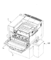
図1は、実施の一形態に係る画像形成装置の全体構成を示した図である。図1に示す画像形成装置は、プリンタ本体1とプリンタ本体1が載置される基台2とを有しており、プリンタ本体1には、プリンタ本体1から排出される廃トナーや廃現像剤(以下、廃棄粉体ともいう)を回収する収容手段としての廃棄粉体回収装置100が外付けされている。なお図1は、プリンタ本体1の前扉1aを開放した状態を示している。
【0017】
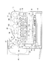
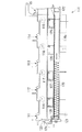
図2は、プリンタ本体1を示した図である。プリンタ本体1は、各色の階調データに対応して画像形成を行う画像プロセス系10、記録用紙(シート)を搬送するシート搬送系40、例えばパーソナルコンピュータや画像読み取り装置等に接続され、受信された画像データに対して所定の画像処理を施す画像処理系であるIPS(Image Processing System)50を備えている。
【0018】
画像プロセス系10は、水平方向に一定の間隔を置いて並列に配置される、イエロー(Y)、マゼンタ(M)、シアン(C)、ブラック(K)の4つの画像形成ユニット11Y,11M,11C,11K、これら画像形成ユニット11Y,11M,11C,11Kの感光体ドラム12に形成された各色のトナー像を中間転写ベルト21上に多重転写させる転写ユニット20、画像形成ユニット11Y,11M,11C,11Kに対してレーザ光を照射する光学系ユニットであるROS(Raster Output System)30を備えている。これら転写ユニット20および中間転写ベルト21によって中間転写手段が構成される。また、プリンタ本体1には、転写ユニット20によって二次転写された記録用紙上のトナー像を、熱および圧力を用いて記録用紙に定着させる定着器29を備えている。さらに、転写ユニット20の上部には、画像形成ユニット11Y,11M,11C,11Kに対して各色のトナーを供給するためのトナーカートリッジ19Y,19M,19C,19Kが設けられている。
【0019】
転写ユニット20は、中間転写体である中間転写ベルト21を駆動するドライブロール22、中間転写ベルト21に一定のテンションを付与するテンションロール23、重畳された各色のトナー像を記録用紙に二次転写するためのバックアップロール24、中間転写ベルト21上に存在する残留トナー等を除去するベルトクリーナ(クリーニング手段)25を備えている。中間転写ベルト21は、このドライブロール22とテンションロール23およびバックアップロール24との間に一定のテンションで掛け渡されており、定速性に優れた専用のモータ(図示せず)によって回転駆動されるドライブロール22により、矢印方向に所定の速度で循環駆動されるようになっている。この中間転写ベルト21は、例えば、チャージアップを起こさないベルト素材(ゴムまたは樹脂)にて抵抗調整されたものが使用されている。ベルトクリーナ25は、中間転写ベルト21に接触配置されるクリーニングブラシ25aおよびクリーニングブレード25bを備えており、トナー像の二次転写工程が終了した後の中間転写ベルト21の表面から残留トナーや紙粉、タルク等を除去して、次の画像形成プロセスに備えるように構成されている。ベルトクリーナ25の下部には、これらクリーニングブラシ25aおよびクリーニングブレード25bによって除去された残留トナー(廃トナー)や紙粉等を、中間転写ベルト21の搬送方向に直交する方向に沿ってベルトクリーナ25の外部へと搬送するオーガ25cが設けられている。
【0020】
ROS30は、図示しないレーザダイオード、変調器の他、レーザダイオードから出射されたレーザ光(LB-Y,LB-M,LB-C,LB-K)を偏向走査するポリゴンミラー31を備えている、図2に示す例では、ROS30は、画像形成ユニット11Y,11M,11C,11Kの下側に備えられることから、トナー等の落下による汚損の危険性を有している。そこで、ROS30は、各構成部材を密閉するための直方体状のフレーム32を設け、また、レーザ光(LB-Y,LB-M,LB-C,LB-K)が通過するガラス製のウィンドウ33をこのフレーム32の上方に設けて、走査露光と共にシールド効果を高めるように構成されている。
【0021】
シート搬送系40は、画像が記録される記録用紙を積載して供給する給紙装置41、給紙装置41から記録用紙を取り上げて供給するナジャーロール42、ナジャーロール42から供給された記録用紙を一枚ずつ分離して搬送するフィードロール43、フィードロール43により一枚ずつに分離された記録用紙を画像転写部に向けて搬送する搬送路44を備えている。また、搬送路44を介して搬送された記録用紙に対し、二次転写位置に向けてタイミングを合わせて搬送するレジストロール45、二次転写位置に設けられ記録用紙を介してバックアップロール24に圧接して記録用紙上に画像を二次転写する二次転写ロール46を備えている。さらに、定着器29によって画像が定着された記録用紙をプリンタ本体1の機外に排出する排出ロール47、排出ロール47によって排出された記録用紙を積載する排出トレイ48を有する。また、定着器29によって画像が定着された記録用紙を反転させて両面記録を可能とする両面用搬送ユニット49を備えている。
【0022】
次に、画像プロセス系10における画像形成ユニット11Y,11M,11C,11Kについて詳述する。図3は、画像形成ユニット11Y,11M,11C,11Kの構成を説明するための図であり、ここでは、イエロー(Y)の画像形成ユニット11Yと、マゼンタ(M)の画像形成ユニット11Mとが示されている。他の画像形成ユニット11C,11Kについても略同様に構成されている。
【0023】
画像形成ユニット11Y,11M,11C,11Kは、トナー像を担持させる像担持体としての感光体ドラム12、帯電ロール13aを用いて感光体ドラム12を帯電させる帯電器13、帯電器13によって帯電され、ROS30からのレーザ光(LB-Y,LB-M,LB-C,LB-K)によって感光体ドラム12上に形成された静電潜像を現像ロール14aによって現像する現像器14、中間転写ベルト21を挟んで感光体ドラム12に対向して設けられ、感光体ドラム12上に現像されたトナー像を中間転写ベルト21上に転写する一次転写ロール15、一次転写後に感光体ドラム12上に残った残留トナーを除去するドラムクリーナ16を備えている。
【0024】
本実施の形態では、現像器14においてトナーおよびキャリアを有する所謂二成分現像剤(以下、現像剤という)を用いた二成分現像方式を採用している。この現像器14には、感光体ドラム12の軸方向に沿って並列に配設され、互いに逆方向に現像剤を攪拌搬送する一対のオーガ14b,14cが設けられている。この現像器14では、所定のタイミングでキャリアを含むトナーを新たに現像器14内に供給し、その結果現像器14内で余剰となった現像剤を廃現像剤として外部に排出するトリクル方式を採用することで、長期間の使用に伴って劣化したキャリアを除去できるようになっている。新たな現像剤は例えばオーガ14bの現像剤搬送方向上流側から供給され、廃棄される現像剤はオーガ14cの現像剤搬送方向下流側から排出される。また、ドラムクリーナ16は感光体ドラム12に接触配置されるクリーニングブレード16aを備えており、ドラムクリーナ16の内部には、クリーニングブレード16aによって除去された残留トナーを感光体ドラム12の軸方向に沿ってドラムクリーナ16の外側へと搬送するオーガ16bが設けられている。
【0025】
また、本実施の形態では、各画像形成ユニット11Y,11M,11C,11Kの感光体ドラム12、帯電器13およびドラムクリーナ16を一体化し、図4に示すプロセスカートリッジ60とすることで、プリンタ本体1からこのプロセスカートリッジ60だけを取り外し、また、プロセスカートリッジ60だけをプリンタ本体1に対して取り付け可能とし、ユーザによる交換を可能としている。各プロセスカートリッジ60には、不揮発性メモリユニット61が搭載されている。この不揮発性メモリユニット61には、例えば、感光体ドラム12の回転数、高圧電圧印加時間、プリント枚数など、所定の画像形成ユニット11Y,11M,11C,11Kにて、そのプロセスカートリッジ60が装着された際の、各々のカートリッジ使用履歴情報が格納されている。そして、不揮発性メモリユニット61の側部には、ドラムクリーナ16のオーガ16b(図示せず。図3参照)が収容される排出パイプ62が配設されている。この排出パイプ62の端部下側(図中では上側)には廃トナーの排出口62aが形成されており、排出パイプ62の端部には側部に開口63aが形成されたキャップ63が回動可能に取り付けられている。キャップ63には排出パイプ62に巻き回されて固定されたねじりばね64が装着されており、プリンタ本体1にプロセスカートリッジ60が装着された場合にキャップ63が回動し、排出パイプ62の開口62aとキャップ63の開口63aとを合わせることで、外部に廃トナーを排出できるようにしている。
【0026】
さらに、図2に示すプリンタ本体1では、通常、図中破線で示す回収ボトル70が取り付けられている。図5(a)(b)は回収ボトル70を示している。この回収ボトル70には、不要となった廃トナーや廃現像剤を取り入れる開口71〜79が形成されている。これらのうち、開口71〜74には、各画像形成ユニット11Y,11M,11C,11K(図2参照)を構成するプロセスカートリッジ60に取り付けられたドラムクリーナ16(共に図4参照)で回収され、オーガ16b(図3参照)により搬送された廃トナー等が搬入される。また、開口76〜79には、各画像形成ユニット11Y,11M,11C,11K(図2参照)の現像器14からオーガ14c(共に図3参照)により搬送された廃現像剤が搬入される。さらに、開口75には、ベルトクリーナ25で回収されオーガ25c(共に図2参照)によって搬送された廃トナー等が搬入される。なお、各開口71〜79には、搬入される廃トナーや廃現像剤等の外部漏れを防止するスポンジが取り付けられる。
【0027】
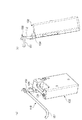
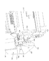
図6は、廃棄粉体回収装置100を示した図である。図6に示す廃棄粉体回収装置100は、上述した回収ボトル70に代えてプリンタ本体1(共に図2参照)に着脱自在に取り付けられる一次回収部110と、一次回収部110で回収された廃トナーおよび廃現像剤を最終的に収容する二次回収部130と、一次回収部110と二次回収部130との間で廃トナーおよび廃現像剤を搬送する搬送部150とを有している。ここで、一次回収部110はプリンタ本体1に対し、プリンタ本体1の前扉1a側からプロセスカートリッジ60の配置方向に向かって平行に着脱するように構成されている。
【0028】
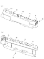
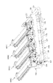
図7は一次回収部110を正面から見た図であり、図8は一次回収部110に四本のプロセスカートリッジ60を装着した状態を示す斜視図である。一次回収部110は中空状の一次回収容器(回収容器)110aを有している。一次回収容器110aには、図6および図7に示すように、不要となった廃トナーや廃現像剤を取り入れる開口111〜119が形成されている。ここで、開口111〜114には、各画像形成ユニット11Y,11M,11C,11K(図2参照)を構成するプロセスカートリッジ60に取り付けられたドラムクリーナ16(共に図4参照)で回収されオーガ16b(図3参照)により搬送された廃トナー等が搬入される。つまり開口111〜114は、廃トナー搬入口としての機能を有する。また、開口116〜119には、各画像形成ユニット11Y,11M,11C,11K(図2参照)の現像器14からオーガ14c(共に図3参照)により搬送された廃現像剤が搬入される。つまり、開口116〜119は、廃現像剤搬入口としての機能を有する。さらに、開口115には、ベルトクリーナ25(図2参照)で回収されオーガ25c(図2参照)によって搬送された廃トナー等が搬入される。つまり、開口115は、廃トナー搬入口としての機能を有する。また、開口111〜119は、廃トナーあるいは廃現像剤を一次回収容器110a内に落下させる落下手段としての機能を有する。なお、各開口111〜119には、所定形状の切り込みが入れられた漏れ防止用のスポンジが取り付けられる。
【0029】
また、一次回収容器110aの内側底部には、長手方向に沿って搬送部材としてのコイルオーガ120が配設されている。コイルオーガ120は硬鋼線にて構成され、その外径はφ16、線径はφ1、ピッチは5mmである。コイルオーガ120は、その一端が一次回収容器110aの外側に配設されたギヤ121に接続されており、他端が一次回収容器110aの下側側部に設けられた排出口122よりさらに外側まで、具体的には、搬送部150の搬送パイプ151の下流側端部まで延設されている。また、コイルオーガ120を駆動するギヤ121は、受け側カップリング124と一体的に形成されるギヤ123と噛合しており、後述するように本体側に設けられる駆動装置160から伝達される駆動力によって駆動されるようになっている。これによりコイルオーガ120は、一次回収容器110a内に搬入された廃トナーや廃現像剤を搬送パイプ151側に向けて搬送することができる。なお、図から明らかなように、搬送パイプ151は屈曲しているが、コイルオーガ120がフレキシビリティを有しているため、屈曲した搬送パイプ151内においても十分に廃トナーや廃現像剤を搬送することが可能である。
【0030】
さらに、一次回収部110には、四つの開口125〜128が並列に設けられている。これら開口125〜128は、レーザ光(LB-Y,LB-M,LB-C,LB-K)が通過するガラス製のウィンドウ33(図2参照)を清掃するためのものである。なお図6は、これら開口125〜128がプリンタ本体1に対する取り付け用の板129で隠された状態を示している。
【0031】
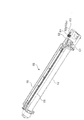
また、二次回収部130は、図6に示す筐体カバー131を有しており、その内部には、図9に示す二次回収容器132が収容されている。ここで、図9(a)は二次回収容器132および搬送部150の主要部を示す斜視図であり、図9(b)はその側面図である。
二次回収容器132は、略直方体状の形状を有し、その上部側には取っ手133が形成されている。また、二次回収容器132の上面には、廃トナーおよび廃現像剤を搬入するための開口134が形成されている。
一方、搬送部150の搬送パイプ151端部には、二次回収容器132を着脱するコネクタ152が取り付けられている。コネクタ152は、二次回収容器132を取り付けた場合に二次回収容器132内に廃トナーおよび廃現像剤を搬入でき、且つ、二次回収容器132を取り外した場合に外部に廃トナーや廃現像剤が漏れないように蓋ができるように構成されている。なお、搬送パイプ151は、図6に示すカバー153が取り付けられる。このカバー153は、プリンタ本体1(図1参照)に装着される。
【0032】
そして、本実施の形態では、図9(b)から明らかなように、二次回収容器132が所定の角度だけ傾斜した状態でコネクタ152に取り付けられるようになっている。このように二次回収容器132を配設することで、二次回収容器132内を落下する廃トナーおよび廃現像剤が、二次回収容器132の内部側壁を滑り落ちるようになるため、内部での廃トナーおよび廃現像剤の飛散を抑制することが可能となっている。
【0033】
次に、本実施の形態に係る画像形成装置の動作について説明する。図示しない原稿読み取り装置によって読み取られた原稿の色材反射光像や、図示しないパーソナルコンピュータ等にて形成された色材画像データは、例えばR(赤)、G(緑)、B(青)の各8ビットの反射率データとしてIPS50に入力される。IPS50では、入力された反射率データに対して、シェーディング補正、位置ズレ補正、明度/色空間補正、ガンマ補正、枠消しや色編集、移動編集等の各種画像編集等の画像処理が施される。画像処理が施された画像データは、イエロー(Y)、マゼンタ(M)、シアン(C)、ブラック(K)の四色の色材階調データに変換され、ROS30に出力される。
【0034】
ROS30では、入力された色材階調データに応じて、レーザダイオード(図示せず)から出射されたレーザ光(LB-Y,LB-M,LB-C,LB-K)を、f-θレンズ(図示せず)を介してポリゴンミラー31に出射している。ポリゴンミラー31では、入射されたレーザ光を各色の階調データに応じて変調し、偏向走査して、図示しない結像レンズおよび複数枚のミラーを介して画像形成ユニット11Y,11M,11C,11Kの感光体ドラム12に照射している。画像形成ユニット11Y,11M,11C,11Kの感光体ドラム12では、帯電された表面が走査露光され、静電潜像が形成される。形成された静電潜像は、各々の画像形成ユニット11Y,11M,11C,11Kにて、イエロー(Y)、マゼンタ(M)、シアン(C)、ブラック(K)の各色のトナー像として現像される。
【0035】
画像形成ユニット11Y,11M,11C,11Kの感光体ドラム12上に形成されたトナー像は、中間転写体である中間転写ベルト21上に順次転写される。このとき、ブラックのトナー像を形成するブラックの画像形成ユニット11Kは、中間転写ベルト21の移動方向の最下流側に設けられ、ブラックのトナー像は、中間転写ベルト21に対して最後に転写される。
【0036】
一方、シート搬送系40では、画像形成のタイミングに合わせてナジャーロール42が回転し、給紙装置41から所定サイズの記録用紙が供給される。フィードロール43により一枚ずつ分離された記録用紙は、搬送路44を経てレジストロール45に移送され、一旦、停止される。その後、トナー像が形成された中間転写ベルト21の移動タイミングに合わせてレジストロール45が回転し、記録用紙は、バックアップロール24および二次転写ロール46によって形成される二次転写位置に搬送される。二次転写位置にて下方から上方に向けて搬送される記録用紙には、圧接力および所定の電界を用いて、四色が重ね転写されたトナー像が副走査方向に順次、二次転写される。そして、トナー像が二次転写された記録用紙は、定着器29によって熱および圧力で定着処理を受けた後、排出ロール47によってプリンタ本体1の上部に設けられた排出トレイ48に排出される。なお、排出トレイ48にそのまま排出せずに、図示しない切り替えゲートによって記録用紙を両面用搬送ユニット49によって反転させることもできる。この反転された記録用紙をレジストロール45に搬送した後、前述と同様な流れによって、印刷されていない他の面について画像を形成することで、記録用紙の両面に画像を形成することが可能となる。
【0037】
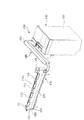
次に、この画像形成装置における一次回収部110に設けた受け側カップリング124と本体側に設けられる駆動装置160との連結について説明する。
図10は、駆動装置160と受け側カップリング124との連結を説明するための図である。駆動装置160は、駆動源であるDCモータ161、DCモータ161のモータ軸に取り付けたウォーム162、ウォーム162と噛み合って回転軸の方向をモータ軸と直交する方向へ変換するためのウォームホイール163、ウォームホイール163と同軸に結合してあるギヤ164、ギヤ164に噛合して配置されたギヤ165、ギヤ165と同軸に一体的に形成された駆動伝達部材としての駆動側カップリング166、これらを取り付け固定するべース部材167から構成されている。
駆動装置160では、DCモータ161の駆動がウォーム162からウォームホイール163へ伝達される際に約1/100に減速され、ギヤ164およびギヤ165を介して駆動側カップリング166に伝達される。
【0038】
一方、一次回収部110は駆動装置160側の側部に、一次回収容器110aの内側底部に配設されたコイルオーガ120に駆動を伝達するギヤ121、ギヤ121に噛合して配置されたギヤ123、ギヤ123と一体的に形成される駆動受け部材としての受け側カップリング124を備えている。
そして、一次回収部110が、プリンタ本体1の前扉1a側からプロセスカートリッジ60の配置方向に向かって平行に装着された際に、駆動装置160の駆動側カップリング166と一次回収部110の受け側カップリング124とは結合される。
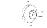
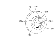
【0039】
ここで、駆動側カップリング166と受け側カップリング124とを説明する。図11は駆動側カップリング166を説明する図であり、図12は受け側カップリング124を説明する図である。図11に示すように、駆動側カップリング166はギヤ165と同軸にプラスチックによる一体成型で形成されている。駆動側カップリング166は、円盤状の基体166a、基体166aの回転中心軸から6mm離れた位置に基体166aに垂直に固設された円柱形状の柱状凸部166bで構成されている。
【0040】
また、図12に示すように、受け側カップリング124はギヤ123と同軸にプラスチックによる一体成型で形成されている。受け側カップリング124は外径が18.5mm、内径が14mmの円筒状の基体124a、基体124aの上面であって回転中心軸から離れた位置に固設された壁状凸部124b、壁状凸部124bを補強する補強部材124cで構成されている。壁状凸部124bは、断面形状が長方形と半円形とを組み合わせた小判形状に形成され、受け側カップリング124の回転方向上流側には平面に形成された側面124dが配設されている。さらに、壁状凸部124bは側面124dの法線が回転中心軸と直交する方向を向くように基体124aの上面に垂直に固設されている。
【0041】
ここで、一次回収部110をプリンタ本体1に装着させる場合を説明する。一次回収部110を装着させると、受け側カップリング124は壁状凸部124bが駆動側カップリング166の回転軸に対し直交する方向から駆動側カップリング166に結合される。その際、駆動側カップリング166の回転軸と受け側カップリング124の回転軸とは一致するように位置する。一次回収部110が装着された後には、駆動側カップリング166の回転により柱状凸部166bは壁状凸部124bの側面124dと当接する。そして、受け側カップリング124は柱状凸部166bからの駆動力を壁状凸部124bの側面124dに受けて回転する。
【0042】
このように受け側カップリング124には平面で形成された側面124dが設けられ、柱状凸部166bからの駆動力を受けている。このため、柱状凸部166bが壁状凸部側面124dに当接するに際し、柱状凸部166bからの駆動力を効率よく伝達できる当接許容域を大きく形成することができる。すなわち、壁状凸部側面124dを基体124aの法線方向に充分に長く形成することによって、壁状凸部側面124dには柱状凸部166bが確実に当接して、駆動力を効率よく伝達することができる。
【0043】
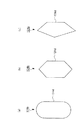
ここで、壁状凸部124bの断面形状は、柱状凸部166bが当接する側面124dが平面に形成されていればよく、図13に示すように、断面形状が例えば幅3mm、長さ3.5mmの長方形と半径1.5mmの半円形とを組み合わせた小判形状((a))のほか、長方形と三角形とを組み合わせた六角形状((b))、または五角形状((c))で形成してもよい。なお、側面124dは平面に形成するだけでなく、駆動力の伝達および受け側カップリング124の引き出しに障害とならない限り、緩やかな湾曲で形成した凸部または凹部を設けてもよい。
【0044】
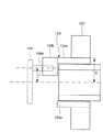
また、図14に示したように、壁状凸部124bは基体124aの外周面124eよりも内側の領域に配置されるように、壁状凸部124bの端部が基体124aの上面に位置するように固設されている。そして、駆動側カップリング166の柱状凸部166bの回転半径rは、基体124aの外周半径Rよりも大きくならないように設定し、柱状凸部166bが基体124aの外周面124eよりも内側から駆動力を伝達するように構成している。本実施の形態では、柱状凸部166bの回転半径rは6mmであり、基体124aの外周面124eの半径Rは9.25mmに設定している。なお、柱状凸部166bの回転半径rと基体124aの外周面124eの半径Rとは等しくなるように設定してもよい。
【0045】
このように構成するのは、以下の理由に基づくものである。例えば壁状凸部124bを基体124aの外周面124eよりも外側に位置するように配設し、柱状凸部166bを基体124aの外周面124eよりも外側で当接して駆動力を伝達するように構成することも考えられる。しかし、柱状凸部166bの当接位置が外周面124eよりも外側である場合、壁状凸部124bには柱状凸部166bから壁状凸部124bを固設した基体124aの上面との接合部を支点として回転方向に倒そうとする大きな力が働いてしまう。
【0046】
すなわち、柱状凸部166bが壁状凸部124bを押す力をF、壁状凸部124bを固設した基体124aの上面の接合部に働く力をfとすると、f=rF/Rで表される。したがって、r>Rの場合にはr/R>1となってfはFよりも大きな力となってしまう。このため、壁状凸部124bの接合部に大きなせん断力が働き、壁状凸部124bがこの接合部で破損するという現象が発生する。これに対し、本実施の形態のように、r≦Rの場合にはr/R≦1となってfはFよりも大きくはならない。したがって、柱状凸部166bの当接位置を基体124aの外周面124eよりも内側となるように構成することによって、壁状凸部124bを倒そうとする力を小さく抑えることが可能となる。このため、壁状凸部124bが破損するという現象は発生しない。なお、本実施の形態のように、壁状凸部124bの破損を防止するため、壁状凸部124bの回転方向下流側に、補強部材124cを配設して壁状凸部124bを補強することも有効である。
【0047】
次に、一次回収部110をプリンタ本体1から取り出す場合を説明する。駆動側カップリング166は、ウォーム162とウォームホイール163からなるウォームギヤに接続されているのでロックされた状態となることから、駆動側カップリング166側から回転させることはできない。これに対し、受け側カップリング124は構成上そのような制限を受けていないため自由に回転することが可能である。このため、一次回収部110を引き出す場合には、引き出し動作に同期して受け側カップリング124の壁状凸部124bは柱状凸部166bからすり抜けられる位置まで柱状凸部166bに押されて回転する。さらに、壁状凸部124bの側面124dは平面に形成され、柱状凸部166bは円筒形状に形成されているので、壁状凸部124bの側面124dは柱状凸部166bの円筒側面を滑ることができる。すなわち、一次回収部110を引き出す動作によって、受け側カップリング124は回転し、柱状凸部166bをすり抜け、カップリングが解除される。
【0048】
このように、駆動側カップリング166と受け側カップリング124とは、少なくとも一方がロックされた状態とならず自由に回転することが可能に構成されている。これによって、一次回収部110を引き出す場合には、引き出し動作に同期して駆動側カップリング166と受け側カップリング124とのいずれかがすり抜けられる位置まで回転することができる。なおその際、受け側カップリング124の引き出しに障害とならないように回転可能側のカップリングには側面が平面で形成された壁状凸部を配設し、固定側のカップリングには円柱形状の柱状凸部を配設することが必要である。
【0049】
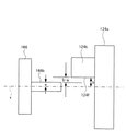
また、図15に示したように、壁状凸部124bは回転軸側端部124fの回転半径(回転最小半径)bが駆動側カップリング166の柱状凸部166bの半径aよりも大きくなるように構成されている。このように構成することによって、一次回収部110を引き出す方向から見て柱状凸部166bが回転軸xと重なる位置にある場合でも、壁状凸部124bを柱状凸部166bと回転軸xとを含む平面に対して垂直となるように位置させることでb−aのクリアランスを得ることができるので、容易に取り外すことができる。
このように、柱状凸部166bがどこに位置していようとも柱状凸部166bが障害物となることなく、受け側カップリング124は駆動側カップリング166からスムーズに取り外すことが可能である。
【0050】
なお、本実施の形態では、駆動側カップリング166には、柱状凸部166bを1本配設したが、受け側カップリング124の引き出しに障害とならない限り、複数の柱状凸部166bを配設することもできる。また、柱状凸部166bは円筒形状で形成したが、壁状凸部124bの側面124dが滑り抜けることができるような形状であれば、内角が鈍角である多角柱形状や一部に平面を有する円筒形状等で形成してもよい。
【0051】
また、駆動装置160にウォーム162とウォームホイール163からなるウォームギヤを用い、駆動側カップリング166が駆動側カップリング166側からはロックされた状態となるように構成したが、駆動側カップリング166側からロックされないように駆動ギヤを構成してもよい。
なおその際、受け側カップリング124側をロックされた状態となるようにギヤを構成してもよいが、上述したように受け側カップリング124の引き出しに障害とならないように受け側カップリング124には円柱形状の柱状凸部を配設し、駆動側カップリング166には側面が平面で形成された壁状凸部を配設することが必要である。
【0052】
さらに、本実施の形態の駆動力伝達装置は、廃棄粉体回収装置100に適用する場合に限られず、トナー供給装置等の駆動力を伝達する機構を備えた本体装置に着脱自在なユニット全てに適用可能である。
【0053】
【発明の効果】
以上説明したように、本発明によれば、着脱可能なユニットに駆動力を効率よく伝達することが可能となった。
【図面の簡単な説明】
【図1】実施の一形態に係る画像形成装置の全体構成を示す図である。
【図2】プリンタ本体を示す図である。
【図3】画像形成ユニットの構成を示す図である。
【図4】プロセスカートリッジを示す図である。
【図5】(a)(b)は回収ボトルを示す図である。
【図6】廃棄粉体回収装置を示す図である。
【図7】一次回収部を正面から見た図である。
【図8】一次回収部に四本のプロセスカートリッジを装着した状態を示す図である。
【図9】(a)は二次回収容器および搬送部の主要部を示す斜視図であり、(b)はその側面図である。
【図10】駆動装置と受け側カップリングとの連結を説明するための斜視図である。
【図11】駆動側カップリングを説明する斜視図である。
【図12】受け側カップリングを説明する斜視図である。
【図13】壁状凸部の断面形状を説明する図である。
【図14】柱状凸部と壁状凸部との位置関係を説明する図である。
【図15】壁状凸部の配置構成と柱状凸部の径との関係を説明する図である。
【符号の説明】
1…プリンタ本体、10…画像プロセス系、11Y…イエロー画像形成ユニット、11M…マゼンタ画像形成ユニット、11C…シアン画像形成ユニット、11K…ブラック画像形成ユニット、12…感光体ドラム、13…帯電器、14…現像器、15…一次転写ロール、16…ドラムクリーナ、20…転写ユニット、25…ベルトクリーナ、30…ROS、40…シート搬送系、50…IPS、60…プロセスカートリッジ、70…回収ボトル、100…廃棄粉体回収装置、110…一次回収部、110a…一次回収容器、111〜119…開口、120…コイルオーガ、124…受け側カップリング、124a…基体、124b…壁状凸部、124c…補強部材、124d…側面、124e…外周面、130…二次回収部、132…二次回収容器、150…搬送部、151…搬送パイプ、152…コネクタ、D…廃現像剤、T…廃トナー、161…DCモータ、162…ウォーム、163…ウォームホイール、164,165…ギヤ、166…駆動側カップリング、166a…基体、166b…柱状凸部、167…べース部材[0001]
TECHNICAL FIELD OF THE INVENTION
The present invention relates to a driving force transmitting device that is used in an image forming apparatus such as a copying machine, a printer, a facsimile, and the like, and that transmits drive to a detachable unit that requires rotation.
[0002]
[Prior art]
As a conventional image forming apparatus, an image carrier (e.g., a photosensitive drum) that forms and carries a toner image obtained by developing an electrostatic latent image with a developing device, and an intermediate transfer body that is arranged to face the photosensitive drum (Intermediate transfer belt), a primary transfer device that transfers the toner image on the photosensitive drum onto the intermediate transfer belt, and a secondary transfer device that transfers the toner image on the intermediate transfer belt to a recording medium (for example, paper). There are things to prepare.
In such an image forming apparatus, since the toner remains on the photosensitive drum after the primary transfer, the remaining toner is cleaned and removed by a drum cleaner, and then the next toner image is formed. Further, since the toner remains on the intermediate transfer belt after the secondary transfer, the remaining toner is cleaned and removed by a belt cleaner, and then the next toner image is transferred. The residual toner (waste toner) collected by the drum cleaner or the belt cleaner is conveyed and collected in a collection container.
[0003]
Particularly, in a color image forming apparatus, usually, four photosensitive drums for forming yellow (Y), magenta (M), cyan (C), and black (K) images are arranged around the intermediate transfer belt. Then, waste toner is generated from a drum cleaner disposed on each photosensitive drum. In order to collect these waste toners of Y, M, C, and K collectively in one collection container, waste toners that convey waste toner from the Y, M, C, and K drum cleaners or belt cleaners to the collection container are collected. A transport unit is provided. The waste toner transport unit is configured to be detachable from the image forming apparatus main body due to the need for maintenance, and is configured such that a driving force is transmitted from the image forming apparatus main body to the transport member for toner transport by a coupling. ing.
[0004]
When a two-component developer having a toner and a carrier is used as a developer, a toner container unit for replenishing the toner to the developing device is detachably provided to the image forming apparatus main body. A driving force is transmitted from a main body of the image forming apparatus to a conveying member that conveys the discharged toner to the developing device by a coupling.
[0005]
In a unit such as the waste toner conveying unit or the toner container unit which needs to transmit the driving force, the unit is coaxially connected to a driving shaft provided on the image forming apparatus main body in consideration of the transmission efficiency of the driving force. For this reason, a method of attaching and detaching the image forming apparatus to and from the image forming apparatus main body in a direction parallel to the drive shaft is adopted.
[0006]
Here, as a conventional technique, in a state where the developing cartridge is mounted on a rotary unit provided in the image forming apparatus main body, the driving force receiving portion of the developing cartridge is located coaxially with the drive transmitting member of the image forming apparatus main body, There is a technology in which a drive transmission member and a driving force receiving portion are coupled by coupling (for example, see Patent Document 1). In addition, there is a technology in which a coupling gear that rotates integrally with a toner supply roller of a developing device rotates substantially coaxially with a joint drive shaft provided on an apparatus main body and an Oldham joint at the end thereof (for example, see Patent Document 2).
[0007]
[Patent Document 1]
JP-A-9-297443 (page 17, FIG. 11)
[Patent Document 2]
JP-A-2000-227690 (
[0008]
[Problems to be solved by the invention]
By the way, for units that need to transmit the driving force, such as the waste toner transport unit and the toner container unit, depending on the arrangement of the image forming apparatus, the units may be attached and detached in a direction parallel to the drive shaft provided on the image forming apparatus main body side. Due to the difficulty in mounting, there is a case where a configuration for detaching from a direction orthogonal to the drive shaft is adopted. However, in a coupling configuration that can be moved from a direction perpendicular to the drive shaft, a method combining gears is used. In such a method, unless the distance between the gears is set with high accuracy, so-called tooth skipping occurs. And the driving force cannot be transmitted efficiently. In addition, in the case of adopting a method of attaching and detaching in a direction parallel to the drive shaft, a two-stage operation of performing a mounting operation in a direction parallel to the drive shaft after a mounting operation in a direction perpendicular to the drive shaft. Is required, and there is a problem that the attaching / detaching operation becomes complicated.
[0009]
The present invention has been made to solve the above technical problem, and an object of the present invention is to efficiently transmit a driving force to a detachable unit. Still another object is to improve operability in attaching and detaching the unit when mounting the unit.
[0010]
[Means for Solving the Problems]
In the drive transmission device of the present invention, a drive force transmission member having a drive-side convex portion disposed on the rotatable substrate in parallel with and away from the rotation axis, and disposed on the rotatable substrate away from the rotation shaft When the driving force receiving member is pulled out from the driving force transmitting member in a direction orthogonal to the rotation axis, the receiving side convex portion is driven on the driving side. The coupling is configured to be released by slipping through the projection. Thus, the driving force can be efficiently transmitted to the detachable unit.
That is, the driving force transmission device of the present invention includes a driving force transmission member having a driving side convex portion disposed on a rotatable base in parallel with the rotation axis and separated from the rotation axis; A driving force receiving member having a receiving side convex portion disposed apart from the driving force transmitting member, and the receiving side convex portion is driven when the driving force receiving member is pulled out from the driving force transmitting member in a direction orthogonal to the rotation axis. It is characterized in that it is configured to pass through the side convex portion.
[0011]
Further, the driving force transmitting device of the present invention is arranged on a rotatable base body in parallel with the rotation axis and away from the rotation axis, and has a columnar shape having a circular cross section or a polygon having an obtuse interior angle. A driving force transmitting member having a convex portion, and a wall-shaped convex portion provided on a rotatable substrate at a distance from the rotation axis, and having a plane on the upstream side in the rotation direction whose normal line is orthogonal to the rotation axis. And a driving force receiving member provided with: Further, the driving force receiving member may be configured to be rotatable from the driving transmission receiving member side. Further, the driving force transmitting member may be characterized by receiving rotational driving from a driving source via a worm gear. Further, the driving force receiving member may be characterized in that the minimum rotation radius of the wall-shaped convex portion is larger than the cross-sectional radius of the columnar convex portion of the driving force transmitting member. Further, the driving force transmitting member may be characterized in that one or more columnar protrusions are provided.
[0012]
In addition, the drive transmission device of the present invention includes a wall-shaped convex portion that is disposed on the rotatable base body at a distance from the rotation axis, and that has a plane formed with a normal line perpendicular to the rotation axis on the upstream side in the rotation direction. A driving force transmitting member provided with a column-shaped convex portion which is disposed on a rotatable base body in parallel with the rotating shaft and separated from the rotating shaft, and has a circular cross section or a polygonal shape having an obtuse interior angle. And a driving force receiving member provided. Further, the driving force transmission member may be configured to be rotatable from the driving force transmission member side.
[0013]
Further, the drive transmission device of the present invention is arranged such that a column-shaped projection is disposed on a rotatable base in parallel with the rotation axis and away from the rotation axis, and has a circular cross section or a polygon having an obtuse interior angle. A driving force transmitting member having a portion and a wall-shaped convex portion, which is disposed on the rotatable base body at a distance from the rotation axis, and has a plane formed on the upstream side in the rotation direction with a normal line perpendicular to the rotation axis. The joint portion between the base and the wall-shaped protrusion is disposed outside the column including the rotation radius of the columnar protrusion of the driving force transmitting member.
[0014]
Further, the present invention is regarded as an image forming apparatus, and includes a driving source, and a driving force transmitting member having a driving-side convex portion provided on a base rotatable by the driving source and separated from the rotation axis in parallel with the rotation axis. When pulling out a unit provided with a driving force receiving member having a receiving-side convex portion provided on a rotatable base and separated from the rotation axis, in a direction orthogonal to the rotation axis from the driving force transmission member. The receiving side convex portion is configured to pass through the driving side convex portion.
[0015]
Further, the image forming apparatus according to the present invention is a multi-layered image forming apparatus, wherein the driving source and the base rotatable by the driving source are arranged apart from the rotation axis in parallel with the rotation axis, and have a circular cross section or an obtuse internal angle. A driving force transmitting member having a prismatic columnar portion formed in a rectangular shape, and disposed at a distance from the rotation axis on the rotatable base, and a plane whose normal is orthogonal to the rotation axis on the upstream side in the rotation direction. A driving force receiving member having the formed wall-shaped convex portion is provided, and a unit for forming the coupling by coupling the driving force receiving member to the driving force transmitting member is detachably configured. In particular, the unit may be provided with a waste powder recovery device. Further, the unit may include a toner supply device.
[0016]
BEST MODE FOR CARRYING OUT THE INVENTION
Hereinafter, embodiments will be described in detail with reference to the accompanying drawings.
FIG. 1 is a diagram illustrating an overall configuration of an image forming apparatus according to an embodiment. The image forming apparatus shown in FIG. 1 has a printer
[0017]
FIG. 2 is a diagram illustrating the printer
[0018]
The
[0019]
The
[0020]
The
[0021]
The
[0022]
Next, the
[0023]
The
[0024]
In the present embodiment, a two-component developing method using a so-called two-component developer (hereinafter, referred to as a developer) having a toner and a carrier in the developing
[0025]
In the present embodiment, the
[0026]
Further, in the printer
[0027]
FIG. 6 is a diagram showing the waste
[0028]
FIG. 7 is a front view of the
[0029]
In addition, a
[0030]
Further, the
[0031]
The
The
On the other hand, a
[0032]
In the present embodiment, as is apparent from FIG. 9B, the
[0033]
Next, the operation of the image forming apparatus according to the present embodiment will be described. A color material reflected light image of a document read by a document reading device (not shown) and color material image data formed by a personal computer (not shown) include, for example, R (red), G (green), and B (blue). The data is input to the
[0034]
The
[0035]
The toner images formed on the
[0036]
On the other hand, in the
[0037]
Next, the connection between the receiving-
FIG. 10 is a diagram for explaining the connection between the driving
In the
[0038]
On the other hand, the
When the
[0039]
Here, the driving
[0040]
Further, as shown in FIG. 12, the receiving-
[0041]
Here, a case where the
[0042]
As described above, the receiving-
[0043]
Here, the cross-sectional shape of the wall-shaped
[0044]
As shown in FIG. 14, the end of the wall-shaped
[0045]
Such a configuration is based on the following reasons. For example, the wall-shaped
[0046]
That is, assuming that the force by which the columnar
[0047]
Next, a case where the
[0048]
As described above, at least one of the drive-
[0049]
As shown in FIG. 15, the wall-shaped
In this way, the receiving-
[0050]
In the present embodiment, one column-shaped
[0051]
Further, a worm gear including a
At this time, the gear may be configured so that the receiving
[0052]
Further, the driving force transmission device of the present embodiment is not limited to the case where the driving force transmission device is applied to the waste
[0053]
【The invention's effect】
As described above, according to the present invention, it has become possible to efficiently transmit a driving force to a detachable unit.
[Brief description of the drawings]
FIG. 1 is a diagram illustrating an overall configuration of an image forming apparatus according to an embodiment.
FIG. 2 is a diagram illustrating a printer main body.
FIG. 3 is a diagram illustrating a configuration of an image forming unit.
FIG. 4 is a diagram illustrating a process cartridge.
FIGS. 5A and 5B are diagrams showing a collection bottle.
FIG. 6 is a diagram showing a waste powder recovery device.
FIG. 7 is a front view of the primary collection unit.
FIG. 8 is a diagram illustrating a state in which four process cartridges are mounted on a primary recovery unit.
FIG. 9A is a perspective view illustrating a main part of a secondary collection container and a transport unit, and FIG. 9B is a side view thereof.
FIG. 10 is a perspective view for explaining connection between a driving device and a receiving-side coupling.
FIG. 11 is a perspective view illustrating a drive-side coupling.
FIG. 12 is a perspective view illustrating a receiving-side coupling.
FIG. 13 is a diagram illustrating a cross-sectional shape of a wall-shaped convex portion.
FIG. 14 is a diagram illustrating a positional relationship between a columnar convex portion and a wall-shaped convex portion.
FIG. 15 is a diagram illustrating the relationship between the arrangement of wall-shaped protrusions and the diameter of columnar protrusions.
[Explanation of symbols]
DESCRIPTION OF
Claims (13)
回転可能な基体に回転軸とは離れて配設された受け側凸部を有する駆動力受け部材とを備え、
前記駆動力受け部材を前記駆動力伝達部材から前記回転軸に対し直交する方向に引き抜く際に、前記受け側凸部が前記駆動側凸部をすり抜けるように構成されたことを特徴とする駆動力伝達装置。A driving force transmitting member having a driving-side convex portion disposed on the rotatable substrate in parallel with the rotation axis and away from the rotation axis,
A driving force receiving member having a receiving-side convex portion disposed apart from the rotation axis on the rotatable base,
When the driving force receiving member is pulled out from the driving force transmitting member in a direction orthogonal to the rotation axis, the driving force receiving member is configured to pass through the driving side protrusion. Transmission device.
回転可能な基体に回転軸とは離れて配設されるともに、回転方向上流側に法線が当該回転軸と直交する平面が形成された壁状凸部を備えた駆動力受け部材と
から構成されたことを特徴とする駆動力伝達装置。A driving force transmission member provided with a columnar protrusion formed in a rotatable base in parallel with the rotation axis and away from the rotation axis, and having a polygonal cross-section having a circular shape or an obtuse angle. ,
A driving force receiving member that is provided on the rotatable substrate at a distance from the rotation axis and that has a wall-shaped convex portion on the upstream side in the rotation direction, the wall having a plane whose normal line is orthogonal to the rotation axis. A driving force transmission device characterized by being performed.
回転可能な基体に回転軸と平行に当該回転軸とは離れて配設されるともに、断面形状が円形または内角が鈍角である多角形で形成された柱状凸部を備えた駆動力受け部材と
から構成されたことを特徴とする駆動力伝達装置。A driving force transmission member provided with a wall-shaped convex portion, which is disposed on the rotatable base away from the rotation shaft, and has a plane on the upstream side in the rotation direction, the normal line of which is orthogonal to the rotation shaft;
A driving force receiving member provided with a columnar convex portion formed in a rotatable base in parallel with the rotation axis and away from the rotation shaft, and having a polygonal cross section having a circular shape or an obtuse interior angle; A driving force transmission device comprising:
回転可能な基体に回転軸とは離れて配設されるともに、回転方向上流側に法線が当該回転軸と直交する平面が形成された壁状凸部であって、当該基体と当該壁状凸部との接合部が前記駆動力伝達部材の前記柱状凸部の回転半径を含んだ外側に配置されたことを特徴とする駆動力伝達装置。A driving force transmission member provided with a columnar protrusion formed in a rotatable base in parallel with the rotation axis and away from the rotation axis, and having a polygonal cross-section having a circular shape or an obtuse angle. ,
A wall-shaped projection that is disposed on the rotatable base body at a distance from the rotation axis and that has a plane on the upstream side in the rotation direction whose normal line is orthogonal to the rotation axis; A driving force transmitting device, wherein a joint portion with the convex portion is disposed outside of the driving force transmitting member including a rotation radius of the columnar convex portion.
前記駆動源により回転可能な基体に回転軸と平行に当該回転軸とは離れて配設された駆動側凸部を有する駆動力伝達部材とを備え、
回転可能な基体に回転軸とは離れて配設された受け側凸部を有する駆動力受け部材が配設されたユニットを、前記駆動力伝達部材から前記回転軸に対し直交する方向に引き抜く際に、前記受け側凸部が前記駆動側凸部をすり抜けるように構成されたことを特徴とする画像形成装置。A driving source,
A driving force transmitting member having a driving-side convex portion disposed on the substrate rotatable by the driving source and separated from the rotation axis in parallel with the rotation axis;
When pulling out a unit in which a driving force receiving member having a receiving-side convex portion provided on a rotatable base and spaced apart from a rotation axis is disposed in a direction perpendicular to the rotation axis from the driving force transmission member. An image forming apparatus, wherein the receiving-side convex portion is configured to pass through the driving-side convex portion.
前記駆動源により回転可能な基体に回転軸と平行に当該回転軸とは離れて配設されるともに、断面形状が円形または内角が鈍角である多角形で形成された柱状凸部を有する駆動力伝達部材とを備え、
回転可能な基体に回転軸とは離れて配設されるともに、回転方向上流側に法線が当該回転軸と直交する平面が形成された壁状凸部を有する駆動力受け部材が配設され、当該駆動力受け部材が前記駆動力伝達部材と結合してカップリングを形成するユニットが着脱自在に構成されたことを特徴とする画像形成装置。A driving source,
A driving force that is disposed on a substrate rotatable by the drive source in a direction parallel to the rotation axis and separated from the rotation axis, and that has a columnar convex portion formed in a polygonal shape having a circular cross section or an obtuse internal angle; And a transmission member,
A driving force receiving member is provided on the rotatable base member, the driving force receiving member having a wall-shaped convex portion on the upstream side in the rotation direction, the wall having a plane perpendicular to the rotation axis. An image forming apparatus, wherein a unit for forming the coupling by coupling the driving force receiving member with the driving force transmitting member is detachably configured.
Priority Applications (1)
| Application Number | Priority Date | Filing Date | Title |
|---|---|---|---|
| JP2002368540A JP2004198822A (en) | 2002-12-19 | 2002-12-19 | Driving force transmitting device and image forming apparatus |
Applications Claiming Priority (1)
| Application Number | Priority Date | Filing Date | Title |
|---|---|---|---|
| JP2002368540A JP2004198822A (en) | 2002-12-19 | 2002-12-19 | Driving force transmitting device and image forming apparatus |
Related Child Applications (1)
| Application Number | Title | Priority Date | Filing Date |
|---|---|---|---|
| JP2008292097A Division JP4557077B2 (en) | 2008-11-14 | 2008-11-14 | Image forming apparatus |
Publications (1)
| Publication Number | Publication Date |
|---|---|
| JP2004198822A true JP2004198822A (en) | 2004-07-15 |
Family
ID=32765080
Family Applications (1)
| Application Number | Title | Priority Date | Filing Date |
|---|---|---|---|
| JP2002368540A Pending JP2004198822A (en) | 2002-12-19 | 2002-12-19 | Driving force transmitting device and image forming apparatus |
Country Status (1)
| Country | Link |
|---|---|
| JP (1) | JP2004198822A (en) |
Cited By (8)
| Publication number | Priority date | Publication date | Assignee | Title |
|---|---|---|---|---|
| JP2006208464A (en) * | 2005-01-25 | 2006-08-10 | Ricoh Co Ltd | Image forming apparatus |
| US8275286B2 (en) | 2006-12-22 | 2012-09-25 | Canon Kabushiki Kaisha | Process cartridge, electrophotographic image forming apparatus, and electrophotographic photosensitive drum unit |
| US8295734B2 (en) | 2006-12-22 | 2012-10-23 | Canon Kabushiki Kaisha | Rotational force transmitting parts |
| US8437669B2 (en) | 2007-03-23 | 2013-05-07 | Canon Kabushiki Kaisha | Electrophotographic image forming apparatus, developing apparatus, and coupling member |
| US9477201B2 (en) | 2008-06-20 | 2016-10-25 | Canon Kabushiki Kaisha | Cartridge, mounting method for coupling member, and disassembling method for coupling member |
| JP2017040823A (en) * | 2015-08-20 | 2017-02-23 | キヤノン株式会社 | Image forming apparatus |
| US11079713B1 (en) | 2017-12-21 | 2021-08-03 | Hewlett-Packard Development Company, L.P. | Cartridge having rotatable coupler |
| JP2022141548A (en) * | 2021-03-15 | 2022-09-29 | キヤノン株式会社 | image forming device |
Citations (5)
| Publication number | Priority date | Publication date | Assignee | Title |
|---|---|---|---|---|
| JPH04250476A (en) * | 1991-01-28 | 1992-09-07 | Fuji Xerox Co Ltd | Toner supplying device with toner cartridge |
| JPH06193640A (en) * | 1992-12-21 | 1994-07-15 | Ricoh Co Ltd | Driving force transmitting coupling |
| JPH07228372A (en) * | 1994-02-21 | 1995-08-29 | Toshiba Corp | Paper feeder |
| JPH0916023A (en) * | 1995-06-30 | 1997-01-17 | Toshiba Corp | Driving device for image carrier and image forming apparatus including the driving device |
| JPH10105026A (en) * | 1996-09-30 | 1998-04-24 | Canon Inc | Process cartridge and electrophotographic image forming apparatus |
-
2002
- 2002-12-19 JP JP2002368540A patent/JP2004198822A/en active Pending
Patent Citations (5)
| Publication number | Priority date | Publication date | Assignee | Title |
|---|---|---|---|---|
| JPH04250476A (en) * | 1991-01-28 | 1992-09-07 | Fuji Xerox Co Ltd | Toner supplying device with toner cartridge |
| JPH06193640A (en) * | 1992-12-21 | 1994-07-15 | Ricoh Co Ltd | Driving force transmitting coupling |
| JPH07228372A (en) * | 1994-02-21 | 1995-08-29 | Toshiba Corp | Paper feeder |
| JPH0916023A (en) * | 1995-06-30 | 1997-01-17 | Toshiba Corp | Driving device for image carrier and image forming apparatus including the driving device |
| JPH10105026A (en) * | 1996-09-30 | 1998-04-24 | Canon Inc | Process cartridge and electrophotographic image forming apparatus |
Cited By (68)
| Publication number | Priority date | Publication date | Assignee | Title |
|---|---|---|---|---|
| JP2006208464A (en) * | 2005-01-25 | 2006-08-10 | Ricoh Co Ltd | Image forming apparatus |
| US9874846B2 (en) | 2006-12-22 | 2018-01-23 | Canon Kabushiki Kaisha | Process cartridge, electrophotographic image forming apparatus, and electrophotographic photosensitive drum unit |
| US8275286B2 (en) | 2006-12-22 | 2012-09-25 | Canon Kabushiki Kaisha | Process cartridge, electrophotographic image forming apparatus, and electrophotographic photosensitive drum unit |
| US8295734B2 (en) | 2006-12-22 | 2012-10-23 | Canon Kabushiki Kaisha | Rotational force transmitting parts |
| US12405567B2 (en) | 2006-12-22 | 2025-09-02 | Canon Kabushiki Kaisha | Process cartridge, electrophotographic image forming apparatus, and electrophotographic photosensitive drum unit |
| US8452210B2 (en) | 2006-12-22 | 2013-05-28 | Canon Kabushiki Kaisha | Rotational force transmitting part |
| US8532533B2 (en) | 2006-12-22 | 2013-09-10 | Canon Kabushiki Kaisha | Rotational force transmitting part |
| US8630564B2 (en) | 2006-12-22 | 2014-01-14 | Canon Kabushiki Kaisha | Process cartridge electrophotographic image forming apparatus, and electrophotographic photosensitive drum unit |
| US9176468B2 (en) | 2006-12-22 | 2015-11-03 | Canon Kabushiki Kaisha | Rotational force transmitting part |
| US11720054B2 (en) | 2006-12-22 | 2023-08-08 | Canon Kabushiki Kaisha | Process cartridge, electrophotographic image forming apparatus, and electrophotographic photosensitive drum unit |
| US11237517B2 (en) | 2006-12-22 | 2022-02-01 | Canon Kabushiki Kaisha | Process cartridge, electrophotographic image forming apparatus, and electrophotographic photosensitive drum unit |
| US11156956B2 (en) | 2006-12-22 | 2021-10-26 | Canon Kabushiki Kaisha | Rotational force transmitting part |
| US9678471B2 (en) | 2006-12-22 | 2017-06-13 | Canon Kabushiki Kaisha | Process cartridge, electrophotographic image forming apparatus, and electrophotographic photosensitive drum unit |
| US10877433B2 (en) | 2006-12-22 | 2020-12-29 | Canon Kabushiki Kaisha | Process cartridge, electrophotographic image forming apparatus, and electrophotographic photosensitive drum unit |
| US9733614B2 (en) | 2006-12-22 | 2017-08-15 | Canon Kabushiki Kaisha | Process cartridge, electrophotographic image forming apparatus, and electrophotographic photosensitive drum unit |
| US9746826B2 (en) | 2006-12-22 | 2017-08-29 | Canon Kabushiki Kaisha | Process cartridge, electrophotographic image forming apparatus, and electrophotographic photosensitive drum unit |
| US9772602B2 (en) | 2006-12-22 | 2017-09-26 | Canon Kabushiki Kaisha | Rotational force transmitting part |
| US9874854B2 (en) | 2006-12-22 | 2018-01-23 | Canon Kabushiki Kaisha | Process cartridge, electrophotographic image forming apparatus, and electrophotographic photosensitive drum unit |
| US10209670B2 (en) | 2006-12-22 | 2019-02-19 | Canon Kabushiki Kaisha | Rotational force transmitting part |
| US10845756B2 (en) | 2006-12-22 | 2020-11-24 | Canon Kabushiki Kaisha | Rotational force transmitting part |
| US9841729B2 (en) | 2006-12-22 | 2017-12-12 | Canon Kabushiki Kaisha | Process cartridge, electrophotographic image forming apparatus, and electrophotographic photosensitive drum unit |
| US9841727B2 (en) | 2006-12-22 | 2017-12-12 | Canon Kabushiki Kaisha | Process cartridge, electrophotographic image forming apparatus, and electrophotographic photosensitive drum unit |
| US9841728B2 (en) | 2006-12-22 | 2017-12-12 | Canon Kabushiki Kaisha | Process cartridge having changeable relative positioning of a coupling member and another part of the process cartridge |
| US10671018B2 (en) | 2006-12-22 | 2020-06-02 | Canon Kabushiki Kaisha | Process cartridge, electrophotographic image forming apparatus, and electrophotographic photosensitive drum unit |
| US9846408B2 (en) | 2006-12-22 | 2017-12-19 | Canon Kabushiki Kaisha | Process cartridge, electrophotographic image forming apparatus, and electrophotographic photosensitive drum unit |
| US10585391B2 (en) | 2006-12-22 | 2020-03-10 | Canon Kabushiki Kaisha | Process cartridge, electrophotographic image forming apparatus, and electrophotographic photosensitive drum unit |
| US10551793B2 (en) | 2006-12-22 | 2020-02-04 | Canon Kabushiki Kaisha | Process cartridge, electrophotographic image forming apparatus, and electrophotographic photosensitive drum unit |
| US9857764B2 (en) | 2006-12-22 | 2018-01-02 | Canon Kabushiki Kaisha | Process cartridge, electrophotographic image forming apparatus, and electrophotographic photosensitive drum unit |
| US10539924B2 (en) | 2006-12-22 | 2020-01-21 | Canon Kabushiki Kaisha | Process cartridge, electrophotographic image forming apparatus, and electrophotographic photosensitive drum unit |
| US9857765B2 (en) | 2006-12-22 | 2018-01-02 | Canon Kabushiki Kaisha | Process cartridge, electrophotographic image forming apparatus, and electrophotographic photosensitive drum unit |
| US9864331B2 (en) | 2006-12-22 | 2018-01-09 | Canon Kabushiki Kaisha | Process cartridge, electrophotographic image forming apparatus, and electrophotographic photosensitive drum unit |
| US9864333B2 (en) | 2006-12-22 | 2018-01-09 | Canon Kabushiki Kaisha | Process cartridge, electrophotographic image forming apparatus, and electrophotographic photosensitive drum unit |
| US9869960B2 (en) | 2006-12-22 | 2018-01-16 | Canon Kabushiki Kaisha | Process cartridge, electrophotographic image forming apparatus, and electrophotographic photosensitive drum unit |
| US8280278B2 (en) | 2006-12-22 | 2012-10-02 | Canon Kabushiki Kaisha | Process cartridge, electrophotographic image forming apparatus, and electrophotographic photosensitive drum unit |
| US10539923B2 (en) | 2006-12-22 | 2020-01-21 | Canon Kabushiki Kaisha | Process cartridge, electrophotographic image forming apparatus, and electrophotographic photosensitive drum unit |
| US9836021B2 (en) | 2006-12-22 | 2017-12-05 | Canon Kabushiki Kaisha | Process cartridge, electrophotographic image forming apparatus, and electrophotographic photosensitive drum unit |
| US10429794B2 (en) | 2006-12-22 | 2019-10-01 | Canon Kabushiki Kaisha | Rotational force transmitting part |
| US9817333B2 (en) | 2007-03-23 | 2017-11-14 | Canon Kabushiki Kaisha | Electrophotographic image forming apparatus, developing apparatus, and coupling member |
| US10795312B2 (en) | 2007-03-23 | 2020-10-06 | Canon Kabushiki Kaisha | Electrophotographic image forming apparatus, developing apparatus, and coupling member |
| US9939776B2 (en) | 2007-03-23 | 2018-04-10 | Canon Kabushiki Kaisha | Electrophotographic image forming apparatus, developing apparatus, and coupling member |
| US10520887B2 (en) | 2007-03-23 | 2019-12-31 | Canon Kabushiki Kaisha | Electrophotographic image forming apparatus, developing apparatus, and coupling member |
| US9886002B2 (en) | 2007-03-23 | 2018-02-06 | Canon Kabushiki Kaisha | Electrophotographic image forming apparatus, developing apparatus, and coupling member |
| US9857766B2 (en) | 2007-03-23 | 2018-01-02 | Canon Kabushiki Kaisha | Electrophotographic image forming apparatus, developing apparatus, and coupling member |
| US8437669B2 (en) | 2007-03-23 | 2013-05-07 | Canon Kabushiki Kaisha | Electrophotographic image forming apparatus, developing apparatus, and coupling member |
| US9851685B2 (en) | 2007-03-23 | 2017-12-26 | Canon Kabushiki Kaisha | Electrophotographic image forming apparatus, developing apparatus, and coupling member |
| US9851688B2 (en) | 2007-03-23 | 2017-12-26 | Canon Kabushiki Kaisha | Electrophotographic image forming apparatus, developing apparatus, and coupling member |
| US10620582B2 (en) | 2007-03-23 | 2020-04-14 | Canon Kabushiki Kaisha | Electrophotographic image forming apparatus, developing apparatus, and coupling member |
| US9841724B2 (en) | 2007-03-23 | 2017-12-12 | Canon Kabushiki Kaisha | Image forming apparatus cartridge having changeable relative positioning of a coupling member and another part of the image forming apparatus cartridge |
| US10712709B2 (en) | 2007-03-23 | 2020-07-14 | Canon Kabushiki Kaisha | Electrophotographic image forming apparatus, developing apparatus, and coupling member |
| US10712710B2 (en) | 2007-03-23 | 2020-07-14 | Canon Kabushiki Kaisha | Electrophotographic image forming apparatus, developing apparatus, and coupling member |
| US10788790B2 (en) | 2007-03-23 | 2020-09-29 | Canon Kabushiki Kaisha | Electrophotographic image forming apparatus, developing apparatus, and coupling member |
| US10788789B2 (en) | 2007-03-23 | 2020-09-29 | Canon Kabushiki Kaisha | Electrophotographic image forming apparatus, developing apparatus, and coupling member |
| US12298704B2 (en) | 2007-03-23 | 2025-05-13 | Canon Kabushiki Kaisha | Electrophotographic image forming apparatus, developing apparatus, and coupling member |
| US10816931B2 (en) | 2007-03-23 | 2020-10-27 | Canon Kabushiki Kaisha | Electrophotographic image forming apparatus, developing apparatus, and coupling member |
| US9836015B2 (en) | 2007-03-23 | 2017-12-05 | Canon Kabushiki Kaisha | Electrophotographic image forming apparatus, developing apparatus, and coupling member |
| US9703257B2 (en) | 2007-03-23 | 2017-07-11 | Canon Kabushiki Kaisha | Electrophotographic image forming apparatus, developing apparatus, and coupling member |
| US11675308B2 (en) | 2007-03-23 | 2023-06-13 | Canon Kabushiki Kaisha | Electrophotographic image forming apparatus, developing apparatus, and coupling member |
| US11204584B2 (en) | 2007-03-23 | 2021-12-21 | Canon Kabushiki Kaisha | Electrophotographic image forming apparatus, developing apparatus, and coupling member |
| US9594343B2 (en) | 2008-06-20 | 2017-03-14 | Canon Kabushiki Kaisha | Cartridge, mounting method for coupling member, and disassembling method for coupling member |
| US11209772B2 (en) | 2008-06-20 | 2021-12-28 | Canon Kabushiki Kaisha | Cartridge, mounting method for coupling member, and disassemblying method for coupling member |
| US10901360B2 (en) | 2008-06-20 | 2021-01-26 | Canon Kabushiki Kaisha | Cartridge, mounting method for coupling member, and disassembling method for coupling member |
| US9477201B2 (en) | 2008-06-20 | 2016-10-25 | Canon Kabushiki Kaisha | Cartridge, mounting method for coupling member, and disassembling method for coupling member |
| US10095179B2 (en) | 2008-06-20 | 2018-10-09 | Canon Kabushiki Kaisha | Cartridge, mounting method for coupling member, and disassembling method for coupling member |
| US10545450B2 (en) | 2008-06-20 | 2020-01-28 | Canon Kabushiki Kaisha | Cartridge, mounting method for coupling member, and disassembling method for coupling member |
| JP2017040823A (en) * | 2015-08-20 | 2017-02-23 | キヤノン株式会社 | Image forming apparatus |
| US11079713B1 (en) | 2017-12-21 | 2021-08-03 | Hewlett-Packard Development Company, L.P. | Cartridge having rotatable coupler |
| JP2022141548A (en) * | 2021-03-15 | 2022-09-29 | キヤノン株式会社 | image forming device |
| JP7665362B2 (en) | 2021-03-15 | 2025-04-21 | キヤノン株式会社 | Image forming device |
Similar Documents
| Publication | Publication Date | Title |
|---|---|---|
| US9146499B2 (en) | Toner container and image forming apparatus with a mechanism to secure the toner container | |
| EP1890199A2 (en) | Image forming apparatus and developing agent cartridge | |
| JP4812658B2 (en) | Waste toner collecting container and image forming apparatus using the same | |
| JP4606279B2 (en) | Waste developer collection container for image forming apparatus | |
| JP2004198822A (en) | Driving force transmitting device and image forming apparatus | |
| JP4380309B2 (en) | Image forming apparatus | |
| JP3948400B2 (en) | Image forming apparatus, toner collection bottle | |
| JP4176698B2 (en) | Waste developer recovery device and image forming apparatus having the same | |
| JP4039231B2 (en) | Image forming apparatus | |
| JP3922174B2 (en) | Image forming apparatus | |
| JP3933045B2 (en) | Image forming apparatus | |
| JP2004198891A (en) | Waste powder carrying device and image forming apparatus | |
| US7912409B2 (en) | Toner cartridge | |
| JPH09211947A (en) | Developer container and developer supplying device | |
| JP4557077B2 (en) | Image forming apparatus | |
| JP3979444B2 (en) | Image forming apparatus | |
| JP2013205694A (en) | Image forming apparatus | |
| CN102193411A (en) | Toner cartridge and image forming device including the same | |
| JP4265635B2 (en) | Image forming apparatus and toner collection bottle | |
| JP4530100B2 (en) | Image forming apparatus and developer containing member used therefor | |
| JP4530099B2 (en) | Image forming apparatus | |
| JP2004101960A (en) | Image forming apparatus and cleaning device | |
| JP2003184902A (en) | Coupling member and cartridge employing the same | |
| JP2004094135A (en) | Image forming apparatus | |
| JPH04367870A (en) | Image forming device |
Legal Events
| Date | Code | Title | Description |
|---|---|---|---|
| A621 | Written request for application examination |
Free format text: JAPANESE INTERMEDIATE CODE: A621 Effective date: 20051125 |
|
| A977 | Report on retrieval |
Free format text: JAPANESE INTERMEDIATE CODE: A971007 Effective date: 20080910 |
|
| A131 | Notification of reasons for refusal |
Free format text: JAPANESE INTERMEDIATE CODE: A131 Effective date: 20080916 |
|
| A521 | Request for written amendment filed |
Free format text: JAPANESE INTERMEDIATE CODE: A523 Effective date: 20081114 |
|
| A02 | Decision of refusal |
Free format text: JAPANESE INTERMEDIATE CODE: A02 Effective date: 20090623 |