JP2004199617A - Remote monitoring system - Google Patents
Remote monitoring system Download PDFInfo
- Publication number
- JP2004199617A JP2004199617A JP2002370571A JP2002370571A JP2004199617A JP 2004199617 A JP2004199617 A JP 2004199617A JP 2002370571 A JP2002370571 A JP 2002370571A JP 2002370571 A JP2002370571 A JP 2002370571A JP 2004199617 A JP2004199617 A JP 2004199617A
- Authority
- JP
- Japan
- Prior art keywords
- monitoring
- monitored
- group
- information
- jurisdiction
- Prior art date
- Legal status (The legal status is an assumption and is not a legal conclusion. Google has not performed a legal analysis and makes no representation as to the accuracy of the status listed.)
- Pending
Links
Images



Landscapes
- Testing And Monitoring For Control Systems (AREA)
- Alarm Systems (AREA)
Abstract
Description
【0001】
【発明の属する技術分野】
本発明は多数の受電設備や電気機器等の被監視箇所を監視する遠隔監視システムに関し、特に多数の被監視箇所を効率よく監視することができる遠隔監視システムに関するものである。
【0002】
【従来の技術】
従来、遠隔監視システムにおいて、被監視箇所に監視装置を設置し、この監視装置のセンサーが異常を検知すると、この異常を知らせる監視情報が公衆電話回線などを経由して監視センターを兼ねた管轄事業所の遠隔監視装置に通報されている。前記管轄事業所では、前記監視装置から受信した監視情報を記録するとともに、異常が発生した被監視箇所に要員を派遣している(例えば、特許文献1参照)。
例えば、図6に示すように、多数の受電設備や電気機器等の被監視箇所70を監視する場合においては、多数の被監視箇所70を各地域ごとに分割し、各地域ごとにその地域内の複数の被監視箇所70a、70bを監視する管轄事業所80a、80bが設けられ、各管轄事業所80a、80bごとに技術サービス員が駐在し、監視システムが設置されている。各監視システムは、アナログ公衆電話回線を利用して各被監視箇所70a、70bごとに設置された監視装置から監視情報を収集し、この監視情報に基づいて異常が発生した被監視箇所70a、70bに技術サービス員を派遣している。
【0003】
【特許文献1】
特開2002−112243号公報(第2頁)
【0004】
【発明が解決しようとする課題】
しかし、上記従来例においては、被監視箇所70が多くなると、アナログ公衆電話回線に接続するためのダイヤルアップ接続に要する時間が長くなり効率が低下する。さらに、管轄事業所80a、80bごとに休みなく動作する高価な監視システムが必要となり、被監視箇所70の設備を新増設したときには、これに合わせて監視システムの設備データを追加・変更する業務が必要となる。また、管轄事業所80a、80bが管轄する地域を変更する場合には、管轄地域が変更になる双方の管轄事業所80a、80bのシステムデータ変更や確認試験などを行う必要があり、そのために煩雑な作業をすることになる。例えば数万箇所以上のクライアントの設備を被監視箇所70とすると、通常、年間5千箇所以上の被監視箇所70の新増設・変更等が発生するので、システムデータの保守の効率化が重要となる。また、被監視箇所70に新方式の監視センサーを導入する場合の監視システムのソフトウエアの変更は、全ての管轄事業所80a、80bの監視システムについて行う必要があるので、効率がよくない。さらに、既設監視システムと監視方式が異なる他のメーカーの監視ソフトウエアを既設監視システムに追加するのは、困難である。
【0005】
さらに、前記監視システムのトラブルに対応するために、技術サービス員として技術レベルの高いシステム技術者を管轄事業所80a、80bごとに配置する必要がある。また、監視制御以外のサービスを提供する場合、新たにシステムを構築する必要がある等の問題がある。
【0006】
そこで、本発明が解決しようとする課題は、多数の受電設備や電気機器等の被監視箇所を効率よく監視することができ、被監視箇所の変更・増加等に容易に対応できる遠隔監視システムを提供することである。
【0007】
【課題を解決するための手段】
上記課題を解決するため、請求項1記載の発明は、複数の被監視箇所を遠隔監視する遠隔監視システムにおいて、前記複数の被監視箇所は複数のグループに区分されており、前記被監視箇所ごとに設けられ、前記被監視箇所を監視して、前記複数のグループに区分された監視情報を出力する監視装置と、前記複数のグループに区分された監視情報をネットワーク経由で受信して前記複数のグループに区分された被監視箇所ごとの警報信号を出力する少なくとも1箇所の監視センターと、前記被監視箇所のグループに対応して設けられた複数の管轄事業所とを備え、前記各管轄事業所は前記各管轄事業所が管轄する前記被監視箇所のグループごとの前記警報信号をネットワーク経由で受信することを特徴とする遠隔監視システムである。
これにより、複数の被監視箇所が複数のグループに区分され、各被監視箇所ごとに配置された監視装置が各被監視箇所を監視して監視情報を出力し、この監視情報を少なくとも1箇所の監視センターがネットワークを経由して受信し、警報情報を出力する。この警報情報を前記被監視箇所のグループを管轄する管轄事業所がネットワークを経由して受信する。このため、前記警報情報を受信した管轄事業所がその管轄グループ内の被監視箇所を遠隔監視することができる。
【0008】
さらに、請求項2記載の発明は、請求項1記載の発明において、前記監視装置は、前記被監視箇所を監視して監視信号を出力するセンサーと、前記被監視箇所ごとの監視情報として前記センサーの監視信号が異常なときに、前記グループの情報が付加された異常信号を通報する異常信号通報手段とを備え、前記監視センターは、前記グループの情報が付加された異常信号を受信し、前記付加されたグループの情報により前記異常信号が示す被監視箇所のグループを管轄する管轄事業所を選択し、選択された管轄事業所に前記異常が発生したことを示す警報信号を通報することを特徴とする遠隔監視システムである。
これにより、前記監視装置のセンサーが出力する被監視箇所についての監視信号が異常なときに、その被監視箇所のグループ情報が付加された異常信号を異常信号通報手段が通報し、この異常信号を監視センターが受信し、前記グループ情報に基づいて選択された管轄事業所に警報信号を通報する。このため、前記選択された管轄事業所は、自己が管轄するグループ内の被監視箇所で異常が発生したことを知ることができる。
【0009】
さらに、請求項3記載の発明は、請求項2記載の発明において、前記管轄事業所は前記管轄するグループの被監視箇所を監視するグループ監視手段を備え、 前記警報信号を受信した管轄事業所は、そのグループ監視手段によりネットワークを経由して前記監視センターから前記異常信号のデータを収集することを特徴とする遠隔監視システムである。
これにより、前記選択された管轄事業所は、そのグループ監視手段により前記監視センターから被監視箇所の異常信号データを収集して、異常が生じている被監視箇所およびその異常内容を特定することができる。
【0010】
さらに、請求項4記載の発明は、請求項1記載の発明において、前記監視センターは前記監視情報を整理して記録するデータ管理手段を備え、前記管轄事業所のグループ監視手段は、随時に前記ネットワークを介して前記監視センターのデータ管理手段に保存されている被監視箇所の監視情報を閲覧できることである。これにより、管轄事業所は、随時監視センターのデータ管理手段が整理・記録している監視情報を入手することができる。
【0011】
【発明の実施の形態】
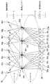
以下、本発明における実施の形態を図面に基づいて説明する。図1は本発明の実施の形態に係る遠隔監視システムの概略を示し、図2は前記遠隔監視システムの接続状態の例を示し、図3は遠隔監視システムの各部分の詳細を示す。
【0012】
図1において、遠隔監視システム10は、複数の被監視箇所の監視装置20、監視装置20から監視情報を受信する複数の監視センター30および複数の監視センター30から警報信号を受取る複数の管轄事業所40を備えている。
監視装置20、監視センター30および管轄事業所40は、専用回線、インターネット等のネットワーク(通信回線網)50により接続されている。ネットワーク50における情報伝達は、矢印付きの破線で示す。
例えば、監視装置20は、第1〜第12監視装置20a〜20mに区分され、監視センター30は、第1〜第4監視センター30a〜30dに区分され、管轄事業所40は、第1管轄事業所40a〜第8管轄事業所40hを備えている。
監視センター30は、被監視箇所の数に応じて数箇所設置され、この例では監視センター30は4箇所に設置されている。また、管轄事業所40は、被監視箇所の管理を考慮した適数設置されている。
ネットワーク50内のIPアドレスは、グループ化(グルーピング)処理を考慮して割り付けられ、これにより仮想の遠隔監視システム用ネットワークが構成される。
【0013】
図2に示すように、クライアントの受電設備、機器等の複数の被監視箇所は、例えば第1〜第8の管轄事業所(40a〜40h)ごとに管理するグループに区分してあり、第1〜第12監視装置(20a〜20m)は監視情報をネットワーク50を介して各監視センター(30a〜30d)に出力する。ここで、監視装置20a〜20c(第1グループ)、監視装置20d〜20f(第2グループ)、監視装置20g〜20i(第3グループ)、および監視装置20j〜20m(第4グループ)の監視情報の送付先は、それぞれ第1監視センター30a、第2監視センター30b、第3監視センター30c、第4監視センター30dである。
【0014】
なお、前記各監視装置20a〜20mは、図3に示すように、通信手段21、監視手段22、グループ情報(グルーピング情報)付加手段23、異常検出手段24、異常信号自動通報手段25およびデータ保存手段26を備えている。
通信手段21は監視装置20がネットワーク50を介して監視センター30と監視情報等の通信をするための手段である。監視手段22は被監視箇所を監視するセンサー、撮像手段、録音手段、故障表示の検出手段等を備え、監視情報を出力する。ここで、前記センサーは、電気機器、機械等の電流・電圧、消費電力、絶縁、漏電、温度、位置、圧力等を検知するものである。また、前記絶縁の検知は、例えば6000ボルトの高圧配電線のコロナ放電が発生する超音波を検知することにより行われる。
グループ情報付加手段23は前記監視情報に被監視箇所が属するグループを識別する情報を付加する手段である。ここで、「グループを識別する情報」は、例えば監視装置(20a等)ごとに地域別・組織別などに分類できる分類コードであり、その伝送先・伝送経路などは、IPアドレスと組み合わせて、複数の伝送先・伝送経路(バックアップ経路を含む。)を設定することができる。
【0015】
異常検出手段24は前記監視情報に被監視箇所の異常状態を検出して異常信号を異常信号自動通報手段25に出力する。なお、異常検出手段24は、前記監視情報がしきい値を超えたことを検出した場合、前記故障表示を検知した場合等を異常状態とする。異常信号自動通報手段25は、前記異常信号を自動的に監視センター30に出力する。データ保存手段26は、前記監視情報、異常信号等を記録する手段である。
【0016】
監視センター30(図1の30a等)は、図3に示すように、通信手段31、32、データ管理手段33、異常グループ判別手段34、異常データ保存手段35、警報信号発生手段36およびデータ収集手段37を備えている。
通信手段31、32は、それぞれネットワーク50を介して監視装置20、管轄事業所40と通信する手段である。データ管理手段33は、監視センター30が監視装置20から受信(収集)した監視情報を整理して記録し、さらに、前記監視情報の月報、年報等を編集することができる。異常グループ判別手段34は、異常信号等に付加されたグループ情報から被監視箇所のグループを判別する手段である。ここで、異常グループの判別は、異常信号に付加されたグルーピング情報を解析し、グルーピングテーブルを参照して、基本となる管轄事業所を判定(選択)する。また、異常グループ判別手段34は、グル―ピングテーブルを参照して、現在時点のグループ構成をチェックし、監視情報のグループ化を行い、グループ内管轄事業所から要求があれば、監視情報データを送信できるようにする。
【0017】
異常データ保存手段35は前記異常信号に含まれる被監視箇所の異常データを保存する手段である。警報信号発生手段36は、異常信号を監視装置20から受信したときに、グル―ピングテーブルを参照して、前記異常信号に付加されたグループ情報から判別されたグループを管轄するものとして選択された管轄事業所40に対して警報信号を送信する手段である。
なお、管轄事業所(40a等)の技術サービス員は、グル―ピングテーブルにおけるグルーピングの設定・変更として、基本管轄事業所(40a等)および権限付与された管轄事業所(40a等)の変更が可能であり、監視データ収集と同等の方法でグループ監視手段43の設定・変更の画面を要求表示することにより行うことができる。また、このグルーピング機能により、夜間・休日・台風等の非常時に対応して、管轄事業所(40a等)と受け持ち被監視箇所との組合わせや規模などを随時変更できる。
なお、グルーピングテーブルにおいて、監視情報の前記グループ間リンク構成をして、監視情報データのグループ間におけるアクセスの許可をすることもできる。
【0018】
また、正規情報伝達先の監視センター(30a等)およびネットワーク50の異常時には、伝送経路の変更・他監視センター(30a等)による業務代行などを行い、監視システムの系統構成をダイナミックに変更することができる。
データ収集手段37は、定期的に(例えば1日1回)監視装置20のデータ保存手段26からネットワーク50を介して監視情報・異常信号のデータを収集して保存する。
【0019】
管轄事業所40(図1の40a等)は、図3に示すように、通信手段41、警報信号受信手段42およびグループ監視手段43を備えている。
通信手段41はネットワーク50を介して監視センター30と通信する手段である。警報信号受信手段42は監視センター30が出力する警報信号を受信する手段であり、例えば被監視箇所の各グループにて異常が発生したことを表すパイロットランプを備えている。グループ監視手段43は、管轄する被監視箇所のグループを監視する手段である。
【0020】
図2に示すように、「レイヤー1」のモニタリング層(現地センサー監視層)、「レイヤー2」のスーパーパイザー層(遠隔監視層)および「レイヤー3」のユーザーレスポンス層(サービス応動層)が階層的に構成され、各ノードすなわち監視装置20、監視センター30および管轄事業所40は、自律分散的に監視制御情報を伝送する自律分散システムを構成している。また、前記各ノードは増加、変更が容易である。すなわち、各ノードの成長が可能である。
【0021】
各グループ(図1の監視装置20のグループに相当する)に区分された被監視箇所の監視装置20から発信する監視情報に付加したグループ情報と各監視センター30a、30b、30c、30dの設定をもとに通常時、夜間・休日、非常時、監視センター(30a等)の故障などに応じて監視システム系統を構成する。例えば、二点鎖線で示すように、各管轄事業所(40a〜40h)の代行や複数の監視センター30a〜30dによるバックアックルートを形成しておいて、休日等では、被監視箇所の特定のグループを監視センター30aで管理し、監視センター30bを休止させることもできる。
【0022】
さらに、図1に示すように、通常の管轄事業所40と併行して、クライアント(客)自身が各地に分散する被監視箇所としての系列店設備の監視装置(例えば20f、20g、20h)の一括管理をする管轄事業所40の一種としてクライアントの集中管理箇所60を設置することもできる。
【0023】
以上の構成により、遠隔監視システム10は、以下の動作をすることができる。図4および図5は遠隔監視システム10の動作を示すフローチャートである。図4に示すように、複数の被監視箇所ごとに設けられた監視手段22が各被監視箇所を監視し(S1)、異常検出手段24が監視情報の異常を検出すると(S2)、グループ情報付加手段23によりグループ情報が監視情報に付与され(S4)、異常信号自動通報手段25により異常信号が通信手段21およびネットワーク50を経て自動的に監視センター30に通報される(S5)。さらに、異常が検出された監視情報データはデータ保存手段26に保存される(S3)。
【0024】
つぎに、監視センター30では、前記異常信号が受信され(S6)、受信した異常信号から異常グループ判別手段34により被監視箇所の異常グループが判別され(S7)、異常データが異常データ保存手段35に保存される(S8)。さらに、警報信号発生手段36により異常グループを管轄するものとして選別された管轄事業所40に対して警報信号が作成通報される(S9)。
【0025】
つぎに、管轄事業所40では、警報信号受信手段42が警報信号を受信し(S10)、受信した警報信号を基にして被監視箇所の異常発生を表示する(S11)。
【0026】
なお、図5に示すように、管轄事業所40に駐在している技術サービス員が、異常信号の詳細情報を入手したいときは、グループ監視手段43を操作して監視情報データを要求すると(S21)、監視センター30は前記要求を受信し(S22)、要求された監視情報データの有り無しを判別する(S23)。異常データ保存手段35が要求された監視情報データを保持しているときは、その監視情報データを使用し、要求された監視情報データが異常データ保存手段35にないときは、監視センター30は被監視箇所の監視装置20のデータ保存手段26から監視情報データを収集する(S24)。このようにして、監視センター30は要求された監視情報データを管轄事業所40に送信する(S25)。そして、管轄事業所40は受信した監視情報データを表示する(S26)。
【0027】
また、前記各ノードの新増設等の変化に対しては、関係するレイヤー分のみのシステムデータ変更で対応でき、また、異なるメーカーや新方式のセンサー等で下位レイヤーの方式が既設のレイヤーの方式と異なる場合でも、下位レイヤーのみ新方式を採用し、上位レイヤーの方式を既設のレイヤーの処理方式と合わせることにより対応することができる。さらに、遠隔監視システム10の構成の変化・成長に対する自由度が高く、新しいサービスに対する柔軟性が高くなる。また、監視情報データの管理や遠隔監視システム10の保守の集中化が可能であり、効率的となる。
【0028】
また、上位ノードが下位レイヤーより自動通知される監視情報は、上位ノードの行動決定に必要な最小限のものとし、他は必要に応じて上位ノードが自ら随意および定周期に収集し、通信の効率化を図ることができる。
【0029】
監視センター30は、図2の「レイヤー2」にて得た被監視箇所からの監視情報をもとにその被監視箇所を管轄する管轄事業所40を判定し、監視情報をもとに管轄事業所40に駐在している技術サービス員の行動の指針となる必要最小限の情報にパターン化して管轄事業所40の警報信号受信手段42に通知する。このパターンの内容は以下のa〜dのとおりである。
a.現地出向など即対応が必要なもの
b.一定時間内に処理するもの
c.状態の把握だけしておくもの
d.他の管轄事業所管内の被監視箇所に関するもの
技術サービス員は、警報信号受信手段42が表示する情報をもとに判断し、必要な詳細情報を監視センター30から収集することができる。
【0030】
IPネットワーク提供者は、グループ処理に適したプライベートIPアドレスの割付等を行って遠隔監視システム10の各ノード間の確実な情報伝送を行う仮想の専用監視システムネットワークを構築して提供することができる。
【0031】
また、数万箇所以上のクライアントの受電設備や機器等を監視する広域かつ大規模の遠隔監視システム10をIP(インターネットプロトコル)ネットワークを活用して効率的に実現することができる。
さらに、IP接続ネットワークを使用して、ダイアルアップ接続時間の問題を解決し、汎用性、拡張性に優れたインターネット技術を適用することができる。
【0032】
なお、上記実施の形態において、複数の被監視箇所に対して、複数の監視センターおよび管轄事業所が設定されているが、実施例に示されたものに限定されず、被監視箇所、監視センターおよび管轄事業所の数は、必要に応じて変えることができる。
【0033】
【発明の効果】
請求項1記載の発明によれば、前記警報情報を受信した管轄事業所が自己の管轄グループの被監視箇所を監視センターを介して遠隔監視することができる。このため、被監視箇所を効率よく遠隔監視することができ、被監視箇所の変更・増加等に容易に対応できる。
さらに、請求項2記載の発明は、上記請求項1記載の発明の効果とともに、管轄事業所は、前記自己の管轄グループで異常が発生したことを容易に知ることができる。
さらに、請求項3記載の発明は、上記請求項2記載の発明の効果とともに、管轄事業所は、異常が生じている被監視箇所およびその異常内容を容易に特定することができる。
さらに、請求項4記載の発明は、上記請求項1記載の発明の効果とともに、管轄事業所は、被監視箇所の監視情報を随時入手することができる。
【図面の簡単な説明】
【図1】本発明の実施の形態に係る遠隔監視システムの概略を示すブロック図である。
【図2】前記遠隔監視システムの接続状態の例を示す説明図である。
【図3】前記遠隔監視システムの各部分の詳細を示すブロック図である。
【図4】前記遠隔監視システムの動作を示すフローチャートである。
【図5】図4と同様に、前記遠隔監視システムの動作を示すフローチャートである。
【図6】従来の遠隔監視システムを示す説明図である。
【符号の説明】
10 遠隔監視システム
20、20a〜20m 監視装置
21 通信手段
22 監視手段
23 グループ情報付加手段
24 異常検出手段
25 異常信号自動通報手段
30、30a〜30d 監視センター
31、32 通信手段
33 データ管理手段
34 異常グループ判別手段
36 警報信号発生手段
40、40a〜40h 管轄事業所
41 通信手段
42 警報信号受信手段
43 グループ監視手段
50 ネットワーク[0001]
TECHNICAL FIELD OF THE INVENTION
The present invention relates to a remote monitoring system for monitoring a number of monitored sites such as a large number of power receiving facilities and electrical devices, and more particularly to a remote monitoring system capable of efficiently monitoring a large number of monitored sites.
[0002]
[Prior art]
Conventionally, in a remote monitoring system, a monitoring device is installed at a monitored location, and when a sensor of this monitoring device detects an abnormality, the monitoring information that notifies this abnormality is served as a monitoring center via a public telephone line etc. Is reported to the remote monitoring device at the site. In the jurisdiction, the monitoring information received from the monitoring device is recorded, and personnel are dispatched to a monitored location where an abnormality has occurred (for example, see Patent Document 1).
For example, as shown in FIG. 6, when monitoring a large number of monitored
[0003]
[Patent Document 1]
JP-A-2002-112243 (page 2)
[0004]
[Problems to be solved by the invention]
However, in the above-described conventional example, when the number of monitored
[0005]
Further, in order to cope with the trouble of the monitoring system, it is necessary to arrange a system engineer having a high technical level as a technical service person for each of the
[0006]
Therefore, the problem to be solved by the present invention is to provide a remote monitoring system that can efficiently monitor a monitored location such as a large number of power receiving facilities and electrical devices, and can easily respond to changes and increases in the monitored location. To provide.
[0007]
[Means for Solving the Problems]
In order to solve the above-mentioned problem, an invention according to claim 1 is a remote monitoring system for remotely monitoring a plurality of monitored locations, wherein the plurality of monitored locations are divided into a plurality of groups, A monitoring device that monitors the monitored location and outputs monitoring information that is divided into the plurality of groups, and receives the monitoring information that is divided into the plurality of groups via a network, and At least one monitoring center that outputs an alarm signal for each monitored location divided into groups, and a plurality of jurisdiction establishments provided corresponding to the group of monitored locations, wherein each of the jurisdiction establishments Is a remote monitoring system characterized by receiving, via a network, the alarm signal for each group of the monitored locations controlled by the respective offices.
As a result, the plurality of monitored locations are divided into a plurality of groups, and a monitoring device arranged for each monitored location monitors each monitored location and outputs monitoring information, and the monitoring information is output to at least one location. The monitoring center receives the information via the network and outputs alarm information. A jurisdiction office that has jurisdiction over the group of monitored locations receives this alarm information via a network. For this reason, the jurisdiction office that has received the alarm information can remotely monitor the monitored location in the jurisdiction group.
[0008]
Further, according to a second aspect of the present invention, in the first aspect of the invention, the monitoring device monitors the monitored location and outputs a monitoring signal, and the monitoring device outputs the monitoring signal as the monitoring information for each monitored location. Abnormal signal notification means for notifying the abnormal signal to which the information of the group is added when the monitoring signal is abnormal, wherein the monitoring center receives the abnormal signal to which the information of the group is added, Selecting a jurisdictional office that has jurisdiction over the group of the monitored location indicated by the abnormal signal based on the information of the added group, and reporting an alarm signal indicating that the abnormality has occurred to the selected jurisdictional office. Is a remote monitoring system.
Thus, when the monitoring signal of the monitored location output by the sensor of the monitoring device is abnormal, the abnormal signal reporting unit reports the abnormal signal to which the group information of the monitored location is added, and reports the abnormal signal. The monitoring center receives and sends an alert signal to the business office selected based on the group information. For this reason, the selected jurisdiction office can know that an abnormality has occurred in the monitored location in the group under its jurisdiction.
[0009]
Further, in the invention according to
Thus, the selected jurisdiction office collects the abnormal signal data of the monitored location from the monitoring center by the group monitoring means, and specifies the monitored location where the abnormality has occurred and the content of the abnormality. it can.
[0010]
Further, in the invention according to claim 4, in the invention according to claim 1, the monitoring center includes data management means for organizing and recording the monitoring information. The monitoring information of the monitored location stored in the data management means of the monitoring center can be browsed via a network. As a result, the office in charge can obtain the monitoring information arranged and recorded by the data management means of the monitoring center at any time.
[0011]
BEST MODE FOR CARRYING OUT THE INVENTION
Hereinafter, embodiments of the present invention will be described with reference to the drawings. FIG. 1 shows an outline of a remote monitoring system according to an embodiment of the present invention, FIG. 2 shows an example of a connection state of the remote monitoring system, and FIG. 3 shows details of each part of the remote monitoring system.
[0012]
In FIG. 1, a
The
For example, the
The monitoring centers 30 are installed at several places according to the number of monitored places. In this example, the monitoring centers 30 are installed at four places. In addition, an appropriate number of
The IP addresses in the
[0013]
As shown in FIG. 2, a plurality of monitored locations such as power receiving equipment and devices of the client are divided into groups to be managed for each of the first to eighth business establishments (40a to 40h). The twelfth monitoring devices (20a to 20m) output monitoring information to the respective monitoring centers (30a to 30d) via the
[0014]
As shown in FIG. 3, each of the
The
The group
[0015]
The abnormality detecting means 24 detects an abnormal state of the monitored location in the monitoring information and outputs an abnormal signal to the abnormal signal automatic notifying
[0016]
As shown in FIG. 3, the monitoring center 30 (such as 30a in FIG. 1) includes communication means 31, 32, data management means 33, abnormal group discriminating means 34, abnormal data storing means 35, alarm signal generating means 36, and data collection. Means 37 are provided.
The communication means 31 and 32 are means for communicating with the
[0017]
The abnormal
In addition, as for the technical service staff of the jurisdiction office (40a etc.), as the setting / change of the grouping in the grouping table, the change of the basic jurisdiction office (40a etc.) and the authorized jurisdiction office (40a etc.) are required. It is possible to do so by requesting and displaying a setting / change screen of the group monitoring means 43 in the same manner as monitoring data collection. In addition, the grouping function can change the combination or scale of the jurisdiction office (40a or the like) and the monitored location at any time in response to an emergency such as night, holiday, or typhoon.
In the grouping table, the inter-group link of the monitoring information may be configured to permit access between the monitoring information data groups.
[0018]
In addition, when the monitoring center (30a or the like) to which the legitimate information is to be transmitted and the
The
[0019]
The jurisdiction 40 (such as 40a in FIG. 1) includes a
The communication means 41 is means for communicating with the
[0020]
As shown in Fig. 2, the monitoring layer of "Layer 1" (local sensor monitoring layer), the super-piser layer of "
[0021]
The group information added to the monitoring information transmitted from the
[0022]
Further, as shown in FIG. 1, in parallel with the
[0023]
With the above configuration, the
[0024]
Next, in the
[0025]
Next, in the
[0026]
As shown in FIG. 5, when a technical service representative stationed at the
[0027]
Also, changes such as new addition of each node can be handled by changing the system data only for the layer concerned, and the lower layer method is the same as the existing layer method for different manufacturers or sensors of the new method. Even if it is different from the above, it can be dealt with by adopting the new method only for the lower layer and matching the method of the upper layer with the processing method of the existing layer. Further, the degree of freedom for change and growth of the configuration of the
[0028]
Also, the monitoring information automatically notified by the upper layer from the lower layer shall be the minimum necessary for deciding the action of the upper node, and the other nodes shall collect the information at their own discretion and at regular intervals as necessary, and Efficiency can be improved.
[0029]
The
a. Items requiring immediate response, such as on-site dispatch b. Processing within a certain time c. Things to keep track of d. A technical service representative relating to a monitored location in another jurisdiction can determine based on the information displayed by the alarm signal receiving means 42 and collect necessary detailed information from the
[0030]
The IP network provider can construct and provide a virtual dedicated monitoring system network that performs reliable information transmission between the nodes of the
[0031]
In addition, a wide-area and large-scale
Furthermore, the problem of dial-up connection time can be solved by using the IP connection network, and Internet technology with excellent versatility and expandability can be applied.
[0032]
In the above embodiment, a plurality of monitoring centers and business establishments are set for a plurality of monitored locations. However, the present invention is not limited to those shown in the embodiment. And the number of jurisdictions can vary as needed.
[0033]
【The invention's effect】
According to the first aspect of the present invention, the jurisdiction office that has received the alarm information can remotely monitor the monitored location of its own jurisdiction group via the monitoring center. For this reason, the monitored location can be remotely monitored efficiently, and the monitored location can be easily changed or increased.
Further, according to the invention of
Further, according to the third aspect of the present invention, together with the effect of the second aspect of the present invention, the responsible office can easily specify the monitored location where the abnormality has occurred and the content of the abnormality.
Further, according to the invention described in claim 4, together with the effect of the invention described in claim 1, the jurisdiction office can obtain monitoring information of the monitored location at any time.
[Brief description of the drawings]
FIG. 1 is a block diagram schematically showing a remote monitoring system according to an embodiment of the present invention.
FIG. 2 is an explanatory diagram showing an example of a connection state of the remote monitoring system.
FIG. 3 is a block diagram showing details of each part of the remote monitoring system.
FIG. 4 is a flowchart showing an operation of the remote monitoring system.
FIG. 5 is a flowchart showing the operation of the remote monitoring system, similarly to FIG. 4;
FIG. 6 is an explanatory diagram showing a conventional remote monitoring system.
[Explanation of symbols]
Claims (4)
前記複数の被監視箇所は複数のグループに区分されており、
前記被監視箇所ごとに設けられ、前記被監視箇所を監視して、前記複数のグループに区分された監視情報を出力する監視装置と、
前記複数のグループに区分された監視情報をネットワーク経由で受信して前記複数のグループに区分された被監視箇所ごとの警報信号を出力する少なくとも1箇所の監視センターと、
前記被監視箇所のグループに対応して設けられた複数の管轄事業所とを備え、前記各管轄事業所は前記各管轄事業所が管轄する前記被監視箇所のグループごとの前記警報信号をネットワーク経由で受信することを特徴とする遠隔監視システム。In a remote monitoring system for remotely monitoring a plurality of monitored locations,
The plurality of monitored locations are divided into a plurality of groups,
A monitoring device that is provided for each monitored location, monitors the monitored location, and outputs monitoring information divided into the plurality of groups;
At least one monitoring center that receives the monitoring information divided into the plurality of groups via a network and outputs an alarm signal for each monitored part divided into the plurality of groups;
A plurality of jurisdictional offices provided corresponding to the group of monitored sites, wherein each of the jurisdictional offices transmits the alarm signal for each group of the monitored sites controlled by each of the monitored offices via a network. A remote monitoring system characterized by receiving at a remote location.
前記監視装置は、前記被監視箇所を監視して監視信号を出力するセンサーと、前記被監視箇所ごとの監視情報として前記センサーの監視信号が異常なときに、前記グループの情報が付加された異常信号を通報する異常信号通報手段とを備え、
前記監視センターは、前記グループの情報が付加された異常信号を受信し、前記付加されたグループの情報により前記異常信号が示す被監視箇所のグループを管轄する管轄事業所を選択し、選択された管轄事業所に前記異常が発生したことを示す警報信号を通報することを特徴とする遠隔監視システム。The remote monitoring system according to claim 1, wherein
The monitoring device is a sensor that monitors the monitored location and outputs a monitoring signal. The monitoring device monitors the monitored location and outputs a monitoring signal for each monitored location. Abnormal signal reporting means for reporting a signal,
The monitoring center receives the abnormal signal to which the information of the group has been added, and selects a jurisdiction office that has jurisdiction over the group of the monitored part indicated by the abnormal signal according to the information of the added group, and is selected. A remote monitoring system for notifying a responsible office of an alarm signal indicating that the abnormality has occurred.
前記管轄事業所は前記管轄するグループの被監視箇所を監視するグループ監視手段を備え、
前記警報信号を受信した管轄事業所は、そのグループ監視手段によりネットワークを経由して前記監視センターから前記異常信号のデータを収集することを特徴とする遠隔監視システム。The remote monitoring system according to claim 2, wherein
The jurisdiction has group monitoring means for monitoring a monitored location of the group under the jurisdiction,
The remote monitoring system, wherein the jurisdiction office receiving the alarm signal collects the data of the abnormal signal from the monitoring center via a network by the group monitoring means.
前記監視センターは前記監視情報を整理して記録するデータ管理手段を備え、前記管轄事業所のグループ監視手段は、随時にネットワークを介して前記監視センターのデータ管理手段に保存されている被監視箇所の監視情報を閲覧できることを特徴とする遠隔監視システム。The remote monitoring system according to claim 1, wherein
The monitoring center includes a data management unit that organizes and records the monitoring information, and the group monitoring unit of the jurisdiction of the business office monitors a monitored location stored in the data management unit of the monitoring center via a network as needed. A remote monitoring system capable of browsing monitoring information of a remote controller.
Priority Applications (1)
| Application Number | Priority Date | Filing Date | Title |
|---|---|---|---|
| JP2002370571A JP2004199617A (en) | 2002-12-20 | 2002-12-20 | Remote monitoring system |
Applications Claiming Priority (1)
| Application Number | Priority Date | Filing Date | Title |
|---|---|---|---|
| JP2002370571A JP2004199617A (en) | 2002-12-20 | 2002-12-20 | Remote monitoring system |
Publications (1)
| Publication Number | Publication Date |
|---|---|
| JP2004199617A true JP2004199617A (en) | 2004-07-15 |
Family
ID=32766453
Family Applications (1)
| Application Number | Title | Priority Date | Filing Date |
|---|---|---|---|
| JP2002370571A Pending JP2004199617A (en) | 2002-12-20 | 2002-12-20 | Remote monitoring system |
Country Status (1)
| Country | Link |
|---|---|
| JP (1) | JP2004199617A (en) |
Cited By (2)
| Publication number | Priority date | Publication date | Assignee | Title |
|---|---|---|---|---|
| JP2006260045A (en) * | 2005-03-16 | 2006-09-28 | Hitachi Building Systems Co Ltd | Entrance / exit management system |
| JP2010224662A (en) * | 2009-03-19 | 2010-10-07 | Secom Co Ltd | Abnormality reporting system |
-
2002
- 2002-12-20 JP JP2002370571A patent/JP2004199617A/en active Pending
Cited By (2)
| Publication number | Priority date | Publication date | Assignee | Title |
|---|---|---|---|---|
| JP2006260045A (en) * | 2005-03-16 | 2006-09-28 | Hitachi Building Systems Co Ltd | Entrance / exit management system |
| JP2010224662A (en) * | 2009-03-19 | 2010-10-07 | Secom Co Ltd | Abnormality reporting system |
Similar Documents
| Publication | Publication Date | Title |
|---|---|---|
| EP1257089B1 (en) | Method and system for generating geographic visual displays of broadband network data | |
| EP1279253A2 (en) | Geographic network management system | |
| KR100867864B1 (en) | Ubiquitous Sensor Network Integrated Control System and Method | |
| KR101186774B1 (en) | Unified control system for ubiquitous city | |
| JP2001141290A (en) | Air conditioner and its monitoring device | |
| JP2004199617A (en) | Remote monitoring system | |
| KR100211937B1 (en) | Remote controller supervision apparatus | |
| JP2007114907A (en) | Equipment information monitoring and maintenance support system | |
| KR100272006B1 (en) | Method and apparatus for managing alarm/overflow traffic data of exchange centrally | |
| JP2024083124A (en) | POWER RECEIVING AND TRANSFORMING EQUIPMENT SECURITY SYSTEM, POWER RECEIVING AND TRANSFORMING EQUIPMENT SECURITY METHOD, SMART GATEWAY AND PROGRAM | |
| JP2005031820A (en) | Remote monitoring system and remote monitoring method | |
| JP3445863B2 (en) | Building group remote management device | |
| CN102540996B (en) | Remote energy metering and monitoring system for chain operation enterprise | |
| JP2003221845A (en) | Remote management system for water and sewage facilities | |
| JP4616696B2 (en) | Elevator control operation information collection device | |
| US10608909B2 (en) | Network data aggregation system and method for building management systems | |
| JP2001177657A (en) | Data collection system using telephone line | |
| JPH11348788A (en) | Signal facility control device | |
| JP4965239B2 (en) | Remote monitoring system | |
| JP2002055714A (en) | Maintenance management system | |
| KR100853521B1 (en) | Optical network management system and management method of video optical transmission device | |
| KR101651063B1 (en) | Apparatus and Method for Remote Monitoring Based on the Recognizing Position using Smart Device | |
| JP4909172B2 (en) | Alarm information remote notification device and alarm information remote notification system | |
| JP2004145624A (en) | Disaster prevention system | |
| JPH10135950A (en) | Network management system |
Legal Events
| Date | Code | Title | Description |
|---|---|---|---|
| A977 | Report on retrieval |
Free format text: JAPANESE INTERMEDIATE CODE: A971007 Effective date: 20050926 |
|
| A131 | Notification of reasons for refusal |
Free format text: JAPANESE INTERMEDIATE CODE: A131 Effective date: 20051004 |
|
| A521 | Written amendment |
Free format text: JAPANESE INTERMEDIATE CODE: A523 Effective date: 20051130 |
|
| A02 | Decision of refusal |
Free format text: JAPANESE INTERMEDIATE CODE: A02 Effective date: 20060117 |