JP2004200726A - Substrate processing equipment - Google Patents

Substrate processing equipment Download PDF

Info

Publication number
JP2004200726A
JP2004200726A JP2004092101A JP2004092101A JP2004200726A JP 2004200726 A JP2004200726 A JP 2004200726A JP 2004092101 A JP2004092101 A JP 2004092101A JP 2004092101 A JP2004092101 A JP 2004092101A JP 2004200726 A JP2004200726 A JP 2004200726A
Authority
JP
Japan
Prior art keywords
substrate
unit
processing
transfer
transfer robot
Prior art date
Legal status (The legal status is an assumption and is not a legal conclusion. Google has not performed a legal analysis and makes no representation as to the accuracy of the status listed.)
Granted
Application number
JP2004092101A
Other languages
Japanese (ja)
Other versions
JP4027334B2 (en
Inventor
Joichi Nishimura
讓一 西村
Masami Otani
正美 大谷
Current Assignee (The listed assignees may be inaccurate. Google has not performed a legal analysis and makes no representation or warranty as to the accuracy of the list.)
Dainippon Screen Manufacturing Co Ltd
Original Assignee
Dainippon Screen Manufacturing Co Ltd
Priority date (The priority date is an assumption and is not a legal conclusion. Google has not performed a legal analysis and makes no representation as to the accuracy of the date listed.)
Filing date
Publication date
Application filed by Dainippon Screen Manufacturing Co Ltd filed Critical Dainippon Screen Manufacturing Co Ltd
Priority to JP2004092101A priority Critical patent/JP4027334B2/en
Publication of JP2004200726A publication Critical patent/JP2004200726A/en
Application granted granted Critical
Publication of JP4027334B2 publication Critical patent/JP4027334B2/en
Anticipated expiration legal-status Critical
Expired - Fee Related legal-status Critical Current

Links

Images

Landscapes

  • Container, Conveyance, Adherence, Positioning, Of Wafer (AREA)
  • Exposure Of Semiconductors, Excluding Electron Or Ion Beam Exposure (AREA)

Abstract

【課題】 作業者の負担を軽減し、基板の汚染や破損などを軽減して所定の検査が行える基板処理装置を提供する。
【解決手段】 現像処理で得られたパターンに関する所定の検査を行う検査装置4が、インデクサ部70の受渡し用搬送路71の端部に配置されている。基板処理部80で現像処理された基板は、処理部用基板搬送ロボット81から、受渡し用搬送路71に設けられた受渡し用基板搬送ロボット73に渡される。受渡し用基板搬送ロボット73はその基板を検査装置4に渡す。検査を終えた基板は受渡し用基板搬送ロボット73によってカセット74に収納される。
【選択図】 図6
PROBLEM TO BE SOLVED: To provide a substrate processing apparatus capable of performing a predetermined inspection while reducing a burden on an operator and reducing contamination and breakage of a substrate.
An inspection device (4) for performing a predetermined inspection on a pattern obtained by a developing process is disposed at an end of a transfer path (71) for delivery of an indexer unit (70). The substrate developed by the substrate processing unit 80 is transferred from the processing unit substrate transfer robot 81 to the transfer substrate transfer robot 73 provided in the transfer transfer path 71. The transfer substrate transfer robot 73 transfers the substrate to the inspection device 4. The substrate after the inspection is stored in the cassette 74 by the transfer substrate transfer robot 73.
[Selection] Fig. 6

Description

本発明は、フォトリソグラフィ工程の少なくとも現像処理と熱処理とを行う基板処理装置に関する。   The present invention relates to a substrate processing apparatus that performs at least a development process and a heat treatment in a photolithography process.

フォトリソグラフィ工程の一連の処理は、露光処理前後の各種のレジスト処理を行う基板処理装置と露光処理を行う露光装置により行われている。このフォトリソグラフィ工程では、現像処理を終えた基板の表面に多段に重ね合わせて形成された上下のパターンの重ね合わせ位置精度や、形成されたパターンの線幅精度など現像処理で得られたパターンに関する所定の検査を行う場合がある。この検査は、従来、現像処理を終えた基板を作業者が基板処理装置から取り出し、検査装置まで人手で運搬して、その検査装置に搬入して検査を実施している。また、検査後の基板を基板処理装置に戻す場合にも、検査を終えた基板を作業者が検査装置から取り出し、基板処理装置まで人手で運搬して、基板処理装置に戻すようにしている。   A series of processes in the photolithography process are performed by a substrate processing apparatus that performs various types of resist processing before and after the exposure processing and an exposure apparatus that performs the exposure processing. In this photolithography process, the pattern obtained by the development process, such as the overlay position accuracy of the upper and lower patterns formed in multiple stages on the surface of the substrate after the development process and the line width accuracy of the formed pattern, A predetermined inspection may be performed. In this inspection, conventionally, an operator takes out the substrate after the development processing from the substrate processing apparatus, transports the substrate manually to the inspection apparatus, and carries it into the inspection apparatus to perform the inspection. Also, when returning the inspected substrate to the substrate processing apparatus, the operator removes the inspected substrate from the inspection apparatus, transports the substrate to the substrate processing apparatus by hand, and returns the substrate to the substrate processing apparatus.

しかしながら、上述したように、基板処理装置や検査装置に対する基板の搬入、取り出しや、基板処理装置と検査装置との間の基板の運搬を人手で行っていると、作業者の負担になるし、さらに、基板を汚染したり、基板を落として破損したりする危険性が高いという問題がある。   However, as described above, loading and unloading the substrate into and out of the substrate processing apparatus and the inspection apparatus, and transporting the substrate between the substrate processing apparatus and the inspection apparatus by hand, burdens the operator, Further, there is a problem that there is a high risk of contaminating the substrate or dropping and damaging the substrate.

本発明は、このような事情に鑑みてなされたものであって、作業者の負担を軽減し、基板の汚染や破損などを軽減して所定の検査が行える基板処理装置を提供することを目的とする。  The present invention has been made in view of such circumstances, and an object of the present invention is to provide a substrate processing apparatus capable of reducing a burden on an operator, reducing contamination and breakage of a substrate, and performing a predetermined inspection. And

本発明は、このような目的を達成するために、次のような構成をとる。   The present invention has the following configuration to achieve such an object.

すなわち、請求項1に記載の発明に係る基板処理装置は、所定方向に延びた受渡し用搬送路と、前記受渡し用搬送路のその一方の側部側に配置されたカセット載置台と、前記受渡し用搬送路に設けられた受渡し用基板搬送ロボットとを含んだインデクサ部と、
露光処理で基板に焼き付けられたパターンを得る現像処理を行う現像処理ユニットと、熱処理を行う熱処理ユニットと、これらの処理ユニットに対して基板を搬送する処理部用基板搬送ロボットとを含み、前記インデクサ部の前記受渡し用搬送路の他方の側部側に配置された基板処理部と、
現像処理で得られたパターンに関する所定の検査を行う検査装置とを備え、
前記検査装置は、前記インデクサ部の前記受渡し用搬送路の端部に配置されていることを特徴とする。
That is, the substrate processing apparatus according to the first aspect of the present invention includes a delivery path extending in a predetermined direction, a cassette mounting table disposed on one side of the delivery path, An indexer unit including a transfer substrate transfer robot provided in a transfer path for
A developing unit for performing a developing process for obtaining a pattern printed on the substrate by the exposure process, a thermal processing unit for performing a thermal process, and a substrate transport robot for a processing unit configured to transport the substrate to these processing units; A substrate processing unit disposed on the other side of the transfer path for the unit,
An inspection device for performing a predetermined inspection on the pattern obtained by the development process,
The inspection device is arranged at an end of the delivery path of the indexer unit.

[作用]請求項1に記載の発明によれば、基板処理部において処理部用基板搬送ロボットが基板を現像処理ユニットおよび熱処理ユニットに搬送し、現像処理および熱処理が行われる。現像処理を終えた基板、または、現像処理後の熱処理を終えた基板は、処理部用基板搬送ロボットからインデクサ部の受渡し用基板搬送ロボットに渡される。受渡し用基板搬送ロボットは、受け取った基板を受渡し用搬送路の端部に配置されている検査装置に渡す。検査装置で所定の検査を受けた基板は受渡し用基板搬送ロボットによって、カセット載置台に置かれているカセットに収納される。   [Operation] According to the invention described in claim 1, in the substrate processing section, the processing section substrate transfer robot transfers the substrate to the development processing unit and the heat treatment unit, and the development processing and the heat treatment are performed. The substrate that has completed the development process or the substrate that has completed the heat treatment after the development process is transferred from the processing unit substrate transfer robot to the delivery substrate transfer robot of the indexer unit. The transfer substrate transfer robot transfers the received substrate to an inspection device arranged at an end of the transfer transfer path. The substrate that has undergone a predetermined inspection by the inspection device is stored in a cassette placed on a cassette mounting table by the transfer substrate transfer robot.

請求項2に記載の発明は、請求項1に記載の基板処理装置において、前記検査装置は、前記受渡し用基板搬送ロボットと直接に基板を受渡しすることを特徴とする。   According to a second aspect of the present invention, in the substrate processing apparatus according to the first aspect, the inspection apparatus transfers the substrate directly to the transfer substrate transfer robot.

[作用]請求項2記載の発明によれば、受渡し用基板搬送ロボットが検査装置との間で直接に基板の受け渡しを行う。   According to the second aspect of the present invention, the transfer substrate transfer robot directly transfers the substrate to and from the inspection apparatus.

請求項1記載の発明によれば、現像処理で得られたパターンに関する所定の検査を行う検査装置をインデクサ部の受渡し用搬送路の端部に配置し、検査装置に対する基板の受け渡しを受渡し用基板搬送ロボットで行うようにしたので、基板処理部と検査装置との間の基板の搬送を自動で行うことができ、作業者の負担を軽減できるとともに、基板の汚染や破損などの危険性を低減することができる。   According to the first aspect of the present invention, an inspection device for performing a predetermined inspection on the pattern obtained by the development processing is disposed at an end of the delivery path of the indexer unit, and the delivery of the substrate to the inspection device is performed by the delivery substrate. Because the transfer robot is used, the transfer of the substrate between the substrate processing unit and the inspection device can be performed automatically, reducing the burden on the operator and reducing the risk of contamination and breakage of the substrate. can do.

請求項2記載の発明によれば、受渡し用基板搬送ロボットが検査装置との間で直接に基板の受け渡しを行うので、IFユニットを省略して、受け渡し用搬送路に隣接して検査装置を配置することができる。   According to the second aspect of the present invention, since the transfer substrate transfer robot directly transfers the substrate to and from the inspection device, the IF unit is omitted and the inspection device is disposed adjacent to the transfer transfer path. can do.

以下、図面を参照して本発明の実施例を説明する。   Hereinafter, embodiments of the present invention will be described with reference to the drawings.

<参考例>
図1は本発明の参考例に係る基板処理装置及びその基板処理装置を含む基板処理システムの全体構成を示す平面図である。
<Reference example>
FIG. 1 is a plan view showing the entire configuration of a substrate processing apparatus according to a reference example of the present invention and a substrate processing system including the substrate processing apparatus.

この基板処理システムは、基板処理装置1と、露光装置2と、基板処理装置1と露光装置2との間で基板の受渡しを行う第1のインターフェイス(IF)ユニット3と、検査部に相当する検査装置4と、基板処理装置1と検査装置4との間で基板の受渡しを行う第2のインターフェイス(IF)ユニット5とを備えている。   This substrate processing system corresponds to a substrate processing apparatus 1, an exposure apparatus 2, a first interface (IF) unit 3 for transferring a substrate between the substrate processing apparatus 1 and the exposure apparatus 2, and an inspection unit. The inspection apparatus includes an inspection apparatus 4 and a second interface (IF) unit 5 for transferring a substrate between the substrate processing apparatus 1 and the inspection apparatus 4.

基板処理装置1は、ローダ部11と、各種の熱処理を行う第1〜第4の熱処理ユニット12〜15と、レジスト膜の塗布処理を行うレジスト塗布処理ユニット16と、現像処理を行う現像処理ユニット17と、コンベアなどで構成される基板搬送機構(図示せず)と、アンローダ部18とを備え、ローダ部11及びアンローダ部18と各処理ユニット12〜17とが2列構成に配置されている。   The substrate processing apparatus 1 includes a loader unit 11, first to fourth heat treatment units 12 to 15 for performing various heat treatments, a resist coating unit 16 for performing a resist film coating process, and a development processing unit for performing a development process. 17, a substrate transport mechanism (not shown) constituted by a conveyor or the like, and an unloader section 18. The loader section 11, the unloader section 18, and the processing units 12 to 17 are arranged in a two-row configuration. .

すなわち、第1列目には、図の左から順に、ローダ部11、第1の熱処理ユニット12、レジスト塗布処理ユニット16、第2の熱処理ユニット13が配置され、その第1列目のローダ部11及び各処理ユニット12、16、13に隣接させて第2列目には、図の右から順に、第3の熱処理ユニット14、現像処理ユニット17、第4の熱処理ユニット15、アンローダ部18が配置されている。   That is, in the first column, a loader unit 11, a first heat treatment unit 12, a resist coating unit 16 and a second heat treatment unit 13 are arranged in this order from the left in the figure. In the second row adjacent to the processing units 11, 12, 16, and 13, a third heat treatment unit 14, a development processing unit 17, a fourth heat treatment unit 15, and an unloader unit 18 are arranged in order from the right in the figure. Are located.

基板搬送機構は第1列目と第2列目とにそれぞれ設けられている。   The substrate transport mechanism is provided in each of the first and second rows.

第1列目に設けられた基板搬送機構は、図の矢印P1に示すように、ローダ部11から搬入された未処理の基板を第1の熱処理ユニット12、レジスト塗布処理ユニット16、第2の熱処理ユニット13の順に搬送していき、各処理ユニット12、16、13で露光処理前の各処理を行わせる。また、第2列目に設けられた基板搬送機構は、図の矢印P2に示すように、第1のIFユニット3から受け取った露光処理済の基板を第3の熱処理ユニット14、現像処理ユニット17、第4の熱処理ユニット15の順に搬送していき、各処理ユニット14、17、15で露光処理後の各処理を行わせ、フォトリソグラフィ工程の一連の処理を終えた基板をアンローダ部18から搬出させる。   The substrate transport mechanism provided in the first column converts the unprocessed substrate loaded from the loader unit 11 into the first heat treatment unit 12, the resist coating unit 16, the second substrate as shown by the arrow P1 in the figure. The wafers are conveyed in the order of the heat treatment unit 13, and the respective processing units 12, 16, and 13 perform each processing before the exposure processing. Further, the substrate transport mechanism provided in the second column, as shown by the arrow P2 in the drawing, converts the exposed substrate received from the first IF unit 3 into the third heat treatment unit 14, the development processing unit 17 and the like. Then, the substrate is transported in the order of the fourth heat treatment unit 15, each of the processing units 14, 17, and 15 is subjected to each processing after the exposure processing, and the substrate after the series of the photolithography process is unloaded from the unloader unit 18. Let it.

なお、第1〜第4の熱処理ユニット12〜15にはそれぞれ加熱処理ユニットと冷却処理ユニットとを備えていて、各熱処理ユニット12〜15では、加熱処理ユニットで所定の加熱処理を行った後、冷却処理ユニットで加熱された基板を所定温度まで冷却するように構成している。第1の熱処理ユニット12ではレジスト塗布処理前の熱処理(密着強化剤塗布処理(HMDS処理)など)を行い、第2の熱処理ユニット13ではレジスト塗布処理後の熱処理(ソフトベーク)を行い、第3の熱処理ユニット14では露光処理後の熱処理を行い、第4の熱処理ユニット15では現像処理後の熱処理(ハードベーク)を行う。   Each of the first to fourth heat treatment units 12 to 15 includes a heat treatment unit and a cooling treatment unit. In each of the heat treatment units 12 to 15, after performing a predetermined heat treatment in the heat treatment unit, The substrate heated by the cooling processing unit is cooled to a predetermined temperature. The first heat treatment unit 12 performs a heat treatment (such as an adhesion enhancer application process (HMDS treatment)) before the resist coating process, and the second heat treatment unit 13 performs a heat treatment (soft bake) after the resist coating process. In the heat treatment unit 14, heat treatment after exposure processing is performed, and in the fourth heat treatment unit 15, heat treatment (hard bake) after development processing is performed.

露光装置2には、ステッパーなどの露光機や、位置合わせ用のアライメント機構、露光装置2内の基板の搬送などを行う基板搬送ロボットなど(いずれも図示せず)を備えていて、基板表面に塗布されたレジスト膜に所定のパターンを焼き付ける露光処理を行うように構成されている。この露光装置2は、第1のIFユニット3を間に挟んで基板処理装置1の第2、第3の熱処理ユニット13、14の近くに配置されている。   The exposure apparatus 2 includes an exposure machine such as a stepper, an alignment mechanism for positioning, a substrate transport robot for transporting the substrate in the exposure apparatus 2, and the like (all not shown). An exposure process for printing a predetermined pattern on the applied resist film is performed. The exposure apparatus 2 is arranged near the second and third heat treatment units 13 and 14 of the substrate processing apparatus 1 with the first IF unit 3 interposed therebetween.

第1のIFユニット3は、一方の側面が基板処理装置1の第2、第3の熱処理ユニット13、14に隣接し、他方の側面が露光装置2に隣接して配置され、基板処理装置1の第2の熱処理ユニット13から基板を受け取って露光装置2に引き渡すとともに、露光装置2から受け取った露光処理済の基板を基板処理装置1の第3の熱処理ユニット14に引き渡すための露光装置間基板受渡し手段としての基板受渡しロボット31を備えている。   The first IF unit 3 has one side surface adjacent to the second and third heat treatment units 13 and 14 of the substrate processing apparatus 1 and the other side surface disposed adjacent to the exposure apparatus 2. A substrate between exposure apparatuses for receiving the substrate from the second heat treatment unit 13 and delivering the substrate to the exposure apparatus 2 and delivering the exposed substrate received from the exposure apparatus 2 to the third heat treatment unit 14 of the substrate processing apparatus 1 A substrate transfer robot 31 is provided as transfer means.

この基板受渡しロボット31は、基板を保持する基板保持アーム31aと、基板保持アーム31aを支持するアーム支持台31bとを備えている。基板保持アーム31aは、アーム支持台31bに対して水平方向(図1の紙面に平行な方向)に進退移動可能に構成されている。また、この参考例では、アーム支持台31bは、図1のY方向への往復移動(基板保持アーム31aの進退移動のY方向の位置の変更)や、鉛直方向(図1の紙面に垂直な方向)への昇降移動(基板保持アーム31aの高さ位置の変更)、鉛直方向の軸芯R1周りでの旋回(水平面内における基板保持アーム31aの進退移動方向の変更)などが可能に構成されている。   The substrate transfer robot 31 includes a substrate holding arm 31a that holds a substrate, and an arm support 31b that supports the substrate holding arm 31a. The substrate holding arm 31a is configured to be able to advance and retreat in a horizontal direction (a direction parallel to the plane of FIG. 1) with respect to the arm support base 31b. Further, in this reference example, the arm support base 31b is reciprocated in the Y direction in FIG. 1 (change of the position of the forward / backward movement of the substrate holding arm 31a in the Y direction) or in the vertical direction (perpendicular to the plane of FIG. 1). (Change of the height position of the substrate holding arm 31a), turning around the axis R1 in the vertical direction (change of the forward / backward movement direction of the substrate holding arm 31a in the horizontal plane), and the like. ing.

基板受渡しロボット31は、アーム支持台31bや基板保持アーム31aの各動作を適宜に組み合わせて、第2の熱処理ユニット13から露光装置2への基板の受渡しと、露光装置2から第3の熱処理ユニット14への基板の受渡しとを行うように構成されている。   The substrate transfer robot 31 combines the operations of the arm support table 31b and the substrate holding arm 31a as appropriate to transfer the substrate from the second heat treatment unit 13 to the exposure apparatus 2, and to transfer the substrate from the exposure apparatus 2 to the third heat treatment unit. 14 is provided.

なお、図では、基板受渡しロボット31を1台のみ図示しているが、2台以上の基板受渡しロボット31を第1のIFユニット3に備えて、これら複数台の基板受渡しロボット31が共働して、基板処理装置1と露光装置2との間の基板の受渡しを行うように構成してもよい。   Although only one substrate transfer robot 31 is shown in the drawing, two or more substrate transfer robots 31 are provided in the first IF unit 3 and the plurality of substrate transfer robots 31 cooperate. Thus, the transfer of the substrate between the substrate processing apparatus 1 and the exposure apparatus 2 may be performed.

また、第1のIFユニット3には、基板を一時的に保管するための基板保管部32を備えていて、基板処理装置1と露光装置2との間の基板の受渡しのタイミングにズレが生じたときに、この基板保管部32に基板を一時的に保管することでそのズレを吸収して、これら装置1、2間の基板の受渡しが停滞するのを防止するように構成されている。   Further, the first IF unit 3 is provided with a substrate storage unit 32 for temporarily storing the substrate, and the timing of the transfer of the substrate between the substrate processing apparatus 1 and the exposure apparatus 2 is shifted. In such a case, the gap is absorbed by temporarily storing the substrate in the substrate storage section 32 to prevent the transfer of the substrate between the devices 1 and 2 from being stagnated.

例えば、基板受渡しロボット31が第2の熱処理ユニット13から基板を受け取って露光装置2にその基板を引き渡そうとするとき、露光装置2側が基板の受け取りタイミングにない場合には、基板受渡しロボット31は第2の熱処理ユニット13から受け取った基板を基板保管部32に保管し、露光装置2側が基板の受け取りタイミングになると、基板受渡しロボット31は基板保管部32に保管した基板を取り出して露光装置2に引き渡す。また、基板受渡しロボット31が露光装置2から基板を受け取って第3の熱処理ユニット14にその基板を引き渡そうとするとき、第3の熱処理ユニット14側が基板の受け取りタイミングにない場合にも同様に、基板受渡しロボット31は露光装置2から受け取った基板を基板保管部32に保管し、第3の熱処理ユニット14側が基板の受け取りタイミングになると、基板受渡しロボット31は基板保管部32に保管した基板を取り出して第3の熱処理ユニット14に引き渡す。なお、基板処理装置1と露光装置2との間の基板の受渡しのタイミングのズレが大きい場合も考慮して、基板保管部32は受渡し待ちの複数枚の基板を同時に保管し得るように構成されている。   For example, when the substrate transfer robot 31 receives a substrate from the second heat treatment unit 13 and intends to deliver the substrate to the exposure apparatus 2, if the exposure apparatus 2 is not at the substrate reception timing, the substrate transfer robot 31 Stores the substrate received from the second heat treatment unit 13 in the substrate storage section 32, and when the exposure apparatus 2 side receives the substrate, the substrate transfer robot 31 takes out the substrate stored in the substrate storage section 32 and retrieves the exposure apparatus 2 Hand over to Similarly, when the substrate transfer robot 31 receives the substrate from the exposure apparatus 2 and intends to transfer the substrate to the third heat treatment unit 14, the third heat treatment unit 14 is not in the timing of receiving the substrate. The substrate transfer robot 31 stores the substrate received from the exposure apparatus 2 in the substrate storage unit 32, and when the third heat treatment unit 14 comes to receive the substrate, the substrate transfer robot 31 deletes the substrate stored in the substrate storage unit 32. It is taken out and delivered to the third heat treatment unit 14. Note that the substrate storage unit 32 is configured to simultaneously store a plurality of substrates waiting to be delivered in consideration of a case where the timing of delivery of the substrate between the substrate processing apparatus 1 and the exposure apparatus 2 is large. ing.

検査装置4は、従来の単体の検査装置と同様に、位置合わせ用のアライメント機構や、パターンの読み取りヘッドなどを含む適宜の検査機構、検査装置4内の基板の搬送などを行う基板搬送ロボットなど(いずれも図示せず)を備えていて、基板表面に多段に重ね合わせて形成された上下のパターンの重ね合わせ位置精度や、形成されたパターンの線幅精度など現像処理で得られたパターンに関する所定の検査を行うように構成されている。この検査装置4は、第2のIFユニット5を間に挟んで基板処理装置1の現像処理ユニット17の近くに配置されている。   The inspection apparatus 4 includes an alignment mechanism for positioning, an appropriate inspection mechanism including a pattern reading head and the like, a substrate transport robot that transports the substrate in the inspection apparatus 4, and the like, like the conventional single inspection apparatus. (Neither is shown), and relates to the pattern obtained by the developing process, such as the overlay position accuracy of the upper and lower patterns formed by multi-layering on the substrate surface and the line width accuracy of the formed pattern. It is configured to perform a predetermined inspection. The inspection device 4 is disposed near the development processing unit 17 of the substrate processing apparatus 1 with the second IF unit 5 interposed therebetween.

第2のIFユニット5は、一方の側面が基板処理装置1の現像処理ユニット17に隣接し、他方の側面が検査装置4に隣接して配置され、基板処理装置1内の現像処理ユニット17から基板を受け取って検査装置4に引き渡すとともに、検査装置4から受け取った検査済の基板を現像処理ユニット17に引き渡すための検査部間基板受渡し手段としての基板受渡しロボット51を備えている。   The second IF unit 5 has one side surface adjacent to the development processing unit 17 of the substrate processing apparatus 1 and the other side surface disposed adjacent to the inspection device 4. A substrate transfer robot 51 is provided as an inter-inspection unit substrate transfer unit for receiving and transferring the substrate to the inspection device 4 and transferring the inspected substrate received from the inspection device 4 to the development processing unit 17.

この基板受渡しロボット51は、基板を保持する基板保持アーム51aと、基板保持アーム51aを支持するアーム支持台51bとを備えている。基板保持アーム51aは、アーム支持台51bに対して水平方向に進退移動可能に構成されている。また、この参考例では、アーム支持台51bは、昇降移動や、鉛直方向の軸芯R2周りでの旋回などが可能に構成されている。   The substrate transfer robot 51 includes a substrate holding arm 51a for holding a substrate, and an arm support table 51b for supporting the substrate holding arm 51a. The substrate holding arm 51a is configured to be able to move forward and backward in the horizontal direction with respect to the arm support base 51b. Further, in this reference example, the arm support base 51b is configured to be able to move up and down, turn around the vertical axis R2, and the like.

基板受渡しロボット51は、アーム支持台51bや基板保持アーム51aの各動作を適宜に組み合わせて、基板処理装置1(現像処理ユニット17)と検査装置4との間の基板の受渡しとを行うように構成されている。   The substrate transfer robot 51 transfers the substrate between the substrate processing apparatus 1 (developing processing unit 17) and the inspection apparatus 4 by appropriately combining the operations of the arm support table 51b and the substrate holding arm 51a. It is configured.

なお、図では、基板受渡しロボット51を1台のみ図示しているが、第1のIFユニット3と同様に、2台以上の基板受渡しロボット51を第2のIFユニット5に備えて、これら複数台の基板受渡しロボット51が共働して、基板処理装置1と検査装置4との間の基板の受渡しを行うように構成してもよい。   Although only one substrate transfer robot 51 is shown in the drawing, as in the case of the first IF unit 3, two or more substrate transfer robots 51 are provided in the second IF unit 5, The two substrate transfer robots 51 may cooperate to transfer a substrate between the substrate processing apparatus 1 and the inspection apparatus 4.

また、第2のIFユニット4にも、基板を一時的に保管するための基板保管部52を備えていて、基板処理装置1と検査装置4との間の基板の受渡しのタイミングのズレを吸収して、これら装置1、4間の基板の受渡しが停滞するのを防止するように構成されている。   Further, the second IF unit 4 also includes a substrate storage unit 52 for temporarily storing the substrate, and absorbs a deviation in the timing of transferring the substrate between the substrate processing apparatus 1 and the inspection apparatus 4. Thus, the delivery of the substrate between these devices 1 and 4 is prevented from being stagnated.

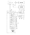
図2はこの参考例の制御系の概略構成を示すブロック図である。   FIG. 2 is a block diagram showing a schematic configuration of the control system of the reference example.

基板処理装置1と露光装置2と検査装置4とは、ホストコンピューター6を介して相互に接続されており、ホストコンピューター6を介して各装置1、2、4間で相互にデータの伝送が行えるように構成されている。   The substrate processing apparatus 1, the exposure apparatus 2, and the inspection apparatus 4 are interconnected via a host computer 6, and data can be transmitted between the apparatuses 1, 2, and 4 via the host computer 6. It is configured as follows.

基板処理装置1は、装置全体の動作管理などを行うメインコントローラー(CPU)19を備えている。また、各処理ユニット12〜17にはそれぞれの処理を制御するコントローラー(CPU)Ctが備えられ、基板搬送機構には基板の搬送動作の制御などを行うコントローラー(CPU)Ctが備えられている。メインコントローラー19と各コントローラーCtとは接続され、メインコントローラー19の制御情報などに基づき、基板が搬送され、各処理ユニット12〜17での処理が行われる。   The substrate processing apparatus 1 includes a main controller (CPU) 19 that manages the operation of the entire apparatus. Further, each of the processing units 12 to 17 is provided with a controller (CPU) Ct for controlling each process, and the substrate transport mechanism is provided with a controller (CPU) Ct for controlling a substrate transport operation and the like. The main controller 19 and each controller Ct are connected, and the substrate is transported based on the control information of the main controller 19 and the like, and the processing in each of the processing units 12 to 17 is performed.

また、第1のIFユニット3内の基板受渡しロボット31や第2のIFユニット5内の基板受渡しロボット51にも、各々の基板の受渡し動作の制御などを行うコントローラー(Ct)が備えられ、これらコントローラーCtもメインコントローラー19に接続されている。そして、例えば、基板の受渡しに関する露光装置2側のタイミング情報などが、露光装置2からホストコンピューター6、メインコントローラー19を介して第1のIFユニット3内の基板受渡しロボット31のコントローラーCtに与えられ、その情報に基づき、基板受渡しロボット31は露光装置2に対する基板の受渡し動作を行う。また、基板処理装置1に対する基板の受渡し動作はメインコントローラー19から与えられるタイミング情報などに基づき行われる。第2のIFユニット5内の基板受渡しロボット5による基板の受渡し動作も、上記第1のIFユニット3内の基板受渡しロボット31による基板の受渡し動作と同様の構成で行われる。   The board transfer robot 31 in the first IF unit 3 and the board transfer robot 51 in the second IF unit 5 are also provided with a controller (Ct) for controlling the transfer operation of each board. The controller Ct is also connected to the main controller 19. Then, for example, timing information on the exposure apparatus 2 side regarding the delivery of the substrate is provided from the exposure apparatus 2 to the controller Ct of the substrate delivery robot 31 in the first IF unit 3 via the host computer 6 and the main controller 19. Based on the information, the substrate transfer robot 31 performs a substrate transfer operation to the exposure apparatus 2. Further, the delivery operation of the substrate to the substrate processing apparatus 1 is performed based on timing information or the like given from the main controller 19. The substrate transfer operation by the substrate transfer robot 5 in the second IF unit 5 is also performed in the same configuration as the substrate transfer operation by the substrate transfer robot 31 in the first IF unit 3.

また、各装置1、2、4間で相互にデータの伝送が行えるので、検査装置4での検査結果が、ホストコンピューター6を介して基板処理装置1(メインコントローラー19)や露光装置2に与えることも可能である。基板処理装置1のメインコントローラー19に与えられた検査結果はメインコントローラー19から第3、第4の熱処理ユニット14、15や現像処理ユニット17に与えることができる。   In addition, since data can be transmitted between the apparatuses 1, 2, and 4 mutually, the inspection result of the inspection apparatus 4 is given to the substrate processing apparatus 1 (main controller 19) and the exposure apparatus 2 via the host computer 6. It is also possible. The inspection result given to the main controller 19 of the substrate processing apparatus 1 can be given from the main controller 19 to the third and fourth heat treatment units 14 and 15 and the development processing unit 17.

この参考例の動作は以下のとおりである。   The operation of this reference example is as follows.

すなわち、ローダ部11から搬入された基板は、第1の熱処理ユニット12でレジスト塗布処理前の熱処理が施され、次に、レジスト塗布処理ユニット16でレジスト膜の塗布処理が施された後、第2の熱処理ユニット13でレジスト塗布処理後の熱処理が施され、第1のIFユニット3を介して露光装置2に引き渡されて、露光処理が施される。露光装置2での露光処理を終えた基板は、第1のIFユニット3を介して露光装置2から第3の熱処理ユニット14に引き渡され、第3の熱処理ユニット14で露光処理後の熱処理が施され、次に、現像処理ユニット17で現像処理が施された後、検査を行う場合には、第2のIFユニット5を介して検査装置4に引き渡されて検査が行われる。そして、検査済の基板は、第2のIFユニット5を介して基板処理装置1(現像処理ユニット17)に再び戻され、第4の熱処理ユニット15に搬送されて現像処理後の熱処理が施され、アンローダ部18から搬出される。なお、検査を行わない基板は、現像処理ユニット17で現像処理が施された後、第4の熱処理ユニット15に搬送されて現像処理後の熱処理が施され、アンローダ部18から搬出される。   That is, the substrate carried in from the loader unit 11 is subjected to a heat treatment before the resist coating treatment in the first heat treatment unit 12, and then is subjected to the resist film coating treatment in the resist coating treatment unit 16. The second heat treatment unit 13 performs a heat treatment after the resist coating process, and is delivered to the exposure apparatus 2 via the first IF unit 3 and subjected to an exposure process. The substrate that has been subjected to the exposure processing in the exposure apparatus 2 is transferred from the exposure apparatus 2 to the third heat treatment unit 14 via the first IF unit 3, and subjected to a heat treatment after the exposure processing in the third heat treatment unit 14. Then, when the inspection is performed after the development processing is performed in the development processing unit 17, the inspection is transferred to the inspection device 4 via the second IF unit 5 and the inspection is performed. Then, the inspected substrate is returned to the substrate processing apparatus 1 (developing processing unit 17) again via the second IF unit 5, and is conveyed to the fourth thermal processing unit 15 where the thermal processing after the development processing is performed. , From the unloader unit 18. The substrate not subjected to the inspection is subjected to the development processing in the development processing unit 17, and then is transported to the fourth heat treatment unit 15, subjected to the heat treatment after the development processing, and is carried out from the unloader unit 18.

上述した一連の動作が連続的に、すなわち、未処理基板がローダ部11から次々に搬入され、基板の搬送や受渡し動作が連携して行われ、各処理ユニット12〜17や各装置2、4での処理や検査が同時並行して行われ、所定の処理(と検査)を終えた基板が次々にアンローダ部18から搬出されていく。   The above-described series of operations are continuously performed, that is, unprocessed substrates are successively carried in from the loader unit 11, and transfer and transfer operations of the substrates are performed in cooperation with each other, and the processing units 12 to 17 and the devices 2 and 4 are performed. Are performed simultaneously and in parallel, and the substrates that have been subjected to the predetermined processing (and inspection) are unloaded one after another from the unloader unit 18.

以上のように、この参考例の構成によれば、基板処理装置1と検査装置4との間で基板の受渡しを行う第1のIFユニット5(基板受渡しロボット51)を備えているので、検査装置4や基板処理装置1に対する基板の搬入、取り出しや、基板処理装置1と検査装置4との間の基板の搬送を自動的に行うことができ、作業者の負担を軽減できるとともに、基板の汚染や破損などの危険性が低減することができる。   As described above, according to the configuration of this reference example, since the first IF unit 5 (substrate transfer robot 51) that transfers the substrate between the substrate processing apparatus 1 and the inspection apparatus 4 is provided, the inspection is performed. The loading and unloading of substrates to and from the apparatus 4 and the substrate processing apparatus 1 and the transfer of substrates between the substrate processing apparatus 1 and the inspection apparatus 4 can be performed automatically, so that the burden on the operator can be reduced and Risks such as contamination and breakage can be reduced.

また、メインコントローラー19が実行するプログラムなどを変更することで、基板処理装置1で行う各処理と検査装置4で行う検査とを交えた動作を種々のパターンで行うことが可能となる。例えば、現像処理を終えた全ての基板を検査(全数検査)するように動作させたり、所定の基板だけを検査装置4に引き渡して検査(抜き打ち検査)させたりするように動作させることが可能である。   In addition, by changing a program or the like executed by the main controller 19, it is possible to perform an operation including each processing performed by the substrate processing apparatus 1 and an inspection performed by the inspection apparatus 4 in various patterns. For example, it is possible to operate so as to inspect all the substrates that have completed the developing process (inspection of all the substrates) or to deliver only a predetermined substrate to the inspection device 4 to inspect (periodic inspection). is there.

また、検査装置4での検査結果を、適宜の表示器に表示したり、適宜の記憶装置に保存したりすることで、基板処理の状態などの管理を行うことができる。さらに、検査結果を基板処理装置1(メインコントローラー19)や露光装置2に与えれば、露光装置2や、基板処理装置1内の現像処理ユニット17、露光処理後の熱処理を行う第3、第4の熱処理ユニット14、15などで検査結果を利用することができ、今後の露光処理や加熱処理、現像処理の処理条件(露光処理におけるアライメント条件や露光量などの露光処理条件、加熱処理時の加熱温度や加熱時間などの加熱処理条件、現像処理時の現像時間や現像液の温度などの現像処理条件など)に反映させることもできる。   In addition, by displaying the inspection result of the inspection device 4 on an appropriate display device or storing the inspection result in an appropriate storage device, it is possible to manage the state of the substrate processing. Further, if the inspection result is given to the substrate processing apparatus 1 (main controller 19) and the exposure apparatus 2, the exposure apparatus 2, the development processing unit 17 in the substrate processing apparatus 1, and the third and fourth heat treatments after the exposure processing are performed. Inspection results can be used in the heat treatment units 14 and 15 of the present invention, and the processing conditions of future exposure processing, heating processing, and development processing (exposure processing conditions such as alignment conditions and exposure amount in exposure processing, heating during heating processing) Heat treatment conditions such as temperature and heating time, and development processing conditions such as the development time during the development process and the temperature of the developing solution).

また、この参考例の構成によれば、基板処理装置1と露光装置2との間で基板の受渡しを行う第1のIFユニット3(基板受渡しロボット31)を備えているので、フォトリソグラフィ工程の各処理を自動的に、かつ、連続的に行うことができる。   In addition, according to the configuration of this reference example, since the first IF unit 3 (substrate transfer robot 31) that transfers a substrate between the substrate processing apparatus 1 and the exposure apparatus 2 is provided, a photolithography process is performed. Each process can be performed automatically and continuously.

〔参考例の変形例〕
図3(a)、(b)に示すように、基板処理装置1に備える処理ユニットが、露光処理後の熱処理を行う第3、第4の熱処理ニット14、15と現像処理ユニット17のみの構成であってもよい。図3(a)の構成では、露光処理を終えた基板がローダ部11から基板処理装置1に搬入される。また、図3(b)の構成では、露光処理前の所定の処理を終えた基板がローダ部11から搬入され、第1のIFユニット3を介して露光装置2に引き渡されて露光処理が施され、露光処理済の基板が第1のIFユニット3を介して第3の熱処理ユニット14に引き渡される。
(Modification of Reference Example)
As shown in FIGS. 3A and 3B, the processing unit provided in the substrate processing apparatus 1 has only the third and fourth heat treatment knits 14 and 15 for performing the heat treatment after the exposure processing and the development processing unit 17. It may be. In the configuration of FIG. 3A, the substrate after the exposure processing is carried into the substrate processing apparatus 1 from the loader unit 11. Further, in the configuration of FIG. 3B, a substrate that has been subjected to a predetermined process before the exposure process is carried in from the loader unit 11 and delivered to the exposure apparatus 2 via the first IF unit 3, where the exposure process is performed. Then, the exposed substrate is transferred to the third heat treatment unit 14 via the first IF unit 3.

図4(a)に示すように、第2のIFユニット5の一方の側面を基板処理装置1の現像処理ユニット17と第4の熱処理ユニット15とに隣接させて配置するとともに、基板受渡しロボット51(アーム支持台51b)を図のX方向に往復移動可能に構成して、現像処理を終えた基板を現像処理ユニット17から第2のIFユニット5を介して検査装置4に引き渡し、検査済の基板を第2のIFユニット5を介して第4の熱処理ユニット15に引き渡して第4の熱処理ユニット15で現像処理後の熱処理を行うように構成してもよい。また、図4(b)に示すように、第1のIFユニット5の一方の側面を基板処理装置1の第4の熱処理ユニット15に隣接させて配置し、現像処理後の熱処理を終えた基板を第4の熱処理ユニット15から第2のIFユニット5を介して検査装置4に引き渡し、検査済の基板を第2のIFユニット5を介して第4の熱処理ユニット15に引き渡してアンローダ部18に搬送してそこから搬出させるように構成してもよい。さらに、図4(c)に示すように、第1のIFユニット5の一方の側面を基板処理装置1の第4の熱処理ユニット15とアンローダ部18とに隣接させて配置するとともに、基板受渡しロボット51(アーム支持台51b)を図のX方向に往復移動可能に構成して、現像処理後の熱処理を終えた基板を第4の熱処理ユニット15から第2のIFユニット5を介して検査装置4に引き渡し、検査済の基板を第2のIFユニット5を介してアンローダ部18に引き渡してそこから搬出させるように構成してもよい。なお、図4の各図に示す変形例は、図3の各図に示す変形例にも同様に適用することができる。   As shown in FIG. 4A, one side surface of the second IF unit 5 is arranged adjacent to the development processing unit 17 and the fourth heat treatment unit 15 of the substrate processing apparatus 1 and the substrate transfer robot 51 The (arm support 51b) is configured to be reciprocally movable in the X direction in the figure, and the substrate after the development processing is delivered from the development processing unit 17 to the inspection device 4 via the second IF unit 5, and the inspection is completed. The substrate may be delivered to the fourth heat treatment unit 15 via the second IF unit 5 so that the fourth heat treatment unit 15 performs heat treatment after the development processing. Further, as shown in FIG. 4B, one side surface of the first IF unit 5 is arranged adjacent to the fourth heat treatment unit 15 of the substrate processing apparatus 1, and the heat treatment after the development processing is completed. Is transferred from the fourth heat treatment unit 15 to the inspection device 4 via the second IF unit 5, and the inspected substrate is transferred to the fourth heat treatment unit 15 via the second IF unit 5 and is sent to the unloader section 18. You may comprise so that it may be conveyed and carried out from there. Further, as shown in FIG. 4C, one side surface of the first IF unit 5 is arranged adjacent to the fourth heat treatment unit 15 and the unloader section 18 of the substrate processing apparatus 1, and the substrate transfer robot is provided. 51 (arm support table 51 b) is configured to be reciprocally movable in the X direction in the figure, and the substrate subjected to the heat treatment after the development processing is inspected from the fourth heat treatment unit 15 via the second IF unit 5 by the inspection device 4. And the inspected board may be delivered to the unloader section 18 via the second IF unit 5 and carried out therefrom. In addition, the modification shown in each figure of FIG. 4 can be similarly applied to the modification shown in each figure of FIG.

図5に示すように、検査装置4をユニット化して基板処理装置1内に組み込み、現像処理ユニット17と第4の熱処理ユニット15との間(図5(a))、または、第4の熱処理ユニット15とアンローダ部18との間(図5(b))に配置させるように構成してもよい。図5の各図に示す変形例は、図3の各図に示す変形例にも同様に適用することができる。   As shown in FIG. 5, the inspection apparatus 4 is unitized and incorporated into the substrate processing apparatus 1, and is provided between the developing processing unit 17 and the fourth heat treatment unit 15 (FIG. 5A) or the fourth heat treatment. You may comprise so that it may be arrange | positioned between the unit 15 and the unloader part 18 (FIG.5 (b)). The modification shown in each drawing of FIG. 5 can be similarly applied to the modification shown in each drawing of FIG.

<第1実施例>
図6は本発明の第1実施例に係る基板処理装置及びその基板処理装置を含む基板処理システムの全体構成を示す平面図である。なお、この第1実施例において、上記参考例と共通する部分または同様の機能を有する部分は、図1と同一符号を付して、特に必要がある場合以外は、その説明は省略する。
<First embodiment>
FIG. 6 is a plan view showing the entire configuration of the substrate processing apparatus and the substrate processing system including the substrate processing apparatus according to the first embodiment of the present invention. In the first embodiment, the same reference numerals as in FIG. 1 denote parts common to the above-described reference examples or parts having similar functions, and a description thereof will be omitted unless it is particularly necessary.

この第1実施例は、基板処理装置1の構成と、露光装置2や検査装置4の配置とが参考例のものと相違する。   In the first embodiment, the configuration of the substrate processing apparatus 1 and the arrangement of the exposure apparatus 2 and the inspection apparatus 4 are different from those of the reference example.

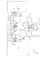
第1実施例の基板処理装置1は、インデクサ部70と基板処理部80とを備えている。インデクサ部70には、所定方向に延びた受渡し用搬送路71と、その一方の側部側に配置されたカセット載置台72と、受渡し用搬送路71に設けられた受渡し用基板搬送手段に相当する受渡し用基板搬送ロボット73を備えている。基板処理部80は、受渡し用搬送路71の他方の側部側に配置されている。また、露光装置2は、第1のIFユニット3を間に挟んで受渡し用搬送路71の一方の端部の近くに配置され、第1のIFユニット3は、一方の側面が受渡し用搬送路71の一方の端部に隣接し、他方の側面が露光装置2に隣接して配置されている。さらに、検査装置4は、第2のIFユニット5を間に挟んで受渡し用搬送路71の他方の端部の近くに配置され、第2のIFユニット5は、一方の側面が受渡し用搬送路71の他方の端部に隣接し、他方の側面が検査装置4に隣接して配置されている。   The substrate processing apparatus 1 according to the first embodiment includes an indexer unit 70 and a substrate processing unit 80. The indexer unit 70 includes a transfer path 71 extending in a predetermined direction, a cassette mounting table 72 disposed on one side of the transfer path 71, and a transfer board transfer unit provided in the transfer path 71. The transfer substrate transfer robot 73 is provided. The substrate processing section 80 is arranged on the other side of the transfer path 71. The exposure apparatus 2 is disposed near one end of the transfer path 71 with the first IF unit 3 interposed therebetween. 71 is arranged adjacent to one end and the other side surface is arranged adjacent to the exposure apparatus 2. Further, the inspection device 4 is disposed near the other end of the delivery transport path 71 with the second IF unit 5 interposed therebetween. 71 is arranged adjacent to the other end, and the other side surface is arranged adjacent to the inspection device 4.

インデクサ部70のカセット載置台72には、基板収納部としての装置間搬送用のカセット74を複数個(図では4個)載置し得るように構成されている。各カセット74は複数枚の基板Wを鉛直方向(図6の紙面に垂直な方向)に多段に積層して水平姿勢で収納し得るように構成されている。これら各カセット74は、受渡し用搬送路71の長手方向(図6のY方向)に沿ってカセット載置台72に載置されるようになっている。   The cassette mounting table 72 of the indexer unit 70 is configured such that a plurality of (four in the figure) cassettes 74 for transporting between apparatuses as a substrate storage unit can be mounted. Each cassette 74 is configured such that a plurality of substrates W can be stacked in a vertical direction (a direction perpendicular to the plane of FIG. 6) in multiple stages and stored in a horizontal posture. Each of these cassettes 74 is mounted on the cassette mounting table 72 along the longitudinal direction (Y direction in FIG. 6) of the transfer path 71 for delivery.

受渡し用基板搬送ロボット73は、基板Wを保持する基板保持アーム73aと基板保持アーム73aを支持するアーム支持台73bとを備えている。基板保持アーム73aは、平面視で略Iの字形状を有し、アーム支持台73bに対して水平方向(図6の紙面に平行な方向)に進退移動可能に構成されている。また、アーム支持台73bは、受渡し用搬送路71の長手方向に沿ったY方向への往復移動(基板保持アーム73aの進退移動のY方向の位置の変更))や鉛直方向への昇降移動(基板保持アーム73aの高さ位置の変更)が可能であるとともに、鉛直方向の軸芯Q1周りでの旋回(水平面内における基板保持アーム73aの進退移動方向の変更)なども可能に構成されている。   The transfer substrate transfer robot 73 includes a substrate holding arm 73a that holds the substrate W and an arm support 73b that supports the substrate holding arm 73a. The substrate holding arm 73a has a substantially I-shape in plan view, and is configured to be able to advance and retreat in a horizontal direction (a direction parallel to the paper surface of FIG. 6) with respect to the arm support 73b. Further, the arm support base 73b reciprocates in the Y direction along the longitudinal direction of the transfer path 71 for transfer (change of the position of the forward and backward movement of the substrate holding arm 73a in the Y direction) and moves up and down in the vertical direction ( In addition to being capable of changing the height position of the substrate holding arm 73a), it is also configured to be capable of turning around the axis Q1 in the vertical direction (changing the moving direction of the substrate holding arm 73a in the horizontal plane). .

受渡し用基板搬送ロボット73は、アーム支持台73bや基板保持アーム73aの各動作を適宜に組み合わせて、受渡し用搬送路71での基板Wの搬送と、所望のカセット74の所定の基板Wの収納場所に対する基板Wの出し入れと、基板処理部80に備えられた処理部用基板搬送ロボット81との間での基板Wの受渡しと、第1のIFユニット3内の基板受渡しロボット31との間での基板Wの受渡しと、第2のIFユニット5内の基板受渡しロボット51との間での基板Wの受渡しとを行うように構成されている。   The transfer substrate transfer robot 73 transfers the substrate W in the transfer path 71 and stores a predetermined substrate W in a desired cassette 74 by appropriately combining the operations of the arm support table 73b and the substrate holding arm 73a. The transfer of the substrate W to / from the place, the transfer of the substrate W to / from the processing unit substrate transfer robot 81 provided in the substrate processing unit 80, and the transfer of the substrate W to / from the substrate transfer robot 31 in the first IF unit 3. And the transfer of the substrate W to and from the substrate transfer robot 51 in the second IF unit 5.

基板処理部80は、処理部用基板搬送手段に相当する処理部用基板搬送ロボット81を中央に備え、処理部用基板搬送ロボット81を囲むようにその周囲にレジスト塗布処理ユニット16、現像処理ユニット17、熱処理ユニットTPが配置されている。各処理ユニット16、17、TPは、1段目にレジスト塗布処理ユニット16や現像処理ユニット17(図6ではそれぞれ2台ずつ)が配置され、その上に複数の熱処理ユニットTPが積層されている。なお、本実施例では、任意の熱処理ユニットTPが選ばれて、レジスト塗布処理前後の熱処理や、露光処理後の熱処理、現像処理後の熱処理などの各種の熱処理が行われる。   The substrate processing unit 80 includes a processing unit substrate transfer robot 81 corresponding to a processing unit substrate transfer unit at the center, and a resist coating processing unit 16 and a development processing unit around the processing unit substrate transfer robot 81 so as to surround the processing unit substrate transfer robot 81. 17, a heat treatment unit TP is provided. In each of the processing units 16, 17, and TP, a resist coating processing unit 16 and a development processing unit 17 (two each in FIG. 6) are arranged in the first stage, and a plurality of heat treatment units TP are stacked thereon. . In this embodiment, an arbitrary heat treatment unit TP is selected, and various heat treatments such as heat treatment before and after resist coating, heat treatment after exposure, and heat treatment after development are performed.

処理部用基板搬送ロボット81は、基板Wを保持する基板保持アーム81aと基板保持アーム81aを支持するアーム支持台81bとを備えている。基板保持アーム81aは、平面視で略Uの字形状を有し、アーム支持台81bに対して水平方向に進退移動可能に構成されている。また、この実施例では、アーム支持台73bは、昇降移動(基板保持アーム81aの高さ位置の変更)が可能で、鉛直方向の軸芯Q2周りでの旋回(水平面内における基板保持アーム81aの進退移動方向の変更)なども可能に構成されている。   The substrate transfer robot 81 for a processing unit includes a substrate holding arm 81a for holding a substrate W and an arm support table 81b for supporting the substrate holding arm 81a. The substrate holding arm 81a has a substantially U-shape in plan view, and is configured to be able to advance and retreat in the horizontal direction with respect to the arm support 81b. Further, in this embodiment, the arm support 73b can move up and down (change the height position of the substrate holding arm 81a), and can turn around the vertical axis Q2 (the substrate holding arm 81a in a horizontal plane). (Change of the forward / backward moving direction) is also possible.

処理部用基板搬送ロボット81は、アーム支持台81bや基板保持アーム81aの各動作を適宜に組み合わせて、基板処理部80内に配置された各処理ユニット16、17、TP間の基板Wの搬送と、各処理ユニット16、17、TPとの間での基板Wの受渡しと、受渡し用基板搬送ロボット73との間での基板Wの受渡しとを行うように構成されている。   The processing unit substrate transfer robot 81 transfers the substrate W between the processing units 16, 17, and TP arranged in the substrate processing unit 80 by appropriately combining the operations of the arm support base 81 b and the substrate holding arm 81 a. And the transfer of the substrate W to and from each of the processing units 16, 17 and TP, and the transfer of the substrate W to and from the transfer substrate transfer robot 73.

この第1実施例の制御系の構成も参考例と同様の構成(図2参照)を有する。   The configuration of the control system of the first embodiment also has the same configuration as that of the reference example (see FIG. 2).

この第1実施例の動作は以下のとおりである。   The operation of the first embodiment is as follows.

まず、受渡し用基板搬送ロボット73がカセット74から未処理の基板Wを取り出し、その未処理基板Wを受渡し用搬送路71で搬送して、基板処理部80内の処理部用基板搬送ロボット81にその未処理基板Wを引き渡す。   First, the transfer substrate transfer robot 73 takes out the unprocessed substrate W from the cassette 74, transfers the unprocessed substrate W through the transfer transfer path 71, and sends the unprocessed substrate W to the processing unit substrate transfer robot 81 in the substrate processing unit 80. The unprocessed substrate W is delivered.

処理部用基板搬送ロボット81は、受け取った未処理基板Wを処理ユニット16、TP間で搬送し、レジスト塗布処理前の熱処理を行う熱処理ユニットTP、レジスト塗布処理ユニット16、レジスト塗布処理後の熱処理を行う熱処理ユニットTPに順次基板Wを受け渡していき、露光処理前の一連の処理を行わせる。露光処理前の処理を終えた基板Wは、処理部用基板搬送ロボット81から受渡し用基板搬送ロボット73に引き渡される。   The processing unit substrate transport robot 81 transports the received unprocessed substrate W between the processing units 16 and TP, and performs a heat treatment before the resist coating processing, a heat treatment unit TP, the resist coating processing unit 16, and a heat treatment after the resist coating processing. Are sequentially delivered to the heat treatment unit TP for performing the series of processes before the exposure process. The substrate W which has completed the processing before the exposure processing is transferred from the processing section substrate transfer robot 81 to the delivery substrate transfer robot 73.

露光処理前の基板Wを受け取った受渡し用基板搬送ロボット73は、その基板Wを第1のIFユニット3(基板受渡しロボット31)を介して露光装置2に引き渡す。そして、露光装置2で露光処理を受けた露光処理済の基板Wは、露光装置2から第1のIFユニット3を介して受渡し用基板搬送ロボット73に受け渡される。   The transfer substrate transfer robot 73 having received the substrate W before the exposure processing transfers the substrate W to the exposure apparatus 2 via the first IF unit 3 (substrate transfer robot 31). Then, the exposed substrate W subjected to the exposure processing by the exposure device 2 is transferred from the exposure device 2 to the transfer substrate transfer robot 73 via the first IF unit 3.

露光処理済の基板Wを受け取った受渡し用基板搬送ロボット73はその基板Wを処理部用基板搬送ロボット81に引き渡す。処理部用基板搬送ロボット81は、受け取った露光処理済の基板Wを処理ユニット17、TP間で搬送し、露光処理後の熱処理を行う熱処理ユニットTP、現像処理ユニット17、現像処理後の熱処理を行う熱処理ユニットTPに順次基板Wを受け渡していき、露光処理後の一連の処理を行わせる。露光処理後の処理を終えた基板Wは、処理部用基板搬送ロボット81から受渡し用基板搬送ロボット73に引き渡される。   The transfer substrate transfer robot 73 that has received the exposed substrate W transfers the substrate W to the processing unit substrate transfer robot 81. The processing unit substrate transport robot 81 transports the received exposure-processed substrate W between the processing units 17 and TP and performs a heat treatment after the exposure processing, a development processing unit 17, and a heat treatment after the development processing. The substrate W is sequentially delivered to the heat treatment unit TP to be performed, and a series of processes after the exposure process are performed. The substrate W after the processing after the exposure processing is delivered from the processing section substrate transport robot 81 to the delivery substrate transport robot 73.

露光処理後の処理を終えた基板Wが検査対象の基板Wでなければ、その基板Wは受渡し用基板搬送ロボット73によりカセット74に収納される。   If the substrate W after the exposure processing is not the inspection target substrate W, the substrate W is stored in the cassette 74 by the transfer substrate transport robot 73.

一方、露光処理後の処理を終えた基板Wが検査対象の基板Wであれば、その基板Wは、受渡し用基板搬送ロボット73から第2のIFユニット5(基板受渡しロボット51)を介して検査装置4に引き渡され、検査装置4で所定の検査を受けた後、検査済の基板Wが、検査装置4から第2のIFユニット5を介して受渡し用基板搬送ロボット73に受け渡され、受渡し用基板搬送ロボット73によりカセット74に収納される。   On the other hand, if the substrate W after the exposure processing is the substrate W to be inspected, the substrate W is inspected from the transfer substrate transfer robot 73 via the second IF unit 5 (substrate transfer robot 51). After being delivered to the device 4 and undergoing a predetermined inspection by the inspection device 4, the inspected substrate W is delivered from the inspection device 4 to the delivery substrate transport robot 73 via the second IF unit 5 and is delivered. Is stored in the cassette 74 by the substrate transfer robot 73.

この第1実施例では、上述した一連の動作が連続的に、すなわち、未処理基板Wがカセット74から次々に取り出され、各基板搬送ロボット73、81や各基板受渡しロボット31、51などが連携して動作し、各処理ユニット16、17、TPや各装置2、4での処理や検査が同時並行して行われ、所定の処理(と検査)を終えた基板Wが次々にカセット74に収納されていく。   In the first embodiment, the above-described series of operations are continuously performed, that is, the unprocessed substrates W are sequentially taken out of the cassette 74, and the substrate transfer robots 73 and 81 and the substrate transfer robots 31 and 51 cooperate. The processing and inspection in each of the processing units 16 and 17 and the TP and each of the devices 2 and 4 are performed simultaneously and in parallel, and the substrates W that have been subjected to the predetermined processing (and inspection) are successively stored in the cassette 74. It will be stored.

なお、この第1実施例で、現像処理を終えた基板Wを検査する場合には、以下のように動作する。   In the first embodiment, the following operation is performed when inspecting the substrate W after the development processing.

すなわち、上述と同様の動作で現像処理まで行われ、現像処理を終えると、その現像処理を終えた基板Wが処理部用基板搬送ロボット81から受渡し用基板搬送ロボット73に引き渡され、受渡し用基板搬送ロボット73から第2のIFユニットを介して検査装置4に引き渡される。そして、検査装置4で所定の検査を受けた後、検査済の基板Wが、検査装置4から第2のIFユニット5を介して受渡し用基板搬送ロボット73に引き渡されて、受渡し用基板搬送ロボット73から処理部用基板搬送ロボット81に引き渡される。処理部用基板搬送ロボット81は、受け取った検査済の基板Wを現像処理後の熱処理を行う熱処理ユニットTPに引き渡して、現像処理後の熱処理を行わせる。処理後の基板Wは、処理部用基板搬送ロボット81から受渡し用基板搬送ロボット73に引き渡され、受渡し用基板搬送ロボット73によりカセット74に収納される。   That is, the same processing as described above is performed up to the development processing. When the development processing is completed, the substrate W after the development processing is delivered from the processing unit substrate transport robot 81 to the delivery substrate transport robot 73, and the delivery substrate is delivered. It is delivered to the inspection device 4 from the transfer robot 73 via the second IF unit. After the inspection device 4 has undergone a predetermined inspection, the inspected substrate W is transferred from the inspection device 4 to the transfer substrate transfer robot 73 via the second IF unit 5, and the transfer substrate transfer robot 73 From 73, the substrate is transferred to the processing unit substrate transfer robot 81. The processing unit substrate transport robot 81 transfers the received inspected substrate W to the heat treatment unit TP that performs the heat treatment after the development processing, and performs the heat treatment after the development processing. The processed substrate W is transferred from the processing section substrate transfer robot 81 to the transfer substrate transfer robot 73, and is stored in the cassette 74 by the transfer substrate transfer robot 73.

この第1実施例の構成によっても、参考例と同様の効果を得ることができる。また、それに加えて、この第1実施例の構成によれば、受渡し用搬送路71を挟んでカセット74と基板処理部80が配置され、カセット74に対する基板Wの出し入れと、基板処理部80内の処理部用基板搬送ロボット81との間の基板Wの受渡しとを受渡し用基板搬送ロボット73が行うように構成しているので、基板処理装置のコンパクト化を図ることができる。また、受渡し用搬送路71の各端部にそれぞれ、第1のIFユニット3及び露光装置2と、第2のIFユニット5及び検査装置4とを配置しているので、露光装置2や検査装置4を含めた各装置1、2、4をコンパクトに設置することができる。   According to the configuration of the first embodiment, the same effect as that of the reference example can be obtained. In addition, according to the configuration of the first embodiment, the cassette 74 and the substrate processing unit 80 are arranged with the transfer path 71 interposed therebetween. Since the transfer of the substrate W to and from the processing unit substrate transfer robot 81 is performed by the transfer substrate transfer robot 73, the size of the substrate processing apparatus can be reduced. In addition, since the first IF unit 3 and the exposure device 2 and the second IF unit 5 and the inspection device 4 are disposed at each end of the transfer path 71, the exposure device 2 and the inspection device 4 can be compactly installed.

<第2実施例>
図7は本発明の第2実施例に係る基板処理装置の構成を示す平面図である。なお、この第2実施例において、上記参考例および第1実施例と共通する部分または同様の機能を有する部分は、図1、図6と同一符号を付して、特に必要がある場合以外は、その説明は省略する。また、図7では、受渡し用基板搬送ロボット73、各IFユニット3、5内の基板受渡しロボット31、51を簡略化して図示しているが、これらロボット73、31、51は第1実施例のものと同様の構成である。
<Second embodiment>
FIG. 7 is a plan view showing the configuration of the substrate processing apparatus according to the second embodiment of the present invention. In the second embodiment, portions common to the above-described reference example and the first embodiment or portions having similar functions are denoted by the same reference numerals as in FIGS. 1 and 6, and unless otherwise required. , The description of which is omitted. In FIG. 7, the transfer substrate transfer robot 73 and the substrate transfer robots 31 and 51 in each of the IF units 3 and 5 are shown in a simplified manner. The configuration is similar to that of the first embodiment.

この第2実施例は、基板処理装置1の基板処理部80の構成が第1実施例のものと相違する。   The second embodiment is different from the first embodiment in the configuration of the substrate processing unit 80 of the substrate processing apparatus 1.

この第2実施例に係る基板処理装置1の基板処理部80は、受渡し用搬送路71に直交する方向(図7のX方向)に延びる処理部用搬送路82を備え、この処理部用搬送路82を間に挟んでその両側部側に、処理部用搬送路82に沿って各処理ユニット16、17、TPが配置されている。この構成においては、処理部用搬送路82の一方の側部側に熱処理関係の熱処理ユニットTPが配置され、処理部用搬送路82の他方の側部側に非熱処理関係のレジスト塗布処理ユニット16と現像処理ユニット17が配置される。   The substrate processing unit 80 of the substrate processing apparatus 1 according to the second embodiment includes a processing unit transfer path 82 extending in a direction (X direction in FIG. 7) orthogonal to the transfer path 71 for transfer. The processing units 16, 17, and TP are arranged along the processing unit transport path 82 on both sides of the path 82. In this configuration, a heat treatment unit TP related to heat treatment is arranged on one side of the transfer path 82 for the processing unit, and the resist coating unit 16 related to the non-heat treatment is arranged on the other side of the transfer path 82 for the processing unit. And a developing unit 17 are arranged.

また、処理部用基板搬送ロボット81は、アーム支持台81bに対する基板保持アーム81aの水平方向への進退移動と、アーム支持台81bの昇降移動及び軸芯Q2周りでの旋回に加えて、処理部用搬送路82の長手方向に沿った水平移動(図7のX方向への往復移動)も行えるように構成されている。   Further, the processing unit substrate transfer robot 81 performs the horizontal movement of the substrate holding arm 81a with respect to the arm support base 81b, the vertical movement of the arm support base 81b, and the rotation around the axis Q2. It is configured such that horizontal movement (reciprocal movement in the X direction in FIG. 7) along the longitudinal direction of the transfer path 82 can also be performed.

この第2実施例の構成によっても第1実施例と同様の効果を得ることができる。   According to the configuration of the second embodiment, the same effect as that of the first embodiment can be obtained.

<第3実施例>
図8は本発明の第3実施例に係る基板処理装置の要部であるインデクサ部の構成を示す平面図であり、図9は第3実施例に係る基板処理装置のインデクサ部を第1のIFユニット側から見た縦断面図、図10は第3実施例に係る基板処理装置のインデクサ部を基板処理部側から見た縦断面図である。なお、この第3実施例において、上記第1、第1実施例と共通する部分または同様の機能を有する部分は、図1、図6と同一符号を付して、特に必要がある場合以外は、その説明は省略する。
<Third embodiment>
FIG. 8 is a plan view showing a configuration of an indexer section which is a main part of the substrate processing apparatus according to the third embodiment of the present invention, and FIG. 9 is a plan view of the indexer section of the substrate processing apparatus according to the third embodiment. FIG. 10 is a vertical sectional view of the indexer unit of the substrate processing apparatus according to the third embodiment as viewed from the substrate processing unit side. In the third embodiment, portions common to the first and first embodiments or portions having the same functions are denoted by the same reference numerals as in FIGS. 1 and 6, and unless otherwise required. , The description of which is omitted.

この第3実施例は、受渡し用基板搬送手段を複数台の基板搬送ロボットで構成したものである。なお、図では、基板処理部80の構成を省略しているが、この基板処理部80は、第1実施例で示した構成であってもよいし、第2実施例で示した構成であってもよい。   In the third embodiment, the transfer substrate transfer means is constituted by a plurality of substrate transfer robots. Although the configuration of the substrate processing unit 80 is omitted in the figure, the substrate processing unit 80 may have the configuration shown in the first embodiment or the configuration shown in the second embodiment. You may.

この第3実施例では、基板処理装置1のインデクサ部70の受渡し用基板搬送手段を6台の第1〜第6基板搬送ロボット91〜96で構成している。   In the third embodiment, the transfer substrate transfer means of the indexer unit 70 of the substrate processing apparatus 1 is constituted by six first to sixth substrate transfer robots 91 to 96.

カセット載置台72側に配置された第1基板搬送ロボット91は、第1実施例の受渡し用基板搬送ロボット73と同様の構成を有する。図中の符号91a、91bは、受渡し用基板搬送ロボット73の基板保持アーム73a、アーム支持台73bに対応する基板保持アームとアーム支持台を示す。   The first substrate transfer robot 91 disposed on the cassette mounting table 72 side has the same configuration as the transfer substrate transfer robot 73 of the first embodiment. Reference numerals 91a and 91b in the figure indicate a substrate holding arm and an arm support corresponding to the substrate holding arm 73a and the arm support 73b of the transfer substrate transfer robot 73.

第2〜第6基板搬送ロボット92〜96は、第1基板搬送ロボット91のY方向への往復移動の移動領域よりも基板処理部80側に配置されている。第2基板搬送ロボット92は、鉛直方向(Z方向)に設定された3段階の高さ階層のうちの最も低い第1の高さ階層H1において、処理部用基板搬送ロボット81の正面側に配置されている。第3基板搬送ロボット93は、第2基板搬送ロボット92の上方において中間高さの第2の高さ階層H2に配置され、第4基板搬送ロボット94は、第3基板搬送ロボット93の上方において最も高い第3の高さ階層H3に配置されている。第2〜第4基板搬送ロボット92〜94は同じ構造を有している。これら基板搬送ロボット92〜94は、図11に示すように、それぞれ基板保持フレーム97aと、基板保持フレーム97aを支持するアーム支持台97bとを備えている。この基板保持フレーム97aはアーム支持台97bに対して処理部用基板搬送ロボット81に向けた進退移動が可能に構成されている。アーム支持台97bは各々の高さ階層H1〜H3内で昇降移動(基板保持アーム97aの高さ位置の変更)が可能に構成されている。この基板保持フレーム97aには、4本の基板保持ピン97cが立設されている。これら基板支持ピン97cは段付き構造で構成され、基板Wの外周部を載置支持するとともに、基板Wの外周端縁に接触して基板Wの水平移動を規制することで、基板保持フレーム97aから浮かせた状態で基板Wを保持する。   The second to sixth substrate transfer robots 92 to 96 are arranged closer to the substrate processing unit 80 than the reciprocating movement area of the first substrate transfer robot 91 in the Y direction. The second substrate transfer robot 92 is disposed on the front side of the processing unit substrate transfer robot 81 at the lowest first level H1 of the three levels set in the vertical direction (Z direction). Have been. The third substrate transfer robot 93 is disposed above the second substrate transfer robot 92 on the second height level H2 having an intermediate height, and the fourth substrate transfer robot 94 is disposed above the third substrate transfer robot 93 at the highest position. It is arranged on the third higher level H3. The second to fourth substrate transfer robots 92 to 94 have the same structure. As shown in FIG. 11, each of the substrate transport robots 92 to 94 includes a substrate holding frame 97a and an arm support base 97b that supports the substrate holding frame 97a. The substrate holding frame 97a is configured to be capable of moving forward and backward with respect to the arm support base 97b toward the processing unit substrate transfer robot 81. The arm support base 97b is configured to be able to move up and down (change the height position of the substrate holding arm 97a) in each of the height levels H1 to H3. Four board holding pins 97c are provided upright on the board holding frame 97a. These substrate support pins 97c are configured in a stepped structure, and place and support the outer peripheral portion of the substrate W, and contact the outer peripheral edge of the substrate W to restrict the horizontal movement of the substrate W, so that the substrate holding frame 97a The substrate W is held in a state where the substrate W is floated.

第5基板搬送ロボット95は、第2の高さ階層H2において、第3基板搬送ロボット93の第2のIFユニット5側の側方に配置され、第6基板搬送ロボット96は、第3の高さ階層H3において、第4基板搬送ロボット94の第1のIFユニット3側の側方に配置されている。第5、第6基板搬送ロボット95、96は同じ構造を有している。これら基板搬送ロボット95、96は、それぞれ平面視で略Iの字形状を有する基板保持アーム98aと、基板保持アーム98aを支持するアーム支持台98bとを備えている。この基板保持アーム98aはアーム支持台98bに対して進退移動が可能に構成され、アーム支持台98bは、昇降移動(基板保持アーム98aの高さ位置の変更)が可能で、鉛直方向の軸芯Q3、Q4周りで旋回(水平面内における基板保持アーム98aの進退移動方向の変更)も可能に構成されている。   The fifth substrate transfer robot 95 is disposed on the second IF unit 5 side of the third substrate transfer robot 93 in the second height hierarchy H2, and the sixth substrate transfer robot 96 is connected to the third height H3. In the layer H3, the fourth substrate transfer robot 94 is arranged on the side of the first IF unit 3 side. The fifth and sixth substrate transfer robots 95 and 96 have the same structure. Each of the substrate transfer robots 95 and 96 includes a substrate holding arm 98a having a substantially I shape in plan view, and an arm support base 98b that supports the substrate holding arm 98a. The substrate holding arm 98a is configured to be capable of moving forward and backward with respect to the arm support base 98b, and the arm support base 98b is capable of moving up and down (changing the height position of the substrate holding arm 98a) and has a vertical axis. Turning around Q3 and Q4 (changing the direction of movement of the substrate holding arm 98a in the horizontal plane) is also possible.

この第3実施例では基板Wの搬送や受渡しなどは以下のように行われる。   In the third embodiment, the transfer and delivery of the substrate W are performed as follows.

カセット74からの基板Wの取り出しは第1基板搬送ロボット91により行われ、この基板Wは、第1基板搬送ロボット91から第2基板搬送ロボット92に引き渡され、第2基板搬送ロボット92から処理部用基板搬送ロボット81に引き渡され、基板処理部80で露光処理前の一連の処理が施される。露光処理前の処理を終えた基板Wは、処理部用基板搬送ロボット81から第4基板搬送ロボット94に引き渡され、第4基板搬送ロボット94から第6基板搬送ロボット96に引き渡され、第6基板搬送ロボット96から第1のIFユニット3内の基板受渡しロボット31に引き渡されて露光装置2に引き渡される。露光処理を終えた基板Wは、上記と逆の流れで、第1のIFユニット3内の基板受渡しロボット31、第6基板搬送ロボット96、第4基板搬送ロボット94を介して処理部用基板搬送ロボット81に引き渡されて、基板処理部80で露光処理後の一連の処理が施される。露光処理後の処理を終えた基板Wを検査しない場合には、処理用基板搬送ロボット81から第2基板搬送ロボット92に引き渡され、第2基板搬送ロボット92から第1基板搬送ロボット91に引き渡されて、第1基板搬送ロボット91によりカセット74に収納される。一方、露光処理後の処理を終えた基板Wを検査する場合には、処理用基板搬送ロボット81から第3基板搬送ロボット93に引き渡され、第3基板搬送ロボット93から第5基板搬送ロボット95に引き渡され、第5基板搬送ロボット95から第2のIFユニット5内の基板受渡しロボット51に引き渡されて検査装置4に引き渡される。検査を終えた基板Wは、第2のIFユニット5内の基板受渡しロボット51から第1基板搬送ロボット91に引き渡されて、第1基板搬送ロボット91によりカセット74に収納される。   The substrate W is taken out of the cassette 74 by the first substrate transfer robot 91. The substrate W is transferred from the first substrate transfer robot 91 to the second substrate transfer robot 92, and is processed by the second substrate transfer robot 92. The substrate is transferred to the substrate transfer robot 81, and a series of processing before exposure processing is performed in the substrate processing unit 80. The substrate W that has completed the processing before the exposure processing is transferred from the processing section substrate transfer robot 81 to the fourth substrate transfer robot 94, transferred from the fourth substrate transfer robot 94 to the sixth substrate transfer robot 96, and The wafer is transferred from the transfer robot 96 to the substrate transfer robot 31 in the first IF unit 3 and transferred to the exposure apparatus 2. The substrate W that has been subjected to the exposure processing is transferred in the reverse flow to the substrate transfer robot for the processing unit via the substrate transfer robot 31, the sixth substrate transfer robot 96, and the fourth substrate transfer robot 94 in the first IF unit 3. The substrate is transferred to the robot 81 and subjected to a series of processes after the exposure process in the substrate processing unit 80. When the substrate W after the exposure processing is not inspected, the substrate W is transferred from the processing substrate transfer robot 81 to the second substrate transfer robot 92, and is transferred from the second substrate transfer robot 92 to the first substrate transfer robot 91. Then, it is stored in the cassette 74 by the first substrate transfer robot 91. On the other hand, when inspecting the substrate W after the processing after the exposure processing, the substrate W is transferred from the processing substrate transfer robot 81 to the third substrate transfer robot 93, and is transferred from the third substrate transfer robot 93 to the fifth substrate transfer robot 95. It is delivered from the fifth substrate transfer robot 95 to the substrate delivery robot 51 in the second IF unit 5 and delivered to the inspection device 4. The substrate W after the inspection is transferred from the substrate transfer robot 51 in the second IF unit 5 to the first substrate transfer robot 91, and is stored in the cassette 74 by the first substrate transfer robot 91.

なお、現像処理を終えた基板Wを検査する場合には、現像処理を終えた基板Wが、処理用基板搬送ロボット81から第3基板搬送ロボット93、第5基板搬送ロボット95、第2のIFユニット5内の基板受渡しロボット51を介して検査装置4に引き渡され、検査を終えた基板Wは、その逆の流れで、第2のIFユニット5内の基板受渡しロボット51、第5基板搬送ロボット95、第3基板搬送ロボット93を介して処理用基板搬送ロボット81に引き渡され、基板処理部80内の熱処理ユニットTPで現像処理後の熱処理が施される。そして、フォトリソグラフィ工程の一連の処理を終えた基板Wは、処理用基板搬送ロボット81から第2基板搬送ロボット92に引き渡され、第2基板搬送ロボット92から第1基板搬送ロボット91に引き渡されて、第1基板搬送ロボット91によりカセット74に収納される。   When inspecting the substrate W after the development processing, the substrate W after the development processing is transferred from the processing substrate transport robot 81 to the third substrate transport robot 93, the fifth substrate transport robot 95, and the second IF. The substrate W, which has been delivered to the inspection device 4 via the substrate transfer robot 51 in the unit 5 and has been inspected, has a reverse flow, and the substrate transfer robot 51 in the second IF unit 5 and the fifth substrate transfer robot 95, is transferred to the processing substrate transfer robot 81 via the third substrate transfer robot 93, and is subjected to a heat treatment after the development processing in the heat treatment unit TP in the substrate processing unit 80. Then, the substrate W after the series of processes in the photolithography process is delivered from the processing substrate transport robot 81 to the second substrate transport robot 92, and is delivered from the second substrate transport robot 92 to the first substrate transport robot 91. Are stored in the cassette 74 by the first substrate transfer robot 91.

この第3実施例の構成によれば、カセット74に対する基板Wの出し入れと、処理部用基板搬送ロボット81との間の基板Wの受渡しと、第1のIFユニット3内の基板受渡しロボット31との間の基板Wの受渡しと、第2のIFユニット5内の基板受渡しロボット51との間の基板Wの受渡しとを複数台の基板搬送ロボット91〜96で分担して行うので、1台の基板搬送ロボットのオーバーワークを招かず基板Wの受渡しなどをスムーズに行えるとともに、各々の基板Wの受渡しなどの動作を同時並行して行え、スループットの向上を図ることができる。   According to the configuration of the third embodiment, the transfer of the substrate W into and out of the cassette 74, the transfer of the substrate W to and from the processing unit substrate transfer robot 81, and the transfer of the substrate W by the substrate transfer robot 31 in the first IF unit 3 And the transfer of the substrate W to and from the substrate transfer robot 51 in the second IF unit 5 is performed by sharing the plurality of substrate transfer robots 91 to 96. The transfer of the substrates W can be performed smoothly without causing overwork of the substrate transport robot, and the operations such as the transfer of each substrate W can be performed simultaneously, thereby improving the throughput.

〔第1〜第3実施例の変形例〕
なお、以下の変形例の図面では、基板処理装置1の構成を第1実施例の構成で示しているが、第2、第3実施例の基板処理装置1の構成であっても同様に変形実施できる。
[Modification of First to Third Embodiments]
In the drawings of the following modified examples, the configuration of the substrate processing apparatus 1 is shown by the configuration of the first embodiment, but the configuration of the substrate processing apparatus 1 of the second and third embodiments is similarly modified. Can be implemented.

基板処理装置1の基板処理部80に備える処理ユニットが、露光処理後の熱処理を行うための熱処理ユニットTPと、現像処理ユニット17のみであるような構成であってもよい。この変形例においては、カセット74には、露光処理前の処理を終えた基板W、または、露光処理済の基板Wが収納されている。露光処理前の処理を終えた基板Wがカセット74に収納されている場合、上記実施例のように第1のIFユニット3を設けておくと、露光処理と露光処理以降の熱処理や現像処理の一連の処理を自動的に、かつ、連続して行うことができる。一方、露光処理済の基板Wがカセット74に収納されている場合には、第1のIFユニット3が省略される。   The processing unit provided in the substrate processing unit 80 of the substrate processing apparatus 1 may be configured to include only the heat treatment unit TP for performing the heat treatment after the exposure processing and the development processing unit 17. In this modified example, the cassette 74 stores a substrate W that has been processed before the exposure processing or a substrate W that has been subjected to the exposure processing. When the substrate W after the processing before the exposure processing is stored in the cassette 74, if the first IF unit 3 is provided as in the above embodiment, the exposure processing and the heat treatment and the development processing after the exposure processing are performed. A series of processes can be performed automatically and continuously. On the other hand, when the exposed substrate W is stored in the cassette 74, the first IF unit 3 is omitted.

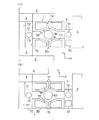
図12(a)に示すように、検査装置4と第2のIFユニット5を基板処理部80のインデクサ部70と反対側の側部側に配置してもよい。この場合には、第2のIFユニット5内の基板受渡しロボット51との間の基板Wの受渡しは、処理部用基板搬送ロボット81が行う。また、この構成では、受渡し用搬送路71の一方の端部側にのみ、露光装置2と第1のIFユニット3を配置してもよいが、図12(a)に示すように、受渡し用搬送路71の両方の端部側にそれぞれ、露光装置2と第1のIFユニット3を配置してもよい。図12(a)に示すように構成すれば、露光処理を2台の露光装置2に振り分けて行うことができる。また、図12(b)に示すように、露光装置2と第1のIFユニット3を基板処理部80のインデクサ部70と反対側の側部側に配置してもよい。   As shown in FIG. 12A, the inspection device 4 and the second IF unit 5 may be arranged on the side of the substrate processing unit 80 opposite to the indexer unit 70. In this case, the processing unit substrate transfer robot 81 transfers the substrate W to and from the substrate transfer robot 51 in the second IF unit 5. Further, in this configuration, the exposure device 2 and the first IF unit 3 may be arranged only on one end side of the transfer path 71 for transfer, but as shown in FIG. The exposure device 2 and the first IF unit 3 may be arranged on both ends of the transport path 71, respectively. With the configuration shown in FIG. 12A, the exposure processing can be distributed to two exposure apparatuses 2. Further, as shown in FIG. 12B, the exposure apparatus 2 and the first IF unit 3 may be arranged on the side of the substrate processing unit 80 opposite to the indexer unit 70.

また、検査装置4が、受渡し用基板搬送ロボット73(第1、第2実施例の場合)や、第5基板搬送ロボット95(第3実施例の場合)、処理部用基板搬送ロボット81(図12の変形例の場合)と直接に基板Wの受渡しが行えるように構成されている場合には、第2のIFユニット5を省略して、受渡し用搬送路71の端部(第1〜第3実施例の場合)や、基板処理部80のインデクサ部70と反対側の側部側(図12の変形例の場合)に隣接して検査装置4を配置するように構成してもよい。露光装置2についても同様に、露光装置2が、受渡し用基板搬送ロボット73(第1、第2実施例の場合)や、第6基板搬送ロボット96(第3実施例の場合)、処理部用基板搬送ロボット81(図12の変形例の場合)と直接に基板Wの受渡しが行えるように構成されている場合には、第1のIFユニット3を省略して、受渡し用搬送路71の端部(第1〜第3実施例の場合)や、基板処理部80のインデクサ部70と反対側の側部側(図12の変形例の場合)に隣接して露光装置2を配置するように構成してもよい。   In addition, the inspection device 4 includes a delivery substrate transfer robot 73 (in the first and second embodiments), a fifth substrate transfer robot 95 (in the third embodiment), and a processing unit substrate transfer robot 81 (see FIG. In the case of a configuration in which the transfer of the substrate W can be performed directly with the case of the modified example of the twelfth embodiment, the second IF unit 5 is omitted and the end portion (first to first) of the transfer path 71 for transfer is omitted. The inspection apparatus 4 may be arranged adjacent to the side of the substrate processing unit 80 opposite to the indexer unit 70 (in the case of the modification in FIG. 12). Similarly, the exposure apparatus 2 includes a transfer substrate transfer robot 73 (in the first and second embodiments), a sixth substrate transfer robot 96 (in the third embodiment), When the configuration is such that the substrate W can be directly transferred to and from the substrate transfer robot 81 (in the case of the modified example of FIG. 12), the first IF unit 3 is omitted and the end of the transfer path 71 for transfer is omitted. The exposure apparatus 2 is arranged adjacent to the exposure unit 2 (in the case of the first to third embodiments) or the side of the substrate processing unit 80 opposite to the indexer unit 70 (in the case of the modification of FIG. 12). You may comprise.

本発明の参考例に係る基板処理装置及びその基板処理装置を含む基板処理システムの全体構成を示す平面図である。FIG. 1 is a plan view illustrating an overall configuration of a substrate processing apparatus according to a reference example of the present invention and a substrate processing system including the substrate processing apparatus. 参考例の制御系の構成を示すブロック図である。FIG. 4 is a block diagram illustrating a configuration of a control system of a reference example. 参考例の変形例の構成を示す平面図である。It is a top view showing the composition of the modification of a reference example. 参考例の別の変形例の要部構成を示す平面図である。It is a top view which shows the principal part structure of another modification of a reference example. 参考例のさらに別の変形例の要部構成を示す平面図である。It is a top view which shows the principal part structure of another modification of a reference example. 本発明の第1実施例に係る基板処理装置及びその基板処理装置を含む基板処理システムの全体構成を示す平面図である。FIG. 1 is a plan view illustrating an overall configuration of a substrate processing apparatus according to a first embodiment of the present invention and a substrate processing system including the substrate processing apparatus. 本発明の第2実施例に係る基板処理装置の構成を示す平面図である。It is a top view showing the composition of the substrate processing device concerning a 2nd example of the present invention. 本発明の第3実施例に係る基板処理装置の要部であるインデクサ部の構成を示す平面図である。FIG. 11 is a plan view illustrating a configuration of an indexer unit that is a main part of a substrate processing apparatus according to a third embodiment of the present invention. 第3実施例に係る基板処理装置のインデクサ部を第1のIFユニット側から見た縦断面図である。FIG. 13 is a vertical cross-sectional view of an indexer unit of a substrate processing apparatus according to a third embodiment as viewed from a first IF unit side. 第3実施例に係る基板処理装置のインデクサ部を基板処理部側から見た縦断面図である。FIG. 13 is a vertical cross-sectional view of an indexer unit of the substrate processing apparatus according to the third embodiment as viewed from the substrate processing unit side. 第2〜第4基板搬送ロボットの構成を示す斜視図である。It is a perspective view showing the composition of the 2nd-4th substrate conveyance robot. 第1〜第3実施例の変形例の構成を示す平面図である。It is a top view showing the composition of the modification of a 1st-3rd example.

符号の説明Explanation of reference numerals

1:基板処理装置
2:露光装置
3:第1のインターフェースユニット
4:検査装置
5:第2のインターフェースユニット
12〜15、TP:熱処理ユニット
16:レジスト塗布処理ユニット
17:現像処理ユニット
71:受渡し用搬送路
73:受渡し用基板搬送ロボット
74:カセット
80:基板処理部
81:処理部用基板搬送ロボット
91〜96:第1〜第6基板搬送ロボット
W:基板
1: substrate processing apparatus 2: exposure apparatus 3: first interface unit 4: inspection apparatus 5: second interface unit 12 to 15, TP: heat treatment unit 16: resist coating processing unit 17: development processing unit 71: delivery Transfer path 73: Transferring substrate transfer robot 74: Cassette 80: Substrate processing unit 81: Processing unit substrate transfer robot 91 to 96: First to sixth substrate transfer robot W: Substrate

Claims (2)

所定方向に延びた受渡し用搬送路と、前記受渡し用搬送路のその一方の側部側に配置されたカセット載置台と、前記受渡し用搬送路に設けられた受渡し用基板搬送ロボットとを含んだインデクサ部と、
露光処理で基板に焼き付けられたパターンを得る現像処理を行う現像処理ユニットと、熱処理を行う熱処理ユニットと、これらの処理ユニットに対して基板を搬送する処理部用基板搬送ロボットとを含み、前記インデクサ部の前記受渡し用搬送路の他方の側部側に配置された基板処理部と、
現像処理で得られたパターンに関する所定の検査を行う検査装置とを備え、
前記検査装置は、前記インデクサ部の前記受渡し用搬送路の端部に配置されていることを特徴とする基板処理装置。
A transfer path extending in a predetermined direction, a cassette mounting table arranged on one side of the transfer path, and a transfer substrate transfer robot provided in the transfer path. Indexer part,
A developing unit for performing a developing process for obtaining a pattern printed on the substrate by the exposure process, a thermal processing unit for performing a thermal process, and a substrate transport robot for a processing unit configured to transport the substrate to these processing units; A substrate processing unit disposed on the other side of the transfer path for the unit,
An inspection device for performing a predetermined inspection on the pattern obtained by the development process,
The substrate processing apparatus, wherein the inspection device is disposed at an end of the delivery path of the indexer unit.
前記検査装置は、前記受渡し用基板搬送ロボットと直接に基板を受渡しすることを特徴とする請求項1に記載の基板処理装置。
2. The substrate processing apparatus according to claim 1, wherein the inspection device transfers the substrate directly to the transfer substrate transfer robot.
JP2004092101A 2004-03-26 2004-03-26 Substrate processing equipment Expired - Fee Related JP4027334B2 (en)

Priority Applications (1)

Application Number Priority Date Filing Date Title
JP2004092101A JP4027334B2 (en) 2004-03-26 2004-03-26 Substrate processing equipment

Applications Claiming Priority (1)

Application Number Priority Date Filing Date Title
JP2004092101A JP4027334B2 (en) 2004-03-26 2004-03-26 Substrate processing equipment

Related Parent Applications (1)

Application Number Title Priority Date Filing Date
JP35270897A Division JP4026906B2 (en) 1997-12-22 1997-12-22 Substrate processing apparatus and substrate processing system

Publications (2)

Publication Number Publication Date
JP2004200726A true JP2004200726A (en) 2004-07-15
JP4027334B2 JP4027334B2 (en) 2007-12-26

Family

ID=32768333

Family Applications (1)

Application Number Title Priority Date Filing Date
JP2004092101A Expired - Fee Related JP4027334B2 (en) 2004-03-26 2004-03-26 Substrate processing equipment

Country Status (1)

Country Link
JP (1) JP4027334B2 (en)

Cited By (4)

* Cited by examiner, † Cited by third party
Publication number Priority date Publication date Assignee Title
WO2008117903A1 (en) * 2007-03-26 2008-10-02 Gun Hwan Kim Apparatus for inspecting wafer and method therefor
JP2009140971A (en) * 2007-12-03 2009-06-25 Tokyo Ohka Kogyo Co Ltd Peeling device
JP2014103412A (en) * 2014-01-17 2014-06-05 Sokudo Co Ltd Substrate processing method and substrate processing device
US9032977B2 (en) 2009-03-18 2015-05-19 Screen Semiconductor Solutions Co., Ltd. Substrate processing method

Citations (5)

* Cited by examiner, † Cited by third party
Publication number Priority date Publication date Assignee Title
JPH0774084A (en) * 1993-09-03 1995-03-17 Canon Inc Substrate processing equipment
JPH07245285A (en) * 1994-03-03 1995-09-19 Dainippon Screen Mfg Co Ltd Substrate processing equipment
JPH0883750A (en) * 1994-09-12 1996-03-26 Nikon Corp Substrate processing equipment
JPH0945613A (en) * 1995-07-28 1997-02-14 Tokyo Electron Ltd Processing equipment
JPH0992702A (en) * 1995-09-27 1997-04-04 Dainippon Screen Mfg Co Ltd Substrate storage cassette, interface mechanism and substrate processing device

Patent Citations (5)

* Cited by examiner, † Cited by third party
Publication number Priority date Publication date Assignee Title
JPH0774084A (en) * 1993-09-03 1995-03-17 Canon Inc Substrate processing equipment
JPH07245285A (en) * 1994-03-03 1995-09-19 Dainippon Screen Mfg Co Ltd Substrate processing equipment
JPH0883750A (en) * 1994-09-12 1996-03-26 Nikon Corp Substrate processing equipment
JPH0945613A (en) * 1995-07-28 1997-02-14 Tokyo Electron Ltd Processing equipment
JPH0992702A (en) * 1995-09-27 1997-04-04 Dainippon Screen Mfg Co Ltd Substrate storage cassette, interface mechanism and substrate processing device

Cited By (5)

* Cited by examiner, † Cited by third party
Publication number Priority date Publication date Assignee Title
WO2008117903A1 (en) * 2007-03-26 2008-10-02 Gun Hwan Kim Apparatus for inspecting wafer and method therefor
JP2009140971A (en) * 2007-12-03 2009-06-25 Tokyo Ohka Kogyo Co Ltd Peeling device
US8186410B2 (en) 2007-12-03 2012-05-29 Tokyo Ohka Kogyo Co., Ltd. Separating device
US9032977B2 (en) 2009-03-18 2015-05-19 Screen Semiconductor Solutions Co., Ltd. Substrate processing method
JP2014103412A (en) * 2014-01-17 2014-06-05 Sokudo Co Ltd Substrate processing method and substrate processing device

Also Published As

Publication number Publication date
JP4027334B2 (en) 2007-12-26

Similar Documents

Publication Publication Date Title
JP2867194B2 (en) Processing device and processing method
TWI447837B (en) Substrate processing device
KR100618108B1 (en) Substrate processing apparatus
JPH1084029A (en) Processing system
CN101819921B (en) Substrate processing apparatus
US8002511B2 (en) Batch forming apparatus, substrate processing system, batch forming method, and storage medium
JPH1092733A (en) Processing system
JP4440178B2 (en) Substrate transfer device
CN217544546U (en) Substrate processing apparatus
CN101978488B (en) Control device and control method
JP4026906B2 (en) Substrate processing apparatus and substrate processing system
KR100188453B1 (en) Device for conveying and loading the object to be processed
CN116804827B (en) Substrate processing apparatus and substrate processing method
JP2013069874A (en) Substrate processing system, substrate transfer method, program and computer storage medium
JP4083371B2 (en) Substrate processing equipment
JP4027334B2 (en) Substrate processing equipment
JP4142702B2 (en) Substrate processing apparatus and substrate processing system
JP4515331B2 (en) Substrate processing system
JP7133451B2 (en) Substrate processing equipment
JP2022083851A (en) Substrate processing device, substrate processing method and storage medium
JP2000200822A (en) Processing system
JP3612265B2 (en) Coating and developing equipment
JP5661584B2 (en) Substrate processing system, substrate transfer method, program, and computer storage medium
JP2022029637A (en) Substrate processing device and transfer schedule creation method
JP3725069B2 (en) Substrate processing system

Legal Events

Date Code Title Description
A131 Notification of reasons for refusal

Free format text: JAPANESE INTERMEDIATE CODE: A131

Effective date: 20070403

A521 Request for written amendment filed

Free format text: JAPANESE INTERMEDIATE CODE: A523

Effective date: 20070604

TRDD Decision of grant or rejection written
A01 Written decision to grant a patent or to grant a registration (utility model)

Free format text: JAPANESE INTERMEDIATE CODE: A01

Effective date: 20071009

A61 First payment of annual fees (during grant procedure)

Free format text: JAPANESE INTERMEDIATE CODE: A61

Effective date: 20071009

FPAY Renewal fee payment (event date is renewal date of database)

Free format text: PAYMENT UNTIL: 20101019

Year of fee payment: 3

R150 Certificate of patent or registration of utility model

Free format text: JAPANESE INTERMEDIATE CODE: R150

FPAY Renewal fee payment (event date is renewal date of database)

Free format text: PAYMENT UNTIL: 20101019

Year of fee payment: 3

FPAY Renewal fee payment (event date is renewal date of database)

Free format text: PAYMENT UNTIL: 20101019

Year of fee payment: 3

FPAY Renewal fee payment (event date is renewal date of database)

Free format text: PAYMENT UNTIL: 20111019

Year of fee payment: 4

FPAY Renewal fee payment (event date is renewal date of database)

Free format text: PAYMENT UNTIL: 20111019

Year of fee payment: 4

FPAY Renewal fee payment (event date is renewal date of database)

Free format text: PAYMENT UNTIL: 20121019

Year of fee payment: 5

FPAY Renewal fee payment (event date is renewal date of database)

Free format text: PAYMENT UNTIL: 20121019

Year of fee payment: 5

FPAY Renewal fee payment (event date is renewal date of database)

Free format text: PAYMENT UNTIL: 20131019

Year of fee payment: 6

R250 Receipt of annual fees

Free format text: JAPANESE INTERMEDIATE CODE: R250

LAPS Cancellation because of no payment of annual fees