JP2004200799A - Image processing apparatus, image processing method, and image processing program - Google Patents
Image processing apparatus, image processing method, and image processing program Download PDFInfo
- Publication number
- JP2004200799A JP2004200799A JP2002364218A JP2002364218A JP2004200799A JP 2004200799 A JP2004200799 A JP 2004200799A JP 2002364218 A JP2002364218 A JP 2002364218A JP 2002364218 A JP2002364218 A JP 2002364218A JP 2004200799 A JP2004200799 A JP 2004200799A
- Authority
- JP
- Japan
- Prior art keywords
- error diffusion
- image
- edge degree
- input
- edge
- Prior art date
- Legal status (The legal status is an assumption and is not a legal conclusion. Google has not performed a legal analysis and makes no representation as to the accuracy of the status listed.)
- Pending
Links
Images





Landscapes
- Facsimile Image Signal Circuits (AREA)
Abstract
Description
【0001】
【発明の属する技術分野】
本発明は、画像処理装置、画像処理方法及び画像処理プログラムに関し、特に、誤差拡散法を用いたN値化処理の技術に関する。
【0002】
【従来の技術】
従来、スキャナ等により入力された画像にモアレ現象が現われたり、またそのスキャン画像に中間調処理を行うとモアレ現象が現われるケースは多い。そもそもモアレ現象とは、スキャナなどにより取り込まれた情報をディジタル的な信号に置き換える際、解像方向や階調方向に情報欠落が生じるため、原稿の画像が持つ周波数やサンプリング周波数や中間調処理の周波数などが干渉を起こし、モアレ現象を引き起こしてしまう。
【0003】
スキャン画像(M値)に対して単純N値化(N<M)を行うとモアレ現象の発生が顕著に現われるが、これは単純N値化により階調方向に対応する濃度情報が欠落されてしまったためである。スキャン画像(M値)に対して中間調再現する方法に誤差拡散法がある。N値化に誤差拡散法を用いると、比較的にモアレ現象を抑制することができる。この理由は、誤差拡散法によって画像全体の濃度情報が保存されるためである。しかし、このように誤差拡散法を用いることでモアレ現象の抑制効果がみられる場合もあるが、一般的にモアレ現象を防止することはできなかった。
【0004】
そこで、特許文献1記載の誤差拡散方法は、スキャン画像データにノイズを付加することで、モアレ現象の低減を狙ったものがある。この特許文献1記載の誤差拡散法は、エッジ検出器にて入力された画像データのエッジを検出し、エッジ検出の結果にしたがって、ノイズレベル決定部にて画像データにノイズを付加して、ノイズ付加画像データを生成し、誤差拡散処理ブロックにて誤差拡散を実施する際に、ノイズ付加画像データにしたがって、誤差拡散を変更して、誤差拡散データを生成し、生成した誤差拡散データから出力画像を生成して、モアレを防止するというものである。
【0005】
また、他の従来技術として、特許文献2記載の2値化処理法が提案されている。この特許文献2記載の2値化処理方法は、画像を構成する連続した画素毎の濃度データを順次読取り、読取られた濃度データに誤差拡散法を適用することによって、画像から2値化された画像データを得る2値化処理方法において、読取られた画像データに対して誤差拡散処理を施すために用いられる誤差拡散マトリクスの内容を注目画素にしたがって変化させることにより、画像のエッジ付近の粒状性ノイズを抑制するというものである。
【0006】
【特許文献1】
特開2001−136388号公報
【特許文献2】
特開平5−300373号公報
【発明が解決しようとする課題】
しかしながら、特許文献1記載の誤差拡散法は、誤差ノイズを付加することで、画質面において粒状性が著しく低下し、孤立ノイズも現われ、入力画像とは異なる質感を再現してしまうという問題がある。
【0007】
また、特許文献2記載の2値化処理方法の処理内容は、画像データが白レベルから黒レベルに変化するとき、特に白レベルから黒レベルに変化する直前に誤差拡散法における誤差伝播マトリックス内容を変化させてエッジ部に余分なドットを打たないようにするというものである。従って、目的はモアレ現象の抑制にかかわるものではなく、処理内容もモアレ現象の抑制に効果は期待できない。
【0008】
また、スキャン画像(M値)に対して誤差拡散法を用いてN値化する場合、画像全体の濃度情報の保存を実現しているが、モアレ現象が発生してしまうという問題がある。
【0009】
そこで、本発明は上記問題点を解決するために、モアレ現象を抑制できるとともに、鮮鋭度も保持し孤立点も抑制できる画像処理装置、画像処理方法及び画像処理プログラムを提供することを目的とする。
【0010】
【課題を解決するための手段】
上記課題を解決するために、請求項1記載の画像処理装置は、画像を入力する画像入力手段と、該画像入力手段により入力された入力画像の所定領域のエッジ度を抽出するエッジ度抽出手段と、該エッジ度抽出手段により抽出されたエッジ度を参照して誤差拡散マトリックスを変更し、変更した誤差拡散マトリックスに基づいて、前記入力画像をN値化する誤差拡散手段と、を有することを特徴とする。
【0011】
請求項1記載の発明によれば、エッジ度抽出手段により抽出されたエッジ度を参照して誤差拡散マトリックスを変更し、変更した誤差拡散マトリックスに基づいて、入力画像をN値化するようにしたので、周期性のあるパターン画像領域、例えば、モアレ現象の発生しやすいパターン画像領域のエッジ部分に対して濃度情報の保存傾向を高めることが出来、モアレ現象を抑制できる。また、粒状性を保持することが可能であり、また鮮鋭度をも保持することが出来、孤立点も抑制できる。
【0012】
また、請求項2記載のように、請求項1の画像処理装置において、前記誤差拡散手段は、前記エッジ度抽出手段により抽出されたエッジ度が大きい場合には、サイズの小さい誤差拡散マトリックスに変更することを特徴とする。請求項2記載の発明によれば、誤差拡散マトリックスサイズを小さくするようにしたので、誤差拡散をエッジ部分のより近辺に拡散させることができる。これにより、モアレ現象を抑制できる。
【0013】
また、請求項3記載のように、請求項1又は2記載の画像処理装置において、前記誤差拡散手段は、前記エッジ度抽出手段により抽出されたエッジ度が大きい場合には、注目画素からの距離の短い周辺画素に大きな係数が配置された誤差拡散マトリックスに変更することを特徴とする。請求項3記載の発明によれば、注目画素からの距離の短い周辺画素からの距離の短い周辺画素に大きな係数が配置された誤差拡散マトリックスに変更するようにしたので、誤差拡散をエッジ部分のより周辺に拡散させることができる。これにより、モアレ現象を抑制できる。
【0014】
また、請求項4記載のように、請求項1から3のいずれか一項に記載の画像処理装置において、前記エッジ度抽出手段は、前記入力画像の所定領域におけるエッジの分布度を抽出することを特徴とする。請求項4記載の発明によれば、入力画像の所定領域におけるエッジの分布度を抽出して、誤差拡散マトリックスを変更するようにしている。
【0015】
また、請求項5記載の画像処理装置は、画像を入力する画像入力手段と、該画像入力手段により入力された入力画像の所定領域の輪郭方向を抽出する輪郭方向抽出手段と、該輪郭方向抽出手段により抽出された輪郭方向を参照して誤差拡散マトリックスを変更し、変更した該誤差拡散マトリックスに基づいて、前記入力画像をN値化する誤差拡散手段と、を有することを特徴とする。
【0016】
請求項5記載の発明によれば、輪郭方向抽出手段により抽出された輪郭方向を参照して誤差拡散マトリックスを変更し、変更した該誤差拡散マトリックスに基づいて、前記入力画像をN値化するようにしたので、モアレ現象の発生しやすいパターン画像領域のエッジ部分において、その輪郭方向に誤差を拡散させることが出来る。つまり、注目画素で発生した誤差を注目画素を含む注目クラスタの輪郭部分に拡散させる。これにより、注目クラスタの濃度情報を保存する傾向を高めることが出来、言い換えると局所領域の濃度情報の保存度合いを高めることが出来るため、よってモアレ現象を抑制できる。また、粒状性を保持することが可能であり、また鮮鋭度をも保持することが出来、孤立点も抑制できる。ここで、クラスタとは、パターンを構成する塊のことであり、網点型パターンにおいてはドット、万線型パターンにおいてはラインを示す。
【0017】
また、請求項6記載のように、請求項5記載の画像処理装置において、前記誤差拡散手段は、前記輪郭方向抽出手段により抽出された輪郭方向に高い割合で誤差を拡散させる誤差拡散マトリックスに変更することを特徴とする。請求項6記載の発明によれば、輪郭方向抽出手段により抽出された輪郭方向に高い割合で誤差を拡散させる誤差拡散マトリックスに変更するようにしたので、モアレ現象の発生しやすいパターン画像領域のエッジ部分において、その輪郭方向に誤差を拡散させることが出来る。これにより、モアレ現象を抑制できる。
【0018】
また、請求項7記載のように、請求項5記載の画像処理装置において、前記輪郭方向抽出手段は、複数の輪郭方向の候補を抽出し、前記誤差拡散手段は、前記輪郭方向抽出手段により抽出した前記複数の輪郭方向候補を参照して誤差拡散マトリックスを変更することを特徴とする。請求項7記載の発明によれば、誤差拡散手段は、輪郭方向抽出手段が抽出した複数の輪郭方向候補を参照して、誤差拡散マトリックスを変更して、モアレ現象の発生しやすいパターン画像領域のエッジ部分において、その輪郭方向に誤差を拡散させるようにしている。これにより、モアレ現象を抑制できる。
【0019】
また、請求項8記載のように、請求項5から7のいずれか一項に記載の画像処理装置において、前記誤差拡散手段は、処理順序方向を参照して、誤差拡散マトリックスを変更することを特徴とする。請求項8記載の発明によれば、誤差拡散手段は、処理順序方向を参照して、誤差拡散マトリックスを変更して、モアレ現象の発生しやすいパターン画像領域のエッジ部分において、その輪郭方向に誤差を拡散させるようにしている。これにより、モアレ現象を抑制できる。
【0020】
また、請求項9記載のように、請求項5から8のいずれか一項に記載の画像処理装置において、前記誤差拡散手段は、前記輪郭方向抽出手段により、輪郭方向が不明又は輪郭が無いと判断された場合に、所定の誤差拡散マトリックスを使用することを特徴とする。請求項9記載の発明によれば、誤差拡散手段は、輪郭方向抽出手段により輪郭方向が不明又は輪郭が無いと判断された場合に、所定の誤差拡散マトリックスを使用するようにしているので、エッジ部分以外は、所定の誤差拡散マトリックスを使用することにより、滑らかな中間調再現が可能となる。
【0021】
また、請求項10記載の画像処理装置は、画像を入力する画像入力手段と、該画像入力手段により入力された入力画像の所定領域のエッジ度を抽出するエッジ度抽出手段と、該エッジ度抽出手段により抽出されたエッジ度を参照して、誤差拡散マトリックスの係数に乗算する伝播率係数を変更し、変更した該伝播係数を用いて、前記入力画像をN値化する誤差拡散手段と、を有することを特徴とする。
【0022】
請求項10記載の発明によれば、エッジ度抽出手段により抽出されたエッジ度を参照して、誤差拡散マトリックスの係数に乗算する伝播率係数を変更し、変更した伝播係数を用いて、入力画像をN値化するようにしたので、入力画像において他領域や他クラスタで生じた誤差が伝播されてきて注目クラスタや注目画素に不要な誤差として計上され処理されることを防ぐことが可能である。つまり、注目している局所領域の濃度情報の保存度合いを高めることが出来るため、モアレ現象を抑制できる。また、粒状性を保持することが可能であり、また鮮鋭度をも保持することが出来、孤立点も抑制できる。
【0023】
また、請求項11記載のように、請求項10記載の画像処理装置において、前記エッジ度抽出手段は、前記入力画像の所定領域におけるエッジの分布度を抽出することを特徴とする。請求項11記載の発明によれば、入力画像の所定領域におけるエッジの分布度を抽出して、伝播係数を変更するようにしている。これにより、モアレ現象を抑制できる。
【0024】
また、請求項12記載の画像処理装置は、請求項10又は11記載の画像処理装置において、更に、前記入力画像の所定領域の濃度を抽出する濃度抽出手段を有し、前記誤差拡散手段は、該濃度抽出手段により抽出された所定領域の濃度に基づいて、誤差拡散マトリックスの係数に乗算する伝播率係数を変更することを特徴とする。請求項12記載の発明によれば、濃度抽出手段により抽出された所定領域の濃度に基づいて、誤差拡散マトリックスの係数に乗算する伝播係数を変更するようにして、注目画素とは関係ない他領域からの誤差を低減させるようにしている。これにより、モアレ現象を抑制できる。
【0025】
また、請求項13記載のように、請求項1から12のいずれか一項に記載の画像処理装置において、前記N値化は、2値化であることを特徴とする。
【0026】
また、請求項14記載の画像処理方法は、画像を入力する画像入力段階と、該画像入力段階により入力された入力画像の所定領域のエッジ度を抽出するエッジ度抽出段階と、該エッジ度抽出段階により抽出されたエッジ度を参照して誤差拡散マトリックスを変更し、変更した誤差拡散マトリックスに基づいて、前記入力画像をN値化する誤差拡散段階と、を有することを特徴とする。
【0027】
請求項14記載の発明によれば、エッジ度抽出段階により抽出されたエッジ度を参照して誤差拡散マトリックスを変更し、変更した誤差拡散マトリックスに基づいて、入力画像をN値化するようにしたので、周期性のあるパターン画像領域、例えば、モアレ現象の発生しやすいパターン画像領域のエッジ部分に対して濃度情報の保存傾向を高めることが出来、モアレ現象を抑制できる。また、粒状性を保持することが可能であり、また鮮鋭度をも保持することが出来、孤立点も抑制できる。
【0028】
また、請求項15記載のように、請求項14の画像処理方法において、前記誤差拡散段階は、前記エッジ度抽出段階により抽出されたエッジ度が大きい場合には、サイズの小さい誤差拡散マトリックスに変更することを特徴とする。請求項15記載の発明によれば、誤差拡散マトリックスサイズを小さくするようにしたので、誤差拡散をエッジ部分のより近辺に拡散させることができる。これにより、モアレ現象を抑制できる。
【0029】
また、請求項16記載のように、請求項14又は15記載の画像処理方法において、前記誤差拡散段階は、前記エッジ度抽出段階により抽出されたエッジ度が大きい場合には、注目画素からの距離の短い周辺画素に大きな係数が配置された誤差拡散マトリックスに変更することを特徴とする。請求項16記載の発明によれば、注目画素からの距離の短い周辺画素からの距離の短い周辺画素に大きな係数が配置された誤差拡散マトリックスに変更するようにしたので、誤差拡散をエッジ部分のより周辺に拡散させることができる。これにより、モアレ現象を抑制できる。
【0030】
また、請求項17記載の画像処理方法は、画像を入力する画像入力段階と、該画像入力段階により入力された入力画像の所定領域の輪郭方向を抽出する輪郭方向抽出段階と、該輪郭方向抽出段階により抽出された輪郭方向を参照して誤差拡散マトリックスを変更し、変更した該誤差拡散マトリックスに基づいて、前記入力画像をN値化する誤差拡散段階と、を有することを特徴とする。
【0031】
請求項17記載の発明によれば、輪郭方向抽出段階により抽出された輪郭方向を参照して誤差拡散マトリックスを変更し、変更した該誤差拡散マトリックスに基づいて、前記入力画像をN値化するようにしたので、モアレ現象の発生しやすいパターン画像領域のエッジ部分において、その輪郭方向に誤差を拡散させることが出来る。つまり、注目画素で発生した誤差を注目画素を含む注目クラスタの輪郭部分に拡散させる。これにより、注目クラスタの濃度情報を保存する傾向を高めることが出来、言い換えると局所領域の濃度情報の保存度合いを高めることが出来るため、よってモアレ現象を抑制できる。また、粒状性を保持することが可能であり、また鮮鋭度をも保持することが出来、孤立点も抑制できる。
【0032】
また、請求項18記載の画像処理方法は、画像を入力する画像入力段階と、該画像入力段階により入力された入力画像の所定領域のエッジ度を抽出するエッジ度抽出段階と、該エッジ度抽出段階により抽出されたエッジ度を参照して、誤差拡散マトリックスの係数に乗算する伝播率係数を変更し、変更した該伝播係数を用いて、前記入力画像をN値化する誤差拡散段階と、を有することを特徴とする。
【0033】
請求項18記載の発明によれば、エッジ度抽出段階により抽出されたエッジ度を参照して、誤差拡散マトリックスの係数に乗算する伝播率係数を変更し、変更した伝播係数を用いて、入力画像をN値化するようにしたので、入力画像において他領域や他クラスタで生じた誤差が伝播されてきて注目クラスタや注目画素に不要な誤差として計上され処理されることを防ぐことが可能である。つまり、注目している局所領域の濃度情報の保存度合いを高めることが出来るため、モアレ現象を抑制できる。また、粒状性を保持することが可能であり、また鮮鋭度をも保持することが出来、孤立点も抑制できる。
【0034】
また、請求項19記載の画像処理プログラムは、画像入力手段から入力された入力画像を処理するためにコンピュータを、前記入力画像の所定領域のエッジ度を抽出するエッジ度抽出手段、該エッジ度抽出手段により抽出されたエッジ度を参照して誤差拡散マトリックスを変更し、変更した誤差拡散マトリックスに基づいて、前記入力画像をN値化する誤差拡散手段として機能させる。
【0035】
請求項19記載の発明によれば、エッジ度抽出手段により抽出されたエッジ度を参照して誤差拡散マトリックスを変更し、変更した誤差拡散マトリックスに基づいて、入力画像をN値化するようにしたので、周期性のあるパターン画像領域、例えば、モアレ現象の発生しやすいパターン画像領域のエッジ部分に対して濃度情報の保存傾向を高めることが出来、モアレ現象を抑制できる。また、粒状性を保持することが可能であり、また鮮鋭度をも保持することが出来、孤立点も抑制できる。
【0036】
また、請求項20記載のように、請求項19の画像処理プログラムにおいて、前記誤差拡散手段は、前記エッジ度抽出手段により抽出されたエッジ度が大きい場合には、サイズの小さい誤差拡散マトリックスに変更することを特徴とする。請求項20記載の発明によれば、誤差拡散マトリックスサイズを小さくするようにしたので、誤差拡散をエッジ部分のより近辺に拡散させることができる。これにより、モアレ現象を抑制できる。
【0037】
また、請求項21記載のように、請求項19又は20記載の画像処理プログラムにおいて、前記誤差拡散手段は、前記エッジ度抽出手段により抽出されたエッジ度が大きい場合には、注目画素からの距離の短い周辺画素に大きな係数が配置された誤差拡散マトリックスに変更することを特徴とする。請求項21記載の発明によれば、注目画素からの距離の短い周辺画素からの距離の短い周辺画素に大きな係数が配置された誤差拡散マトリックスに変更するようにしたので、誤差拡散をエッジ部分のより周辺に拡散させることができる。これにより、モアレ現象を抑制できる。
【0038】
また、請求項22記載の画像処理プログラムは、画像入力手段から入力された入力画像を処理するためにコンピュータを、前記入力画像の所定領域の輪郭方向を抽出する輪郭方向抽出手段、該輪郭方向抽出手段により抽出された輪郭方向を参照して誤差拡散マトリックスを変更し、変更した該誤差拡散マトリックスに基づいて、前記入力画像をN値化する誤差拡散手段として機能させる。
【0039】
請求項22記載の発明によれば、輪郭方向抽出手段により抽出された輪郭方向を参照して誤差拡散マトリックスを変更し、変更した該誤差拡散マトリックスに基づいて、前記入力画像をN値化するようにしたので、モアレ現象の発生しやすいパターン画像領域のエッジ部分において、その輪郭方向に誤差を拡散させることが出来る。つまり、注目画素で発生した誤差を注目画素を含む注目クラスタの輪郭部分に拡散させる。これにより、注目クラスタの濃度情報を保存する傾向を高めることが出来、言い換えると局所領域の濃度情報の保存度合いを高めることが出来るため、よってモアレ現象を抑制できる。また、粒状性を保持することが可能であり、また鮮鋭度をも保持することが出来、孤立点も抑制できる。
【0040】
また、請求項23記載の画像処理プログラムは、画像入力手段から入力された入力画像を処理するためにコンピュータを、前記入力画像の所定領域のエッジ度を抽出するエッジ度抽出手段、該エッジ度抽出手段により抽出されたエッジ度を参照して、誤差拡散マトリックスの係数に乗算する伝播率係数を変更し、変更した該伝播係数を用いて、前記入力画像をN値化する誤差拡散手段として機能させる。
【0041】
請求項23記載の発明によれば、エッジ度抽出手段により抽出されたエッジ度を参照して、誤差拡散マトリックスの係数に乗算する伝播率係数を変更し、変更した伝播係数を用いて、入力画像をN値化するようにしたので、入力画像において他領域や他クラスタで生じた誤差が伝播されてきて注目クラスタや注目画素に不要な誤差として計上され処理されることを防ぐことが可能である。つまり、注目している局所領域の濃度情報の保存度合いを高めることが出来るため、モアレ現象を抑制できる。また、粒状性を保持することが可能であり、また鮮鋭度をも保持することが出来、孤立点も抑制できる。
【0042】
【発明の実施の形態】
(第1の実施の形態)
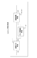
図1は、第1の実施の形態に係る画像処理装置を説明するための図である。
図1に示すように、画像処理装置10は、画像入力手段11と、エッジ度抽出手段12と、誤差拡散手段13とを有する。
【0043】
画像入力手段11は、スキャンイン画像A1を入力し、入力された入力画像B1をエッジ度抽出手段12と、誤差拡散手段13に出力する。エッジ度抽出手段12は、画像入力手段11からの入力画像B1に対して所定領域のエッジ度を抽出し、抽出した所定領域のエッジ度を誤差拡散手段13に出力する。ここで所定領域は入力画面における任意の領域のことである。また、エッジ度抽出手段12は、入力画像の所定領域におけるエッジの分布度を抽出するようにしてもよい。
【0044】
誤差拡散手段13は、エッジ度抽出手段12が抽出したエッジ度を参照して、画像入力手段11からの入力画像B1を誤差拡散法によりN値化を行う。なお、誤差拡散手段13により行われるN値化は、2値化であってもよい。また、誤差拡散手段は、エッジ度抽出手段12により抽出されたエッジ度が大きい場合には、サイズの小さい誤差拡散マトリックスに変更するようにしてもよい。また、誤差拡散手段13は、エッジ度抽出手段12により抽出されたエッジ度が大きい場合には、注目画素からの距離の短い周辺画素に大きな係数が配置された誤差拡散マトリックスに変更するようにしてもよい。
【0045】
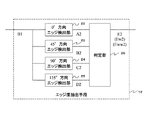
次に、エッジ度抽出手段12について説明する。図2は、エッジ度抽出手段のブロック図である。図2に示すように、エッジ度抽出手段12は、0°方向エッジ検出部22と、45°方向エッジ検出部23と、90°方向エッジ検出部24と、135°方向エッジ検出部25と、判定部26とを有する。
【0046】
0°方向エッジ検出部22と、45°方向エッジ検出部23と、90°方向エッジ検出部24と、135°方向エッジ検出部25は、画像入力手段11から入力された入力画像B1に対して、それぞれの方向のエッジ強度を算出し、判定部26に算出したエッジ強度の出力値A2、B2、C2、D2を出力する。各エッジ方向検出部22、23、24、25は、1次微分値を用いても良いし、2次微分値を用いても良い。各エッジ方向検出部22、23、24、25のエッジ強度の出力値A2、B2、C2、D2は、微分値の絶対値を用いる。
【0047】
判定部26は、各エッジ方向検出器22、23、24、25からのエッジ強度の出力値A2、B2、C2、D2を参照してエッジ強度を判定し、出力値E2を誤差拡散手段13へ出力する。ここで、出力値E2はエッジ強度の判定結果である。
【0048】
判定部26におけるエッジ強度の判定は、各エッジ方向検出部の出力値A2、B2、C2、D2の中から最大値のものをM2とし、M2と閾値T0と閾値T1(T0>T1)とを比較して、
・M2>T0ならば、エッジ度=強Ehとし、
・T0≧M2>T1ならば、エッジ度=中Emとし、
・T1≧M2ならば、エッジ度=弱Elとし、EhとEmとElのいずれかを出力値E2とする。
【0049】
なお、M2は、エッジ方向検出部22、23、24、25の出力値A2、B2、C2、D2の和であっても良い。
【0050】
次に、エッジ度抽出手段の処理について説明する。図3は、エッジ度抽出手段を説明するための図である。図3(a)は、エッジ度抽出手段12への入力画像B1の例を示している。図3(b)は、入力画像B1に対して、上記で求めたエッジ検出部22、23、24、25の出力値の最大値M2または判定部26の出力値E2を画像で表したものである(4方向エッジ検出結果)。また、図3(b)には、0°方向エッジ検出部22、45°方向エッジ検出部23、90°方向エッジ検出部24、135°方向エッジ検出部25の検出箇所を示している。図3(c)は、エッジ強度を判定するときの参照範囲の例をあらわしたものであり、破線内部の領域が参照範囲を示している。また、図中アスタリスク*は、注目画素を示している。なお、所定領域が参照範囲に相当するが、図3には限定されない。
【0051】
判定部26は、この参照範囲内のM2またはE2の和をW2とし、W2と閾値T10と閾値T11(T10>T11)とを比較して、
・W2>T10ならばエッジ度=強Ewhとし、
・T10≧W2>T11ならエッジ度=中Ewmとし、
・T11≧W2ならばエッジ度=弱Ewlとし、
・EwhとEwmとEwlのいずれかを出力値Ew2とする。
【0052】
また、図3(d)は、エッジの分布度を判定するときの参照範囲の例をあらわしたものである。各破線内部の領域が参照範囲を示している。図3(d)において、アスタリスク*は、注目画素を示している。各領域α、β、γ、δそれぞれに対して上記のようにエッジ強度Ew2を求め、求めた値をそれぞれEw2α、Ew2β、Ew2γ、Ew2δとする。
【0053】
次に、エッジ強度Ew2αと閾値T20と閾値T21(T20>T21)とを比較して、
・Ew2α>T20ならばエッジ度=強Ew2αHとし、
・T20≧Ew2α>T21ならエッジ度=中Ew2αmとし、
・T21≧Ew2αならばエッジ度=弱Ew2αlとし、Ew2αhとEw2αmとEw2αlのいずれかを算出値Eww2αとする。
【0054】
Ew2βとEw2γとEw2δに対してもEw2αと同様に算出して、それぞれの算出値をEww2β、Eww2γ、Eww2δとする。そして、Eww2αとEww2βとEww2γとEww2δそれぞれを閾値T30と閾値T31(T30>T31)と閾値T32を比較して、
・Eww2αとEww2βとEww2γとEww2δの中で閾値T32個以上が閾値T30以上の場合は、エッジ分布度=高Ewwhとし、
・それ以外で且つ、Eww2αとEww2βとEww2γとEww2δの中で閾値T32個以上が閾値T31以上の場合は、エッジ分布度=中Ewwmとし、
・それ以外の場合はエッジ分布度=低Ewwlとし、EwwhとEwwmとEwwlのいずれかをエッジ分布度の出力値Eww2とする。このエッジ分布度の出力値Eww2は後述する誤差拡散マトリックス選択部43に入力される。
【0055】
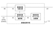
次に、図4及び図5を用いて、誤差拡散手段13について説明する。図4は、図1の誤差拡散手段を説明するための図である。図4に示すように、誤差拡散手段13は、誤差拡散N値化部42と、誤差拡散マトリックス選択部43と、誤差拡散マトリックス記憶部44とを有する。図5は、図4の誤差拡散マトリックス記憶部に格納される誤差拡散マトリックスの例を示す図である。図5において、アスタリスク*は注目画素を示している。
【0056】
図5(a)はサイズの一番小さい誤差拡散マトリックスを示し、(b)は(a)の次にサイズの小さい誤差拡散マトリックスを示し、(c)〜(f)は同じサイズの誤差拡散マトリックスを示している。また、図5(d)、及び(e)は、注目からの距離の短い周辺画素により大きな係数が配置された誤差拡散マトリックスを示している。
・誤差拡散マトリックス選択部43は、エッジ度抽出手段12の判定部26からの出力値E2(またはEw2またはEww2)を参照して、誤差拡散マトリックス記憶部44に記憶されている誤差拡散マトリックスを選択する。
・誤差拡散マトリックス選択部43は、判定部26からの出力値E2(またはEw2またはEww2)がエッジ度強Eh(またはエッジ度強Ewhまたはエッジ分布度強Ewwh)である場合には、図5(a)の誤差拡散マトリックスのようにサイズの小さい誤差拡散マトリックスまたは図5(d)の誤差拡散マトリックスのように注目画素からの距離の短い周辺画素により大きな係数が配置された誤差拡散マトリックスを選択し、
・判定部26からの出力値E2(またはEw2またはEww2)がエッジ度中Em(またはエッジ度中Ewmまたはエッジ分布度中Ewwm)である場合には、図5(b)の誤差拡散マトリックスまたは図5(e)の誤差拡散マトリックスを選択し、
・判定部26からの出力値E2(またはEw2またはEww2)がエッジ度弱El(またはエッジ度弱Ewlまたはエッジ分布度低Ewwl)である場合には、図5(c)の誤差拡散マトリックスまたは図5(f)の誤差拡散マトリックスを選択する。
【0057】
このように、誤差拡散マトリックス選択部43は、抽出エッジ度が強いまたは抽出エッジ分布が高い場合(エッジ度が大きい場合)には、サイズの小さい誤差拡散マトリックスまたは注目画素からの距離の短い周辺画素により大きな係数が配置された誤差拡散マトリックスに変更する。誤差拡散N値化部42は、誤差拡散マトリックス選択部43により選択された誤差拡散マトリックスを用いて、入力画像B1のN値化を行う。
【0058】
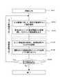
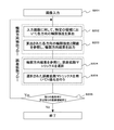
次に、本実施の形態に係る画像処理の動作について説明する。図6は、画像処理のフローチャートを示している。ステップ101において、画像入力手段11に画像が入力される。次に、エッジ度抽出処理に入り、ステップ102において、エッジ度抽出手段12の各エッジ検出部22、23、24、25は、入力画像B1に対して所定領域のエッジ量を算出する。ステップ103において、エッジ度抽出手段12の判定部26は、算出されたエッジ量を閾値と比較参照し、そのエッジ度結果を出力する。
【0059】
次に、誤差拡散処理に入り、ステップ104において、誤差拡散手段13の誤差拡散マトリックス選択部43は、エッジ度結果を参照して、誤差拡散マトリックスを選択する。ステップ105において、誤差拡散手段13の誤差拡散N値化部42は、選択された誤差拡散マトリックスを用いて、入力画像B1のN値化を行う。ステップ106において、残りの画素が有るかどうか又は残りの画素領域が有るかどうかを判断し、残りの画素又は残りの画素領域がある場合には、ステップ102に進む。一方、残りの画素又は残りの画素領域が無い場合には、処理を終了する。
【0060】
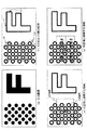
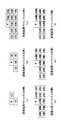
次に、図16を用いて、本実施の形態における効果を説明する。図16は、第1の実施の形態の効果を説明する図である。図16(a)は、(b)(c)で用いる注目画素位置と誤差拡散マトリクスを説明するための図である。アスタリスク*は注目画素位置を示している。また、破線で囲まれた領域は誤差拡散マトリクスを示している。
【0061】
図16(b)は万線クラスタ画像の例を示している。図16(b)のX1に示すように、モアレ現象の発生しやすいパターン画像領域のエッジ部分においては、誤差拡散マトリックスサイズを小さくすることで発生誤差をエッジ部分のより近辺に拡散させることができる。つまり、エッジ部分の局所領域の濃度情報の保存度合いを高めることができるため、モアレ現象を抑制できる。また、図16(b)のX2に示すような従来の大きさの誤差拡散マトリックス(誤差拡散マトリックスサイズ大)は、エッジ部分以外に使用することにより、滑らかな中間調再現が可能となる。
【0062】
図16(c)は網点クラスタ画像の例を示している。図16(c)のX3に示すように、モアレ現象の発生しやすいパターン画像領域のエッジ部分においては、誤差拡散マトリックスサイズを小さくすることで発生誤差をエッジ部分のより近辺に拡散させることができる。つまり、エッジ部分の局所領域の濃度情報の保存度合いを高めることができるため、モアレ現象を抑制できる。また、図16(c)のX4に示すような従来の大きさの誤差拡散マトリックス(誤差拡散マトリックスサイズ大)は、エッジ部分以外に使用することにより、滑らかな中間調再現が可能となる。
【0063】
なお、本実施の形態において、エッジ抽出手段12と誤差拡散手段13については一例を示しており、上記例に限るものではない。
【0064】
(第2の実施の形態)
次に、第2の実施の形態に係る画像処理装置について説明する。図7は、第2の実施形態に係る画像処理装置のブロック図である。図7に示すように、画像処理装置110は、画像入力手段71と、輪郭方向抽出手段72と、誤差拡散手段73とを有する。
【0065】
画像入力手段71は、スキャンイン画像A7を入力し、入力画像B7を輪郭方向検出手段72と、誤差拡散手段73に出力する。輪郭方向抽出手段72は、画像入力手段71からの入力画像B7に対して所定領域の輪郭方向を算出し、算出した所定領域の輪郭方向抽出結果を誤差拡散手段73に出力する。ここで、所定の領域とは、入力画像中の任意の領域のことである。また、輪郭方向抽出手段72は、複数の輪郭方向の候補を抽出するようにしてもよい。
【0066】
誤差拡散手段73は、輪郭方向抽出手段72からの輪郭方向抽出結果を参照して、画像入力手段71からの入力画像B7を誤差拡散法によりN値化を行う。誤差拡散手段73によるN値化は2値化であってもよい。また、誤差拡散手段73は、輪郭方向抽出手段72により抽出された輪郭方向に高い割合で誤差を拡散させる誤差拡散マトリックスに変更するようにしてもよい。また、誤差拡散手段73は、輪郭方向抽出手段72により抽出した複数の輪郭方向候補を参照して誤差拡散マトリックスを変更するようにしてもよい。
【0067】
次に、図8を用いて、輪郭方向抽出手段72を説明する。図8(a)は、輪郭方向抽出手段のブロック図である。なお、図8(b)は誤差拡散処理方向を示しており、詳細は後述する。
【0068】
図8(a)に示すように、輪郭方向抽出手段72は、0°方向輪郭検出部82と、45°方向輪郭検出部83と、90°方向輪郭検出部84と、135°方向輪郭検出部85と、判定部86とを有する。0°方向輪郭検出部82と45°方向輪郭検出部83と90°方向輪郭検出部84と135°方向輪郭検出部85は、画像入力手段71からの入力画像B7に対して、それぞれの方向の輪郭強度を算出する。また、各方向輪郭検出部82、83、84、85は算出した輪郭強度の出力値A8、B8、C8、D8を判定部86に出力する。
【0069】
各輪郭方向検出部82、83、84、85は、1次微分値を用いても良いし、2次微分値を用いても良い。各輪郭方向検出器82、83、84、85のそれぞれの出力値A8、B8、C8、D8は微分値の絶対値を用いる。判定部86は、各輪郭検出部82、83、84、85の出力値A8、B8、C8、D8を参照して、輪郭方向を判定する。
【0070】
判定部86における輪郭方向の判定は、各輪郭検出部82、83、84、85からの出力値A8、B8、C8、D8の中から最大値のものをM8とする。判定部86は、最大値M8と閾値T40と比較してM8>T40ならば輪郭ありと判定し、且つM8に対応する輪郭方向を検出輪郭方向とし、この輪郭方向検出結果E8を出力する。一方、判定部86は、M8≦T40ならば輪郭無しと判定し、この輪郭方向検出結果をE8として出力する。
【0071】
つまり、
・判定部86は、M8≦T40ならば、輪郭方向結果E8=Dnonとし、
・M8>T40かつM8=A8ならば、輪郭方向結果E8=D0とし、
・M8>T40かつM8=B8ならば、輪郭方向結果E8=D45とし、
・M8>T40かつM8=C8ならば、輪郭方向結果E8=D90とし、
・M8>T40かつM8=D8ならば、輪郭方向結果E8=D135とする。
【0072】
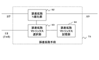
次に、誤差拡散手段について説明する。図9は、図7の誤差拡散手段の一例を示すブロック図である。図9に示すように、誤差拡散手段73は、誤差拡散N値化部92と、誤差拡散マトリックス選択部93と、誤差拡散マトリックス記憶部94とを有する。誤差拡散マトリックス部93は、判定部86からの出力値E8を参照して、誤差拡散マトリックス記憶部94に記憶されている誤差拡散マトリックスを選択する。
【0073】
図10(a)〜(e)は、図9の誤差拡散マトリックス記憶部94に格納される誤差拡散マトリックスの例を示す図である。図10(a)は0°の輪郭方向に誤差を大きい割合で伝播させる誤差拡散マトリックスの例、(b)は45°の輪郭方向に誤差を大きい割合で伝播させる誤差拡散マトリックスの例、(c)は90°の輪郭方向に誤差を大きい割合で伝播させる誤差拡散マトリックスの例、(d)は135°の輪郭方向に誤差を大きい割合で伝播させる誤差拡散マトリックスの例、(e)は通常の誤差拡散マトリックスの例である。
・誤差拡散マトリックス選択部93は、輪郭方向検出結果E8=Dnonならば、図10(e)の誤差拡散マトリックスを選択し、
・輪郭方向検出結果E8=D0ならば、図10(a)の誤差拡散マトリックスを選択し、
・輪郭方向検出結果E8=D45ならば、図10(b)の誤差拡散マトリックスを選択し、
・輪郭方向検出結果E8=D90ならば、図10(c)の誤差拡散マトリックスを選択し、
・輪郭方向検出結果E8=D135ならば、図10(d)の誤差拡散マトリックスを選択する。
【0074】
このように、誤差拡散マトリックス選択部93は、抽出された輪郭方向に誤差を大きい割合で伝播させるような誤差拡散マトリックスを選択する。誤差拡散N値化部92は、誤差拡散マトリックス選択部93により選択された誤差拡散マトリックスを用いて、N値化を行う。
【0075】
次に、上述した図8、図9と、以下に述べる図10を用いて、輪郭方向抽出手段72と誤差拡散手段73の別の例について説明する。まず、図8を用いて、輪郭方向抽出手段72の別の例を説明する。なお、上述した輪郭方向抽出部72と構成は同じで、動作のみ異なる。
【0076】
0°方向輪郭検出部82と、45°方向輪郭検出部83と、90°方向輪郭検出部84と、135°方向輪郭検出部85とでそれぞれの方向の輪郭強度を算出する。各輪郭方向検出部82、83、84、85は、1次微分値を用いても良いし、2次微分値を用いても良い。各輪郭方向検出器82、83、84、85のそれぞれの出力値A8、B8、C8、D8は、微分値の絶対値を用いる。
【0077】
判定部86は、出力値A8、B8、C8、D8を参照して、輪郭方向を判定する。判定部86における輪郭方向の判定は、出力値A8、B8、C8、D8の中で最大値のものと2番目に大きいものをそれぞれMf8、Ms8とし、Mf8と閾値T40と比較する。判定部86は、Mf8≦T40ならば輪郭無し(non)と判定する。一方、判定部86は、Mf8>T40ならば輪郭ありと判定する。判定部86は、輪郭ありと判定した場合は、Mf8とMs8とそれぞれに対応する輪郭方向と誤差拡散処理方向を参照して、判定を行い、輪郭方向結果をEw8として出力する。すなわち、判定部86は複数の輪郭方向の候補を抽出する。
【0078】
誤差拡散処理方向を図8(b)に示す。図8(b)では、ライン処理方向がラインにより異なる例を示している。図8(b)に示すように、入力画像の左から右へ処理する場合をR方向とし、右から左へ処理する場合をL方向とする。具体的な判定を以下に示す。まず、誤差拡散処理方向がR方向の場合においては、
・判定部86は、Mf8≦T40ならば輪郭方向結果Ew8=Drnonとする。
・判定部86は、Mf8>T40かつMf8=A8ならば、Ew8=Dr0とし、
・Mf8>T40かつMf8=B8ならば、輪郭方向結果Ew8=Dr45とし、
・Mf8>T40かつMf8=C8ならば、輪郭方向結果Ew8=Dr90とし、
・Mf8>T40かつMf8=D8ならば、輪郭方向結果Ew8=Dr135とする。
【0079】
但し、
・判定部86は、Mf8>T40かつMf8=A8かつMs8=B8かつMs8×e≧Mf8ならば、輪郭方向検出結果Ew8=Dr45とし、
・Mf8>T40かつMf8=B8かつMs8=C8かつMs8×e≧Mf8ならば、輪郭方向検出結果Ew8=Dr90とし、
・Mf8>T40かつMf8=C8かつMs8=D8かつMs8×e≧Mf8ならば、輪郭方向検出結果Ew8=Dr135とする。
【0080】
また、誤差拡散処理方向が複数あり、R方向とL方向がある場合においては、誤差拡散処理方向がR方向の場合には上記と同様にする。
誤差拡散処理方向がL方向の場合においては、
・判定部86は、Mf8≦T40ならば、輪郭方向結果Ew8=Dlnonとする。
・判定部86は、Mf8>T40かつMf8=A8ならば、輪郭方向結果Ew8=Dl0とし、
・Mf8>T40かつMf8=B8ならば、輪郭方向結果Ew8=Dl45とし、
・Mf8>T40かつMf8=C8ならば、輪郭方向結果Ew8=Dl90とし、
・Mf8>T40かつMf8=D8ならば、輪郭方向結果Ew8=Dl135とする。
【0081】
但し、
・判定部86は、Mf8>T40かつMf8=A8かつMs8=D8かつMs8×e≧Mf8ならば、輪郭方向結果Ew8=Dl135とし、
・Mf8>T40かつMf8=D8かつMs8=C8かつMs8×e≧Mf8ならば、輪郭方向結果Ew8=Dl90とし、
・Mf8>T40かつMf8=C8かつMs8=B8かつMs8×e≧Mf8ならば輪郭方向結果Ew8=Dl45とする。ここで、eは1以上の実数とする。
【0082】
次に、誤差拡散手段73の別の例を再度図9、図10を用いて説明する。図9に示すように、誤差拡散マトリックス選択部93は、Ew8信号を参照にし、誤差拡散マトリックス記憶部94に記憶されている誤差拡散マトリックスを選択する。図10(a)〜(e)は、R方向に処理する場合に選択される誤差拡散マトリックスの例を示し、図10(f)〜(j)は、L方向に処理する場合に選択される誤差拡散マトリックスの例を示している。なお、図10に示す角度は、各角度の輪郭方向に誤差を大きい割合で伝播させる誤差拡散マトリックスを示す。
・誤差拡散マトリックス選択部93は、輪郭方向検出結果Ew8=Drnonならば、図10(e)の誤差拡散マトリックスを選択し、
・輪郭方向検出結果Ew8=Dr0ならば、図10(a)の誤差拡散マトリックスを選択し、
・輪郭方向検出結果Ew8=Dr45ならば、図10(b)の誤差拡散マトリックスを選択し、
・輪郭方向検出結果Ew8=Dr90ならば、図10(c)の誤差拡散マトリックスを選択し、
・輪郭方向検出結果Ew8=Dr135ならば、図10(d)の誤差拡散マトリックスを選択し、
・輪郭方向検出結果Ew8=Dlnonならば、図10(j)の誤差拡散マトリックスを選択し、
・輪郭方向検出結果Ew8=Dl0ならば、図10(f)の誤差拡散マトリックスを選択し、
・輪郭方向検出結果Ew8=Dl45ならば、図10(g)の誤差拡散マトリックスを選択し、
・輪郭方向検出結果Ew8=Dl90ならば、図10(h)の誤差拡散マトリックスを選択し、
・輪郭方向検出結果Ew8=Dl135ならば、図10(i)の誤差拡散マトリックスを選択する。
【0083】
このように、誤差拡散マトリックス93は、輪郭方向の候補方向と誤差拡散処理方向を考慮して、誤差拡散マトリックスを選択する。誤差拡散N値化部92は、選択された誤差拡散マトリックスを用いて、N値化を行う。
【0084】
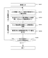
次に、本実施の形態に係る画像処理について説明する。図11は、画像処理の一実施形態を示すフローチャートである。ステップ201において、画像入力手段71に画像が入力される。輪郭方向抽出処理に入り、ステップ202において、輪郭方向抽出手段72の各輪郭検出部82、83、84、85は、入力画像B7に対して所定領域における各方向の輪郭強度を算出する。ステップ203において、輪郭方向抽出手段72の判定部86は、算出された各方向の輪郭強度と閾値を参照し、輪郭方向結果E8(Ew8)を出力する。
【0085】
次に、誤差拡散処理に入り、ステップ204において、誤差拡散手段73の誤差拡散マトリックス選択部93は、輪郭方向結果を参照して、誤差拡散マトリックスを選択する。ステップ205において、誤差拡散N値化部92は、選択された誤差拡散マトリックスを用いて、入力画像B1のN値化を行う。ステップ206において、残りの画素が有るかどうか又は残りの画素領域が有るかどうかを判断し、残りの画素又は残りの画素領域がある場合には、ステップ202に進む。一方、残りの画素又は残りの画素領域が無い場合には、処理を終了する。
【0086】
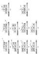
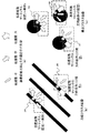
次に、本実施の形態の効果について説明する。図17は、第2の実施形態の効果を説明する図である。図17(a)は、(b)(c)で用いる誤差伝播方向とその量を示す矢印を説明するための図である。図17(a)に示すように、矢印の方向は、誤差伝播方向を示している。また、小の矢印は誤差伝播量が小さく、中の矢印は誤差伝播量が中で、大の矢印は誤差伝播量が大きいことを示す。
【0087】
図17(b)は、万線クラスタ画像の誤差伝播方向とその量を示している。また、アスタリスク*は、注目画素位置を示している。また、破線で囲まれた領域は誤差拡散マトリックスを示している。図17(b)のX5に示すように、モアレ現象の発生しやすいパターン画像領域のエッジ部分において、135°の輪郭方向に誤差を大きい割合で伝播させる誤差拡散マトリックスを選択して、入力画像をN値化すれば、その輪郭方向(135°の方向)に誤差を拡散させることが出来る。つまり、注目画素で発生した誤差を注目画素を含む注目クラスタの輪郭部分に拡散させる。これにより、注目クラスタの濃度情報を保存する傾向を高めることが出来、言い換えると局所領域の濃度情報の保存度合いを高めることが出来るため、よってモアレ現象を抑制できる。
【0088】
一方、X6に示すような所定の誤差拡散マトリックスは、エッジ部分以外に使用することにより、滑らかな中間調再現が可能となる。ここで、所定の誤差拡散マトリックスとは、図10(e)及び(j)に示すような誤差拡散マトリックス、すなわち、輪郭方向を考慮しない誤差拡散マトリックスのことである。
【0089】
図17(c)は、網点クラスタ画像の誤差伝播方向とその量を示している。図17(c)のX7、X8に示すように、モアレ現象の発生しやすいパターン画像領域のエッジ部分において、X7では、135°の輪郭方向、X8では45°の輪郭方向に誤差を大きい割合で伝播させる誤差拡散マトリックスを選択して、入力画像をN値化すれば、その輪郭方向(X7では135°の方向、X8では45°の方向)に誤差を拡散させることが出来る。つまり、注目画素で発生した誤差を注目画素を含む注目クラスタの輪郭部分に拡散させる。これにより、注目クラスタの濃度情報を保存する傾向を高めることが出来、言い換えると局所領域の濃度情報の保存度合いを高めることが出来るため、よってモアレ現象を抑制できる。
【0090】
一方、X9に示すような所定の誤差拡散マトリックスは、エッジ部分以外に使用することにより、滑らかな中間調再現が可能となる。なお、ここで、所定の誤差拡散マトリックスとは、図17(b)で説明したのと同様に、図10(e)及び(j)に示すような誤差拡散マトリックス、すなわち、輪郭方向を考慮しない誤差拡散マトリックスのことである。輪郭方向検出手段72により輪郭方向が不明又は輪郭が無いと判断された場合に、このような所定の誤差拡散マトリックスを使用する。
【0091】
なお、輪郭方向抽出手段72と、誤差拡散手段73については上記例に限るものではない。
【0092】
(第3の実施の形態)
次に、第3の実施の形態について説明する。第3の実施の形態の画像処理装置は、第1の実施の形態に係る画像処理装置と構成が同じであるため、図1を用いて説明する。図1に示すように、画像処理装置210は、画像入力手段11と、エッジ度抽出手段12と、誤差拡散手段121とを有する。
【0093】
画像入力手段11は、スキャンイン画像を入力する。エッジ度抽出手段12は、入力画像に対して所定領域のエッジ度を算出する。また、エッジ度抽出手段12は、入力画像の所定領域におけるエッジの分布度を抽出する。誤差拡散手段121は、エッジ度算出結果を参照して入力画像を誤差拡散法によりN値化を行う。なお、誤差拡散手段121でのN値化は2値化であってもよい。エッジ度抽出手段12については、第1の実施形態で説明したものと同様であるためここでは説明を省略する。
【0094】
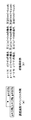
次に、誤差拡散手段13を図12、図13を用いて説明する。図12は、誤差拡散手段のブロック図である。また、図13は、伝播率を説明する図であり、(a)は誤差拡散マトリクスの例を示し、(b)は伝播率係数を示している。図12に示すように、誤差拡散手段121は、誤差拡散N値化部122と、誤差拡散伝播係数変更部123とを有する。
【0095】
誤差拡散伝播係数変更部123は、エッジ部抽出手段12からのエッジ度検出結果またはエッジ分布度検出結果E2(またはEw2またはEww2)を参照して、伝播係数を変更する。ここで、伝播係数とは、図13でpと示したような、誤差拡散マトリックス係数に乗算する伝播率を決定する係数のことである。誤差拡散伝播係数変更部123は、注目画素とは関係のない他領域からの誤差を低減させるために、図13(b)に示すように、
・エッジ方向検出結果E2(またはEw2またはEww2)がエッジ度強Eh(またはエッジ度強Ewhまたはエッジ分布度強Ewwh)である場合には、伝播係数p=1.00とし、
・エッジ方向検出結果E2(またはEw2またはEww2)がエッジ度中Em(またはエッジ度中Ewmまたはエッジ分布度中Ewwm)である場合には、伝播係数p=0.75とし、
・エッジ方向検出結果E2(またはEw2またはEww2)がエッジ度弱El(またはエッジ度弱Ewlまたはエッジ分布度低Ewwl)である場合には、伝播係数p=0.50とする。
【0096】
このように、抽出エッジ度が強いまたは抽出エッジ分布が高い場合には、伝播係数を1.00または1.00に近い数値に変更する。誤差拡散N値化部122は、選択された誤差拡散マトリックスを用いて、入力画像B1のN値化を行う。
【0097】
次に、図14を用いて、画像処理装置の別の例を説明する。図14は、画像処理装置の他の例を示すブロック図である。図14に示すように、画像処理装置310は、画像入力手段141と、エッジ度抽出手段142と、濃度抽出手段144と、誤差拡散手段143とを有する。上述した画像処理装置210と異なる点は、濃度抽出手段144を有する点である。したがって、画像入力手段141とエッジ度抽出手段142については上記と同様であるため、ここでは説明を省略する。
【0098】
濃度抽出手段144は、所定領域の濃度を抽出し、その抽出濃度が予め用意した設定範囲の濃度であるか否かを判定し、設定範囲内であればDon、設定範囲外であればDoffとし、この結果を誤差拡散手段143に出力する。誤差拡散手段143は、濃度抽出手段144からの入力を参照して誤差拡散処理をする。具体的には、誤差拡散手段143は、濃度抽出手段144からの入力が設定範囲内の濃度Donである場合には、エッジ度抽出手段142の結果に従い伝播係数を変更する。
【0099】
一方、誤差拡散手段143は、濃度抽出手段144からの入力が設定範囲外の濃度Doffであれば誤差拡散手段143は、エッジ度抽出手段142の結果によらず指定の伝播係数を使用するようにする。このような処理を行うことにより、注目画素とは関係ない他領域からの誤差を低減させることが出来る。つまり、注目している局所領域の濃度情報の保存度合いを高めることが出来るため、よってモアレ現象を抑制できる。
【0100】
次に、本実施の形態に係る画像処理について説明する。図15は、画像処理のフローチャートである。ステップ301において、画像入力手段11に画像が入力される。エッジ度抽出処理に入り、ステップ302において、エッジ度検出手段12は、入力画像B1に対して、所定領域のエッジ量を算出する。次に、ステップ303において、エッジ度抽出手段12は、算出されたエッジ量を閾値と比較参照し、そのエッジ度結果を誤差拡散手段121に出力する。
【0101】
次に、誤差拡散処理に入り、ステップ304において、誤差拡散伝播係数変更部123は、エッジ度結果を参照して、伝播係数を変更する。ステップ305において、誤差拡散N値化部122は、変更された伝播係数を用いてN値化を行う。ステップ306において、残りの画素が有るかどうか又は残りの画素領域が有るかどうかを判断し、残りの画素又は残りの画素領域がある場合には、ステップ302に進む。一方、残りの画素又は残りの画素領域が無い場合には、処理を終了する。
【0102】
次に、本実施の形態の効果について説明する。図18は、第3の実施形態の効果を説明する図である。図18(a)は、(b)(c)で用いる誤差伝播方向とその量を示す矢印を説明するための図である。図18(a)のように、矢印の方向は、誤差伝播方向を示している。また、小の矢印は、は誤差伝播量が小さく、中の矢印は誤差伝播量が中で、大の矢印は誤差伝播量が大きいことを示す。
【0103】
図18(b)は、伝播率の制御がない場合の網点クラスタ画像の誤差伝播方向とその量を示している。図18(c)は、伝播率の制御がある場合の網点クラスタ画像の誤差伝播方向とその量を示している。また、図18(b)において、アスタリスク*は、注目画素位置を示している。破線で囲まれた領域は固定(一般形)の誤差拡散マトリックスを示している。
【0104】
また、図18(b)に示すように、矢印Y1、Y2、Y3は全て同じ大きさ矢印で示されており、伝播量が変わらないことを表している。すなわち、伝播率の制御はないため、注目画素とは関係のない他の領域からの誤差を低減することはできない。図18(c)に示すように、矢印Y4、Y5、Y6は距離が遠くなるごとに矢印が小さくなっている。従って、誤差拡散伝播係数変更部123は、図13(b)に示すように、P=0.75、0.50のような伝播係数に変更して、距離遠くなるごとに伝播量が小さくなるようにしている。本実施の形態によれば、伝播率の制御があるため、注目画素とは関係ない他領域からの誤差を低減させることができる。つまり、注目している局所領域の濃度情報の保存度合いを高めることが出来るため、よってモアレ現象を抑制できる。
【0105】
なお、濃度抽出手段144、誤差拡散手段143については一例を示しており、上記例に限るものではない。
【0106】
上記各実施の形態によれば、誤差拡散法において画像の局所領域における濃度情報の保存を実現することができる。また、入力画像の幾何情報を利用して誤差の拡散を制御することにより、スキャン画像の特徴を考慮した精度の高い濃度情報の保存を実現することができる。更に、画像の他領域から伝播されてきた不要な誤差を制御し、局所領域の濃度情報を保存することができる。
【0107】
また、画像処理装置における各処理は、画像処理プログラムによって実行される。画像処理プログラムは、ハードウエアと協働し、ハードウエアと一体となって画像処理を行う。ハードウエアは、図示は省略するが、CPUと、ROMやRAM等の内部記憶装置と、FDD、HDD、CD−ROMドライバ等の外部記憶装置と、キーボードやマウス等の入力装置と、プリンタ等の出力装置と、表示装置とを有するコンピュータその他によって構成される。
【0108】
また、画像処理方法は、画像処理プログラムとして、FD、HD、CD−ROM等の記憶媒体に記憶されており、それぞれが対応する外部記憶装置に装着され、実行時に読み出されてRAMにロードされる。なお、画像処理プログラムが記憶される記憶媒体は、ROM等の半導体メモリでも良い。
【0109】
以上本発明の好ましい実施の形態について詳述したが、本発明は係る特定の実施形態に限定されるものではなく、特許請求の範囲に記載された本発明の要旨の範囲内において、種々の変形・変更が可能である。
【発明の効果】
以上説明した通り、本発明によれば、局所領域の濃度情報の保存度合いを高めることが出来るため、モアレ現象を抑制できる。
【図面の簡単な説明】
【図1】第1の実施の形態に係る画像処理装置を示すブロック図である。
【図2】図1のエッジ度抽出手段のブロック図である。
【図3】図2のエッジ度抽出手段を説明するための図である。
【図4】図1の誤差拡散手段を説明するための図である。
【図5】図4の誤差拡散マトリックス記憶部に格納される誤差拡散マトリックスの一例を示す図である。
【図6】第1の実施形態に係る画像処理のフローチャートである。
【図7】第2の実施形態に係る画像処理装置のブロック図である。
【図8】図7の輪郭方向抽出手段のブロック図である。
【図9】図7の誤差拡散手段のブロック図である。
【図10】図9の誤差拡散マトリックス記憶部に格納される誤差拡散マトリックスの一例を示す図である。
【図11】第2の実施形態に係る画像処理のフローチャートである。
【図12】第3の実施形態に係る誤差拡散手段のブロック図である。
【図13】伝播率を説明する図である。
【図14】第3の実施形態に係る画像処理装置のブロック図である。
【図15】第3の実施形態に係る画像処理のフローチャートである。
【図16】第1の実施形態の効果を説明する図である。
【図17】第2の実施形態の効果を説明する図である。
【図18】第3の実施形態の効果を説明する図である。
【符号の説明】
10、110、210、310 画像処理装置
11、71、141 画像入力手段
12、142 エッジ度検出手段
13、73、121、143 誤差拡散手段
22、23、24、25 エッジ検出部
26、86 判定部
42、92、122 誤差拡散N値化部
43、93 誤差拡散マトリックス選択部
44、94 誤差拡散マトリックス記憶部
72 輪郭方向抽出手段
82、83、84、85 輪郭検出部
123 誤差拡散伝播係数変更部
144 濃度抽出手段[0001]
TECHNICAL FIELD OF THE INVENTION
The present invention relates to an image processing apparatus, an image processing method, and an image processing program, and more particularly, to a technique of N-value processing using an error diffusion method.
[0002]
[Prior art]
2. Description of the Related Art Conventionally, a moiré phenomenon often appears in an image input by a scanner or the like, and a moiré phenomenon appears when halftone processing is performed on the scanned image. In the first place, the moiré phenomenon means that when information captured by a scanner or the like is replaced with a digital signal, information is lost in the resolution direction and gradation direction, so the frequency and sampling frequency of the original image and the halftone processing Frequency and the like cause interference, causing a moire phenomenon.
[0003]
When the scan image (M value) is subjected to simple N-value conversion (N <M), the occurrence of the moiré phenomenon becomes conspicuous, but the density information corresponding to the gradation direction is lost due to the simple N-value conversion. It is because it has been done. There is an error diffusion method as a method of reproducing halftones for a scanned image (M value). When the error diffusion method is used for the N-value conversion, the moire phenomenon can be relatively suppressed. The reason is that the density information of the entire image is stored by the error diffusion method. However, although the use of the error diffusion method may have the effect of suppressing the moiré phenomenon, the moiré phenomenon cannot be generally prevented.
[0004]
Therefore, some error diffusion methods described in Patent Literature 1 aim to reduce the moire phenomenon by adding noise to scanned image data. According to the error diffusion method described in Patent Document 1, an edge detector detects an edge of input image data, and a noise level determining unit adds noise to the image data according to a result of the edge detection. When generating additional image data and performing error diffusion in the error diffusion processing block, error diffusion is changed according to the noise-added image data to generate error diffusion data, and an output image is generated from the generated error diffusion data. Is generated to prevent moiré.
[0005]
Further, as another conventional technique, a binarization processing method described in Patent Document 2 has been proposed. According to the binarization processing method described in Patent Literature 2, the image is binarized by sequentially reading density data of each continuous pixel constituting the image and applying an error diffusion method to the read density data. In a binarization processing method for obtaining image data, by changing the content of an error diffusion matrix used for performing error diffusion processing on read image data according to a pixel of interest, the granularity near the edge of the image is obtained. This is to suppress noise.
[0006]
[Patent Document 1]
JP 2001-136388 A
[Patent Document 2]
JP-A-5-300373
[Problems to be solved by the invention]
However, the error diffusion method described in Patent Literature 1 has a problem that, by adding error noise, graininess in image quality is significantly reduced, isolated noise also appears, and a texture different from the input image is reproduced. .
[0007]
Further, the processing contents of the binarization processing method described in Patent Document 2 are described as follows. When image data changes from a white level to a black level, particularly, immediately before the image data changes from a white level to a black level, the contents of an error propagation matrix in the error diffusion method are changed. This is changed so that an extra dot is not printed on the edge portion. Therefore, the purpose is not related to the suppression of the moiré phenomenon, and the processing content cannot be expected to be effective in suppressing the moiré phenomenon.
[0008]
Further, in the case where the scan image (M value) is converted into N-values using the error diffusion method, the density information of the entire image is stored, but there is a problem that a moire phenomenon occurs.
[0009]
Therefore, an object of the present invention is to provide an image processing apparatus, an image processing method, and an image processing program that can suppress the moiré phenomenon, maintain sharpness, and suppress isolated points, in order to solve the above problem. .
[0010]
[Means for Solving the Problems]
In order to solve the above-mentioned problem, an image processing apparatus according to claim 1, wherein an image input means for inputting an image, and an edge degree extraction means for extracting an edge degree of a predetermined area of the input image input by the image input means Error diffusion means for changing an error diffusion matrix with reference to the edge degree extracted by the edge degree extraction means, and converting the input image into N-values based on the changed error diffusion matrix. Features.
[0011]
According to the first aspect of the present invention, the error diffusion matrix is changed with reference to the edge degree extracted by the edge degree extracting means, and the input image is converted into an N-value based on the changed error diffusion matrix. Therefore, it is possible to increase the tendency of preserving the density information in the periodic pattern image region, for example, the edge portion of the pattern image region where the moiré phenomenon is likely to occur, and it is possible to suppress the moiré phenomenon. In addition, it is possible to maintain granularity, maintain sharpness, and suppress isolated points.
[0012]
According to a second aspect of the present invention, in the image processing apparatus according to the first aspect, when the edge degree extracted by the edge degree extracting unit is large, the error diffusion unit changes the error diffusion matrix to a small size. It is characterized by doing. According to the second aspect of the present invention, since the error diffusion matrix size is reduced, error diffusion can be diffused closer to the edge portion. Thereby, the moiré phenomenon can be suppressed.
[0013]
According to a third aspect of the present invention, in the image processing apparatus according to the first or second aspect, when the edge degree extracted by the edge degree extraction unit is large, the error diffusion unit may determine a distance from the pixel of interest. It is characterized by changing to an error diffusion matrix in which a large coefficient is arranged in peripheral pixels having a short length. According to the third aspect of the present invention, the error diffusion matrix is changed to an error diffusion matrix in which a large coefficient is arranged in a peripheral pixel that is short from a target pixel and a short distance from a peripheral pixel. It can be more diffused to the periphery. Thereby, the moiré phenomenon can be suppressed.
[0014]
According to a fourth aspect of the present invention, in the image processing apparatus according to any one of the first to third aspects, the edge degree extracting unit extracts an edge distribution degree in a predetermined area of the input image. It is characterized by. According to the fourth aspect of the present invention, the distribution of edges in a predetermined area of the input image is extracted to change the error diffusion matrix.
[0015]
According to a fifth aspect of the present invention, there is provided an image processing apparatus comprising: image input means for inputting an image; contour direction extracting means for extracting a contour direction of a predetermined area of the input image input by the image input means; Error diffusion means for changing the error diffusion matrix with reference to the contour direction extracted by the means, and converting the input image into N-values based on the changed error diffusion matrix.
[0016]
According to the fifth aspect of the present invention, the error diffusion matrix is changed with reference to the contour direction extracted by the contour direction extracting means, and the input image is converted into N-values based on the changed error diffusion matrix. Therefore, the error can be diffused in the contour direction at the edge portion of the pattern image region where the moiré phenomenon is likely to occur. That is, the error generated at the target pixel is diffused to the contour of the target cluster including the target pixel. As a result, the tendency of storing the density information of the cluster of interest can be increased, in other words, the degree of storage of the density information of the local region can be increased, so that the moire phenomenon can be suppressed. In addition, it is possible to maintain granularity, maintain sharpness, and suppress isolated points. Here, a cluster is a block that forms a pattern, and represents a dot in a halftone pattern and a line in a line pattern.
[0017]
According to a sixth aspect of the present invention, in the image processing apparatus according to the fifth aspect, the error diffusion unit changes to an error diffusion matrix that diffuses an error at a high rate in the contour direction extracted by the contour direction extraction unit. It is characterized by doing. According to the sixth aspect of the invention, since the error diffusion matrix is changed to an error diffusion matrix that diffuses an error at a high rate in the contour direction extracted by the contour direction extracting means, the edge of the pattern image area where the moire phenomenon is likely to occur. In a portion, an error can be diffused in the contour direction. Thereby, the moiré phenomenon can be suppressed.
[0018]
According to a seventh aspect of the present invention, in the image processing apparatus according to the fifth aspect, the outline direction extracting unit extracts a plurality of outline direction candidates, and the error diffusion unit extracts the outline direction by the outline direction extracting unit. The error diffusion matrix is changed with reference to the plurality of contour direction candidates. According to the seventh aspect of the present invention, the error diffusion unit refers to the plurality of contour direction candidates extracted by the contour direction extraction unit, changes the error diffusion matrix, and generates a moiré phenomenon in the pattern image area. At the edge portion, the error is diffused in the contour direction. Thereby, the moiré phenomenon can be suppressed.
[0019]
According to an eighth aspect of the present invention, in the image processing apparatus according to any one of the fifth to seventh aspects, the error diffusion unit changes the error diffusion matrix with reference to a processing order direction. Features. According to the eighth aspect of the present invention, the error diffusion means changes the error diffusion matrix with reference to the processing order direction, and in the edge portion of the pattern image region where the moiré phenomenon is likely to occur, the error diffusion is performed in the contour direction. Is spread. Thereby, the moiré phenomenon can be suppressed.
[0020]
According to a ninth aspect of the present invention, in the image processing apparatus according to any one of the fifth to eighth aspects, the error diffusion unit determines that the outline direction is unknown or has no outline by the outline direction extraction unit. When it is determined, a predetermined error diffusion matrix is used. According to the ninth aspect of the present invention, the error diffusion means uses a predetermined error diffusion matrix when the contour direction extracting means determines that the contour direction is unknown or has no contour. By using a predetermined error diffusion matrix other than the part, smooth halftone reproduction can be performed.
[0021]
The image processing apparatus according to claim 10, wherein the image input means inputs an image, the edge degree extraction means extracts an edge degree of a predetermined area of the input image input by the image input means, and the edge degree extraction Error diffusion means for changing the propagation coefficient to be multiplied by the coefficient of the error diffusion matrix with reference to the edge degree extracted by the means, and converting the input image into an N-value using the changed propagation coefficient; It is characterized by having.
[0022]
According to the tenth aspect, the transmissivity coefficient by which the coefficient of the error diffusion matrix is multiplied is changed with reference to the edge degree extracted by the edge degree extracting means, and the input image is changed using the changed propagation coefficient. Is N-valued, it is possible to prevent an error generated in another region or another cluster in the input image from being propagated, and added to the cluster of interest or the pixel of interest as an unnecessary error and processed. . In other words, the degree of preservation of the density information of the local area of interest can be increased, so that the moire phenomenon can be suppressed. In addition, it is possible to maintain granularity, maintain sharpness, and suppress isolated points.
[0023]
Further, as described in
[0024]
The image processing device according to
[0025]
According to a thirteenth aspect of the present invention, in the image processing apparatus according to any one of the first to twelfth aspects, the N-value conversion is binarization.
[0026]
The image processing method according to claim 14, wherein an image input step of inputting an image, an edge degree extracting step of extracting an edge degree of a predetermined area of the input image input by the image input step, and an edge degree extracting step And an error diffusion step of changing the error diffusion matrix with reference to the edge degree extracted in the step, and converting the input image into an N-value based on the changed error diffusion matrix.
[0027]
According to the fourteenth aspect, the error diffusion matrix is changed with reference to the edge degree extracted in the edge degree extraction step, and the input image is converted into an N-value based on the changed error diffusion matrix. Therefore, it is possible to increase the tendency of preserving the density information in the periodic pattern image region, for example, the edge portion of the pattern image region where the moiré phenomenon is likely to occur, and it is possible to suppress the moiré phenomenon. In addition, it is possible to maintain granularity, maintain sharpness, and suppress isolated points.
[0028]
According to a fifteenth aspect of the present invention, in the image processing method of the fourteenth aspect, when the edge degree extracted in the edge degree extracting step is large, the error diffusion step is changed to an error diffusion matrix having a small size. It is characterized by doing. According to the fifteenth aspect, since the error diffusion matrix size is reduced, the error diffusion can be diffused closer to the edge portion. Thereby, the moiré phenomenon can be suppressed.
[0029]
According to a sixteenth aspect of the present invention, in the image processing method according to the fourteenth or fifteenth aspect, when the edge degree extracted in the edge degree extraction step is large, a distance from a target pixel is determined. It is characterized by changing to an error diffusion matrix in which a large coefficient is arranged in peripheral pixels having a short length. According to the sixteenth aspect of the invention, the error diffusion matrix is changed to an error diffusion matrix in which a large coefficient is arranged in a peripheral pixel short in distance from a target pixel and a short distance from a peripheral pixel in a short distance from the target pixel. It can be more diffused to the periphery. Thereby, the moiré phenomenon can be suppressed.
[0030]
An image processing method according to claim 17, wherein an image input step of inputting an image, a contour direction extracting step of extracting a contour direction of a predetermined area of the input image input in the image input step, and the contour direction extracting step An error diffusion step of changing the error diffusion matrix with reference to the contour direction extracted in the step, and converting the input image into an N-value based on the changed error diffusion matrix.
[0031]
According to the seventeenth aspect, the error diffusion matrix is changed with reference to the contour direction extracted in the contour direction extracting step, and the input image is converted into an N-value based on the changed error diffusion matrix. Therefore, the error can be diffused in the contour direction at the edge portion of the pattern image region where the moiré phenomenon is likely to occur. That is, the error generated at the target pixel is diffused to the contour of the target cluster including the target pixel. As a result, the tendency of storing the density information of the cluster of interest can be increased, in other words, the degree of storage of the density information of the local region can be increased, so that the moire phenomenon can be suppressed. In addition, it is possible to maintain granularity, maintain sharpness, and suppress isolated points.
[0032]
An image processing method according to claim 18, wherein an image input step of inputting an image, an edge degree extracting step of extracting an edge degree of a predetermined area of the input image input in the image input step, and an edge degree extracting step An error diffusion step of changing a propagation coefficient to be multiplied by a coefficient of an error diffusion matrix with reference to the edge degree extracted by the step, and converting the input image into an N-value using the changed propagation coefficient; It is characterized by having.
[0033]
According to the eighteenth aspect of the present invention, by referring to the edge degree extracted in the edge degree extraction step, the transmissivity coefficient by which the coefficient of the error diffusion matrix is multiplied is changed, and the input image is changed using the changed propagation coefficient. Is N-valued, it is possible to prevent an error generated in another region or another cluster in the input image from being propagated, and added to the cluster of interest or the pixel of interest as an unnecessary error and processed. . In other words, the degree of preservation of the density information of the local area of interest can be increased, so that the moire phenomenon can be suppressed. In addition, it is possible to maintain granularity, maintain sharpness, and suppress isolated points.
[0034]
20. An image processing program according to claim 19, further comprising: a computer for processing an input image input from the image input means, the edge degree extracting means for extracting an edge degree of a predetermined area of the input image; The error diffusion matrix is changed with reference to the edge degree extracted by the means, and based on the changed error diffusion matrix, the input image is caused to function as an error diffusion means for converting the input image into N values.
[0035]
According to the nineteenth aspect, the error diffusion matrix is changed with reference to the edge degree extracted by the edge degree extracting means, and the input image is converted into an N-value based on the changed error diffusion matrix. Therefore, it is possible to increase the tendency of preserving the density information in the periodic pattern image region, for example, the edge portion of the pattern image region where the moiré phenomenon is likely to occur, and it is possible to suppress the moiré phenomenon. In addition, it is possible to maintain granularity, maintain sharpness, and suppress isolated points.
[0036]
According to a twentieth aspect of the image processing program of the nineteenth aspect, the error diffusion means changes the error diffusion matrix to a smaller size when the edge degree extracted by the edge degree extraction means is large. It is characterized by doing. According to the twentieth aspect, since the size of the error diffusion matrix is reduced, the error diffusion can be diffused closer to the edge portion. Thereby, the moiré phenomenon can be suppressed.
[0037]
According to a twenty-first aspect, in the image processing program according to the twelfth or twelfth aspect, the error diffusion unit is configured to determine a distance from the target pixel when the edge degree extracted by the edge degree extraction unit is large. It is characterized by changing to an error diffusion matrix in which a large coefficient is arranged in peripheral pixels having a short length. According to the twenty-first aspect of the present invention, the error diffusion matrix is changed to an error diffusion matrix in which a large coefficient is arranged in a peripheral pixel that is short from a target pixel and a short distance from a peripheral pixel. It can be more diffused to the periphery. Thereby, the moiré phenomenon can be suppressed.
[0038]
An image processing program according to
[0039]
According to the invention of
[0040]
24. An image processing program according to
[0041]
According to the twenty-third aspect, with reference to the edge degree extracted by the edge degree extraction unit, the transmissivity coefficient by which the coefficient of the error diffusion matrix is multiplied is changed, and the input image is input using the changed propagation coefficient. Is N-valued, it is possible to prevent an error generated in another region or another cluster in the input image from being propagated, and added to the cluster of interest or the pixel of interest as an unnecessary error and processed. . In other words, the degree of preservation of the density information of the local area of interest can be increased, so that the moire phenomenon can be suppressed. In addition, it is possible to maintain granularity, maintain sharpness, and suppress isolated points.
[0042]
BEST MODE FOR CARRYING OUT THE INVENTION
(First Embodiment)
FIG. 1 is a diagram for explaining the image processing apparatus according to the first embodiment.
As shown in FIG. 1, the image processing apparatus 10 includes an
[0043]
The
[0044]
The
[0045]
Next, the edge degree extracting means 12 will be described. FIG. 2 is a block diagram of the edge degree extracting means. As shown in FIG. 2, the edge
[0046]
The 0 ° direction
[0047]
The
[0048]
In the determination of the edge strength in the
If M2> T0, the degree of edge = strong Eh;
If T0 ≧ M2> T1, then set the degree of edge = medium Em,
If T1 ≧ M2, the edge degree is set to weak El, and any of Eh, Em, and El is set to the output value E2.
[0049]
Note that M2 may be the sum of the output values A2, B2, C2, and D2 of the edge
[0050]
Next, the processing of the edge degree extracting means will be described. FIG. 3 is a diagram for explaining the edge degree extracting means. FIG. 3A shows an example of an input image B <b> 1 to the edge
[0051]
The
If W2> T10, the edge degree = strong Ewh;
If T10 ≧ W2> T11, the edge degree = medium Ewm,
If T11 ≧ W2, the edge degree = weak Ewl,
One of Ewh, Ewm, and Ewl is set as the output value Ew2.
[0052]
FIG. 3D shows an example of a reference range when judging the degree of distribution of edges. The area inside each broken line indicates the reference range. In FIG. 3D, an asterisk * indicates a target pixel. The edge strength Ew2 is obtained for each of the regions α, β, γ, and δ as described above, and the obtained values are set to Ew2α, Ew2β, Ew2γ, and Ew2δ, respectively.
[0053]
Next, the edge intensity Ew2α is compared with the threshold T20 and the threshold T21 (T20> T21),
If Ew2α> T20, the edge degree = strong Ew2αH,
・ If T20 ≧ Ew2α> T21, the edge degree = medium Ew2αm,
If T21 ≧ Ew2α, the edge degree is set to be weak Ew2αl, and one of Ew2αh, Ew2αm, and Ew2αl is set as the calculated value Eww2α.
[0054]
Ew2β, Ew2γ, and Ew2δ are also calculated in the same manner as Ew2α, and the calculated values are Eww2β, Eww2γ, and Eww2δ. Then, Eww2α, Eww2β, Eww2γ, and Eww2δ are compared with the threshold T30, the threshold T31 (T30> T31), and the threshold T32, respectively.
When the threshold T32 or more among Eww2α, Eww2β, Eww2γ, and Eww2δ is equal to or larger than the threshold T30, the edge distribution degree is set to high Ewwh,
-If the threshold T32 or more among Eww2α, Eww2β, Eww2γ, and Eww2δ is equal to or more than the threshold T31, the edge distribution degree is set to medium Ewwm.
In other cases, the edge distribution degree is set to low Ewl, and one of Ewwh, Ewwm, and Ewwl is set as the output value Eww2 of the edge distribution degree. The output value Eww2 of the edge distribution degree is input to an error diffusion
[0055]
Next, the error diffusion means 13 will be described with reference to FIGS. FIG. 4 is a diagram for explaining the error diffusion means of FIG. As shown in FIG. 4, the error diffusion means 13 includes an error diffusion N-
[0056]
5A shows an error diffusion matrix having the smallest size, FIG. 5B shows an error diffusion matrix having the next smallest size after FIG. 5A, and FIGS. 5C to 5F show error diffusion matrices having the same size. Is shown. FIGS. 5D and 5E show error diffusion matrices in which larger coefficients are arranged in peripheral pixels whose distance from the target is short.
The error diffusion
When the output value E2 (or Ew2 or Eww2) from the
When the output value E2 (or Ew2 or Eww2) from the
When the output value E2 (or Ew2 or Eww2) from the
[0057]
As described above, when the extracted edge degree is high or the extracted edge distribution is high (when the edge degree is large), the error diffusion
[0058]
Next, an operation of image processing according to the present embodiment will be described. FIG. 6 shows a flowchart of the image processing. In step 101, an image is input to the
[0059]
Next, error diffusion processing is started. In step 104, the error diffusion
[0060]
Next, the effects of the present embodiment will be described with reference to FIG. FIG. 16 is a diagram illustrating the effect of the first embodiment. FIG. 16A is a diagram for explaining a target pixel position and an error diffusion matrix used in FIGS. 16B and 16C. An asterisk * indicates a pixel position of interest. A region surrounded by a broken line indicates an error diffusion matrix.
[0061]
FIG. 16B shows an example of a parallel line cluster image. As shown by X1 in FIG. 16B, in the edge portion of the pattern image region where the moiré phenomenon is likely to occur, the error can be diffused closer to the edge portion by reducing the error diffusion matrix size. . That is, the degree of preservation of the density information of the local region of the edge portion can be increased, and therefore, the moiré phenomenon can be suppressed. Further, by using an error diffusion matrix having a conventional size (large error diffusion matrix size) as indicated by X2 in FIG. 16B except for an edge portion, smooth halftone reproduction can be realized.
[0062]
FIG. 16C shows an example of a halftone dot cluster image. As shown by X3 in FIG. 16C, in the edge portion of the pattern image area where the moiré phenomenon is likely to occur, the error can be diffused closer to the edge portion by reducing the error diffusion matrix size. . That is, the degree of preservation of the density information of the local region of the edge portion can be increased, and therefore, the moiré phenomenon can be suppressed. A conventional half-size error diffusion matrix (large error diffusion matrix size) as indicated by X4 in FIG. 16C can be used to reproduce smooth halftones by using other than the edge portion.
[0063]
In the present embodiment, the
[0064]
(Second embodiment)
Next, an image processing apparatus according to a second embodiment will be described. FIG. 7 is a block diagram of the image processing apparatus according to the second embodiment. As shown in FIG. 7, the image processing apparatus 110 has an
[0065]
The
[0066]
The
[0067]
Next, the contour direction extracting means 72 will be described with reference to FIG. FIG. 8A is a block diagram of the contour direction extracting means. FIG. 8B shows an error diffusion processing direction, which will be described later in detail.
[0068]
As shown in FIG. 8A, the contour direction extracting means 72 includes a 0 ° direction
[0069]
Each of the contour
[0070]
In the determination of the contour direction by the
[0071]
That is,
If M8 ≦ T40, the
If M8> T40 and M8 = A8, the contour direction result E8 = D0,
If M8> T40 and M8 = B8, set the contour direction result E8 = D45;
If M8> T40 and M8 = C8, the contour direction result E8 = D90,
If M8> T40 and M8 = D8, the contour direction result E8 = D135.
[0072]
Next, the error diffusion means will be described. FIG. 9 is a block diagram showing an example of the error diffusion means of FIG. As shown in FIG. 9, the
[0073]
FIGS. 10A to 10E are diagrams illustrating examples of the error diffusion matrix stored in the error diffusion
If the contour direction detection result E8 = Dnon, the error diffusion
If the contour direction detection result E8 = D0, the error diffusion matrix shown in FIG.
If the contour direction detection result E8 = D45, the error diffusion matrix shown in FIG.
If the contour direction detection result E8 = D90, the error diffusion matrix shown in FIG.
If the contour direction detection result E8 = D135, the error diffusion matrix of FIG. 10D is selected.
[0074]
As described above, the error diffusion
[0075]
Next, another example of the contour
[0076]
The 0 ° direction
[0077]
The
[0078]
FIG. 8B shows the error diffusion processing direction. FIG. 8B shows an example in which the line processing direction differs depending on the line. As shown in FIG. 8B, a case where the input image is processed from left to right is defined as an R direction, and a case where the input image is processed from right to left is defined as an L direction. Specific determination is shown below. First, when the error diffusion processing direction is the R direction,
The
The
If Mf8> T40 and Mf8 = B8, the contour direction result Ew8 = Dr45;
If Mf8> T40 and Mf8 = C8, the contour direction result Ew8 = Dr90;
If Mf8> T40 and Mf8 = D8, the contour direction result Ew8 = Dr135.
[0079]
However,
-If Mf8> T40, Mf8 = A8, Ms8 = B8, and Ms8 * e≥Mf8, the
If Mf8> T40, Mf8 = B8, Ms8 = C8, and Ms8 × e ≧ Mf8, the contour direction detection result Ew8 = Dr90;
If Mf8> T40, Mf8 = C8, Ms8 = D8, and Ms8 × e ≧ Mf8, the contour direction detection result Ew8 = Dr135.
[0080]
When there are a plurality of error diffusion processing directions and there are R and L directions, the same applies to the above when the error diffusion processing direction is the R direction.
When the error diffusion processing direction is the L direction,
The
-If Mf8> T40 and Mf8 = A8, the
If Mf8> T40 and Mf8 = B8, the contour direction result Ew8 = D145,
If Mf8> T40 and Mf8 = C8, the contour direction result Ew8 = D190,
If Mf8> T40 and Mf8 = D8, the contour direction result Ew8 = Dl135.
[0081]
However,
-If Mf8> T40, Mf8 = A8, Ms8 = D8, and Ms8 * e≥Mf8, the
If Mf8> T40, Mf8 = D8, Ms8 = C8, and Ms8 × e ≧ Mf8, the contour direction result Ew8 = D190,
If Mf8> T40, Mf8 = C8, Ms8 = B8, and Ms8 × e ≧ Mf8, the contour direction result Ew8 = D145. Here, e is one or more real numbers.
[0082]
Next, another example of the
If the contour direction detection result Ew8 = Drnon, the error diffusion
If the contour direction detection result Ew8 = Dr0, the error diffusion matrix shown in FIG.
If the contour direction detection result Ew8 = Dr45, the error diffusion matrix of FIG.
If the contour direction detection result Ew8 = Dr90, the error diffusion matrix of FIG.
If the contour direction detection result Ew8 = Dr135, the error diffusion matrix of FIG.
If the contour direction detection result Ew8 = Dlnon, the error diffusion matrix of FIG.
If the contour direction detection result Ew8 = D10, the error diffusion matrix of FIG.
If the contour direction detection result Ew8 = D145, the error diffusion matrix of FIG.
If the contour direction detection result Ew8 = D190, the error diffusion matrix of FIG.
If the contour direction detection result Ew8 = Dl135, the error diffusion matrix of FIG. 10I is selected.
[0083]
As described above, the
[0084]
Next, image processing according to the present embodiment will be described. FIG. 11 is a flowchart illustrating an embodiment of the image processing. In
[0085]
Next, an error diffusion process is started. In
[0086]
Next, effects of the present embodiment will be described. FIG. 17 is a diagram illustrating the effect of the second embodiment. FIG. 17A is a diagram for explaining the arrows indicating the error propagation directions and their amounts used in (b) and (c). As shown in FIG. 17A, the direction of the arrow indicates the error propagation direction. The small arrow indicates that the error propagation amount is small, the middle arrow indicates that the error propagation amount is medium, and the large arrow indicates that the error propagation amount is large.
[0087]
FIG. 17B shows the error propagation direction and the amount of the line cluster image. An asterisk * indicates the position of the pixel of interest. A region surrounded by a broken line indicates an error diffusion matrix. As indicated by X5 in FIG. 17B, an error diffusion matrix that propagates an error at a large rate in the 135 ° contour direction is selected at the edge portion of the pattern image area where the moiré phenomenon is likely to occur, and the input image is converted. If the value is converted to an N value, an error can be diffused in the contour direction (135 ° direction). That is, the error generated at the target pixel is diffused to the contour of the target cluster including the target pixel. As a result, the tendency of storing the density information of the cluster of interest can be increased, in other words, the degree of storage of the density information of the local region can be increased, so that the moire phenomenon can be suppressed.
[0088]
On the other hand, when a predetermined error diffusion matrix such as X6 is used for other than the edge portion, a smooth halftone can be reproduced. Here, the predetermined error diffusion matrix is an error diffusion matrix as shown in FIGS. 10E and 10J, that is, an error diffusion matrix that does not consider the contour direction.
[0089]
FIG. 17C shows the error propagation direction and the amount of the halftone dot cluster image. As shown by X7 and X8 in FIG. 17C, in the edge portion of the pattern image region where the moiré phenomenon is likely to occur, the error is large at a contour direction of 135 ° for X7 and 45 ° for X8. If an error diffusion matrix to be propagated is selected and the input image is converted into N-values, the error can be diffused in the contour direction (135 ° direction in X7, 45 ° direction in X8). That is, the error generated at the target pixel is diffused to the contour of the target cluster including the target pixel. As a result, the tendency of storing the density information of the cluster of interest can be increased, in other words, the degree of storage of the density information of the local region can be increased, so that the moire phenomenon can be suppressed.
[0090]
On the other hand, when a predetermined error diffusion matrix such as X9 is used for other than an edge portion, smooth halftone reproduction can be performed. Here, the predetermined error diffusion matrix is an error diffusion matrix as shown in FIGS. 10E and 10J, that is, the contour direction is not considered, as described with reference to FIG. 17B. Error diffusion matrix. When the contour direction detecting means 72 determines that the contour direction is unknown or has no contour, such a predetermined error diffusion matrix is used.
[0091]
The contour direction extracting means 72 and the error diffusion means 73 are not limited to the above example.
[0092]
(Third embodiment)
Next, a third embodiment will be described. The image processing apparatus according to the third embodiment has the same configuration as the image processing apparatus according to the first embodiment, and thus will be described with reference to FIG. As shown in FIG. 1, the image processing device 210 includes an
[0093]
The
[0094]
Next, the error diffusion means 13 will be described with reference to FIGS. FIG. 12 is a block diagram of the error diffusion means. FIGS. 13A and 13B are diagrams for explaining the transmissivity. FIG. 13A shows an example of an error diffusion matrix, and FIG. 13B shows a transmissivity coefficient. As shown in FIG. 12, the
[0095]
The error diffusion propagation
When the edge direction detection result E2 (or Ew2 or Eww2) is the strong edge degree Eh (or the strong edge degree Ewh or the strong edge distribution degree Ewwh), the propagation coefficient p is set to p = 1.00;
When the edge direction detection result E2 (or Ew2 or Eww2) is the middle of the edge degree Em (or the middle of the edge degree Ewm or the middle of the edge distribution Ewwm), the propagation coefficient p is set to 0.75;
When the edge direction detection result E2 (or Ew2 or Eww2) is weak edge degree El (or weak edge degree Ewl or low edge distribution degree Ewl), the propagation coefficient p is set to p = 0.50.
[0096]
As described above, when the extraction edge degree is high or the extraction edge distribution is high, the propagation coefficient is changed to 1.00 or a numerical value close to 1.00. The error diffusion N-
[0097]
Next, another example of the image processing apparatus will be described with reference to FIG. FIG. 14 is a block diagram illustrating another example of the image processing apparatus. As shown in FIG. 14, the
[0098]
The density extraction means 144 extracts the density of a predetermined area, determines whether or not the extracted density is within a preset set range, and sets it to Don if it is within the set range and Doff if it is outside the set range. The result is output to the error diffusion means 143. The
[0099]
On the other hand, if the input from the density extracting means 144 is the density Doff outside the set range, the error diffusing means 143 uses the designated propagation coefficient regardless of the result of the edge
[0100]
Next, image processing according to the present embodiment will be described. FIG. 15 is a flowchart of the image processing. In
[0101]
Next, error diffusion processing is started, and in step 304, the error diffusion propagation
[0102]
Next, effects of the present embodiment will be described. FIG. 18 is a diagram illustrating the effect of the third embodiment. FIG. 18A is a view for explaining arrows indicating the error propagation direction and the amount used in FIGS. 18B and 18C. As shown in FIG. 18A, the direction of the arrow indicates the error propagation direction. The small arrow indicates that the error propagation amount is small, the middle arrow indicates that the error propagation amount is medium, and the large arrow indicates that the error propagation amount is large.
[0103]
FIG. 18B shows the error propagation direction and the amount of the halftone dot cluster image when the propagation rate is not controlled. FIG. 18C illustrates the error propagation direction and the amount of the halftone dot cluster image when the propagation rate is controlled. In FIG. 18B, an asterisk * indicates the position of the pixel of interest. A region surrounded by a broken line indicates a fixed (general type) error diffusion matrix.
[0104]
As shown in FIG. 18B, arrows Y1, Y2, and Y3 are all indicated by arrows of the same size, indicating that the propagation amount does not change. That is, since there is no control of the propagation rate, it is not possible to reduce an error from another region unrelated to the pixel of interest. As shown in FIG. 18C, the arrows Y4, Y5, and Y6 become smaller as the distance increases. Therefore, the error diffusion propagation
[0105]
Note that the
[0106]
According to each of the above embodiments, it is possible to realize storage of density information in a local region of an image in the error diffusion method. Further, by controlling the diffusion of the error using the geometric information of the input image, it is possible to realize high-precision storage of density information in consideration of the characteristics of the scanned image. Further, unnecessary errors transmitted from other regions of the image can be controlled, and the density information of the local region can be stored.
[0107]
Each process in the image processing apparatus is executed by an image processing program. The image processing program cooperates with hardware and performs image processing integrally with the hardware. Although not shown, the hardware includes a CPU, an internal storage device such as a ROM and a RAM, an external storage device such as an FDD, an HDD, a CD-ROM driver, an input device such as a keyboard and a mouse, and a printer and the like. It is constituted by a computer or the like having an output device and a display device.
[0108]
The image processing method is stored as an image processing program in a storage medium such as an FD, an HD, or a CD-ROM. Each of the image processing methods is mounted on a corresponding external storage device, read out at the time of execution, and loaded into the RAM. You. The storage medium storing the image processing program may be a semiconductor memory such as a ROM.
[0109]
Although the preferred embodiments of the present invention have been described in detail, the present invention is not limited to the specific embodiments, and various modifications may be made within the scope of the present invention described in the appended claims.・ Change is possible.
【The invention's effect】
As described above, according to the present invention, the degree of preservation of the density information of the local region can be increased, so that the moire phenomenon can be suppressed.
[Brief description of the drawings]
FIG. 1 is a block diagram illustrating an image processing apparatus according to a first embodiment.
FIG. 2 is a block diagram of an edge degree extraction unit of FIG. 1;
FIG. 3 is a diagram for explaining an edge degree extraction unit in FIG. 2;
FIG. 4 is a diagram for explaining an error diffusion unit in FIG. 1;
FIG. 5 is a diagram showing an example of an error diffusion matrix stored in an error diffusion matrix storage unit of FIG.
FIG. 6 is a flowchart of image processing according to the first embodiment.
FIG. 7 is a block diagram of an image processing apparatus according to a second embodiment.
FIG. 8 is a block diagram of a contour direction extracting unit of FIG. 7;
FIG. 9 is a block diagram of the error diffusion means of FIG. 7;
FIG. 10 is a diagram illustrating an example of an error diffusion matrix stored in an error diffusion matrix storage unit of FIG. 9;
FIG. 11 is a flowchart of image processing according to the second embodiment.
FIG. 12 is a block diagram of an error diffusion unit according to a third embodiment.
FIG. 13 is a diagram illustrating a propagation rate.
FIG. 14 is a block diagram of an image processing apparatus according to a third embodiment.
FIG. 15 is a flowchart of image processing according to the third embodiment.
FIG. 16 is a diagram illustrating the effect of the first embodiment.
FIG. 17 is a diagram illustrating the effect of the second embodiment.
FIG. 18 is a diagram illustrating an effect of the third embodiment.
[Explanation of symbols]
10, 110, 210, 310 Image processing device
11, 71, 141 Image input means
12, 142 Edge degree detecting means
13, 73, 121, 143 Error diffusion means
22, 23, 24, 25 Edge detector
26, 86 Judgment unit
42, 92, 122 Error diffusion N-value conversion unit
43, 93 Error diffusion matrix selector
44,94 Error diffusion matrix storage unit
72 Contour direction extraction means
82, 83, 84, 85 Contour detection unit
123 Error diffusion propagation coefficient changing unit
144 Concentration extraction means
Claims (23)
該画像入力手段により入力された入力画像の所定領域のエッジ度を抽出するエッジ度抽出手段と、
該エッジ度抽出手段により抽出されたエッジ度を参照して誤差拡散マトリックスを変更し、変更した誤差拡散マトリックスに基づいて、前記入力画像をN値化する誤差拡散手段と、を有することを特徴とする画像処理装置。Image input means for inputting an image,
Edge degree extraction means for extracting the edge degree of a predetermined area of the input image input by the image input means,
Error diffusion means for changing an error diffusion matrix with reference to the edge degree extracted by the edge degree extraction means, and converting the input image into an N-value based on the changed error diffusion matrix. Image processing device.
該画像入力手段により入力された入力画像の所定領域の輪郭方向を抽出する輪郭方向抽出手段と、
該輪郭方向抽出手段により抽出された輪郭方向を参照して誤差拡散マトリックスを変更し、変更した該誤差拡散マトリックスに基づいて、前記入力画像をN値化する誤差拡散手段と、を有することを特徴とする画像処理装置。Image input means for inputting an image,
Contour direction extracting means for extracting a contour direction of a predetermined area of the input image input by the image input means;
Error diffusion means for changing an error diffusion matrix with reference to the outline direction extracted by the outline direction extraction means, and converting the input image into an N-value based on the changed error diffusion matrix. Image processing apparatus.
該画像入力手段により入力された入力画像の所定領域のエッジ度を抽出するエッジ度抽出手段と、
該エッジ度抽出手段により抽出されたエッジ度を参照して、誤差拡散マトリックスの係数に乗算する伝播率係数を変更し、変更した該伝播係数を用いて、前記入力画像をN値化する誤差拡散手段と、を有することを特徴とする画像処理装置。Image input means for inputting an image,
Edge degree extraction means for extracting the edge degree of a predetermined area of the input image input by the image input means,
An error diffusion unit that changes the transmissibility coefficient by which the coefficient of the error diffusion matrix is multiplied with reference to the edge degree extracted by the edge degree extraction unit, and converts the input image into an N-value using the changed propagation coefficient; And an image processing device.
前記誤差拡散手段は、該濃度抽出手段により抽出された所定領域の濃度に基づいて、誤差拡散マトリックスの係数に乗算する伝播率係数を変更することを特徴とする請求項10又は11記載の画像処理装置。The image processing apparatus further includes a density extracting unit that extracts a density of a predetermined area of the input image,
12. The image processing apparatus according to claim 10, wherein the error diffusion unit changes a transmissibility coefficient by which a coefficient of an error diffusion matrix is multiplied based on the density of the predetermined area extracted by the density extraction unit. apparatus.
該画像入力段階により入力された入力画像の所定領域のエッジ度を抽出するエッジ度抽出段階と、
該エッジ度抽出段階により抽出されたエッジ度を参照して誤差拡散マトリックスを変更し、変更した誤差拡散マトリックスに基づいて、前記入力画像をN値化する誤差拡散段階と、を有することを特徴とする画像処理方法。An image input step of inputting an image,
An edge degree extraction step of extracting an edge degree of a predetermined area of the input image input by the image input step;
An error diffusion step of changing the error diffusion matrix with reference to the edge degree extracted in the edge degree extraction step, and converting the input image into an N-value based on the changed error diffusion matrix. Image processing method.
該画像入力段階により入力された入力画像の所定領域の輪郭方向を抽出する輪郭方向抽出段階と、
該輪郭方向抽出段階により抽出された輪郭方向を参照して誤差拡散マトリックスを変更し、変更した該誤差拡散マトリックスに基づいて、前記入力画像をN値化する誤差拡散段階と、を有することを特徴とする画像処理方法。An image input step of inputting an image,
A contour direction extracting step of extracting a contour direction of a predetermined area of the input image input by the image input step;
An error diffusion step of changing an error diffusion matrix with reference to the outline direction extracted in the outline direction extraction step, and converting the input image into an N-value based on the changed error diffusion matrix. Image processing method.
該画像入力段階により入力された入力画像の所定領域のエッジ度を抽出するエッジ度抽出段階と、
該エッジ度抽出段階により抽出されたエッジ度を参照して、誤差拡散マトリックスの係数に乗算する伝播率係数を変更し、変更した該伝播係数を用いて、前記入力画像をN値化する誤差拡散段階と、を有することを特徴とする画像処理方法。An image input step of inputting an image,
An edge degree extraction step of extracting an edge degree of a predetermined area of the input image input by the image input step;
An error diffusion unit that changes a transmissibility coefficient to be multiplied by a coefficient of an error diffusion matrix with reference to the edge degree extracted in the edge degree extraction step, and converts the input image into an N-value using the changed propagation coefficient; And an image processing method.
前記入力画像の所定領域のエッジ度を抽出するエッジ度抽出手段、
該エッジ度抽出手段により抽出されたエッジ度を参照して誤差拡散マトリックスを変更し、変更した誤差拡散マトリックスに基づいて、前記入力画像をN値化する誤差拡散手段として機能させるための画像処理プログラム。A computer for processing the input image input from the image input means;
Edge degree extraction means for extracting an edge degree of a predetermined area of the input image,
An image processing program for changing an error diffusion matrix with reference to the edge degree extracted by the edge degree extraction means and for functioning as an error diffusion means for converting the input image into N-values based on the changed error diffusion matrix. .
前記入力画像の所定領域の輪郭方向を抽出する輪郭方向抽出手段、
該輪郭方向抽出手段により抽出された輪郭方向を参照して誤差拡散マトリックスを変更し、変更した該誤差拡散マトリックスに基づいて、前記入力画像をN値化する誤差拡散手段として機能させるための画像処理プログラム。A computer for processing the input image input from the image input means;
Contour direction extracting means for extracting a contour direction of a predetermined area of the input image;
Image processing for changing an error diffusion matrix with reference to the contour direction extracted by the contour direction extracting means and for functioning as an error diffusion means for converting the input image into N-values based on the changed error diffusion matrix program.
前記入力画像の所定領域のエッジ度を抽出するエッジ度抽出手段、
該エッジ度抽出手段により抽出されたエッジ度を参照して、誤差拡散マトリックスの係数に乗算する伝播率係数を変更し、変更した該伝播係数を用いて、前記入力画像をN値化する誤差拡散手段として機能させるための画像処理プログラム。A computer for processing the input image input from the image input means;
Edge degree extraction means for extracting an edge degree of a predetermined area of the input image,
An error diffusion unit that changes the transmissibility coefficient by which the coefficient of the error diffusion matrix is multiplied with reference to the edge degree extracted by the edge degree extraction unit, and converts the input image into an N-value using the changed propagation coefficient; An image processing program for functioning as a means.
Priority Applications (1)
| Application Number | Priority Date | Filing Date | Title |
|---|---|---|---|
| JP2002364218A JP2004200799A (en) | 2002-12-16 | 2002-12-16 | Image processing apparatus, image processing method, and image processing program |
Applications Claiming Priority (1)
| Application Number | Priority Date | Filing Date | Title |
|---|---|---|---|
| JP2002364218A JP2004200799A (en) | 2002-12-16 | 2002-12-16 | Image processing apparatus, image processing method, and image processing program |
Publications (1)
| Publication Number | Publication Date |
|---|---|
| JP2004200799A true JP2004200799A (en) | 2004-07-15 |
Family
ID=32762151
Family Applications (1)
| Application Number | Title | Priority Date | Filing Date |
|---|---|---|---|
| JP2002364218A Pending JP2004200799A (en) | 2002-12-16 | 2002-12-16 | Image processing apparatus, image processing method, and image processing program |
Country Status (1)
| Country | Link |
|---|---|
| JP (1) | JP2004200799A (en) |
Cited By (2)
| Publication number | Priority date | Publication date | Assignee | Title |
|---|---|---|---|---|
| JP2011257636A (en) * | 2010-06-10 | 2011-12-22 | Canon Inc | Image forming apparatus |
| CN114485431A (en) * | 2021-12-30 | 2022-05-13 | 上海新力动力设备研究所 | A fast measuring device for the dimension of diffusion section profile/layer interface |
-
2002
- 2002-12-16 JP JP2002364218A patent/JP2004200799A/en active Pending
Cited By (3)
| Publication number | Priority date | Publication date | Assignee | Title |
|---|---|---|---|---|
| JP2011257636A (en) * | 2010-06-10 | 2011-12-22 | Canon Inc | Image forming apparatus |
| CN114485431A (en) * | 2021-12-30 | 2022-05-13 | 上海新力动力设备研究所 | A fast measuring device for the dimension of diffusion section profile/layer interface |
| CN114485431B (en) * | 2021-12-30 | 2024-03-15 | 上海新力动力设备研究所 | Quick measuring device for profile/layering interface size of diffusion section |
Similar Documents
| Publication | Publication Date | Title |
|---|---|---|
| US8477324B2 (en) | Image processor and image processing method that uses s-shaped gamma curve | |
| US6011878A (en) | Image processing method and apparatus | |
| US8619330B2 (en) | Image processing apparatus and image processing method | |
| JP5482535B2 (en) | Image processing apparatus and image processing method | |
| JP4560564B2 (en) | Image processing apparatus, image forming apparatus, image processing method, program, and recording medium thereof | |
| US5760921A (en) | Method of and apparatus for image processing | |
| JP2020010163A (en) | Image processing apparatus, image processing method, computer program, and recording medium | |
| JP3949931B2 (en) | Image forming apparatus | |
| EP2111032B1 (en) | Image processing apparatus and method thereof | |
| JP6976824B2 (en) | Image processing equipment, image processing methods, and programs | |
| JP2009253805A (en) | Image processing apparatus | |
| JP3489806B2 (en) | Image processing apparatus and method | |
| JP2004200799A (en) | Image processing apparatus, image processing method, and image processing program | |
| US8422080B2 (en) | Image processing apparatus and image processing method in which composite tone pixel data is provided based on tone pixel data generated by error diffusion processing and dither processing | |
| JP3650766B2 (en) | Gradation conversion processing device | |
| JP2000022952A (en) | Image processing method, medium storing image processing program, and image processing apparatus | |
| JPH06245059A (en) | Image processor | |
| JP2005039483A (en) | Image processing apparatus, image processing method, and program for causing computer to execute the method | |
| JPH06284281A (en) | Picture processor | |
| JPH11346311A (en) | Tone reproduction method | |
| JP3183787B2 (en) | Halftone area determination device | |
| JP3769004B2 (en) | Gradation conversion processing device | |
| JP2702133B2 (en) | Image processing method | |
| JPH0937072A (en) | Image magnifier | |
| JP5429015B2 (en) | Image processing apparatus and image processing method |