JP2004201225A - Video signal processing circuit and television receiver - Google Patents

Video signal processing circuit and television receiver Download PDF

Info

Publication number
JP2004201225A
JP2004201225A JP2002370378A JP2002370378A JP2004201225A JP 2004201225 A JP2004201225 A JP 2004201225A JP 2002370378 A JP2002370378 A JP 2002370378A JP 2002370378 A JP2002370378 A JP 2002370378A JP 2004201225 A JP2004201225 A JP 2004201225A
Authority
JP
Japan
Prior art keywords
video signal
recording
image quality
signal
switching
Prior art date
Legal status (The legal status is an assumption and is not a legal conclusion. Google has not performed a legal analysis and makes no representation as to the accuracy of the status listed.)
Pending
Application number
JP2002370378A
Other languages
Japanese (ja)
Inventor
Katsunobu Kimura
勝信 木村
Takaaki Matono
孝明 的野
Haruki Takada
春樹 高田
Mitsuo Nakajima
満雄 中嶋
Yasutaka Tsuru
康隆 都留
Current Assignee (The listed assignees may be inaccurate. Google has not performed a legal analysis and makes no representation or warranty as to the accuracy of the list.)
Hitachi Ltd
Original Assignee
Hitachi Ltd
Priority date (The priority date is an assumption and is not a legal conclusion. Google has not performed a legal analysis and makes no representation as to the accuracy of the date listed.)
Filing date
Publication date
Application filed by Hitachi Ltd filed Critical Hitachi Ltd
Priority to JP2002370378A priority Critical patent/JP2004201225A/en
Publication of JP2004201225A publication Critical patent/JP2004201225A/en
Pending legal-status Critical Current

Links

Images

Landscapes

  • Picture Signal Circuits (AREA)
  • Processing Of Color Television Signals (AREA)

Abstract

【課題】画質改善回路を1つしかもたない構成でも、視聴映像または記録映像に対し任意に画質改善処理を行えるテレビジョン受信機の提供。
【解決手段】ゴースト低減手段、3次元YC分離手段のいずれか一方または両方を備えた画質改善手段と、記録再生手段と、映像信号の伝送路を切換える切換え手段と、切換え手段を制御する制御手段とを備え、切換え手段により伝送路を切換えることで、画質改善処理手段または記録再生手段に対し特定の局の映像信号を入力状態または非入力状態にする。
【選択図】 図1
[PROBLEMS] To provide a television receiver that can arbitrarily perform image quality improvement processing on a viewing video or a recorded video even in a configuration having only one image quality improvement circuit.
An image quality improving means provided with one or both of a ghost reducing means and a three-dimensional YC separating means, a recording / reproducing means, a switching means for switching a transmission path of a video signal, and a control means for controlling the switching means. By switching the transmission path by the switching means, the video signal of a specific station is set to the input state or the non-input state with respect to the image quality improvement processing means or the recording / reproducing means.
[Selection diagram] Fig. 1

Description

【0001】
【発明の属する技術分野】
本発明は、記録再生機能または複数画面表示機能を備えたテレビジョン受信機に関する。
【0002】
【従来の技術】
本発明の画質改善技術に関連した従来技術としては、例えば、特開平10−84552号公報(特許文献1)、特開平6−113323号公報(特許文献2)及び特開2001−292422号公報(特許文献3)に記載されたものがある。特開平10−84552号公報には、映像信号を折り返しノイズ成分またはクロマ成分の多く含まれる周波数帯域の内外に分離し、帯域外に対しては巡回型ノイズ低減を行い、帯域内に対しては非巡回型ノイズ低減を行う構成が記載されている。特開平6−113323号公報には、標準的な複合ビデオ信号のみならず非標準的な複合ビデオ信号が入力された場合にも、フレームメモリが有効動作する3次元YC分離技術として、フレーム間YC分離出力からローパスフィルタにより輝度信号のノイズ成分を抽出し、該ノイズ成分を入力ビデオ信号から減算することで、非標準的な複合ビデオ信号に対しても動き適応型のノイズ低減を行う構成が記載されている。また、特開2001−292422号公報には、ハードディスクドライブ(以下、HDDという)を用いた映像再生装置技術として、現在受信中の映像と過去に記録した映像信号による再生映像とを切替えて表示可能な技術が記載されている。
従来の製品においても、3次元YC分離回路は1つの映像信号系にのみ固定的に設けられているのが一般的である。
さらに、本発明の複数画面表示に関連する従来技術としては、ワイドテレビなどの大画面テレビにおいて行われているように、1つの画面領域を左右に2分割し、該分割した画面領域の各々に例えば互いに異なる映像を表示する技術がある。
【0003】
【特許文献1】
特開平10−84552号公報(段落番号0026〜0037、図1、図3)
【特許文献2】
特開平6−113323号公報(段落番号0014〜0024、図1)
【特許文献3】
特開2001−292422号公報
【0004】
【発明が解決しようとする課題】
上記各従来技術における、画質改善用回路、特に3次元YC分離回路は、特殊なフィルタやフレームメモリを多く使用して構成されコスト高となる。このため、従来のテレビジョン受信機では、映像信号系の1系統にしか備えられていない。しかも、記録再生機能を備えたテレビジョン受信機においても、画質改善処理を、現在視聴する番組または記録再生する番組のいずれか一方に固定して行う構成になっており、ユーザの要望に対応する切換えが不可能であった。また、複数画面表示においても、画質改善処理される画面が固定されていて、他の画面での画質改善処理を行おうとしてもこれができなかった。
本発明の課題点は、上記従来技術の状況に鑑み、テレビジョン受信機において、画質改善回路、特に3次元YC分離回路を例えば1つしかもたない構成であっても、視聴映像または記録映像に対し任意の切換えによって画質改善処理を行えるようにすること、また、並列複数画面表示においても、任意の画面に対し画質改善処理を行えるようにすること、である。
本発明の目的は、かかる課題点を解決できる技術の提供にある。
【0005】
【課題を解決するための手段】
上記課題点を解決するために、本発明では、記録再生機能を備えるテレビジョン受信機を、基本的に、ゴースト波による歪を低減するゴースト低減手段、3次元YC分離手段のいずれか一方または両方を備えた画質改善手段と、映像信号の記録再生手段と、映像信号の伝送路を切換える切換え手段と、該切換え手段を制御する制御手段とを備え、切換え手段により伝送路を切換えて、画質改善処理手段または記録再生手段に対し選局した複数局の映像信号のうちから選択した映像信号を入力したり、非入力状態にしたりする構成とする。また、複数画面表示機能を備えたテレビジョン受信機としては、基本的に、複数画面を表示部に同時表示するための信号処理を行う並列複数画面映像表示処理手段と、表示される複数画面のうちのいずれか1つで音声を出力させる音声出力手段と、ゴースト低減手段、3次元YC分離手段のいずれか一方または両方を備えた画質改善手段と、画質改善手段の接続状態を切換える切換え手段と、切換え手段と音声出力手段を制御する制御手段とを備え、切換え手段及び音声出力手段の制御により、同時表示される複数画面のうち音声が出力される画面の映像信号を画質改善手段に入力し画質改善処理を施す構成とする。具体的には、記録再生機能を備えるテレビジョン受信機としては、(1)選局された映像信号からゴースト波による歪を低減するゴースト低減手段(該当実施例:符号105)と、フレームメモリを用いて映像信号を輝度信号と色信号とに分離する3次元YC分離手段(該当実施例:符号108、110)とのいずれか一方または両方を備えた画質改善手段(該当実施例:符号105、108、110、112、113)と、映像信号を記録または再生する記録再生手段(該当実施例:符号116)と、上記画質改善手段及び上記記録再生手段を含む映像信号の伝送路を切換える切換え手段(該当実施例:符号104、106、107、1001、1002、109、111、114、115、1003、1004、117、118、119、123)と、該切換え手段を制御する制御手段(該当実施例:符号132)とを備え、上記切換え手段の制御により上記伝送路を切換えることで、選局された複数局の映像信号のうち少なくとも1つの局の映像信号の、上記画質改善手段または上記記録再生手段に対する入力、非入力を選択可能にした構成とする。(2)選局された映像信号からゴースト波による歪を低減するゴースト低減手段(該当実施例:符号105)と、フレームメモリを用いて映像信号を輝度信号と色信号とに分離する3次元YC分離手段(該当実施例:符号108、110)とのいずれか一方または両方を備えた画質改善手段(該当実施例:符号105、108、110、112、113)と、映像信号を記録または再生する記録再生手段(該当実施例:符号116)と、上記画質改善手段及び上記記録再生手段を含む映像信号の伝送路を切換える切換え手段(該当実施例:符号104、106、107、1001、1002、109、111、114、115、1003、1004、117、118、119、123)と、該切換え手段を制御する制御手段(該当実施例:符号132)とを備え、上記切換え手段の制御により上記伝送路を切換えることで、選局された複数局の映像信号のうち視聴する第1の局の映像信号と記録する第2の映像信号の、上記画質改善手段に対する入力、非入力を選択可能にした構成とする。(3)受信した映像信号を選局する選局手段(該当実施例:符号102、103)と、選局された映像信号からゴースト波による歪を低減するゴースト低減手段(該当実施例:符号105)と、フレームメモリを用いて映像信号を輝度信号と色信号とに分離する3次元YC分離手段(該当実施例:符号108、110)とのいずれか一方または両方を備えた画質改善手段(該当実施例:符号105、108、110、112、113)と、映像信号を記録または再生する記録再生手段(該当実施例:符号116)と、上記選局手段側に対する上記画質改善手段の接続状態、及び該画質改善手段側に対する上記記録再生手段の接続、非接続を切換える切換え手段(該当実施例:符号104、106、107、1001、1002、109、111、114、115)と、該切換え手段を制御可能な制御手段(該当実施例:符号132)とを備え、上記切換え手段により、上記画質改善手段が上記選局手段側に対し、選局された複数局の映像信号のうち少なくとも1つの局の映像信号が入力されるように接続され、かつ、上記記録再生手段が該画質改善手段側に対し非接続状態とされたときは、該1つの局の映像信号が該画質改善手段においてゴースト波による歪の低減処理もしくは3次元YC分離処理のいずれか一方または両方が行われた後上記記録再生手段を経ずに表示部側に伝送される構成とする。(4)受信した映像信号を選局する選局手段(該当実施例:符号102、103)と、選局された映像信号からゴースト波による歪を低減するゴースト低減手段(該当実施例:符号105)と、フレームメモリを用いて映像信号を輝度信号と色信号とに分離する3次元YC分離手段(該当実施例:符号108、110)とのいずれか一方または両方を備えた画質改善手段(該当実施例:符号105、108、110、112、113)と、映像信号を記録または再生する記録再生手段(該当実施例:符号116)と、上記選局手段側に対する上記画質改善手段の接続状態、及び該画質改善手段側に対する上記記録再生手段の接続、非接続を切換える切換え手段(該当実施例:符号104、106、107、1001、1002、109、111、114、115)と、該切換え手段を制御可能な制御手段(該当実施例:符号132)とを備え、上記切換え手段により、上記画質改善手段が上記選局手段側に対し、選局された複数局の映像信号のうち少なくとも1つの局の映像信号が入力されるように接続され、かつ、上記記録再生手段が該画質改善手段側に対し接続状態とされたときは、該1つの局の映像信号が、該画質改善手段においてゴースト波による歪の低減処理もしくは3次元YC分離処理のいずれか一方または両方が行われた後上記記録再生手段で記録される構成とする。(5)受信した映像信号を選局する選局手段(該当実施例:符号102、103)と、選局された映像信号からゴースト波による歪を低減するゴースト低減手段(該当実施例:符号105)と、フレームメモリを用いて映像信号を輝度信号と色信号とに分離する3次元YC分離手段(該当実施例:符号108、110)とのいずれか一方または両方を備えた画質改善手段(該当実施例:符号105、108、110、112、113)と、映像信号を記録または再生する記録再生手段(該当実施例:符号116)と、再生された映像信号のランダムノイズを低減するフレーム巡回型ノイズ低減手段(該当実施例:符号110、112)と、上記選局手段側に対する上記画質改善手段の接続状態、及び該画質改善手段側に対する上記記録再生手段の接続、非接続を切換える切換え手段(該当実施例:符号104、106、107、1001、1002、109、111、114、115)と、少なくとも該切換え手段を制御する制御手段(該当実施例:符号132)と、該制御手段に対しモード指示信号を送るモード指示手段(該当実施例:符号130)と、画面サイズ処理を含む映像信号の表示処理を行う映像表示処理手段(該当実施例:符号120)と、該映像表示処理手段からの出力に基づき映像表示を行う表示部(該当実施例:符号122)とを備え、上記切換え手段により、上記画質改善手段が上記選局手段側に対し、選局された複数局の映像信号のうち少なくとも1つの局の映像信号が入力されるように接続され、かつ、上記記録再生手段が該画質改善手段側に対し接続状態とされたとき、該1つの局の映像信号が、該画質改善手段においてゴースト波による歪の低減処理もしくは3次元YC分離処理のいずれか一方または両方が行われた後上記記録再生手段で記録され、再生された映像信号が上記フレーム巡回型ノイズ低減手段でランダムノイズを低減され上記表示部に表示される構成とする。また、複数画面表示機能を備えたテレビジョン受信機として、(6)受信した映像信号を選局する選局手段(該当実施例:符号102、103)と、選局された複数局の映像信号に基づく複数画面を表示部に同時表示するための信号処理を行う並列複数画面映像表示処理手段と、上記複数画面のうちのいずれかにおいて音声を出力させる音声出力手段と、選局された映像信号からゴースト波による歪を低減するゴースト低減手段(該当実施例:符号105)と、フレームメモリを用いて映像信号を輝度信号と色信号とに分離する3次元YC分離手段とのいずれか一方または両方を備えた画質改善手段(該当実施例:符号105、108、110、112、113)と、上記選局手段側に対する上記画質改善手段の接続状態を切換える切換え手段(該当実施例:符号104、106、107、1001、1002、109、111)と、該切換え手段と上記音声出力手段を制御する制御手段(該当実施例:符号132)とを備え、上記切換え手段及び上記音声出力手段の制御により、上記同時表示される複数画面のうち音声が出力される画面の映像信号が上記画質改善手段に入力され、該画質改善手段においてゴースト波による歪の低減処理もしくは3次元YC分離処理のいずれか一方または両方が行われた後表示部側に伝送される構成とする。さらに、記録再生機能を備えたテレビジョン受信機用の映像信号処理回路として、(7)選局された映像信号からゴースト波による歪を低減するゴースト低減部(該当実施例:符号105)と、フレームメモリを用いて映像信号を輝度信号と色信号とに分離する3次元YC分離部(該当実施例:符号108、110)とのいずれか一方または両方を備えた画質改善回路(該当実施例:符号105、108、110、112、113)と、映像信号を記録または再生するための信号処理を行う記録再生回路(該当実施例:符号116)と、上記画質改善回路及び上記記録再生回路を含む映像信号の伝送路を切換える切換え部(該当実施例:符号104、106、107、1001、1002、109、111、114、115、1003、1004、117、118、119、123)と、該切換え手段を制御する制御回路(該当実施例:符号132)とを備え、上記切換え部の制御により上記伝送路を切換えることで、選局された複数局の映像信号のうちの少なくとも1つの局の映像信号の、上記画質改善回路または上記記録再生回路に対する入力、非入力を選択可能にした構成とする。
【0006】
【発明の実施の形態】
以下、本発明の実施例につき、図面を用いて説明する。
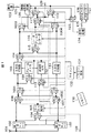
図1は、本発明の実施例としてのテレビジョン受信機の構成例を示す図である。
図1において、101はアンテナ、102は選局手段としての第1のチューナ、103は同じく第2のチューナ、104、106、107、1001、1002、109、111、114、115、1003、1004、117、118、119、123は切換え手段としての切換え回路、105はゴースト低減手段としてのゴースト低減回路、108は3次元YC分離手段としての3次元YC分離回路、110は同じくフレームメモリ、112は巡回型ノイズリデューサ(以下、巡回型NR回路という)、113は2次元YC分離回路、116は記録再生手段としてのハードディスクレコーダ、120は映像表示処理手段、122は表示部、130は操作用のモード指示手段としてのリモコン、131はリモコン受光部、132は制御手段としてのマイコン(マイクロコンピュータ)、124は音声処理回路、126、127はスピーカー、128はSビデオ入力端子である。かかる構成において、アンテナ101を介して入力された、例えばNTSC規格のテレビジョン信号は、第1のチューナ102及び第2のチューナ103に入力される。第1のチューナ102及び第2のチューナ103では、受信したい所望のテレビ放送番組が選局され、放送番組の複合映像信号と音声信号(以下、複合映像・音声信号という)が出力される。本構成では、第1のチューナ102及び第2のチューナ103におけるテレビ放送番組の選局(チャンネルの選局)はリモコン130により行われる。リモコン130では、チャンネル選局の指示の他、電源の投入・切断、ハードディスクレコーダ116における録画、再生、停止等の指示操作を行う。該リモコン130においては、必要な指示操作をコマンド信号に変換し、該コマンド信号を赤外線に変調して出力する。この変調信号はリモコン受光部131に入力され、リモコン受光部131はこの変調信号から操作コマンド信号を再生する。この再生されたコマンド信号は、制御手段としてのマイクロコンピュータ(以下、マイコンという)132へ入力される。マイコン132はテレビジョン受信機内の各ブロックを制御する。マイコン132からの制御に基づき、第1のチューナ102で選局された複合映像・音声信号は、切換え回路104の入力端子Aと切換え回路106の入力端子Aとに入力される。また、マイコン132からの制御に基づき、第2のチューナ103で選局された複合映像・音声信号は、切換え回路104の入力端子Bと切換え回路107の入力端子Bとに入力される。
【0007】
切換え回路104では、第1のチューナ102から出力される複合映像・音声信号、または第2のチューナ103から出力される複合映像・音声信号のいずれか一方が選択されて出力される。該切換え回路104の選択制御はマイコン132により行われる。切換え回路104から出力された複合映像・音声信号はゴースト低減回路105に入力される。ゴースト低減回路105においては、複合映像信号からゴースト成分が検出され低減化される。音声信号は該ゴースト低減回路105においては信号処理されずに出力される。ゴースト低減回路105から出力される複合映像・音声信号は、切換え回路106の入力端子Bと切換え回路107の入力端子Aとに入力される。
切換え回路106では、第1のチューナ102から出力された複合映像・音声信号、またはゴースト低減回路105から出力された複合映像・音声信号のいずれか一方が選択されて出力される。該切換え回路106の選択制御もマイコン132により行われる。切換え回路106から出力された複合映像・音声信号は、切換え回路1001の入力端子Aと切換え回路1002の入力端子Aとにそれぞれ入力される。
【0008】
切換え回路107では、第2のチューナ102から出力された複合映像・音声信号またはゴースト低減回路105から出力された複合映像・音声信号のいずれか一方が選択されて出力される。該切換え回路107の選択制御もマイコン132により行われる。切換え回路107から出力された複合映像・音声信号は、切換え回路1001の入力端子Bと切換え回路1002の入力端子Bとにそれぞれ入力される。切換え回路1001と切換え回路1002ではそれぞれ、入力端子Aには切換え回路106の出力が、また、入力端子Bには切換え回路107の出力が入力されるが、切換動作は逆となるようにマイコン132で制御される。すなわち、切換え回路1001で入力端子Aが選択された場合は、切換え回路1002では入力端子Bが選択される。切換え回路1001と切換え回路1002は、第1のチューナ102と第2のチューナ103のうち任意に選択されたいずれか一方のチューナにおける放送番組の複合映像・音声信号に対し、1系統の3次元YC分離回路108で3次元YC分離処理を行えるようにするための切換え回路である。通常の状態では、切換え回路1001では入力端子Aが、切換え回路1002では入力端子Bが選択されるようになっている。
【0009】
切換え回路1002の出力は2次元YC分離回路113に入力される。2次元YC分離回路113では、ライメモリ等の遅延回路(図示なし)から構成された回路により復号映像信号を輝度信号と色信号とに分離する。音声信号は該2次元YC分離回路113では信号処理されない。
切換え回路1001から出力された複合映像・音声信号は、3次元YC分離回路108に入力される。また、切換え回路109の入力端子Aには切換え回路1001から出力される複合映像が入力される。切換え回路109の入力端子Bには、巡回型ノイズリデューサ回路(以下、巡回型NR回路という)112から出力される輝度信号と色信号とが入力される。切換え回路109では、入力端子Aまたは入力端子Bのいずれか一方が選択されて出力される。該切換え回路109の選択制御もマイコン132により行われる。
【0010】
3次元YC分離回路108は、切換え回路109が入力端子Aを選択する場合に有効に作用する。切換え回路1001から出力された複合映像信号は、切換え回路109の入力端子Aより選択されて出力され、フレームメモリ110に入力される。フレームメモリ110では、複合映像信号を1フレーム遅延させた複合映像信号として出力する。フレームメモリ110から出力された複合映像信号は3次元YC分離回路108に入力される。3次元YC分離回路108では、切換え回路1001から出力された複合映像信号と、フレームメモリ110から出力された1フレーム遅延した複合映像信号とからクロスカラー妨害やドット妨害のない高画質な輝度信号と色信号とが分離されて出力される。音声信号は3次元YC分離回路108では信号処理されない。3次元YC分離回路108から出力された輝度信号と色信号と音声信号(以下、輝度・色・音声信号という)は、切換え回路114の入力端子Aに入力される。
【0011】
一方、Sビデオ入力端子128より入力された輝度信号と色信号と音声信号(以下、Sビデオ信号という)は、切換え回路111の入力端子Aに入力される。該Sビデオ入力端子128は、例えばVTRやDVDプレーヤー等の外部ビデオ機器のSビデオ出力端子に接続される。切換え回路111の入力端子Bには、ハードディスクレコーダ116より再生された出力信号である輝度・色・音声信号が入力される。該切換え回路111においては、入力端子Aまたは入力端子Bから入力された輝度信号、色信号、音声信号のいずれかが選択されて出力される。切換え回路111の選択制御もマイコン132により行われる。
【0012】
切換え回路111から出力される輝度・色・音声信号は、巡回型NR回路112に入力される。本実施例構成においては、ランダムノイズを低減するための巡回型ノイズ低減回路は、巡回型NR回路112と、該巡回型NR回路112の出力が切換え回路109を介して入力され1フレーム遅延した出力を巡回型NR回路112に出力するフレームメモリ110とから構成される。巡回型NR回路112は例えば、特開平10−84552号公報中の図6に記載の構成を有するものとする。巡回型NR回路112は、輝度・色信号に含まれる低域から高域までの周波数のノイズを低減して出力する。該出力としての輝度信号及び色信号は、切換え回路109の入力端子Bに入力される。切換え回路111がマイコン132により選択制御され、該切換え回路111から出力されたSビデオ入力端子128からの輝度信号及び色信号、またはハードディスクレコーダ116で再生された輝度信号及び色信号は、フレームメモリ110に入力される。巡回型NR回路112に入力される輝度信号と、フレームメモリ110から出力される1フレーム遅延した輝度信号との差分から、巡回型NR回路112内部でのフレーム間演算によりノイズ成分が抽出され、該ノイズ成分のゲインを下げたノイズ成分を入力の輝度信号から差し引くことにより、ノイズ低減された輝度信号が出力される。該ノイズ低減された輝度信号は、フレームメモリ110に入力される。次のフレーム間演算においては、前回ノイズ低減された後のデータと比較されるため、徐々にノイズ低減量が増す。これを繰り返すことにより、最終的にはノイズ低減された輝度信号が出力される。また、色信号についても同様である。音声信号は巡回型NR回路112内では信号処理されない。巡回型NR回路112から出力された輝度・色・音声信号は、切換え回路114の入力端子Bと切換え回路117の入力端子Bとに入力される。本実施例構成においては、上記のように、フレームメモリ110は、3次元YC分離回路108と組合せて3次元YC分離機能部を構成した場合は複合映像信号を1フレーム遅延させ、巡回型NR回路112と組合せて輝度信号と色信号のノイズ低減回路を構成した場合は該輝度信号、該色信号それぞれを1フレーム遅延させる。
【0013】
切換え回路114から出力された輝度・色・音声信号は、切換え回路115、切換え回路1003及び切換え回路1004それぞれの入力端子Aに入力される。また、2次元YC分離回路113から出力された輝度・色・音声信号は、切換え回路115、切換え回路1003及び切換え回路1004それぞれの入力端子Bに入力される。切換え回路114、切換え回路115、切換え回路117、切換え回路1003、切換え回路1004における選択制御もマイコン132により行われる。
【0014】
切換え回路1003及び切換え回路1004は、第1のチューナ102で選局された局の放送番組の映像信号と、第2のチューナ103で選局された局の放送番組の映像信号と、ハードディスクレコーダ116で再生された映像信号のうちの2つの映像を表示部122に2画面表示する際、少なくとも1系統の画質改善回路で画質改善処理がなされた所望の放送番組の映像信号、または1系統の2次元YC分離された所望の放送番組の映像信号を、表示部122の画面のうち一方の側に表示させるように切換える。切換え回路1003と切換え回路1004の切換動作は、切換え回路1001と切換え回路1002の場合と同様に、互いに逆となるようにマイコン132で制御される。通常は、切換え回路1003では入力端子Aが、切換え回路1004では入力端子Bが選択される。
【0015】
切換え回路115では、切換え回路114から出力される輝度・色・音声信号かまたは2次元YC分離回路113から出力される輝度・色・音声信号のいずれか一方が選択され、選択された出力信号はハードディスクレコーダ116に入力される。ハードディスクレコーダ116では、入力された輝度・色・音声信号は、ハードディスクレコーダ116内のAD変換器(図示なし)によりAD変換されデジタル信号に変換される。該デジタル信号は、同じくハードディスクレコーダ116内でMPEG符号化処理回路(図示なし)によりデジタル圧縮データに変換され、該圧縮データがファイルとしてハードディスクドライブ(HDD)(図示なし)に書き込まれる。ハードディスクレコーダ116内におけるかかる録画動作は、マイコン132からの録画命令に基づき実行される。同様に、ハードディスクレコーダ116の再生動作も、マイコン132からの再生制御命令に基づき行われる。マイコン132からの再生制御命令を受けると、ハードディスクレコーダ116は、HDDからファイルを読み出してMPEG復号化を行い、輝度・色・音声信号を再生して出力する。その他、ハードディスクレコーダ116の一般的な停止動作や、巻き戻し動作や、早送り等の特殊再生動作や、一時停止動作などの命令もすべてマイコン132から出される。ハードディスクレコーダ116で再生された輝度・色・音声信号は、切換え回路117の入力端子Aと切換え回路111の入力端子Bとにそれぞれ入力される。切換え回路117では、ハードディスクレコーダ116で再生された信号かまたは巡回型NR回路112から出力される信号かのいずれか一方が選択され、該選択された信号は、切換え回路118の入力端子Bと切換え回路119の入力端子Aとにそれぞれ入力される。
【0016】
切換え回路118では、切換え回路1003から出力された輝度・色・音声信号と、切換え回路117から出力された度・色・音声信号とが切換えられる。切換え回路118から出力される輝度信号及び色信号は、映像表示処理回路120の一方の映像入力系統に入力され、音声信号は切換え回路123の入力端子Aに入力される。同様に、切換え回路119では、切換え回路1004から出力された輝度・色・音声信号と、切換え回路117から出力された輝度・色・音声信号とが切換えられる。切換え回路119から出力される輝度信号及び色信号は映像表示処理回路120の他方の映像入力系統に入力され、音声信号は切換え回路123の入力端子Bに入力される。
【0017】
上記のように、映像入力系統を2系統備えた映像表示処理回路120では、入力された2系統の輝度信号及び色信号のうちいずれか一方または両方が選択される。入力された輝度信号及び色信号はそれぞれ、映像表示処理回路120内において、画面サイズの拡大や縮小等のスケーリング処理や2画面表示処理等の映像信号処理がされた後、映像出力端子121から出力され表示部122側に入力される。スケーリング処理では、後段水平方向と垂直方向の画素数や水平同期信号や垂直同期信号が生成される。映像表示処理回路120における2画面表示処理等の制御の選択は、リモコン130からの指示操作に基づき、マイコン132により制御される。一方、音声信号については、切換え回路118から出力される音声信号は切換え回路123の入力端子Aに入力され、切換え回路119から出力される音声信号は切換え回路123の入力端子Bに入力される。切換え回路123から出力される音声信号は音声処理回路124に入力され、該音声処理回路124で音声信号処理が行われた後、音声出力端子125から出力され、ステレオスピーカーであるRスピーカー126とLスピーカー127より音声として出力される。
【0018】
以下、図1の実施例構成における主要部の動作につき説明する。
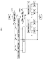
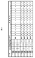
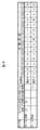
図2〜図9は、図1のテレビジョン受信機の動作の説明図である。図2は裏番組を録画する場合としない場合の動作例のフローを示す図、図3は、設定された各モードの動作を行わせる場合における各切換え回路の端子接続の説明図、図4は、ハードディスクレコーダ116により再生した映像信号から、巡回型ノイズ低減回路によりランダムノイズを低減する場合の、各切換え回路の端子接続の説明図、図5は、同場合における画面切換えの説明図、図6は、第1のチューナ102による放送中の映像と、ハードディスクレコーダ116による再生映像とを2画面表示する場合における各切換え回路の端子接続の説明図、図7は、同場合における画面表示例を示す図、図8は、第1のチューナ102で選局した放送中の映像と、第2のチューナ103で選局した放送中の映像とを2画面表示する場合における各切換え回路の端子接続の説明図、図9は、同場合における画面表示例を示す図である。
【0019】
図2において、ユーザが放送番組を視聴中あるいは視聴していない状態、録画中あるいは録画中でないかにより7つのモード(モード1〜7)に区分している。設定1の処理では、モード1〜モード3の動作を行い、設定2の処理ではモード4の動作を行い、設定3の処理ではモード5の動作を行い、設定4の処理ではモード6の動作を行い、設定5の処理ではモード7の動作を行う。各モードにおける各切換え回路の端子接続状態は図3に示す通りとなる。図2において、まず、ステップS201で裏番組録画か否かを判定する。裏番組録画でなければ、視聴中番組を録画するモード1と、視聴しないで録画するモード2と、視聴のみを行い録画はしないモード3とに区分し、図1実施例構成における各切換え回路の端子接続を、マイコン132による制御により、図3中の設定1の状態に制御する。ステップS201で裏番組録画と判定されれば、ステップS202で録画を画質改善された状態で行う録画画質優先モードか否かを判定する。録画画質優先モードであれば、録画対象の放送番組映像をゴースト低減回路105と3次元YC分離回路108の両方によって画質改善するモード4と、3次元YC分離回路のみで画質改善するモード5とに区分し、モード4では図1の実施例構成における各切換え回路の端子接続を設定2の状態に設定し、モード5では該各切換え回路を設定3の状態に設定する。ステップS202において、録画画質優先モードでなく視聴を画質改善された状態で行う視聴画質優先モードであれば、視聴対象の放送番組映像をゴースト低減回路105と3次元YC分離回路108の両方により画質改善するモード6と、3次元YC分離回路のみで画質改善するモード7とに区分し、モード6では図1の構成における各切換え回路の端子接続を設定4の状態に設定し、モード7では該各切換え回路の端子接続を設定5の状態に設定する。
【0020】
図3において、各処理(設定1〜設定5)は、マイコン132により制御する各切換え回路104、106、1001、109、114、107、1002、111、115、117、1003、118、1004、119、123の切換状態を示す。図中、A、Bはそれぞれ、各切換え回路の入力端子A、入力端子Bのうち選択される入力端子を示し、*印は、入力端子A、Bのいずれを選択してもよいことを示す。
以下、各モードにつき説明する。
モード1は、放送番組視聴中に視聴している放送番組を録画する場合である。この場合は、設定1に示すように、図1の構成における各切換え回路の入力端子が切換えられ、第1のチューナ102で選局された放送番組の複合映像・音声信号が、表示部122及びハードディスクレコーダ116に入力されるまでに、ゴースト低減回路105と3次元YC分離回路108を通る。このため、視聴放送番組のゴースト歪みが低減され、かつ、3次元YC分離が行われ、画質改善された状態の分離された輝度・色信号による映像が表示部122に表示され、同時に、ハードディスクレコーダ116で記録される。ハードディスクレコーダ116は、録画しながら同時に再生も可能な構成を備えるものとする。録画しながら再生映像を視聴する場合は、設定1の切換え回路の状態から、切換え回路117を入力端子A側に切換え、切換え回路118を入力端子B側に切換えて、ハードディスクレコーダ116の再生映像信号を映像表示処理回路120に入力し、再生音声信号を音声処理回路124に入力する。
【0021】
モード2は、番組は視聴しないで録画などを行う場合、つまり番組の留守録画等の場合である。モード2の場合は、設定1に示すように、図1の構成における各切換え回路の入力端子が切換えられ、第1のチューナ102で選局された放送番組の複合映像・音声信号がハードディスクレコーダ116に入力されるまでに、ゴースト低減回路105と3次元YC分離回路108を通る。このため、視聴放送番組のゴースト歪みが低減され、かつ、3次元YC分離が行われて、画質改善された状態で分離された輝度・色信号がハードディスクレコーダ116に入力されて記録される。
【0022】
モード3は、録画は行わずに番組を視聴する場合である。この場合は、設定1に示すように、図1の構成における各切換え回路の入力端子が切換えられ、第1のチューナ102で選局された放送番組の複合映像・音声信号が表示部122に入力されるまでに、ゴースト低減回路105と3次元YC分離回路108を通る。このため、視聴放送番組のゴースト歪みが低減され、かつ、3次元YC分離が行われて、画質改善された状態で分離された輝度・色信号が表示部122に表示される。
【0023】
モード4からモード7までは視聴放送番組と録画放送番組が異なる場合のモードである。以下、説明を容易とするため、3次元YC分離処理を行う放送番組を選局するチューナを第1のチューナ102として説明する。
モード4では、設定2に示すように各切換え回路の入力端子が切換えられ、第1のチューナ102で選局された放送番組の複合映像・音声信号は表示部122に入力されるまでに2次元YC分離回路113を通り、第2のチューナ103で選局された録画用の放送番組の複合映像・音声信号はハードディスクレコーダ116に入力されるまでにゴースト低減回路105と3次元YC分離回路108を通る。このため、視聴放送番組の複合映像・音声信号は2次元YC分離されて表示部122に表示され、また、録画放送番組の複合映像・音声信号はゴースト低減処理と3次元YC分離処理による画質改善がなされる。
【0024】
モード5では、設定3に示すように各切換え回路の入力端子が切換えられ、第1のチューナ102で選局された録画用の放送番組の複合映像・音声信号はハードディスクレコーダ116に入力されるまでに3次元YC分離回路108を通り、第2のチューナ103で選局された放送番組の複合映像・音声信号は表示部122に入力されるまでにゴースト低減回路105と2次元YC分離回路113を通る。このため、録画放送番組の複合映像・音声信号は3次元YC分離処理され、視聴放送番組の複合映像・音声信号はゴースト低減処理と2次元YC分離処理がなされる。
モード6では、設定4に示すように各切換え回路の入力端子が切り換えられ、第1のチューナ102で選局された放送番組の複合映像・音声信号は表示部122に入力されるまでにゴースト低減回路105と3次元YC分離回路108を通り、第2のチューナ103で選局された録画用の放送番組の複合映像・音声信号はハードディスクレコーダ116に入力されるまでに2次元YC分離回路113を通る。このため、視聴放送番組の複合映像・音声信号はゴースト低減処理と3次元YC分離処理とが行われ、録画放送番組の複合映像・音声信号は2次元YC分離処理がなされる。
モード7では、設定5に示すように各切換え回路の入力端子が切換えられ、第1のチューナ102で選局された放送番組の複合映像・音声信号は表示部122に入力されるまでに3次元YC分離回路108を通り、第2のチューナ103で選局された録画用の放送番組の複合映像・音声信号はハードディスクレコーダ116に入力されるまでにゴースト低減回路105と2次元YC分離回路113を通る。このため、視聴放送番組の複合映像・音声信号は3次元YC分離処理され、録画放送番組の複合映像・音声信号はゴースト低減処理と2次元YC分離処理とがなされる。
【0025】
ここで、モード4とモード5、モード6とモード7では、視聴する放送番組と録画する放送番組のどちらにゴースト低減を行うのかをモードで固定したが、ゴースト低減回路105ではゴースト波の数や大きさを検出することができるため、ゴーストの有無によって視聴放送番組と録画放送番組のどちらで使用するかをマイコン132に判断させ、該マイコン132で、切換え回路104、切換え回路106、切換え回路107、切換え回路1001及び切換え回路1002を制御して切換えるようにしてもよい。音声信号については、特別な信号処理がなされず、表示部122の画面に表示する放送番組映像に対応する音声をRスピーカー126、Lスピーカー127より音声に変換されて出力される。ハードディスクレコーダ116に映像信号(輝度信号、色信号)を記録する際には、当然、映像に対応した音声信号が記録される。
【0026】
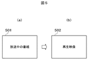
図4及び図5は、ハードディスクレコーダ116により再生中の映像信号に対し、巡回型NR回路112とフレームメモリ110との組合せを用いてランダムノイズを低減する場合の動作説明図である。ここでは、第1のチューナ102で受信した放送番組の映像信号に対し、ゴースト低減処理と3次元YC分離処理とを行い画質改善された状態で表示部122に表示し視聴していた場合(図5(a)の画面501に示す画面)から、表示を切換えて、ランダムノイズが低減された状態のハードディスクレコーダ116の再生出力を視聴する場合(図5(b)の画面502に示す画面)にする場合の例につき述べる。
【0027】
放送番組を表示部122にて表示して視聴する際は、図4のモード8に示す設定6のように、各切換え回路の入力端子が切換えられ、第1のチューナ102の放送番組の複合映像・音声信号はゴースト低減処理と3次元YC分離処理が行われて、画質改善された放送番組を視聴する。ユーザがリモコン130による再生操作を行うことで、マイコン132はハードディスクレコーダ116に再生命令を送り、同時に、図4の設定7に示すように、各切換え回路の入力端子を切換え、切換え回路111と切換え回路109はそれぞれ入力端子B側に切換えて、ハードディスクレコーダ116からの再生出力を、巡回型NR回路112とフレームメモリ110とから成る巡回型ノイズ低減回路に導き、ここでノイズ低減された出力をさらに、切換え回路117、118を通して映像表示処理回路120に入力し、さらに表示部122に送って映像表示する。
【0028】
ランダムノイズを低減する巡回型ノイズ低減回路は、巡回型NR回路112と、巡回型NR回路112の出力が切換え回路109を介して入力され1フレーム遅延した出力を巡回型NR回路112に出力するフレームメモリ110とで構成され、設定7のように各切換え回路を設定することにより、ハードディスクレコーダ116からの再生信号を低域から高域までのランダムノイズを低減した映像を表示部122で表示可能にする。このため、前述のモード1またはモード2による設定により放送番組映像のゴーストを低減し、さらに3次元YC分離処理によりクロスカラー妨害やドット妨害がない状態に画質改善された輝度信号と色信号をハードディスクレコーダ116に録画していた場合には、ゴースト低減処理と3次元YC分離処理による画質改善に加え、さらに、ランダムノイズ低減による画質改善も可能となる。
【0029】
このように、受信中の放送番組に対して直接同時には3次元YC分離機能とフレーム巡回型ノイズ低減機能を使用することはできないが、録画した映像信号に対しては、再生時にフレーム巡回型ノイズ低減回路を使用することができる。これにより、さらに画質改善された映像信号を生成することができる。なお、上記説明ではハードディスクレコーダ116の再生出力に対してランダムノイズ低減がなされる場合につき述べたが、ランダムノイズ低減は、Sビデオ入力端子128に接続される外部の録画再生装置の再生出力に対しても可能である。3次元YC分離処理により画質改善した信号を録画終了後、再生時には、3次元YC分離処理に使用したフレームメモリ110と、巡回型NR回路112とで構成されるフレーム巡回型ノイズ低減回路によるランダムノイズ低減効果により、低域から高域まで十分な範囲のノイズが低減されるため、クロクカラー妨害やドット妨害が発生しないだけでなく、ランダムノイズが十分に抑圧された映像信号を表示部に表示することができる。
【0030】
上記実施例構成によれば、1系統の画質改善回路しか有しない構成であっても、画質改善された状態で視聴したい、画質改善された状態で録画したい、ランダムノイズを低減したいなどの要望に応じた条件で視聴や録画や再生を行うことが可能となる。また、Sビデオ出力端子129からは、上記の画質改善された輝度信号と色信号とを出力することができるため、本実施例のテレビジョン受信機を他の映像表示装置や録画機器に接続した場合にも、画質改善された映像信号での表示や録画が可能となる。
【0031】
図6及び図7は、第1のチューナ102による放送番組とハードディスクレコーダ116の再生映像とを2画面表示する場合の説明図である。以下、モード10とモード11における切換え回路の切換処理の形態例につき説明する。本説明では、説明の便宜上、第1のチューナ102の放送番組映像を画面左側に表示し、ハードディスクレコーダ116の再生映像を画面右側に表示して、スピーカーから出力する音声をハードディスクレコーダ116の再生音声から第1のチューナの放送番組音声に切換える動作につき述べる。
【0032】
モード10では、第1のチューナ102で受信選局した放送番組の映像信号は、ゴースト低減処理と2次元YC分離処理がなされた状態で、また、ハードディスクレコーダ116による再生信号はランダムノイズが低減された状態で、それぞれ表示部122に2画面表示される。モード11では、第1のチューナ102で受信選局した放送番組の映像信号は、ゴースト低減処理と3次元YC分離処理がなされた状態で、また、ハードディスクレコーダ116による再生信号はそのまま出力されて、それぞれ表示部122に2画面表示される。スピーカーからは、モード10ではハードディスクレコーダ116の再生音声信号による音声が出力され、モード11ではその逆で、第1のチューナ102で受信選局した放送番組の音声信号による音声が出力される。
【0033】
ハードディスクレコーダ116による再生音声信号の音声をRスピーカー126とLスピーカー127より出力する場合には、各切換え回路は図6に示すモード10のように設定される。つまり、図6中の設定8のように各切換え回路の入力端子が切換えられると、切換え回路104は入力端子A側に切換えられるため、第1のチューナ102で受信された放送番組の複合映像・音声信号は、ゴースト低減回路105に入力されてゴースト低減される。さらに、切換え回路107は入力端子A側に、切換え回路1002は入力端子B側に切換えられるため、該複合映像・音声信号は、2次元YC分離回路113に入力されて2次元YC分離処理がなされる。2次元YC分離回路113から出力される輝度信号及び色信号により表示部122の画面左側に表示を行うために、切換え回路1003が入力端子B側に、切換え回路118が入力端子A側に切換えられる。該輝度信号及び色信号は、切換え回路1003、切換え回路118を経て映像表示処理回路120の一方の信号処理系に入力され、図7(a)のように、表示部122の画面左側に第1のチューナ102の放送番組映像701が表示される。音声信号は切換え回路123の入力端子A側に入力される。ハードディスクレコーダ116から再生される再生輝度・色・音声信号は、切換え回路111と切換え回路109とがともに入力端子B側に切換えられるため、巡回型NR回路112とフレームメモリ110から成る巡回型ノイズ低減回路を経てランダムノイズが低減される。ランダムノイズが低減されたハードディスクレコーダ116の再生輝度・色・音声信号は、切換え回路117が入力端子B側に、切換え回路119が入力端子A側に切換えられるため、切換え回路117、切換え回路119を経て伝送され、このうち輝度信号と色信号は映像表示処理回路120のもう一方の信号処理系に入力され、図7(a)のように表示部122の画面右側に再生映像702が表示される。音声信号は切換え回路123の入力端子B側に入力される。モード10では、音声の切換え回路123は入力端子B側に切換えられるため、音声としてはハードディスクレコーダ116で再生された音声信号による音声が出力される。なお、図7(a)に示すように、例えば、放送番組映像701と再生映像702とを2画面表示している場合には、音声を出力する方の映像の画面に♪の記号を付すものとする。
【0034】
放送番組映像の音声信号による音声をRスピーカー126とLスピーカー127とから出力する場合には、図6に示すモード11のように設定される。つまり、図6中のモード11における設定9のように各切換え回路の入力端子が切換えられると、第1のチューナ102で受信された放送番組の複合映像・音声信号は、モード10の場合と同様に、ゴースト低減されるが、モード11では、切換え回路106が入力端子B側に、切換え回路1001が入力端子A側に、切換え回路109が入力端子A側に切換えられるため、該第1のチューナ102で受信された放送番組の複合映像・音声信号は、3次元YC分離回路108に入力され、3次元YC分離処理が行われる。3次元YC分離回路108から出力された輝度・色・音声信号は、切換え回路114と切換え回路1003とがともに入力端子A側に切換えられるため、切換え回路118を経て伝送され、このうち輝度信号と色信号は映像表示処理回路120の一方の信号処理系に入力され、図7(b)のように表示部122の画面左側に放送番組映像703が表示される。また、音声信号は切換え回路123の入力端子A側に入力される。
【0035】
ハードディスクレコーダ116で再生された再生輝度・色・音声信号は、切換え回路117と切換え回路119とでともに入力端子Aが選択されるため、切換え回路117、切換え回路119を経て伝送され、このうち輝度信号と色信号は映像表示処理回路120のもう一方の信号処理系に直接入力され、図7(b)のように表示部122の画面右側に再生映像704が表示される。また、音声信号は切換え回路123の入力端子B側に入力される。モード11では音声の切換え回路123は入力端子Aに切換えられるため、音声としては放送番組音声が出力される。この場合は、ハードディスクレコーダ116の再生映像信号はランダムノイズは低減されない。音声を出して視聴する方の映像はゴースト低減処理と3次元YC分離処理がなされて画質改善された放送番組映像である。
以上のように放送番組映像とハードディスクレコーダ116の再生映像との2画面表示の場合は、リモコン130により、左右の画面のうち音声を出力する方の映像、つまり主に番組を視聴する方の映像を画質改善して表示部122に表示することができる。
【0036】
図8及び図9は、第1のチューナ102及び第2のチューナ102で受信した放送番組の映像信号を2画面表示する場合の説明図である。以下、モード12とモード13における切換え回路の切換処理の形態例につき述べる。本説明では、説明の便宜上、第1のチューナ102の放送番組映像を表示部122の画面左側に表示し、第2のチューナ103の放送番組映像を画面右側に表示し、スピーカーから出力する音声を第1のチューナ102の放送番組音声から第2のチューナ103の放送番組音声に切り換える動作につき述べる。
【0037】
モード12では、第1のチューナ102で受信選局した放送番組の映像信号に対しては、モード11の場合と同様、ゴースト低減処理と3次元YC分離処理がなされ、第2のチューナ103で受信選局した放送番組の映像信号に対しては2次元YC分離処理がなされ、表示部122に2画面表示される。モード13では、その逆の画質設定がなされる。スピーカーからは、モード12では、モード11の場合と同様に第1のチューナ102で受信選局した放送番組の音声信号による音声が、モード13ではその逆で、第2のチューナ103で受信選局した放送番組の音声信号による音声が出力される。
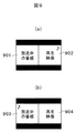
モード12では、第1のチューナ102にて受信された放送番組の複合映像・音声信号の流れはモード11の場合と同様である。図8のモード12に示す設定10のように、各切換え回路の入力端子が切換えられると、第1のチューナ102にて受信された放送番組の複合映像・音声信号は、切換え回路104(入力端子A側)、ゴースト低減回路105、切換え回路106(入力端子B側)、切換え回路1001(入力端子A側)、3次元YC分離回路108を経て、ゴースト低減処理と3次元YC分離処理とが行われて画質改善され、さらに、切換え回路114(入力端子A側)、切換え回路1003(入力端子A側)、切換え回路118(入力端子A側)を経て、輝度信号及び色信号は映像表示処理回路120の一方の信号処理系に入力され、図9(a)のように表示部122の画面左側に第1のチューナの放送番組映像901が表示される。音声信号は切換え回路123の入力端子A側に入力される。また、第2のチューナ103にて受信された放送番組の複合映像・音声信号は、切換え回路107が入力端子B側に、切換え回路1002が入力端子B側に切換えられるため、2次元YC分離回路113に入力されて2次元YC分離処理が行われる。2次元YC分離回路113から出力される輝度・色・音声信号は、切換え回路1004が入力端子B側に、切換え回路119が入力端子B側に切換えられるため、切換え回路1004、切換え回路119を通り、そのうち輝度信号及び色信号は映像表示処理回路120のもう一方の信号処理系に入力され、図9(a)のように表示部122の画面右側に第2のチューナの放送番組映像902が表示される。音声信号は切換え回路123の入力端子B側に入力される。モード12では音声の切換え回路123は入力端子A側に切換えられるため、音声としては第1のチューナの放送番組音声が出力される。
【0038】
図8のモード13に示す設定9のように各切換え回路の端子接続が切換えられると、切換え回路104と切換え回路1001とがともに入力端子B側に切換えられ、切換え回路106と切換え回路1002とがともに入力端子A側に切換えられるため、第1のチューナ102にて受信された放送番組の複合映像・音声信号は、2次元YC分離回路113に入力されて2次元YC分離処理される。表示部122の画面左側に表示させるために、切換え回路1003は入力端子B側に、切換え回路1004は入力端子A側に切換えられる。このため、2次元YC分離回路113から出力された輝度・色・音声信号は切換え回路1003、切換え回路118を経て伝送され、このうち、輝度信号と色信号は映像表示処理回路120の一方の信号処理系に入力され、図9(b)のように表示部122の画面左側に第1のチューナの放送番組映像903が表示される。音声信号は切換え回路123の入力端子A側に入力される。また、第2のチューナ103にて受信された放送番組の複合映像・音声信号は、切換え回路104が入力端子B側に切換えられるため、ゴースト低減回路105に入力されてゴースト低減される。切換え回路106と切換え回路107がともに入力端子A側に切換えられ、切換え回路1001が入力端子B側に切換えられ、切換え回路1002が入力端子A側に切換えられるため、ゴースト低減回路105から出力される複合映像・音声信号は3次元YC分離回路108に入力されて3次元YC分離処理される。3次元YC分離回路108から出力された輝度・色・音声信号は、切換え回路114、切換え回路1004、及び切換え回路119を経て伝送され、このうち輝度信号と色信号は、映像表示処理回路120のもう一方の信号処理系に入力され、表示部122の画面右側に第2のチューナの放送番組映像904が表示される。また、音声信号は切換え回路123の入力端子B側に入力される。モード13では、音声信号の切換え回路123は入力端子B側に切換えられるため、音声としては第2のチューナで選局された放送番組の音声信号による音声が出力される。
【0039】
上記実施例構成によれば、例えばHDDのような録画再生装置を備えたテレビジョン受信機において、1系統の画質改善回路しか備えていなくとも、各切換え回路をマイコン132より制御して切換えることにより、ユーザの要望に応じた画質で視聴や録画や再生を行うことができる。
なお、画質改善手段は、例えば輪郭補正手段など他の手段を含んで構成されてもよい。
【0040】
【発明の効果】
本発明によれば、例えば1系統の画質改善回路しか備えていなくとも、画質改善した映像信号で視聴や録画や再生が可能なテレビジョン受信機を提供することができる。
【図面の簡単な説明】
【図1】本発明の実施例としてのテレビジョン受信機の構成例を示す図である。
【図2】図1の構成において裏番組を録画する場合としない場合の動作例のフローを示す図である。
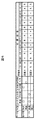
【図3】各モードの動作を行わせる場合における各切換え回路の端子接続の説明図である。
【図4】再生映像信号からランダムノイズを低減する場合の各切換え回路の端子接続の説明図である。
【図5】放送中の映像の画面から再生映像の画面に切換える場合の説明図である。
【図6】放送中の映像と再生映像とに基づき2画面表示する場合における各切換え回路の端子接続の説明図である。
【図7】図6の場合の画面表示例を示す図である。
【図8】放送中の2つの映像を2画面表示する場合における各切換え回路の端子接続の説明図である。
【図9】図8の場合の画面表示例を示す図である。
【符号の説明】
101…アンテナ、 102…第1のチューナ、 103…第2のチューナ、104、106、107、1001、1002、109、111、114、115、1003、1004、117、118、119、123…切換え回路、 105…ゴースト低減回路、 108…3次元YC分離回路、 110…フレームメモリ、 112…巡回型NR回路、 113…2次元YC分離回路、 116…ハードディスクレコーダ、 120…映像表示処理装置、 122…表示部、 124…音声処理回路、 130…リモコン、 131…リモコン受光部、132…マイコン。
[0001]
TECHNICAL FIELD OF THE INVENTION
The present invention relates to a television receiver having a recording / reproducing function or a multi-screen display function.
[0002]
[Prior art]
Conventional techniques related to the image quality improvement technique of the present invention include, for example, JP-A-10-84552 (Patent Document 1), JP-A-6-113323 (Patent Document 2), and JP-A-2001-292422 ( There is one described in Patent Document 3). Japanese Unexamined Patent Publication No. Hei 10-84552 discloses that a video signal is separated into and out of a frequency band containing many aliasing noise components or chroma components, cyclic noise reduction is performed outside the band, and repetitive noise reduction is performed inside the band. A configuration for performing acyclic noise reduction is described. Japanese Unexamined Patent Publication No. Hei 6-113323 discloses a three-dimensional YC separation technique for effectively operating a frame memory not only when a standard composite video signal but also a non-standard composite video signal is input. A configuration in which a noise component of a luminance signal is extracted from a separated output by a low-pass filter and the noise component is subtracted from an input video signal to perform motion adaptive noise reduction even for a non-standard composite video signal is described. Have been. Japanese Patent Application Laid-Open No. 2001-292422 discloses an image reproducing apparatus technology using a hard disk drive (hereinafter, referred to as an HDD), which can switch and display a currently received image and a reproduced image based on a previously recorded image signal. Technology is described.
Also in conventional products, the three-dimensional YC separation circuit is generally provided fixedly for only one video signal system.
Further, as a conventional technique related to the multi-screen display of the present invention, as is performed in a large-screen television such as a wide-screen television, one screen area is divided into two right and left, and each of the divided screen areas is divided into two parts. For example, there is a technique for displaying different images.
[0003]
[Patent Document 1]
JP-A-10-84552 (paragraph numbers 0026 to 0037, FIGS. 1 and 3)
[Patent Document 2]
JP-A-6-113323 (paragraph numbers 0014 to 0024, FIG. 1)
[Patent Document 3]
JP 2001-292422 A
[0004]
[Problems to be solved by the invention]
The circuits for improving image quality, particularly the three-dimensional YC separation circuit, in each of the above-mentioned prior arts are configured using many special filters and frame memories, resulting in high costs. For this reason, the conventional television receiver is provided only in one of the video signal systems. In addition, even in a television receiver having a recording / reproducing function, the image quality improving process is configured to be fixed to one of the currently viewed program and the program to be recorded / reproduced. Switching was not possible. Also, in the case of displaying a plurality of screens, the screen on which the image quality improvement processing is performed is fixed, and the image quality improvement processing cannot be performed on another screen.
An object of the present invention is to provide a television receiver, which has an image quality improvement circuit, particularly a three-dimensional YC separation circuit, for example, even in a configuration having only one three-dimensional YC separation circuit in view of the above-described conventional technology. On the other hand, the purpose is to enable the image quality improvement processing to be performed by arbitrary switching, and to enable the image quality improvement processing to be performed on any screen even in the parallel multiple screen display.
An object of the present invention is to provide a technique capable of solving such a problem.
[0005]
[Means for Solving the Problems]
In order to solve the above problems, in the present invention, a television receiver having a recording / reproducing function is basically provided with a ghost reduction unit for reducing distortion caused by a ghost wave, and / or a three-dimensional YC separation unit. Image quality improving means, video signal recording / reproducing means, switching means for switching the transmission path of the video signal, and control means for controlling the switching means. The transmission path is switched by the switching means to improve the image quality. A video signal selected from the video signals of a plurality of tuned stations is input to the processing means or the recording / reproducing means, or a non-input state is set. Further, as a television receiver having a multi-screen display function, basically, a parallel multi-screen video display processing means for performing signal processing for simultaneously displaying a plurality of screens on a display unit, Sound output means for outputting sound by any one of them, ghost reduction means, image quality improvement means provided with one or both of three-dimensional YC separation means, and switching means for switching the connection state of the image quality improvement means. Control means for controlling the switching means and the audio output means, and by controlling the switching means and the audio output means, inputs a video signal of a screen from which audio is output among a plurality of screens displayed simultaneously to the image quality improving means. The image quality improvement processing is performed. Specifically, a television receiver having a recording / reproducing function includes: (1) a ghost reducing unit (corresponding embodiment: reference numeral 105) for reducing distortion caused by a ghost wave from a selected video signal, and a frame memory. Image quality improving means (corresponding embodiment: reference numeral 105, and / or three-dimensional YC separation unit (corresponding embodiment: reference numerals 108, 110)) for separating a video signal into a luminance signal and a chrominance signal using the same. 108, 110, 112, 113), recording / reproducing means for recording or reproducing a video signal (corresponding embodiment: reference numeral 116), and switching means for switching the transmission path of the video signal including the image quality improving means and the recording / reproducing means. (Applicable embodiment: Reference numerals 104, 106, 107, 1001, 1002, 109, 111, 114, 115, 1003, 1004, 117, 118, 119) 123), and control means for controlling the switching means (corresponding embodiment: reference numeral 132). By switching the transmission path under the control of the switching means, at least one of the video signals of a plurality of stations selected. An input or a non-input of the video signal of one station to the image quality improving means or the recording / reproducing means can be selected. (2) Ghost reduction means (corresponding embodiment: reference numeral 105) for reducing distortion caused by a ghost wave from a selected video signal, and three-dimensional YC for separating the video signal into a luminance signal and a color signal using a frame memory Image quality improving means (corresponding embodiment: reference numerals 105, 108, 110, 112, 113) provided with one or both of separation means (pertinent embodiment: reference numerals 108, 110) and recording or reproduction of a video signal Recording / reproducing means (corresponding embodiment: reference numeral 116) and switching means for switching the video signal transmission path including the image quality improving means and the recording / reproducing means (corresponding embodiment: reference numerals 104, 106, 107, 1001, 1002, 109) , 111, 114, 115, 1003, 1004, 117, 118, 119, 123) and control means for controlling the switching means. 132), and by switching the transmission path under the control of the switching means, the video signal of the first station to be watched and the second video signal to be recorded among the video signals of the plurality of stations selected, The input and non-input to the image quality improving means can be selected. (3) Tuning means for selecting a received video signal (corresponding embodiment: reference numerals 102 and 103) and ghost reduction means for reducing distortion due to ghost waves from the selected video signal (corresponding embodiment: reference numeral 105) ) And a three-dimensional YC separating means (applicable embodiment: reference numerals 108 and 110) for separating a video signal into a luminance signal and a chrominance signal using a frame memory, or both. Examples: Reference numerals 105, 108, 110, 112, 113), recording / reproducing means for recording or reproducing a video signal (applicable embodiment: reference numeral 116), and the connection state of the image quality improving means to the channel selecting means side, Switching means for switching the connection / disconnection of the recording / reproducing means to / from the image quality improving means (applicable embodiment: reference numerals 104, 106, 107, 1001, 1002, 109, 11) , 114, 115) and control means (corresponding embodiment: reference numeral 132) capable of controlling the switching means. The image quality improving means is tuned to the tuning means by the switching means. When the video signal of at least one of the video signals of the plurality of stations is connected to be input, and the recording / reproducing means is disconnected from the image quality improving means, the one station is The video signal is transmitted to the display unit without passing through the recording / reproducing means after one or both of the processing for reducing the distortion due to the ghost wave and the three-dimensional YC separation processing are performed in the image quality improving means. I do. (4) Tuning means for selecting a received video signal (corresponding embodiment: reference numerals 102 and 103) and ghost reduction means for reducing distortion due to ghost waves from the selected video signal (corresponding embodiment: reference numeral 105) ) And a three-dimensional YC separating means (applicable embodiment: reference numerals 108 and 110) for separating a video signal into a luminance signal and a chrominance signal using a frame memory, or both. Examples: Reference numerals 105, 108, 110, 112, 113), recording / reproducing means for recording or reproducing a video signal (applicable embodiment: reference numeral 116), and the connection state of the image quality improving means to the channel selecting means side, Switching means for switching the connection / disconnection of the recording / reproducing means to / from the image quality improving means (applicable embodiment: reference numerals 104, 106, 107, 1001, 1002, 109, 11) , 114, 115) and control means (corresponding embodiment: reference numeral 132) capable of controlling the switching means. The image quality improving means is tuned to the tuning means by the switching means. When the video signal of at least one of the video signals of the plurality of stations is connected to be input and the recording / reproducing means is connected to the image quality improving means, The video signal is recorded by the recording / reproducing means after one or both of the ghost wave distortion reduction processing and the three-dimensional YC separation processing are performed by the image quality improving means. (5) Tuning means for selecting a received video signal (applicable embodiment: reference numerals 102 and 103) and ghost reducing means for reducing distortion due to ghost waves from the selected video signal (applicable embodiment: reference numeral 105) ) And a three-dimensional YC separating means (applicable embodiment: reference numerals 108 and 110) for separating a video signal into a luminance signal and a chrominance signal using a frame memory, or both. Example: Reference numerals 105, 108, 110, 112, and 113), recording / reproducing means for recording or reproducing a video signal (applicable embodiment: Reference numeral 116), and a frame cyclic type for reducing random noise of a reproduced video signal Noise reduction means (corresponding embodiments: reference numerals 110 and 112), the connection state of the image quality improvement means to the channel selection means side, and the recording / reproducing operation to the image quality improvement means side Switching means for switching connection / disconnection of the switch (applicable embodiment: reference numerals 104, 106, 107, 1001, 1002, 109, 111, 114, 115) and control means for controlling at least the switch means (applicable embodiment: reference numeral 132), mode instructing means for sending a mode instruction signal to the control means (corresponding embodiment: reference numeral 130), and video display processing means for performing display processing of a video signal including screen size processing (corresponding embodiment: reference numeral 120) ), And a display unit for displaying an image based on the output from the image display processing means (applicable embodiment: reference numeral 122). The switching means causes the image quality improving means to select the channel selecting means. Connected so that the video signal of at least one of the video signals of the plurality of stations is input, and wherein the recording / reproducing means is connected to the image quality improving means. In this state, the image signal of the one station is recorded by the recording / reproducing means after one or both of the processing for reducing the distortion due to the ghost wave and the three-dimensional YC separation processing are performed by the image quality improving means. Then, the reproduced video signal is displayed on the display unit after the random noise is reduced by the frame cyclic noise reduction unit. Further, as a television receiver having a multi-screen display function, (6) channel selecting means for selecting a received video signal (applicable embodiment: reference numerals 102 and 103); A multi-screen video display processing means for performing signal processing for simultaneously displaying a plurality of screens on the display unit based on the video, an audio output means for outputting sound on any one of the plurality of screens, and a selected video signal Ghost reduction means (corresponding embodiment: reference numeral 105) for reducing distortion due to ghost waves, and / or three-dimensional YC separation means for separating a video signal into a luminance signal and a chrominance signal using a frame memory. Image quality improving means (corresponding embodiment: reference numerals 105, 108, 110, 112, 113) and a switching means for switching the connection state of the image quality improving means to the channel selecting means side. (Corresponding embodiment: reference numerals 104, 106, 107, 1001, 1002, 109, 111) and control means for controlling the switching means and the audio output means (corresponding embodiment: reference numeral 132); A video signal of a screen from which audio is output among the plurality of screens displayed simultaneously is input to the image quality improving means under the control of the audio output means; After either or both of the dimensional YC separation processing is performed, the data is transmitted to the display unit side. Further, as a video signal processing circuit for a television receiver having a recording / reproducing function, (7) a ghost reducing unit (corresponding embodiment: reference numeral 105) for reducing distortion caused by a ghost wave from a selected video signal; An image quality improvement circuit (corresponding embodiment: including one or both of a three-dimensional YC separation unit (corresponding embodiment: reference numerals 108 and 110) for separating a video signal into a luminance signal and a chrominance signal using a frame memory. Reference numerals 105, 108, 110, 112, and 113), a recording / reproducing circuit that performs signal processing for recording or reproducing a video signal (corresponding embodiment: reference numeral 116), and the image quality improving circuit and the recording / reproducing circuit. Switching section for switching the transmission path of the video signal (applicable embodiment: reference numerals 104, 106, 107, 1001, 1002, 109, 111, 114, 115, 1003, 10 4, 117, 118, 119, 123) and a control circuit (corresponding embodiment: reference numeral 132) for controlling the switching means, and the channel is selected by switching the transmission path under the control of the switching unit. An input or a non-input of the video signal of at least one of the video signals of the plurality of stations to the image quality improving circuit or the recording / reproducing circuit can be selected.
[0006]
BEST MODE FOR CARRYING OUT THE INVENTION
Hereinafter, embodiments of the present invention will be described with reference to the drawings.
FIG. 1 is a diagram illustrating a configuration example of a television receiver as an embodiment of the present invention.
In FIG. 1, 101 is an antenna, 102 is a first tuner as a tuning means, 103 is a second tuner, 104, 106, 107, 1001, 1002, 109, 111, 114, 115, 1003, 1004, Reference numerals 117, 118, 119 and 123 denote switching circuits as switching means, 105 denotes a ghost reduction circuit as ghost reduction means, 108 denotes a three-dimensional YC separation circuit as three-dimensional YC separation means, 110 denotes a frame memory, and 112 denotes a cyclic memory. Type noise reducer (hereinafter referred to as a cyclic NR circuit), 113 is a two-dimensional YC separation circuit, 116 is a hard disk recorder as recording / reproducing means, 120 is video display processing means, 122 is a display unit, and 130 is an operation mode instruction. Remote control as means, 131 is a remote control light receiving section, 132 is control means To the microcomputer, the audio processing circuit 124, 126 and 127 speakers, 128 are S-video input terminal. In such a configuration, for example, a television signal of the NTSC standard input via the antenna 101 is input to the first tuner 102 and the second tuner 103. In the first tuner 102 and the second tuner 103, a desired television broadcast program to be received is selected, and a composite video signal and an audio signal (hereinafter, a composite video / audio signal) of the broadcast program are output. In this configuration, selection of a television broadcast program (selection of a channel) in the first tuner 102 and the second tuner 103 is performed by the remote controller 130. The remote controller 130 performs instructions such as turning on / off the power, recording, reproducing, and stopping the hard disk recorder 116, in addition to instructions for channel selection. The remote controller 130 converts a necessary instruction operation into a command signal, modulates the command signal into infrared rays, and outputs the infrared rays. The modulated signal is input to the remote control light receiving unit 131, and the remote control light receiving unit 131 reproduces an operation command signal from the modulated signal. The reproduced command signal is input to a microcomputer (hereinafter, referred to as a microcomputer) 132 as control means. The microcomputer 132 controls each block in the television receiver. Based on the control from the microcomputer 132, the composite video / audio signal selected by the first tuner 102 is input to the input terminal A of the switching circuit 104 and the input terminal A of the switching circuit 106. The composite video / audio signal selected by the second tuner 103 under the control of the microcomputer 132 is input to the input terminal B of the switching circuit 104 and the input terminal B of the switching circuit 107.
[0007]
The switching circuit 104 selects and outputs either the composite video / audio signal output from the first tuner 102 or the composite video / audio signal output from the second tuner 103. Selection control of the switching circuit 104 is performed by the microcomputer 132. The composite video / audio signal output from the switching circuit 104 is input to the ghost reduction circuit 105. In the ghost reduction circuit 105, a ghost component is detected and reduced from the composite video signal. The audio signal is output without signal processing in the ghost reduction circuit 105. The composite video / audio signal output from the ghost reduction circuit 105 is input to the input terminal B of the switching circuit 106 and the input terminal A of the switching circuit 107.
The switching circuit 106 selects and outputs one of the composite video / audio signal output from the first tuner 102 and the composite video / audio signal output from the ghost reduction circuit 105. The selection control of the switching circuit 106 is also performed by the microcomputer 132. The composite video / audio signal output from switching circuit 106 is input to input terminal A of switching circuit 1001 and input terminal A of switching circuit 1002, respectively.
[0008]
The switching circuit 107 selects and outputs one of the composite video / audio signal output from the second tuner 102 and the composite video / audio signal output from the ghost reduction circuit 105. Selection control of the switching circuit 107 is also performed by the microcomputer 132. The composite video / audio signal output from switching circuit 107 is input to input terminal B of switching circuit 1001 and input terminal B of switching circuit 1002, respectively. In the switching circuit 1001 and the switching circuit 1002, the output of the switching circuit 106 is inputted to the input terminal A and the output of the switching circuit 107 is inputted to the input terminal B, respectively. Is controlled by That is, when the input terminal A is selected by the switching circuit 1001, the input terminal B is selected by the switching circuit 1002. Switching circuit 1001 and switching circuit 1002 provide one system of three-dimensional YC for a composite video / audio signal of a broadcast program in one of tuners arbitrarily selected from first tuner 102 and second tuner 103. This is a switching circuit for enabling the separation circuit 108 to perform three-dimensional YC separation processing. In a normal state, the input terminal A is selected in the switching circuit 1001, and the input terminal B is selected in the switching circuit 1002.
[0009]
The output of the switching circuit 1002 is input to the two-dimensional YC separation circuit 113. The two-dimensional YC separation circuit 113 separates the decoded video signal into a luminance signal and a chrominance signal using a circuit including a delay circuit (not shown) such as a live memory. The audio signal is not processed by the two-dimensional YC separation circuit 113.
The composite video / audio signal output from the switching circuit 1001 is input to the three-dimensional YC separation circuit 108. The composite video output from the switching circuit 1001 is input to the input terminal A of the switching circuit 109. A luminance signal and a chrominance signal output from a cyclic noise reducer circuit (hereinafter referred to as a cyclic NR circuit) 112 are input to an input terminal B of the switching circuit 109. In the switching circuit 109, one of the input terminal A and the input terminal B is selected and output. The selection control of the switching circuit 109 is also performed by the microcomputer 132.
[0010]
The three-dimensional YC separation circuit 108 works effectively when the switching circuit 109 selects the input terminal A. The composite video signal output from the switching circuit 1001 is selected and output from the input terminal A of the switching circuit 109, and is input to the frame memory 110. The frame memory 110 outputs the composite video signal as a composite video signal delayed by one frame. The composite video signal output from the frame memory 110 is input to the three-dimensional YC separation circuit 108. In the three-dimensional YC separation circuit 108, a high-quality luminance signal free from cross color interference and dot interference is obtained from the composite video signal output from the switching circuit 1001 and the composite video signal output from the frame memory 110 and delayed by one frame. The color signal is separated and output. The audio signal is not processed by the three-dimensional YC separation circuit 108. The luminance signal, the chrominance signal, and the audio signal (hereinafter, referred to as luminance / color / audio signal) output from the three-dimensional YC separation circuit 108 are input to an input terminal A of the switching circuit 114.
[0011]
On the other hand, the luminance signal, the chrominance signal, and the audio signal (hereinafter, referred to as S video signal) input from the S video input terminal 128 are input to the input terminal A of the switching circuit 111. The S-video input terminal 128 is connected to an S-video output terminal of an external video device such as a VTR or a DVD player. To the input terminal B of the switching circuit 111, a luminance / color / audio signal which is an output signal reproduced from the hard disk recorder 116 is input. The switching circuit 111 selects and outputs one of a luminance signal, a chrominance signal, and an audio signal input from the input terminal A or the input terminal B. The selection control of the switching circuit 111 is also performed by the microcomputer 132.
[0012]
The luminance / color / audio signal output from the switching circuit 111 is input to the cyclic NR circuit 112. In the configuration of the present embodiment, the cyclic noise reduction circuit for reducing random noise includes a cyclic NR circuit 112 and an output obtained by inputting the output of the cyclic NR circuit 112 via the switching circuit 109 and delaying the output by one frame. To the cyclic NR circuit 112. It is assumed that the cyclic NR circuit 112 has, for example, a configuration shown in FIG. 6 in JP-A-10-84552. The cyclic NR circuit 112 reduces noise in frequencies from low to high frequencies included in the luminance / color signal and outputs the reduced noise. The output luminance signal and color signal are input to the input terminal B of the switching circuit 109. The switching circuit 111 is selectively controlled by the microcomputer 132, and the luminance signal and color signal from the S-video input terminal 128 output from the switching circuit 111 or the luminance signal and color signal reproduced by the hard disk recorder 116 are stored in the frame memory 110. Is entered. From the difference between the luminance signal input to the cyclic NR circuit 112 and the luminance signal delayed by one frame output from the frame memory 110, a noise component is extracted by an inter-frame operation inside the cyclic NR circuit 112. By subtracting the noise component obtained by lowering the gain of the noise component from the input luminance signal, a noise-reduced luminance signal is output. The noise signal whose noise has been reduced is input to the frame memory 110. In the next inter-frame calculation, the amount of noise reduction gradually increases because the data is compared with the data after the previous noise reduction. By repeating this, a luminance signal with noise reduced is finally output. The same applies to color signals. The audio signal is not processed in the cyclic NR circuit 112. The luminance / color / audio signal output from the cyclic NR circuit 112 is input to the input terminal B of the switching circuit 114 and the input terminal B of the switching circuit 117. In the configuration of the present embodiment, as described above, the frame memory 110 delays the composite video signal by one frame when the three-dimensional YC separation function unit is configured in combination with the three-dimensional YC separation circuit 108, and the cyclic NR circuit When a noise reduction circuit for a luminance signal and a chrominance signal is configured in combination with 112, the luminance signal and the chrominance signal are each delayed by one frame.
[0013]
The luminance / color / audio signal output from the switching circuit 114 is input to the input terminals A of the switching circuit 115, the switching circuit 1003, and the switching circuit 1004. The luminance, color, and audio signals output from the two-dimensional YC separation circuit 113 are input to the input terminals B of the switching circuit 115, the switching circuit 1003, and the switching circuit 1004. The selection control in the switching circuit 114, the switching circuit 115, the switching circuit 117, the switching circuit 1003, and the switching circuit 1004 is also performed by the microcomputer 132.
[0014]
The switching circuit 1003 and the switching circuit 1004 include a video signal of a broadcast program of a station selected by the first tuner 102, a video signal of a broadcast program of a station selected by the second tuner 103, and a hard disk recorder 116. When two images of the video signals reproduced in step 2 are displayed on the display unit 122 on two screens, the video signal of a desired broadcast program subjected to image quality improvement processing by at least one image quality improvement circuit or one system of two video signals The video signal of the desired broadcast program separated by the dimension YC is switched to be displayed on one side of the screen of the display unit 122. The switching operation of the switching circuit 1003 and the switching circuit 1004 is controlled by the microcomputer 132 so as to be opposite to each other, as in the case of the switching circuit 1001 and the switching circuit 1002. Normally, the input terminal A is selected in the switching circuit 1003, and the input terminal B is selected in the switching circuit 1004.
[0015]
In the switching circuit 115, either the luminance / color / audio signal output from the switching circuit 114 or the luminance / color / audio signal output from the two-dimensional YC separation circuit 113 is selected, and the selected output signal is The data is input to the hard disk recorder 116. In the hard disk recorder 116, the input luminance / color / audio signal is AD-converted by an AD converter (not shown) in the hard disk recorder 116 and converted into a digital signal. The digital signal is similarly converted into digital compressed data by an MPEG encoding processing circuit (not shown) in the hard disk recorder 116, and the compressed data is written as a file to a hard disk drive (HDD) (not shown). Such a recording operation in the hard disk recorder 116 is executed based on a recording instruction from the microcomputer 132. Similarly, the reproduction operation of the hard disk recorder 116 is also performed based on a reproduction control command from the microcomputer 132. Upon receiving a reproduction control command from the microcomputer 132, the hard disk recorder 116 reads a file from the HDD, performs MPEG decoding, reproduces a luminance / color / audio signal, and outputs the reproduced signal. In addition, the microcomputer 132 also issues commands such as a general stop operation, a rewind operation, a special reproduction operation such as fast forward, and a pause operation of the hard disk recorder 116. The luminance / color / audio signal reproduced by the hard disk recorder 116 is input to the input terminal A of the switching circuit 117 and the input terminal B of the switching circuit 111, respectively. In the switching circuit 117, either the signal reproduced by the hard disk recorder 116 or the signal output from the cyclic NR circuit 112 is selected, and the selected signal is switched to the input terminal B of the switching circuit 118. The signal is input to the input terminal A of the circuit 119.
[0016]
The switching circuit 118 switches between the luminance / color / audio signal output from the switching circuit 1003 and the degree / color / audio signal output from the switching circuit 117. The luminance signal and the color signal output from the switching circuit 118 are input to one video input system of the video display processing circuit 120, and the audio signal is input to the input terminal A of the switching circuit 123. Similarly, the switching circuit 119 switches between the luminance / color / audio signal output from the switching circuit 1004 and the luminance / color / audio signal output from the switching circuit 117. The luminance signal and the color signal output from the switching circuit 119 are input to the other video input system of the video display processing circuit 120, and the audio signal is input to the input terminal B of the switching circuit 123.
[0017]
As described above, in the video display processing circuit 120 including two video input systems, one or both of the input two-system luminance signal and color signal are selected. The input luminance signal and color signal are output from the video output terminal 121 after being subjected to video processing such as scaling processing such as enlargement or reduction of the screen size or two-screen display processing in the video display processing circuit 120. The data is input to the display unit 122 side. In the scaling processing, the number of pixels in the subsequent horizontal and vertical directions, a horizontal synchronization signal, and a vertical synchronization signal are generated. Selection of control such as two-screen display processing in the video display processing circuit 120 is controlled by the microcomputer 132 based on an instruction operation from the remote controller 130. On the other hand, as for the audio signal, the audio signal output from the switching circuit 118 is input to the input terminal A of the switching circuit 123, and the audio signal output from the switching circuit 119 is input to the input terminal B of the switching circuit 123. The audio signal output from the switching circuit 123 is input to an audio processing circuit 124, and after the audio signal processing is performed by the audio processing circuit 124, the audio signal is output from an audio output terminal 125. The sound is output from the speaker 127.
[0018]
The operation of the main part in the configuration of the embodiment of FIG.
2 to 9 are explanatory diagrams of the operation of the television receiver in FIG. FIG. 2 is a diagram showing a flow of an operation example in a case where a counterprogram is recorded, and FIG. 3 is an explanatory diagram of terminal connection of each switching circuit when an operation in each set mode is performed, and FIG. FIG. 5 is an explanatory diagram of terminal connection of each switching circuit when random noise is reduced by a cyclic noise reduction circuit from a video signal reproduced by the hard disk recorder 116. FIG. 5 is an explanatory diagram of screen switching in the same case. FIG. 7 is an explanatory diagram of terminal connection of each switching circuit in a case where a video being broadcast by the first tuner 102 and a video reproduced by the hard disk recorder 116 are displayed on two screens. FIG. 7 shows a screen display example in the same case. FIGS. 8A and 8B show a case where a broadcast video selected by the first tuner 102 and a broadcast video selected by the second tuner 103 are displayed on two screens. Illustration of terminal connection of the switching circuit, FIG. 9 is a view showing a screen display example in the same case.
[0019]
In FIG. 2, the broadcast program is classified into seven modes (modes 1 to 7) depending on whether the user is viewing or not viewing the broadcast program, or recording or not recording. In the processing of setting 1, the operation of mode 1 to mode 3 is performed, in the processing of setting 2, the operation of mode 4 is performed, in the processing of setting 3, the operation of mode 5 is performed, and in the processing of setting 4, the operation of mode 6 is performed. Then, in the processing of the setting 5, the operation of the mode 7 is performed. The terminal connection state of each switching circuit in each mode is as shown in FIG. In FIG. 2, first, in step S201, it is determined whether or not the program is a counter-program recording. If the program is not a counter program recording, the mode is divided into a mode 1 for recording the program being viewed, a mode 2 for recording without viewing, and a mode 3 for recording only for viewing and not recording. The terminal connection is controlled to the state of setting 1 in FIG. If it is determined in step S201 that the program is a counter-program recording, it is determined in step S202 whether or not a recording image quality priority mode in which recording is performed with the image quality improved. In the case of the recording image quality priority mode, there are a mode 4 in which the image quality of the broadcast program video to be recorded is improved by both the ghost reduction circuit 105 and the three-dimensional YC separation circuit 108, and a mode 5 in which the image quality is improved only by the three-dimensional YC separation circuit. In mode 4, the terminal connection of each switching circuit in the embodiment of FIG. 1 is set to the state of setting 2, and in mode 5, each switching circuit is set to the state of setting 3. In step S202, if not the recording quality priority mode, but the viewing quality priority mode in which viewing is performed with the image quality improved, the image quality of the broadcast program video to be viewed is improved by both the ghost reduction circuit 105 and the three-dimensional YC separation circuit 108. In the mode 6, the terminal connection of each switching circuit in the configuration of FIG. 1 is set to the state of the setting 4, and in the mode 7, the mode is set to the setting 4. The terminal connection of the switching circuit is set to the state of setting 5.
[0020]
In FIG. 3, each processing (setting 1 to setting 5) is performed by each switching circuit 104, 106, 1001, 109, 114, 107, 1002, 111, 115, 117, 1003, 118, 1004, 119 controlled by the microcomputer 132. , 123 are shown. In the figure, A and B indicate input terminals selected from the input terminals A and B of each switching circuit, respectively, and an asterisk indicates that either of the input terminals A and B may be selected. .
Hereinafter, each mode will be described.
Mode 1 is for recording a broadcast program being viewed while viewing the broadcast program. In this case, as shown in setting 1, the input terminal of each switching circuit in the configuration of FIG. 1 is switched, and the composite video / audio signal of the broadcast program selected by the first tuner 102 is displayed on the display unit 122 and The signal passes through the ghost reduction circuit 105 and the three-dimensional YC separation circuit 108 before being input to the hard disk recorder 116. For this reason, ghost distortion of the viewing broadcast program is reduced, and three-dimensional YC separation is performed, and an image based on the separated luminance / color signals in a state where the image quality is improved is displayed on the display unit 122, and at the same time, the hard disk recorder Recorded at 116. The hard disk recorder 116 has a configuration capable of simultaneously playing back while recording. When watching the reproduced video while recording, the switching circuit 117 is switched to the input terminal A side and the switching circuit 118 is switched to the input terminal B side from the state of the switching circuit of the setting 1, and the reproduced video signal of the hard disk recorder 116 is switched. Is input to the video display processing circuit 120, and the reproduced audio signal is input to the audio processing circuit 124.
[0021]
Mode 2 is a case where recording or the like is performed without watching the program, that is, a case where the program is recorded and recorded. In the mode 2, as shown in the setting 1, the input terminals of the respective switching circuits in the configuration of FIG. 1 are switched, and the composite video / audio signal of the broadcast program selected by the first tuner 102 is transmitted to the hard disk recorder 116. , Passes through the ghost reduction circuit 105 and the three-dimensional YC separation circuit 108. Therefore, the ghost distortion of the viewing broadcast program is reduced, and the three-dimensional YC separation is performed, and the separated luminance / color signals are input to the hard disk recorder 116 and recorded in an improved image quality state.
[0022]
Mode 3 is for viewing a program without recording. In this case, as shown in setting 1, the input terminal of each switching circuit in the configuration of FIG. 1 is switched, and the composite video / audio signal of the broadcast program selected by the first tuner 102 is input to the display unit 122. By this time, the signal passes through the ghost reduction circuit 105 and the three-dimensional YC separation circuit 108. Therefore, the ghost distortion of the viewing broadcast program is reduced, and the three-dimensional YC separation is performed, and the separated luminance / color signals are displayed on the display unit 122 with the image quality improved.
[0023]
Modes 4 to 7 are modes when the viewing broadcast program and the recorded broadcast program are different. Hereinafter, a tuner that selects a broadcast program to be subjected to the three-dimensional YC separation processing will be described as a first tuner 102 for ease of description.
In mode 4, the input terminals of the switching circuits are switched as shown in setting 2, and the composite video / audio signal of the broadcast program selected by the first tuner 102 is two-dimensionally input to the display unit 122. The ghost reduction circuit 105 and the three-dimensional YC separation circuit 108 pass through the YC separation circuit 113 until the composite video / audio signal of the broadcast program for recording selected by the second tuner 103 is input to the hard disk recorder 116. Pass. Therefore, the composite video / audio signal of the viewing broadcast program is two-dimensionally YC separated and displayed on the display unit 122, and the composite video / audio signal of the recorded broadcast program is improved in image quality by ghost reduction processing and three-dimensional YC separation processing. Is made.
[0024]
In mode 5, the input terminals of the respective switching circuits are switched as shown in setting 3, and the composite video / audio signal of the broadcast program for recording selected by the first tuner 102 is input to the hard disk recorder 116. The ghost reduction circuit 105 and the two-dimensional YC separation circuit 113 pass through the three-dimensional YC separation circuit 108 before the composite video / audio signal of the broadcast program selected by the second tuner 103 is input to the display unit 122. Pass. Therefore, the composite video / audio signal of the recorded broadcast program is subjected to three-dimensional YC separation processing, and the composite video / audio signal of the viewing broadcast program is subjected to ghost reduction processing and two-dimensional YC separation processing.
In mode 6, the input terminals of the respective switching circuits are switched as shown in setting 4, and the composite video / audio signal of the broadcast program selected by the first tuner 102 is reduced in ghost before being input to the display unit 122. After passing through the circuit 105 and the three-dimensional YC separation circuit 108, the composite video / audio signal of the broadcast program for recording selected by the second tuner 103 passes through the two-dimensional YC separation circuit 113 before being input to the hard disk recorder 116. Pass. Therefore, a ghost reduction process and a three-dimensional YC separation process are performed on the composite video / audio signal of the viewing broadcast program, and a two-dimensional YC separation process is performed on the composite video / audio signal of the recorded broadcast program.
In mode 7, the input terminals of the respective switching circuits are switched as shown in setting 5, and the composite video / audio signal of the broadcast program selected by the first tuner 102 is three-dimensionally input to the display unit 122. The ghost reduction circuit 105 and the two-dimensional YC separation circuit 113 pass through the YC separation circuit 108 before the composite video / audio signal of the broadcast program for recording selected by the second tuner 103 is input to the hard disk recorder 116. Pass. Therefore, the composite video / audio signal of the viewed broadcast program is subjected to three-dimensional YC separation processing, and the composite video / audio signal of the recorded broadcast program is subjected to ghost reduction processing and two-dimensional YC separation processing.
[0025]
Here, in modes 4 and 5, and in modes 6 and 7, it is fixed in which mode the ghost is reduced for the broadcast program to be viewed or the broadcast program to be recorded. Since the size can be detected, the microcomputer 132 causes the microcomputer 132 to determine whether to use the broadcast program or the recorded broadcast program based on the presence or absence of a ghost. The microcomputer 132 uses the switching circuit 104, the switching circuit 106, and the switching circuit 107. The switching may be performed by controlling the switching circuit 1001 and the switching circuit 1002. As for the audio signal, no special signal processing is performed, and the audio corresponding to the broadcast program video displayed on the screen of the display unit 122 is converted into audio from the R speaker 126 and the L speaker 127 and output. When a video signal (luminance signal, color signal) is recorded on the hard disk recorder 116, an audio signal corresponding to the video is naturally recorded.
[0026]
FIGS. 4 and 5 are explanatory diagrams of an operation in a case where random noise is reduced by using a combination of the cyclic NR circuit 112 and the frame memory 110 for a video signal being reproduced by the hard disk recorder 116. Here, the ghost reduction process and the three-dimensional YC separation process are performed on the video signal of the broadcast program received by the first tuner 102 to display and view the image on the display unit 122 in a state where the image quality is improved (FIG. 5 (a), the display is switched, and the reproduction output of the hard disk recorder 116 with the random noise reduced is viewed (the screen 502 shown in FIG. 5 (b)). An example of such a case will be described.
[0027]
When the broadcast program is displayed and viewed on the display unit 122, the input terminal of each switching circuit is switched as in the setting 6 shown in the mode 8 in FIG. A ghost reduction process and a three-dimensional YC separation process are performed on the audio signal to view a broadcast program with improved image quality. When the user performs a reproduction operation using the remote controller 130, the microcomputer 132 sends a reproduction command to the hard disk recorder 116, and at the same time, switches the input terminal of each switching circuit and switches to the switching circuit 111 as shown in setting 7 in FIG. The circuit 109 switches to the input terminal B side, and guides the reproduction output from the hard disk recorder 116 to a cyclic noise reduction circuit including a cyclic NR circuit 112 and a frame memory 110, and further reduces the noise-reduced output. Are input to the video display processing circuit 120 through the switching circuits 117 and 118, and are further sent to the display unit 122 for video display.
[0028]
The cyclic noise reduction circuit that reduces random noise includes a cyclic NR circuit 112 and a frame that outputs the output of the cyclic NR circuit 112 to the cyclic NR circuit 112 after being input by way of the switching circuit 109 and delayed by one frame. By setting each switching circuit as in the setting 7 with the memory 110, the reproduction signal from the hard disk recorder 116 can be displayed on the display unit 122 as an image in which random noise from low to high frequencies is reduced. I do. For this reason, the ghost of the broadcast program image is reduced by the setting in the mode 1 or the mode 2 described above, and the luminance signal and the chrominance signal whose image quality is improved by the three-dimensional YC separation processing so that there is no cross color disturbance or dot disturbance are recorded on the hard disk. When the video is recorded on the recorder 116, the image quality can be improved by the random noise reduction in addition to the image quality improvement by the ghost reduction processing and the three-dimensional YC separation processing.
[0029]
As described above, the three-dimensional YC separation function and the frame recursive noise reduction function cannot be used simultaneously and directly with the broadcast program being received, but the recorded video signal cannot be replayed with the frame recursive noise reduction function during reproduction. A reduction circuit can be used. Thereby, a video signal with further improved image quality can be generated. In the above description, the case where random noise reduction is performed on the reproduction output of the hard disk recorder 116 has been described. However, the random noise reduction is performed on the reproduction output of the external recording / reproducing apparatus connected to the S-video input terminal 128. It is possible. After recording of the signal whose image quality has been improved by the three-dimensional YC separation processing, at the time of reproduction, random noise is generated by a frame cyclic noise reduction circuit composed of a frame memory 110 used for the three-dimensional YC separation processing and a cyclic NR circuit 112 during reproduction. Because the noise reduction effect reduces noise in a sufficient range from low to high frequencies, not only does black and white interference occur, but also displays video signals with sufficiently suppressed random noise on the display unit. Can be.
[0030]
According to the configuration of the above-described embodiment, even if the configuration has only one system of image quality improvement circuits, there is a demand for viewing / listening with improved image quality, recording with improved image quality, and reducing random noise. Viewing, recording, and playback can be performed under appropriate conditions. Further, since the luminance signal and the chrominance signal whose image quality has been improved can be output from the S-video output terminal 129, the television receiver of this embodiment is connected to another video display device or recording device. Also in this case, display and recording with a video signal with improved image quality can be performed.
[0031]
FIG. 6 and FIG. 7 are explanatory diagrams of a case where a broadcast program by the first tuner 102 and a video reproduced by the hard disk recorder 116 are displayed on two screens. Hereinafter, an example of the mode of the switching process of the switching circuit in the mode 10 and the mode 11 will be described. In this description, for convenience of explanation, the broadcast program video of the first tuner 102 is displayed on the left side of the screen, the reproduced video of the hard disk recorder 116 is displayed on the right side of the screen, and the audio output from the speaker is reproduced by the hard disk recorder 116. The operation of switching from the first to the broadcast program audio of the first tuner will be described.
[0032]
In mode 10, the video signal of the broadcast program selected and received by the first tuner 102 is subjected to the ghost reduction processing and the two-dimensional YC separation processing, and the reproduction signal from the hard disk recorder 116 is reduced in random noise. In this state, two screens are displayed on the display unit 122 respectively. In mode 11, the video signal of the broadcast program received and selected by the first tuner 102 is subjected to the ghost reduction processing and the three-dimensional YC separation processing, and the reproduction signal from the hard disk recorder 116 is output as it is. Each is displayed on the display unit 122 in two screens. In mode 10, the sound by the reproduced sound signal of the hard disk recorder 116 is output from the speaker, and in mode 11, the sound is output by the sound signal of the broadcast program received and selected by the first tuner 102 in mode 11.
[0033]
When the audio of the audio signal reproduced by the hard disk recorder 116 is output from the R speaker 126 and the L speaker 127, each switching circuit is set as in mode 10 shown in FIG. That is, when the input terminal of each switching circuit is switched as in setting 8 in FIG. 6, the switching circuit 104 is switched to the input terminal A side, so that the composite video / video of the broadcast program received by the first tuner 102 is output. The audio signal is input to the ghost reduction circuit 105 and is reduced in ghost. Further, since the switching circuit 107 is switched to the input terminal A side and the switching circuit 1002 is switched to the input terminal B side, the composite video / audio signal is input to the two-dimensional YC separation circuit 113 and subjected to two-dimensional YC separation processing. You. The switching circuit 1003 is switched to the input terminal B side and the switching circuit 118 is switched to the input terminal A side in order to display on the left side of the screen of the display unit 122 by the luminance signal and the color signal output from the two-dimensional YC separation circuit 113. . The luminance signal and the chrominance signal are input to one of the signal processing systems of the video display processing circuit 120 via the switching circuit 1003 and the switching circuit 118, and the first signal is displayed on the left side of the screen of the display unit 122 as shown in FIG. The broadcast program image 701 of the tuner 102 is displayed. The audio signal is input to the input terminal A of the switching circuit 123. Since the switching circuit 111 and the switching circuit 109 are both switched to the input terminal B side for the reproduced luminance / color / audio signal reproduced from the hard disk recorder 116, the cyclic noise reduction comprising the cyclic NR circuit 112 and the frame memory 110 is performed. Through the circuit, random noise is reduced. Since the switching circuit 117 is switched to the input terminal B side and the switching circuit 119 is switched to the input terminal A side, the reproduced luminance / color / audio signal of the hard disk recorder 116 in which the random noise has been reduced is transmitted through the switching circuits 117 and 119. The luminance signal and the chrominance signal are input to the other signal processing system of the video display processing circuit 120, and the reproduced video 702 is displayed on the right side of the screen of the display unit 122 as shown in FIG. . The audio signal is input to the input terminal B of the switching circuit 123. In the mode 10, since the audio switching circuit 123 is switched to the input terminal B side, the audio is output by the audio signal reproduced by the hard disk recorder 116. As shown in FIG. 7A, for example, when a broadcast program video 701 and a reproduced video 702 are displayed on two screens, the screen of the video from which audio is output is indicated by a symbol ♪. And
[0034]
When the audio by the audio signal of the broadcast program video is output from the R speaker 126 and the L speaker 127, the mode is set as in mode 11 shown in FIG. That is, when the input terminal of each switching circuit is switched as in setting 9 in mode 11 in FIG. 6, the composite video / audio signal of the broadcast program received by the first tuner 102 is the same as in mode 10. In mode 11, the switching circuit 106 is switched to the input terminal B side, the switching circuit 1001 is switched to the input terminal A side, and the switching circuit 109 is switched to the input terminal A side. The composite video / audio signal of the broadcast program received at 102 is input to a three-dimensional YC separation circuit 108, where a three-dimensional YC separation process is performed. The luminance / color / audio signal output from the three-dimensional YC separation circuit 108 is transmitted through the switching circuit 118 because both the switching circuit 114 and the switching circuit 1003 are switched to the input terminal A side. The color signal is input to one signal processing system of the video display processing circuit 120, and a broadcast program video 703 is displayed on the left side of the screen of the display unit 122 as shown in FIG. The audio signal is input to the input terminal A of the switching circuit 123.
[0035]
The reproduced luminance / color / audio signal reproduced by the hard disk recorder 116 is transmitted through the switching circuit 117 and the switching circuit 119 because the input terminal A is selected by both the switching circuit 117 and the switching circuit 119. The signal and the color signal are directly input to the other signal processing system of the video display processing circuit 120, and a reproduced video 704 is displayed on the right side of the screen of the display unit 122 as shown in FIG. The audio signal is input to the input terminal B of the switching circuit 123. In mode 11, the audio switching circuit 123 is switched to the input terminal A, so that broadcast program audio is output as audio. In this case, the random noise of the reproduced video signal of the hard disk recorder 116 is not reduced. The video to be output and viewed is a broadcast program video that has been subjected to ghost reduction processing and three-dimensional YC separation processing to improve image quality.
As described above, in the case of the two-screen display of the broadcast program video and the playback video of the hard disk recorder 116, the remote controller 130 uses the left and right screens to output the audio, that is, the video mainly for viewing the program. Can be displayed on the display unit 122 with the image quality improved.
[0036]
FIG. 8 and FIG. 9 are explanatory diagrams of a case where the video signal of the broadcast program received by the first tuner 102 and the second tuner 102 is displayed on two screens. Hereinafter, an example of the mode of the switching process of the switching circuit in the mode 12 and the mode 13 will be described. In this description, for convenience of explanation, the broadcast program video of the first tuner 102 is displayed on the left side of the screen of the display unit 122, the broadcast program video of the second tuner 103 is displayed on the right side of the screen, and the audio output from the speaker is displayed. The operation of switching from the broadcast program audio of the first tuner 102 to the broadcast program audio of the second tuner 103 will be described.
[0037]
In the mode 12, the ghost reduction process and the three-dimensional YC separation process are performed on the video signal of the broadcast program selected and received by the first tuner 102 in the same manner as in the mode 11, and the received signal is received by the second tuner 103. The video signal of the selected broadcast program is subjected to two-dimensional YC separation processing, and is displayed on the display unit 122 on two screens. In the mode 13, the reverse image quality setting is performed. In mode 12, the sound from the audio signal of the broadcast program received and tuned by the first tuner 102 in mode 12 is the same as in mode 11, and vice versa in mode 13; The audio by the audio signal of the broadcast program is output.
In mode 12, the flow of the composite video / audio signal of the broadcast program received by the first tuner 102 is the same as in mode 11. When the input terminal of each switching circuit is switched as in the setting 10 shown in the mode 12 of FIG. 8, the composite video / audio signal of the broadcast program received by the first tuner 102 is switched to the switching circuit 104 (input terminal A), a ghost reduction circuit 105, a switching circuit 106 (input terminal B side), a switching circuit 1001 (input terminal A side), a three-dimensional YC separation circuit 108, and ghost reduction processing and three-dimensional YC separation processing are performed. The image quality is further improved, and the luminance signal and the chrominance signal are passed through a switching circuit 114 (input terminal A side), a switching circuit 1003 (input terminal A side), and a switching circuit 118 (input terminal A side). The signal is input to one of the signal processing systems 120, and the broadcast program video 901 of the first tuner is displayed on the left side of the screen of the display unit 122 as shown in FIG. The audio signal is input to the input terminal A of the switching circuit 123. Also, the composite video / audio signal of the broadcast program received by the second tuner 103 is switched to the input terminal B side by the switching circuit 107 and the input terminal B side by the switching circuit 1002. The data is input to the input terminal 113 to perform a two-dimensional YC separation process. The luminance / color / audio signal output from the two-dimensional YC separation circuit 113 passes through the switching circuit 1004 and the switching circuit 119 because the switching circuit 1004 is switched to the input terminal B side and the switching circuit 119 is switched to the input terminal B side. Among them, the luminance signal and the chrominance signal are input to the other signal processing system of the video display processing circuit 120, and the broadcast program video 902 of the second tuner is displayed on the right side of the screen of the display unit 122 as shown in FIG. Is done. The audio signal is input to the input terminal B of the switching circuit 123. In mode 12, since the audio switching circuit 123 is switched to the input terminal A side, the broadcast program audio of the first tuner is output as the audio.
[0038]
When the terminal connection of each switching circuit is switched as in setting 9 shown in mode 13 in FIG. 8, both switching circuit 104 and switching circuit 1001 are switched to input terminal B side, and switching circuit 106 and switching circuit 1002 are switched. Since both are switched to the input terminal A side, the composite video / audio signal of the broadcast program received by the first tuner 102 is input to the two-dimensional YC separation circuit 113 and subjected to two-dimensional YC separation processing. The switching circuit 1003 is switched to the input terminal B side and the switching circuit 1004 is switched to the input terminal A side so as to display on the left side of the screen of the display unit 122. For this reason, the luminance / color / audio signal output from the two-dimensional YC separation circuit 113 is transmitted through the switching circuit 1003 and the switching circuit 118, and the luminance signal and the color signal are one of the signals of the video display processing circuit 120. The broadcast program image 903 of the first tuner is displayed on the left side of the screen of the display unit 122 as shown in FIG. 9B. The audio signal is input to the input terminal A of the switching circuit 123. Further, the composite video / audio signal of the broadcast program received by the second tuner 103 is input to the ghost reduction circuit 105 and reduced by the ghost because the switching circuit 104 is switched to the input terminal B side. Switching circuit 106 and switching circuit 107 are both switched to input terminal A, switching circuit 1001 is switched to input terminal B, and switching circuit 1002 is switched to input terminal A, so that ghost reduction circuit 105 outputs. The composite video / audio signal is input to the three-dimensional YC separation circuit 108 and subjected to three-dimensional YC separation processing. The luminance, color, and audio signals output from the three-dimensional YC separation circuit 108 are transmitted through a switching circuit 114, a switching circuit 1004, and a switching circuit 119. Among them, the luminance signal and the chrominance signal are transmitted to the video display processing circuit 120. The signal is input to the other signal processing system, and the broadcast program video 904 of the second tuner is displayed on the right side of the screen of the display unit 122. The audio signal is input to the input terminal B of the switching circuit 123. In the mode 13, since the audio signal switching circuit 123 is switched to the input terminal B side, the audio is output as the audio by the audio signal of the broadcast program selected by the second tuner.
[0039]
According to the configuration of the above-described embodiment, for example, in a television receiver having a recording / reproducing device such as an HDD, even if only one system of image quality improvement circuit is provided, each switching circuit is controlled by the microcomputer 132 to perform switching. It is possible to perform viewing, recording, and reproduction with an image quality according to the user's request.
Note that the image quality improving unit may include another unit such as a contour correcting unit.
[0040]
【The invention's effect】
According to the present invention, it is possible to provide a television receiver that can be viewed, recorded, and played back with a video signal whose image quality has been improved, for example, even if only one system has an image quality improvement circuit.
[Brief description of the drawings]
FIG. 1 is a diagram illustrating a configuration example of a television receiver as an embodiment of the present invention.
FIG. 2 is a diagram showing a flow of an operation example in a case where a counterprogram is recorded in the configuration of FIG.
FIG. 3 is an explanatory diagram of terminal connection of each switching circuit when performing operation in each mode.
FIG. 4 is an explanatory diagram of terminal connection of each switching circuit when random noise is reduced from a reproduced video signal.
FIG. 5 is an explanatory diagram in a case where a screen of a video being broadcast is switched to a screen of a reproduced video.
FIG. 6 is an explanatory diagram of terminal connection of each switching circuit when displaying two screens based on a video being broadcast and a reproduced video.
FIG. 7 is a diagram showing a screen display example in the case of FIG. 6;
FIG. 8 is an explanatory diagram of terminal connection of each switching circuit when two images being broadcast are displayed on two screens.
FIG. 9 is a diagram showing a screen display example in the case of FIG. 8;
[Explanation of symbols]
101: antenna, 102: first tuner, 103: second tuner, 104, 106, 107, 1001, 1002, 109, 111, 114, 115, 1003, 1004, 117, 118, 119, 123 ... switching circuit 105: ghost reduction circuit, 108: three-dimensional YC separation circuit, 110: frame memory, 112: cyclic NR circuit, 113: two-dimensional YC separation circuit, 116: hard disk recorder, 120: video display processing device, 122: display , 124: voice processing circuit, 130: remote control, 131: remote control light receiving unit, 132: microcomputer.

Claims (7)

記録再生機能を備えたテレビジョン受信機であって、
選局された映像信号からゴースト波による歪を低減するゴースト低減手段と、フレームメモリを用いて映像信号を輝度信号と色信号とに分離する3次元YC分離手段とのいずれか一方または両方を備えた画質改善手段と、
映像信号を記録または再生する記録再生手段と、
上記画質改善手段及び上記記録再生手段を含む映像信号の伝送路を切換える切換え手段と、
該切換え手段を制御する制御手段と、
を備え、上記切換え手段の制御により上記伝送路を切換えることで、選局された複数局の映像信号のうち少なくとも1つの局の映像信号の、上記画質改善手段または上記記録再生手段に対する入力、非入力を選択可能にした構成を特徴とするテレビジョン受信機。
A television receiver having a recording and reproducing function,
Either one or both of ghost reduction means for reducing distortion due to ghost waves from the selected video signal and three-dimensional YC separation means for separating the video signal into a luminance signal and a chrominance signal using a frame memory Image quality improvement means,
Recording and reproducing means for recording or reproducing a video signal;
Switching means for switching a transmission path of a video signal including the image quality improving means and the recording / reproducing means,
Control means for controlling the switching means;
By switching the transmission path under the control of the switching means, the input / output of the video signal of at least one of the selected video signals to the image quality improving means or the recording / reproducing means can be performed. A television receiver characterized in that input can be selected.
記録再生機能を備えたテレビジョン受信機であって、
選局された映像信号からゴースト波による歪を低減するゴースト低減手段と、フレームメモリを用いて映像信号を輝度信号と色信号とに分離する3次元YC分離手段とのいずれか一方または両方を備えた画質改善手段と、
映像信号を記録または再生する記録再生手段と、
上記画質改善手段及び上記記録再生手段を含む映像信号の伝送路を切換える切換え手段と、
該切換え手段を制御する制御手段と、
を備え、上記切換え手段の制御により上記伝送路を切換えることで、選局された複数局の映像信号のうち視聴する第1の局の映像信号と記録する第2の映像信号の、上記画質改善手段に対する入力、非入力を選択可能にした構成を特徴とするテレビジョン受信機。
A television receiver having a recording and reproducing function,
Either one or both of ghost reduction means for reducing distortion due to ghost waves from the selected video signal and three-dimensional YC separation means for separating the video signal into a luminance signal and a chrominance signal using a frame memory Image quality improvement means,
Recording and reproducing means for recording or reproducing a video signal;
Switching means for switching a transmission path of a video signal including the image quality improving means and the recording / reproducing means,
Control means for controlling the switching means;
And switching the transmission path under the control of the switching means to improve the image quality of the video signal of the first station to be viewed and the video signal of the second station to be recorded among the video signals of the selected stations. A television receiver characterized in that input and non-input to means can be selected.
記録再生機能を備えたテレビジョン受信機であって、
受信した映像信号を選局する選局手段と、
選局された映像信号からゴースト波による歪を低減するゴースト低減手段と、フレームメモリを用いて映像信号を輝度信号と色信号とに分離する3次元YC分離手段とのいずれか一方または両方を備えた画質改善手段と、
映像信号を記録または再生する記録再生手段と、
上記選局手段側に対する上記画質改善手段の接続状態、及び該画質改善手段側に対する上記記録再生手段の接続、非接続を切換える切換え手段と、
該切換え手段を制御可能な制御手段と、
を備え、上記切換え手段により、上記画質改善手段が上記選局手段側に対し、選局された複数局の映像信号のうち少なくとも1つの局の映像信号が入力されるように接続され、かつ、上記記録再生手段が該画質改善手段側に対し非接続状態とされたときは、該1つの局の映像信号が該画質改善手段においてゴースト波による歪の低減処理もしくは3次元YC分離処理のいずれか一方または両方が行われた後上記記録再生手段を経ずに表示部側に伝送される構成としたことを特徴とするテレビジョン受信機。
A television receiver having a recording and reproducing function,
Tuning means for tuning a received video signal;
Either one or both of ghost reduction means for reducing distortion due to ghost waves from the selected video signal and three-dimensional YC separation means for separating the video signal into a luminance signal and a chrominance signal using a frame memory Image quality improvement means,
Recording and reproducing means for recording or reproducing a video signal;
A connection state of the image quality improvement means to the channel selection means side, and a connection means for switching connection / disconnection of the recording / reproduction means to the image quality improvement means side;
Control means capable of controlling the switching means;
The switching means, the image quality improving means is connected to the tuning means side so that the video signal of at least one of the video signals of the selected plurality of stations is input, and When the recording / reproducing means is not connected to the image quality improving means, the image signal of the one station is subjected to either the processing of reducing distortion due to a ghost wave or the processing of three-dimensional YC separation in the image quality improving means. A television receiver characterized in that, after one or both of the operations, the signal is transmitted to the display unit without passing through the recording / reproducing means.
記録再生機能を備えたテレビジョン受信機であって、
受信した映像信号を選局する選局手段と、
選局された映像信号からゴースト波による歪を低減するゴースト低減手段と、フレームメモリを用いて映像信号を輝度信号と色信号とに分離する3次元YC分離手段とのいずれか一方または両方を備えた画質改善手段と、
映像信号を記録または再生する記録再生手段と、
上記選局手段側に対する上記画質改善手段の接続状態、及び該画質改善手段側に対する上記記録再生手段の接続、非接続を切換える切換え手段と、
該切換え手段を制御可能な制御手段と、
を備え、上記切換え手段により、上記画質改善手段が上記選局手段側に対し、選局された複数局の映像信号のうち少なくとも1つの局の映像信号が入力されるように接続され、かつ、上記記録再生手段が該画質改善手段側に対し接続状態とされたときは、該1つの局の映像信号が、該画質改善手段においてゴースト波による歪の低減処理もしくは3次元YC分離処理のいずれか一方または両方が行われた後上記記録再生手段で記録される構成としたことを特徴とするテレビジョン受信機。
A television receiver having a recording and reproducing function,
Tuning means for tuning a received video signal;
Either one or both of ghost reduction means for reducing distortion due to ghost waves from the selected video signal and three-dimensional YC separation means for separating the video signal into a luminance signal and a chrominance signal using a frame memory Image quality improvement means,
Recording and reproducing means for recording or reproducing a video signal;
A connection state of the image quality improvement means to the channel selection means side, and a connection means for switching connection / disconnection of the recording / reproduction means to the image quality improvement means side;
Control means capable of controlling the switching means;
The switching means, the image quality improving means is connected to the tuning means side so that the video signal of at least one of the video signals of the selected plurality of stations is input, and When the recording / reproducing means is connected to the image quality improving means, the video signal of the one station is processed by the image quality improving means to reduce distortion due to ghost waves or to perform three-dimensional YC separation processing. A television receiver characterized in that recording is performed by the recording / reproducing means after one or both are performed.
記録再生機能を備えたテレビジョン受信機であって、
受信した映像信号を選局する選局手段と、
選局された映像信号からゴースト波による歪を低減するゴースト低減手段と、フレームメモリを用いて映像信号を輝度信号と色信号とに分離する3次元YC分離手段とのいずれか一方または両方を備えた画質改善手段と、
映像信号を記録または再生する記録再生手段と、
再生された映像信号のランダムノイズを低減するフレーム巡回型ノイズ低減手段と、
少なくとも、上記選局手段側に対する上記画質改善手段の接続状態、及び該画質改善手段側に対する上記記録再生手段の接続、非接続を切換える切換え手段と、
少なくとも該切換え手段を制御する制御手段と、
該制御手段に対しモード指示信号を送るモード指示手段と、
画面サイズ処理を含む映像信号の表示処理を行う映像表示処理手段と、
該映像表示処理手段からの出力に基づき映像表示を行う表示部と、
を備え、上記切換え手段により、上記画質改善手段が上記選局手段側に対し、選局された複数局の映像信号のうち少なくとも1つの局の映像信号が入力されるように接続され、かつ、上記記録再生手段が該画質改善手段側に対し接続状態とされたとき、該1つの局の映像信号が、該画質改善手段においてゴースト波による歪の低減処理もしくは3次元YC分離処理のいずれか一方または両方が行われた後上記記録再生手段で記録され、再生された映像信号が上記フレーム巡回型ノイズ低減手段でランダムノイズを低減され上記表示部に表示される構成としたことを特徴とするテレビジョン受信機。
A television receiver having a recording and reproducing function,
Tuning means for tuning a received video signal;
Either one or both of ghost reduction means for reducing distortion due to ghost waves from the selected video signal and three-dimensional YC separation means for separating the video signal into a luminance signal and a chrominance signal using a frame memory Image quality improvement means,
Recording and reproducing means for recording or reproducing a video signal;
Frame cyclic noise reduction means for reducing random noise of the reproduced video signal,
At least, a connection state of the image quality improving means to the channel selecting means side, and a switching means for switching connection / non-connection of the recording / reproducing means to the image quality improving means side,
Control means for controlling at least the switching means;
Mode instruction means for transmitting a mode instruction signal to the control means,
Video display processing means for performing video signal display processing including screen size processing,
A display unit that performs video display based on the output from the video display processing unit,
The switching means, the image quality improving means is connected to the tuning means side so that the video signal of at least one of the video signals of the selected plurality of stations is input, and When the recording / reproducing means is connected to the image quality improving means, the video signal of the one station is processed by the image quality improving means to reduce distortion caused by ghost waves or to perform three-dimensional YC separation processing. Or a television characterized in that the video signal recorded by the recording / reproducing means after both are performed and the reproduced video signal is reduced in random noise by the frame cyclic noise reduction means and displayed on the display section. John receiver.
複数画面表示機能を備えたテレビジョン受信機であって、
受信した映像信号を選局する選局手段と、
選局された複数局の映像信号に基づく複数画面を表示部に同時表示するための信号処理を行う並列複数画面映像表示処理手段と、
上記複数画面のうちのいずれかにおいて音声を出力させる音声出力手段と、
選局された映像信号からゴースト波による歪を低減するゴースト低減手段と、フレームメモリを用いて映像信号を輝度信号と色信号とに分離する3次元YC分離手段とのいずれか一方または両方を備えた画質改善手段と、
上記選局手段側に対する上記画質改善手段の接続状態を切換える切換え手段と、
該切換え手段と上記音声出力手段を制御する制御手段と、
を備え、上記切換え手段及び上記音声出力手段の制御により、上記同時表示される複数画面のうち音声が出力される画面の映像信号が上記画質改善手段に入力され、該画質改善手段においてゴースト波による歪の低減処理もしくは3次元YC分離処理のいずれか一方または両方が行われた後表示部側に伝送される構成としたことを特徴とするテレビジョン受信機。
A television receiver having a multi-screen display function,
Tuning means for tuning a received video signal;
Parallel multi-screen video display processing means for performing signal processing for simultaneously displaying a plurality of screens based on the video signals of the selected stations on the display unit,
Audio output means for outputting audio on any of the plurality of screens,
Either one or both of ghost reduction means for reducing distortion due to ghost waves from the selected video signal and three-dimensional YC separation means for separating the video signal into a luminance signal and a chrominance signal using a frame memory Image quality improvement means,
Switching means for switching a connection state of the image quality improving means to the tuning means side;
Control means for controlling the switching means and the audio output means;
Under the control of the switching means and the audio output means, a video signal of a screen from which audio is output among the plurality of simultaneously displayed screens is input to the image quality improving means, and the image quality improving means uses a ghost wave. A television receiver, characterized in that either one or both of a distortion reduction process and a three-dimensional YC separation process are performed and then transmitted to the display unit side.
記録再生機能を備えたテレビジョン受信機用の映像信号処理回路であって、
選局された映像信号からゴースト波による歪を低減するゴースト低減部と、フレームメモリを用いて映像信号を輝度信号と色信号とに分離する3次元YC分離部とのいずれか一方または両方を備えた画質改善回路と、
映像信号を記録または再生するための信号処理を行う記録再生回路と、
上記画質改善回路及び上記記録再生回路を含む映像信号の伝送路を切換える切換え部と、
該切換え手段を制御する制御回路と、
を備え、上記切換え部の制御により上記伝送路を切換えることで、選局された複数局の映像信号のうちの少なくとも1つの局の映像信号の、上記画質改善回路または上記記録再生回路に対する入力、非入力を選択可能にした構成を特徴とする映像信号処理回路。
A video signal processing circuit for a television receiver having a recording and reproducing function,
Either one or both of a ghost reduction unit that reduces distortion caused by a ghost wave from a selected video signal and a three-dimensional YC separation unit that separates the video signal into a luminance signal and a chrominance signal using a frame memory Image quality improvement circuit,
A recording / reproducing circuit that performs signal processing for recording or reproducing a video signal,
A switching unit that switches a transmission path of a video signal including the image quality improvement circuit and the recording / reproduction circuit,
A control circuit for controlling the switching means;
By switching the transmission path under the control of the switching unit, input of the video signal of at least one of the video signals of a plurality of selected stations to the image quality improvement circuit or the recording / reproducing circuit, A video signal processing circuit characterized in that non-input can be selected.
JP2002370378A 2002-12-20 2002-12-20 Video signal processing circuit and television receiver Pending JP2004201225A (en)

Priority Applications (1)

Application Number Priority Date Filing Date Title
JP2002370378A JP2004201225A (en) 2002-12-20 2002-12-20 Video signal processing circuit and television receiver

Applications Claiming Priority (1)

Application Number Priority Date Filing Date Title
JP2002370378A JP2004201225A (en) 2002-12-20 2002-12-20 Video signal processing circuit and television receiver

Publications (1)

Publication Number Publication Date
JP2004201225A true JP2004201225A (en) 2004-07-15

Family

ID=32766315

Family Applications (1)

Application Number Title Priority Date Filing Date
JP2002370378A Pending JP2004201225A (en) 2002-12-20 2002-12-20 Video signal processing circuit and television receiver

Country Status (1)

Country Link
JP (1) JP2004201225A (en)

Cited By (1)

* Cited by examiner, † Cited by third party
Publication number Priority date Publication date Assignee Title
JP2021057901A (en) * 2019-09-30 2021-04-08 ソニー株式会社 Blind legacy video artifact reduction

Cited By (1)

* Cited by examiner, † Cited by third party
Publication number Priority date Publication date Assignee Title
JP2021057901A (en) * 2019-09-30 2021-04-08 ソニー株式会社 Blind legacy video artifact reduction

Similar Documents

Publication Publication Date Title
JP3698221B2 (en) Control method using graphic of simple transmitter for controlling double deck VCR and CD-karaoke system integrated double / wide TV receiver
JP2642925B2 (en) Television receiver
US8675138B2 (en) Method and apparatus for fast source switching and/or automatic source switching
JP3326628B2 (en) Multiplex video television receiver
JPS62159582A (en) Television receiver
US7536089B2 (en) Image signal reproduction apparatus
JP2006135851A (en) Video device incorporated type video display device
KR20040023011A (en) Digital TV system for supporting of film mode and method for the same
JPS63146672A (en) television receiver
JP2009033415A (en) Display system, display control device, display control method, playback device, playback method, and program
JP4447669B2 (en) Video display apparatus and method
KR100188952B1 (en) Image processing device and recording/reproducing method suitable for this device
JP2004201225A (en) Video signal processing circuit and television receiver
KR20100005841A (en) Digital television and digital television system
JP2650246B2 (en) TV receiver
JP3454526B2 (en) Television receiver
KR0144888B1 (en) Double / wide television set with video cassette recorder and CD-OK system
KR0147647B1 (en) OSD changer for double deck video tape recorder and CD / OK system integrated double / wide television receiver
KR0147657B1 (en) Screen automatic setting method of double/wide tv with double-vcr
KR0141150B1 (en) Double deck video tape recorder and CD-OK system integrated double / wide television receiver
KR0144891B1 (en) Double tech wide-screen TV receiver with integrated telephone receiver and telephone receiver
JP2794660B2 (en) TV receiver
JP3543806B2 (en) Television receiver
KR100233389B1 (en) The ipod device of the composite TV receiver
JP4005755B2 (en) Television signal receiver with ghost reduction function