JP2004201328A - Image sensor positioning system and method - Google Patents
Image sensor positioning system and method Download PDFInfo
- Publication number
- JP2004201328A JP2004201328A JP2003421708A JP2003421708A JP2004201328A JP 2004201328 A JP2004201328 A JP 2004201328A JP 2003421708 A JP2003421708 A JP 2003421708A JP 2003421708 A JP2003421708 A JP 2003421708A JP 2004201328 A JP2004201328 A JP 2004201328A
- Authority
- JP
- Japan
- Prior art keywords
- image sensor
- mounting
- adhesive
- mounting surface
- lens mount
- Prior art date
- Legal status (The legal status is an assumption and is not a legal conclusion. Google has not performed a legal analysis and makes no representation as to the accuracy of the status listed.)
- Pending
Links
- 238000000034 method Methods 0.000 title claims abstract description 40
- 239000000853 adhesive Substances 0.000 claims abstract description 71
- 230000001070 adhesive effect Effects 0.000 claims abstract description 71
- 238000004519 manufacturing process Methods 0.000 claims description 4
- 239000011248 coating agent Substances 0.000 abstract 1
- 238000000576 coating method Methods 0.000 abstract 1
- 230000007246 mechanism Effects 0.000 description 15
- 230000003287 optical effect Effects 0.000 description 8
- 238000010586 diagram Methods 0.000 description 4
- 239000006059 cover glass Substances 0.000 description 3
- 238000011109 contamination Methods 0.000 description 2
- 239000011521 glass Substances 0.000 description 2
- BQCADISMDOOEFD-UHFFFAOYSA-N Silver Chemical compound [Ag] BQCADISMDOOEFD-UHFFFAOYSA-N 0.000 description 1
- 230000000712 assembly Effects 0.000 description 1
- 238000000429 assembly Methods 0.000 description 1
- 239000000919 ceramic Substances 0.000 description 1
- 230000008021 deposition Effects 0.000 description 1
- 239000003822 epoxy resin Substances 0.000 description 1
- 238000003754 machining Methods 0.000 description 1
- 230000013011 mating Effects 0.000 description 1
- 229910052751 metal Inorganic materials 0.000 description 1
- 239000002184 metal Substances 0.000 description 1
- 229920000647 polyepoxide Polymers 0.000 description 1
- 230000001737 promoting effect Effects 0.000 description 1
- 230000011514 reflex Effects 0.000 description 1
- 230000000452 restraining effect Effects 0.000 description 1
- 238000007789 sealing Methods 0.000 description 1
- 229910052709 silver Inorganic materials 0.000 description 1
- 239000004332 silver Substances 0.000 description 1
Images


Classifications
-
- H—ELECTRICITY
- H04—ELECTRIC COMMUNICATION TECHNIQUE
- H04N—PICTORIAL COMMUNICATION, e.g. TELEVISION
- H04N23/00—Cameras or camera modules comprising electronic image sensors; Control thereof
- H04N23/50—Constructional details
- H04N23/54—Mounting of pick-up tubes, electronic image sensors, deviation or focusing coils
Landscapes
- Engineering & Computer Science (AREA)
- Multimedia (AREA)
- Signal Processing (AREA)
- Transforming Light Signals Into Electric Signals (AREA)
- Solid State Image Pick-Up Elements (AREA)
- Camera Bodies And Camera Details Or Accessories (AREA)
- Studio Devices (AREA)
Abstract
Description
本発明は、全体として、イメージセンシング装置およびその位置決めの分野に関する。より詳しくは、本発明は、アセンブリ内におけるイメージセンサの位置決めに関する。 The present invention relates generally to the field of image sensing devices and their positioning. More particularly, the invention relates to positioning an image sensor within an assembly.
典型的なイメージセンサアセンブリは、チップキャリヤパッケージのキャビティに、イメージセンシング装置として働く集積回路ダイをシールし、イメージセンシング装置を汚染から保護するためにカバーガラスでキャビティを覆うことによって構成される。イメージセンシング装置の例には、CCDイメージセンサおよびCMOSイメージセンサを含む。イメージセンサアセンブリはその後、光学システムに取付けられ得る。 A typical image sensor assembly is constructed by sealing an integrated circuit die serving as an image sensing device in a cavity of a chip carrier package and covering the cavity with a cover glass to protect the image sensing device from contamination. Examples of the image sensing device include a CCD image sensor and a CMOS image sensor. The image sensor assembly can then be attached to the optical system.
イメージセンサおよび/またはイメージセンサアセンブリの精確な位置決めは、光学システムに最適な焦点位置を与えるために必要とされる。従って、イメージセンサまたはイメージセンサアセンブリを組み立てる、または位置決めするための諸方法が開示されている。 Precise positioning of the image sensor and / or the image sensor assembly is required to give the optical system an optimal focus position. Accordingly, methods for assembling or positioning an image sensor or image sensor assembly are disclosed.
特許文献1は、イメージセンシング装置の切断端面を、キャリヤパッケージの底部を構成する金属板に機械加工された輪郭特徴に機械的に位置づけるために正確な拘束の使用を提起している。 U.S. Pat. No. 6,077,097 proposes the use of precise restraints to mechanically position the cut end of the image sensing device to a contour feature machined into a metal plate that forms the bottom of the carrier package.
共同譲渡されここに参照によって包含される、特許文献2は、イメージセンシング装置と、参照ロケータに外部からアクセス可能なキャリヤパッケージにおける輪郭特徴の集合への正確な拘束のために適応されたキャリヤパッケージとからなるイメージセンサアセンブリを開示しており、ここにおいて、キャリヤパッケージは、輪郭特徴の集合を基準とするキャリヤパッケージ内の位置でイメージセンシング装置を支持する。 U.S. Pat. No. 6,037,045, co-assigned and hereby incorporated by reference, discloses an image sensing device and a carrier package adapted for precise constraint on a set of contour features in a carrier package externally accessible to a reference locator. Discloses an image sensor assembly, wherein the carrier package supports the image sensing device at a location within the carrier package relative to a collection of contour features.
そうした装置または方法はそれぞれの特定の用途においてある程度の成功を収めているかもしれないが、特にレンズマウントアセンブリまたは基準表面に対するイメージセンサの位置決めを簡単にする必要性が引き続き存在している。 Although such devices or methods may have met with some success in each particular application, there remains a need to simplify the positioning of the image sensor, especially with respect to the lens mount assembly or reference surface.
本発明の目的は、イメージセンサを位置決めするシステムおよび方法を提供することである。 It is an object of the present invention to provide a system and method for positioning an image sensor.
本発明の別の目的は、レンズマウントアセンブリに対するイメージセンサの位置決めの当該システムおよび方法を提供することである。 It is another object of the present invention to provide such a system and method for positioning an image sensor with respect to a lens mount assembly.
これらの目的は例示的な事例としてのみ挙げられており、そうした目的は本発明の1つ以上の実施形態を代表し得る。開示した発明によって本質的に達成される他の望ましい目的および利益は、当業者には想起されるか、または明白になるであろう。本発明は、添付された特許請求の範囲によって規定される。 These objects are given only as exemplary cases, and such objects may represent one or more embodiments of the present invention. Other desirable objectives and benefits inherently achieved by the disclosed invention will occur or become apparent to those skilled in the art. The invention is defined by the appended claims.
本発明の1態様によれば、レンズが取り付けられるレンズマウント基準表面にほぼ平行に配置されたほぼ平面の取付表面を備える取付本体に対してイメージセンサを位置決めする方法が提供される。方法は、取付本体を所定位置に位置決めする工程と、取付位置を規定するために、基準表面から取付表面に向けて基準表面にほぼ直角な軸に沿って測定された所定距離を認識する工程と、接着剤を取付表面に塗布する工程と、イメージセンサが取付位置に位置決めされるようにイメージセンサを接着剤に貼着する工程と、接着剤を硬化させてイメージセンサを取付位置で取付表面に確実に取付ける工程とを含む。 According to one aspect of the present invention, there is provided a method of positioning an image sensor with respect to a mounting body having a substantially planar mounting surface disposed substantially parallel to a lens mount reference surface on which a lens is mounted. The method comprises the steps of positioning a mounting body in a predetermined position, and recognizing a predetermined distance measured along an axis substantially perpendicular to the reference surface from the reference surface to the mounting surface to define the mounting position. Applying the adhesive to the mounting surface, attaching the image sensor to the adhesive so that the image sensor is positioned at the mounting position, and curing the adhesive to attach the image sensor to the mounting surface at the mounting position. And a step of securely mounting.
本発明の別の態様によれば、レンズが取り付けられるレンズマウント基準表面にほぼ平行に配置されたほぼ平面の取付表面を備える取付本体に対してイメージセンサを位置決めする方法が提供される。方法は、取付本体を所定位置に位置決めする工程と、イメージセンサにおける識別子を認識する工程と、取付表面に配置されたロケータを認識する工程と、取付位置を規定するために、レンズマウント基準表面から取付表面に向けてレンズマウント基準表面にほぼ直角な軸に沿って測定された所定距離を認識する工程と、接着剤を取付表面に塗布する工程と、平面の向きを規定するために識別子およびロケータを位置合わせする工程と、イメージセンサが平面の向きにあり取付位置に位置決めされるようにイメージセンサを接着剤に貼着する工程と、接着剤を硬化させてイメージセンサを平面の向きで、かつ取付位置で取付表面に確実に取付ける工程とを含む。 According to another aspect of the invention, there is provided a method of positioning an image sensor with respect to a mounting body having a substantially planar mounting surface disposed substantially parallel to a lens mount reference surface on which a lens is mounted. The method includes the steps of: positioning a mounting body at a predetermined position; recognizing an identifier in an image sensor; recognizing a locator disposed on the mounting surface; and defining a mounting position from a lens mount reference surface. Recognizing a predetermined distance measured along an axis substantially perpendicular to the lens mount reference surface toward the mounting surface; applying adhesive to the mounting surface; and an identifier and locator to define the orientation of the plane. Aligning the image sensor, attaching the image sensor to an adhesive so that the image sensor is oriented in a plane and positioned at the mounting position, and curing the adhesive so that the image sensor is oriented in a plane, and Securely attaching to the mounting surface at the mounting position.
本発明のまた別の態様によれば、イメージセンサアセンブリを作成する方法が提供される。方法は、ほぼ平面の取付表面を有するプレートを用意する工程と、プレートを所定位置で固定具に位置決めする工程と、接着剤を取付表面に塗布する工程と、イメージセンサにおける識別子を認識する工程と、取付表面に配置されたロケータを認識する工程と、取付位置を規定するために、基準表面から取付表面に向けて基準表面にほぼ直角な軸に沿って測定された所定距離を認識する工程と、平面の向きを規定するために識別子およびロケータを位置合わせする工程と、イメージセンサが平面の向きにあり取付位置に位置決めされるようにイメージセンサを接着剤に貼着する工程と、接着剤を硬化させてイメージセンサを平面の向きで、かつ取付位置で取付表面に確実に取付ける工程とを含む。 According to yet another aspect of the present invention, there is provided a method of making an image sensor assembly. The method includes the steps of providing a plate having a substantially planar mounting surface, positioning the plate in a fixture at a predetermined location, applying an adhesive to the mounting surface, and recognizing an identifier on the image sensor. Recognizing a locator located on the mounting surface, and recognizing a predetermined distance measured along an axis substantially perpendicular to the reference surface from the reference surface to the mounting surface to define the mounting position. Aligning the identifier and the locator to define the orientation of the plane, attaching the image sensor to the adhesive so that the image sensor is oriented in the plane and positioned at the mounting position, Curing to securely attach the image sensor to the mounting surface in the plane orientation and at the mounting position.
本発明のさらに別の態様によれば、レンズが取り付けられたレンズマウントアセンブリに対してイメージセンサを位置決めするためのシステムが提供される。システムは、レンズマウントアセンブリを所定位置に位置決めするための固定具と、レンズマウントアセンブリはレンズマウント基準表面にほぼ平行に配置されたほぼ平面の取付表面を備えており、取付位置を規定するために、レンズマウント基準表面から取付表面に向けてレンズマウント基準表面にほぼ直角な軸に沿って測定され所定距離を認識するための手段と、接着剤を取付表面に塗布するための手段と、イメージセンサが取付位置に位置決めされるようにイメージセンサを接着剤に貼着するための手段と、接着剤を硬化させてイメージセンサを取付位置で取付表面に確実に取付けるための硬化手段とを含む。 According to yet another aspect of the present invention, there is provided a system for positioning an image sensor with respect to a lens mount assembly having a lens mounted thereon. The system includes a fixture for positioning the lens mount assembly in place, and the lens mount assembly includes a substantially planar mounting surface disposed substantially parallel to the lens mount reference surface and defines a mounting position. Means for recognizing a predetermined distance measured along an axis substantially perpendicular to the lens mount reference surface from the lens mount reference surface to the mounting surface; means for applying an adhesive to the mounting surface; and an image sensor. Means for adhering the image sensor to the adhesive such that the image sensor is positioned at the mounting position, and curing means for curing the adhesive to securely attach the image sensor to the mounting surface at the mounting position.
本発明は、イメージセンサを位置決めするシステムおよび方法を提供する。 The present invention provides systems and methods for positioning an image sensor.
本発明の上述その他の目的、特徴および利益は、添付図面に例示されたように、本発明の好ましい実施形態の以下のより詳細な説明から明白になるはずである。 The above and other objects, features and advantages of the present invention will become apparent from the following more detailed description of preferred embodiments of the invention, as illustrated in the accompanying drawings.
以下は、同一の参照数字が複数の図のそれぞれにおいて同一の構造要素を識別している図面を参照しつつ、本発明の好ましい実施形態の詳細な説明である。 The following is a detailed description of a preferred embodiment of the present invention, with reference to the drawings, in which the same reference numerals identify the same structural elements in each of the multiple figures.
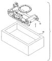
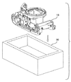
図1はレンズマウントアセンブリ10の分解図を例示している。レンズマウントアセンブリ10は、レンズ14を受けるように適応されたレンズマウント12を含む。レンズマウントアセンブリはさらに、取付本体18に固定されるレンズマウントサポート16、およびシャッタ17を含む。取付本体18は、例えば、カメラのカメラボディまたはリヤボディである。レンズマウント12およびレンズマウントサポート16のアセンブリは、以下、ミラーボックスアセンブリ19と称する。
FIG. 1 illustrates an exploded view of the
レンズマウントアセンブリ10の軸20は、レンズマウント12の表面に配置されたレンズマウント基準表面22にほぼ直角である。図1に例示された通り、軸20は、図示された座標系のz軸に沿って向いている。
The
ここで図2を参照すれば、取付本体18は、イメージセンサ26を支持するためのほぼ平面の取付表面24を含む。取付表面24は、基準表面22にほぼ平行であり、従って軸20にほぼ直角である。
Referring now to FIG. 2, mounting
図3を参照すれば、イメージセンサ26は、イメージセンサ26の一方の表面25が基準表面から所定距離Dに配置されるように、接着剤28によって取付表面24に取付けられる。好ましい実施形態において、基準表面は、図3に例示する通り、レンズマウント12のレンズマウント基準表面22である。従って、検討の簡単のためだけに、本発明の方法は、レンズマウント基準表面22である基準表面に関して開示されるが、当業者は他の基準表面が使用され得ることを認めるであろう。
Referring to FIG. 3, the
さらに図3を参照すれば、レンズマウント基準表面22からの所定距離Dは、イメージセンサ26の取付位置を規定するために認識される。所定距離Dは軸20に沿って取付表面24に向けて測定され、ここで軸20はレンズマウント基準表面22にほぼ直角である。以下で明白になるように、所定距離Dは、イメージセンサ26が取付けられる装置の光学レンズの設計に関係する。例えば、イメージセンサが一眼レフ(SLR)カメラに取付けられる場合、距離Dはカメラプラットフォームの最良焦点距離によって規定される。本発明の1適用の場合、距離Dは45〜50mmの範囲にある。
Still referring to FIG. 3, the predetermined distance D from the lens
接着剤28が取付本体18の取付表面24に塗布され、その後、イメージセンサ26は、イメージセンサ26が接着剤と接触し、軸20に沿って所定距離Dに位置決めされるように、接着剤に貼着される。接着剤は硬化し、イメージセンサ26は所定距離Dで取付表面24に確実に取付けられる。
An
接着剤28は、一定量の接着剤を小出しするために自動接着剤小出し装置によって塗布することができる。そのような接着剤小出しプロセスは、取付表面24上の接着剤28の堆積を制御するための圧力および時間を使用する。イメージセンサ26が取付表面24に確実に取付けられることを保証するために、十分な接着剤28が取付表面24に塗布されなければならないことに留意されたい。不十分な接着剤28が塗布された場合、イメージセンサ26は確実には取付けられないこともある。好ましくは、接着剤28は、接着剤28がイメージセンサ26の少なくとも1つの側端31の少なくとも一部分に付着するように小出しされる。好ましくは、図3に好適な例として示される通り、イメージセンサの端31の少なくとも1つの約25パーセント〜約50パーセントに接触するように十分な接着剤28が付与される。
The
イメージセンサ26が取付表面24に貼着される時にイメージセンサ26と取付表面24との間における接着剤の均一な接触を促進するために、接着剤28をある特定のパターンで取付表面24上に小出しすることができる。例えば、図4を参照すれば、接着剤28は、イメージセンサ26の側端31方向への接着剤の流れを促進するために、放射状パターンで取付表面24に小出しすることができる。
To promote uniform contact of the adhesive between the
接着剤28の例は、好ましくはエイブルスティック(Ablestik)967-1といった銀入り導電性エポキシ樹脂を含む。他の適格な接着剤も当業者には周知であろう。イメージセンサ26は本質的に接着剤28上に浮いており、それにより最良焦点距離に位置決めされ得ることに留意されたい。従って、接着剤が硬化する際に最小の収縮および膨張を呈する接着剤を選定することが肝要である。
Examples of the adhesive 28 include a silver-containing conductive epoxy resin, preferably Ablestik 967-1. Other suitable adhesives will be known to those skilled in the art. Note that the
接着剤28が硬化した後、イメージセンサ26への電気接点が、例えばワイヤボンディングによって、カメラ電子部品(図示せず)に付与される。
After the adhesive 28 has hardened, electrical contacts to the
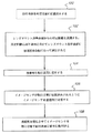
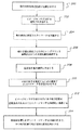
図5は、図3に例示された通り取付本体18にイメージセンサ26を位置決めするための方法のフローチャートである。ステップ100において、取付本体18が以下に詳述する方法によって所定位置に拘束(位置決め)される。レンズマウント基準表面22からの所定距離Dがステップ102で認識されて、取付位置を規定する。所定距離Dは取付表面24に向けて軸20に沿って測定され、ここで軸20はレンズマウント基準表面22にほぼ直角である。接着剤28が取付表面24に塗布される(ステップ104)。その後イメージセンサ26が、以下に詳述する手段によって、イメージセンサ26が接着剤と接触し、軸20に沿って所定距離Dにある取付位置に位置決めされるように、接着剤に貼着される(ステップ106)。接着剤が硬化させられ、イメージセンサ26は取付位置で取付表面24に確実に取付けられる(ステップ108)。そうしたものとして、接着剤28は、イメージセンサ26を所定距離Dで取付表面24にしっかりと取付けるために、イメージセンサ26を固定する。以下で詳述する通り、図5の方法は、レンズマウントアセンブリ10内にイメージセンサ26を接着するために実施され得るか、または代替的に、参照基準点に対して位置決めされた取付本体18にイメージセンサ26が接着された後、ミラーボックスアセンブリ19が取付本体18に取付けられるかもしれない。
FIG. 5 is a flowchart of a method for positioning the
イメージセンサをさらに保護するために、接着剤の硬化およびワイヤボンディングのステップに続き、透明カバーがイメージセンサ26に施用される。
A transparent cover is applied to the
実施の形態1
図5の方法は、ミラーボックスアセンブリ19が取付本体18に取付けられる前にイメージセンサ26が取付本体18に直接取付けられて、実施され得る。すなわち、ミラーボックスアセンブリ19は、イメージセンサ26が取付本体18に接着された後に取付本体18に取付けられる。イメージセンサ26は、レンズマウント12に向けられた取付本体18の側に配置された取付表面24に貼着されることになる。図6〜9を参照すれば、取付本体18は、所定位置を付与するために取付固定具30に拘束されている。固定具30は図6においてアウアー(Auer)ボートとして図示されているが、当業者は他の取付固定具が使用できることを認めるはずである。上述の通り、取付本体18の一例はカメラのリヤボディである。従って、図6〜9において、例示のためだけに、取付本体18はカメラのリヤボディとして図示されている。取付本体18は、ピン/スロットまたは左右x,y基準点輪郭特徴によって位置決めされ得る。
Embodiment 1
The method of FIG. 5 can be performed with the
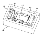
取付本体18は、当業者には周知のいくつかの方法によって取付固定具30内に位置決めされ得る。例えば、取付本体18は、ほぼ平面の固定具表面34によって支持されている、拘束された取付本体表面32として図6に図示された、取付表面24の反対の側面にほぼ平面の表面を備え得る。代替的に、固定具30は、取付本体18を位置決めするために取付本体18の特定の輪郭特徴と嵌合する輪郭特徴を備えることもできる。その後、固定具30または取付本体18のどちらか一方の輪郭特徴は、イメージセンサ26を、後にミラーボックスアセンブリ19を位置づけるための参照x,y,z基準面として使用される。すなわち、参照基準(datum)位置36a〜36cは、イメージセンサ26を所定距離Dに位置づけるために使用される。図7は、3つの参照基準位置36a〜36cを図示している。固定具30内での取付本体18のこの位置決めは、取付本体18の正確な拘束を付与する。
The mounting
取付本体18が固定具30内に位置決めされた状態で、その後、所定量の接着剤28が取付表面24に塗布される。イメージセンサ26はその後、取付表面24への取付けのために適位置に置かれる。イメージセンサ26は、以下に限らないが、手作業、ピックアンドプレイス機構などを含む、当業者に周知の手段によって適位置に置かれ得る。
With the mounting
そうしたピックアンドプレイス機構は、固定具30の近傍の場所からイメージセンサ26を「摘み取り」、イメージセンサ26を取付位置に「置く」ことができる。ピックアンドプレイス機構は、参照基準位置を突き止めるかまたは、識別子(fiducial)認識を可能にするためのビジョンイネーブルド装置(vision-enabled device)を備え得る。適格なビジョンイネーブルド装置の実例は、CCDカメラまたは類似物である。ビジョンイネーブルド装置はピックアンドプレイス機構を強化することができるが、ビジョンイネーブルド装置はピックアンドプレイス機構と分離できることが認められよう。
Such a pick and place mechanism can “pick” the
取付本体18または固定具30のどちらか一方からの参照基準位置が、イメージセンサ26の適正な位置決めのために決定される。例えば、図8を参照すれば、ピックアンドプレイス機構38が取付本体18の参照基準位置36a、36b、36cを突き止め得る。イメージセンサ26は接着剤28に取付けられ、その後、接着剤28は硬化させられる。硬化した後、ミラーボックスアセンブリ19およびシャッタ17(図示せず)が、図9に例示する通り、当業者には周知の手段によって取付本体18に取付けでき、それによってイメージセンサ26は基準表面22から所定距離Dに配置される。
A reference position from either the mounting
実施の形態2
第2の実施形態において、図5の方法は、参照基準点が基準表面22から参照されて、実施される。図10〜14を参照すれば、取付本体18が所定位置を与えるために固定具30において拘束される。やはり固定具30は図10〜14においてアウアーボートとして図示されているが、当業者は他の取付固定具が使用できることを認めるはずである。上述と同様、取付本体18の一例はカメラボディである。従って、図10〜14において、例示のためだけに、取付本体18はカメラボディとして図示される。固定具30内に位置決めされると、接着剤28が取付表面24に塗布される。
Embodiment 2
In a second embodiment, the method of FIG. 5 is performed with reference reference points referenced from the
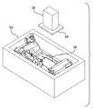
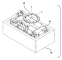
ここで図11を参照すれば、ピックアンドプレイス機構または類似物が、基準表面22の位置と一致する空間の参照基準x,y,zを突き止める(基準表面22は、基準点がこの表面から参照されることを例示するために各図に図示されている)。その後、ピックアンドプレイス機構38が使用されて取付表面24に配置された接着剤にイメージセンサ26を適正に貼着し、それによってイメージセンサ26は基準表面22から所定距離Dに配置される。硬化したら、取付本体18は固定具30から取り出され(図13)、その結果、ミラーボックスアセンブリ19およびシャッタ17(図示せず)が取付本体18に組み立てられ得る(図14)。
Referring now to FIG. 11, a pick-and-place mechanism or the like locates a reference x, y, z in a space that coincides with the location of the reference surface 22 (the reference surface is referenced from this surface by a reference point). Is shown in each figure to illustrate what is done). Thereafter, a pick and
実施の形態3
第3の実施形態において、図5の方法は、基準表面22が取付本体18に固定されている基準表面22から参照基準が参照されて、実施される。すなわち、イメージセンサ26がレンズマウント12およびレンズマウントサポート16の開口より小さいので、イメージセンサ26はミラーボックスアセンブリ19が取付本体18に取付けられる時に取付本体18に取付けることができる。
Embodiment 3
In a third embodiment, the method of FIG. 5 is performed with reference to a reference reference from the
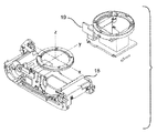
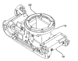
図15〜19を参照すれば、ミラーボックスアセンブリ19が取付本体18に取付けられた状態で、取付本体18は、所定位置を与えるために固定具30において拘束される。やはり固定具30は図15〜19においてアウアーボートとして図示されているが、当業者は他の取付固定具が使用できることを認めるはずである。上述と同様、取付本体18の一例はカメラボディである。従って、図15〜19において、例示のためだけに、取付本体18はカメラボディとして図示される。固定具30内に位置決めされると(図16および17)、接着剤28が取付表面24に塗布される。
Referring to FIGS. 15-19, with the
ここで図17を参照すれば、ピックアンドプレイス機構38または類似物が基準表面22を突き止めて、基準表面22における基準点x,y,zを決定する。その後、ピックアンドプレイス機構38が使用されて取付表面24に配置された接着剤にイメージセンサ26を適正に貼着し、それによってイメージセンサ26は基準表面22から所定距離Dに配置される(図18)。硬化したら、取付本体18は固定具30から取り出される(図19)。
Referring now to FIG. 17, a pick and
好ましい実施の形態
周知の通り、要素を正確に位置決めすることは、要素を空間座標の集合に正確に位置づけるために必要な最小数の力を指定することを伴う。図20に図示されているように、イメージセンサ26の装着には6自由度が存在する。これらの自由度は、x,y,z,θx,θyおよびθzである。θx,θyおよびzの自由度は、イメージセンサ26を所定の取付位置に取付けることによって制御される。xおよびyの制御は、レンズマウント12の中心から参照することによって得られる。θzの制御は、イメージセンサ26に識別子を使用し、識別子を取付表面に配置されたロケータと位置合わせすることによって得ることができる。このようにして、本発明は、光学式ビジョンシステムで強化されたピックアンドプレイス機械を使用する、自動化された精確な位置合わせ方法を提供する。
Preferred Embodiments As is well known, accurately positioning an element involves specifying the minimum number of forces required to accurately position the element in a set of spatial coordinates. As shown in FIG. 20, there are six degrees of freedom in mounting the
図21は、識別子およびロケータが使用される、本発明に従ってイメージセンサをレンズマウントアセンブリに位置決めする第2の方法の流れ図を示す。 FIG. 21 shows a flowchart of a second method for positioning an image sensor on a lens mount assembly according to the present invention, where an identifier and a locator are used.
ステップ200で、取付本体18が所定位置に拘束される。前述と同様、取付本体18の拘束は、例えば、固定具に対して取付本体18を正確に位置決めするためにレンズマウントアセンブリを固定具30に位置決めすることによって実現できる。識別子がイメージセンサ26で認識される(ステップ202)。さらに、取付表面24に配置されたロケータが認識される(ステップ204)。
At
レンズマウント12の中心から参照されるレンズマウント基準表面22からの所定距離Dがステップ206で認識されて、取付位置を規定し、正確なx,y,z位置を得る。接着剤28が取付表面24に塗布される(ステップ208)。識別子およびロケータが、平面の向きを規定するために位置合わせされる(ステップ210)。平面の向きは、イメージセンサ26の装着のためのx,y平面を規定することになる。イメージセンサ26が接着剤と接触し平面の向きにあり、軸20に沿って所定距離Dにある取付位置に位置決めされるように、イメージセンサ26が接着剤28に貼着される(ステップ212)。接着剤が硬化すると、イメージセンサ26は取付位置で取付表面24に確実に取付けられる(ステップ214)。硬化したら、残りのイメージセンサパッケージ/アセンブリがワイヤボンディングおよび機能試験を経て完成される。図22は、ワイヤボンディングされたイメージセンサ26の部分投影図を示す。
A predetermined distance D from the lens mount
図23は、イメージセンサ26に配置された識別子40を例示している。例示の通り、識別子40はクロスハッチとして図示されているが、当業者は、例えば線、点、星印または三角形などの他のマークが使用され得ることを認めるはずである。同様に、ロケータ42が取付支持18に図示されている。例示の通り、ロケータ42は星印として図示されているが、当業者は、例えば線、点、クロスハッチまたは三角形などの他のマークが使用され得ることを認めるはずである。
FIG. 23 illustrates an
識別子40およびロケータ42は、ステップ210において平面の向きを規定するために位置合わせされる。図23で座標系によって図示されている通り、識別子40とロケータ42との位置合わせは、取付表面24に対してイメージセンサ26を定位させるための平面を規定する。従って、この平面の向きは、取付表面24に対するイメージセンサ26の装着のためのx,y平面を規定する。
The
固定具30は、第1、第2および第3の実施形態に関して上述した通り、識別子40およびロケータ42の適正な位置合わせのために取付本体18を位置決めするように構成され得る。そうしたものとして、イメージセンサ26を貼着する手段/方法は、基準表面22から参照し、イメージセンサ26を装着して、精確なx,y,z位置を与えることができるであろう。
The
接着剤28が適切に硬化したら、光学システムのアセンブリは完成させることができる。例えば、イメージセンサ26を汚染から保護するためにイメージセンサ26上にガラスカバーを装着することが望ましいかもしれない。例えばピックアンドプレイス機構、光学式装着装置または類似物といった当業者に周知の方法が、ガラスカバーを装着するために使用され得る。
Once the adhesive 28 is properly cured, the assembly of the optical system can be completed. For example, it may be desirable to mount a glass cover over
従って、レンズ取付アセンブリ内でのイメージセンサの位置合わせおよびキャリブレーションは、イメージセンサを位置決めするために使用された手段/方法によるイメージセンサの装着によって実現される。 Thus, alignment and calibration of the image sensor within the lens mounting assembly is achieved by mounting the image sensor by the means / method used to position the image sensor.
所定の装着仕様が、イメージセンサの精確な装着を保証するために好適に規定される。例えば、最大スキュー角度が、焦点、傾倒、およびx/y寸法の公差と同様に規定されるであろう。本発明のイメージセンサ位置決めシステムおよび方法を使用することによって、イメージセンサは、±0.001インチの焦点および傾倒(Z+θx+θy)、2°の最大スキュー(θz)および、±0.003インチのxおよびyの範囲内の仕様範囲内で位置決めされている。 Predetermined mounting specifications are preferably defined to ensure accurate mounting of the image sensor. For example, the maximum skew angle will be defined as well as the focus, tilt, and x / y dimension tolerances. By using the image sensor positioning system and method of the present invention, the image sensor has a focus and tilt of ± 0.001 inches (Z + θx + θy), a maximum skew of 2 ° (θz), and x and ± 0.003 inches. It is positioned within the specification range of y.
本発明の方法は、レンズマウントアセンブリに対するイメージセンサの精確な装着を与えるために、正確な拘束モデリングを使用する。取付本体に対して直接のイメージセンサの装着は、公差スタックアップ(tolerance stackup)を排除/低減し、それによって、製造原価および製造時間を減少し、保守容易性を助成する。そうしたものとして、レンズマウントアセンブリ10は、アクティブアラインメント技法または機械加工後プロセスを要さずに焦点合わせされる。本発明の方法は、種々のレンズマウントアセンブリおよびイメージセンサにより使用できる。
The method of the present invention uses accurate constraint modeling to provide accurate mounting of the image sensor to the lens mount assembly. Mounting the image sensor directly on the mounting body eliminates / reduces tolerance stackup, thereby reducing manufacturing costs and time, and promoting maintainability. As such,
実施の形態4
第4の実施形態において、イメージセンサ26はプレートに取付けられ、そのプレートが取付本体18に位置決めされる。すなわち、イメージセンサ26は(拘束モデリングを用いて)プレートに精密装着され、プレートはカメラボディ内に直接取付けられ得る。イメージセンサをプレートに直接位置決めすることは、公差スタックアップを排除し、それによって、いかなる他のアクティブアラインメントプロセスまたは技法を要さずにイメージセンサをカメラに装着可能にする。
Embodiment 4
In the fourth embodiment, the
図24〜26を参照すれば、ディジタルカメラにおける使用のためにイメージセンサパッケージ/アセンブリ48を作成する方法が図示されている。プレート50が容易される(ステップ300)。プレート50は、図24(b)および24(c)に最善に図示された通り、イメージセンサ26を受けるためにほぼ平面の表面を有する。プレート50はまた、取付本体18の装着輪郭特徴と嵌合するための輪郭特徴も備える。これらの輪郭特徴は、図24aにおいて取付穴52として図示されている。(4つの輪郭特徴、すなわち取付穴52が図示されているが、3つの輪郭特徴も使用できることに留意されたい。一部の用途では、5つの輪郭特徴が確定され得る。)プレート50は、プレート50を所定位置に位置決めするために固定具30に位置決めされる(ステップ302)。上述の実施形態に関してと同様、固定具30は、プレート50をx,yの所定位置に位置決めするためのピン/スロットを備え得る。接着剤28が取付表面に塗布される(ステップ304)。上述の実施形態3に関してと同様、識別子がイメージセンサ26において認識される(ステップ306)。同様に、プレート50の取付表面に配置されたロケータが認識される(ステップ308)。これらの識別子およびロケータは、ピックアンドプレイス機構または類似物によって突き止められ、平面の向きを規定するために位置合わせされる(ステップ312)。ピックアンドプレイス機構38がイメージセンサ26を取付表面に移送する。好ましくは、ピックアンドプレイス機構は、イメージセンサ26を所定の仕様で装着するために輪郭特徴52によってプレート50と接触する(ステップ314)。すなわち、イメージセンサ26は、イメージセンサが平面の向きにあり、取付位置に位置決めされるように接着剤28に貼着される。その後、接着剤は硬化させられて、イメージセンサを平面の向きで、かつ取付位置において取付表面に確実に取付ける(ステップ316)。その後、セラミックフレーム54、光学カバーガラス/フィルタ56および、ピン58との電気的接続を付与する接合パッド(図示せず)へのワイヤボンディングを含み、イメージセンサアセンブリが完成される。組み立てられたら、イメージセンサアセンブリ48は、図25に最善に図示される通り、同じx,y,z参照位置を用いてカメラボディ60内に位置決めされる。
Referring to FIGS. 24-26, a method of making an image sensor package /
D 所定距離、10 レンズマウントアセンブリ、12 レンズマウント、14 レンズ、16 レンズマウントサポート、17 シャッタ、18 取付本体、19 ミラーボックスアセンブリ、20 軸;光軸、22 レンズマウント基準表面、24 取付表面、25 イメージセンサの表面、26 イメージセンサ、28 接着剤、30 固定具、31 イメージセンサの側端、32 取付本体表面、34 固定具表面、36 参照基準位置、38 ピックアンドプレイス機構、40 識別子、42 ロケータ、48 イメージセンサパッケージ/アセンブリ、50 プレート、52 輪郭特徴/取付穴、54 フレーム、56 カバーガラス/フィルタ、58 ピン、60 カメラボディ。
D predetermined distance, 10 lens mount assembly, 12 lens mount, 14 lens, 16 lens mount support, 17 shutter, 18 mounting body, 19 mirror box assembly, 20 axes; optical axis, 22 lens mount reference surface, 24 mounting surface, 25 Image sensor surface, 26 Image sensor, 28 Adhesive, 30 Fixture, 31 Image sensor side edge, 32 Mounting body surface, 34 Fixture surface, 36 Reference position, 38 Pick and place mechanism, 40 Identifier, 42
Claims (3)
取付本体を所定位置に位置決めする工程と、
取付位置を規定するために、基準表面から、取付表面に向けて基準表面にほぼ直角な軸に沿って測定された所定距離を認識する工程と、
接着剤を取付表面に塗布する工程と、
イメージセンサが取付位置に位置決めされるようにイメージセンサを接着剤に貼着する工程と、
接着剤を硬化させてイメージセンサを取付位置で取付表面に確実に取付ける工程と、
を含む方法。 A method of positioning an image sensor with respect to a mounting body having a substantially planar mounting surface disposed substantially parallel to a lens mount reference surface to which a lens is mounted,
Positioning the mounting body at a predetermined position;
Recognizing a predetermined distance measured along an axis substantially perpendicular to the reference surface from the reference surface toward the mounting surface to define the mounting position;
Applying an adhesive to the mounting surface;
Affixing the image sensor to an adhesive so that the image sensor is positioned at the mounting position,
Curing the adhesive and securely mounting the image sensor on the mounting surface at the mounting position;
A method that includes
取付本体を所定位置に位置決めする工程と、
イメージセンサにおける識別子を認識する工程と、
取付表面に配置されたロケータを認識する工程と、
取付位置を規定するために、レンズマウント基準表面から、取付表面に向けてレンズマウント基準表面にほぼ直角な軸に沿って測定された所定距離を認識する工程と、
接着剤を取付表面に塗布する工程と、
平面の向きを規定するために識別子およびロケータを位置合わせする工程と、
イメージセンサが平面の向きにあり取付位置に位置決めされるようにイメージセンサを接着剤に貼着する工程と、
接着剤を硬化させてイメージセンサを平面の向きで、かつ取付位置で取付表面に確実に取付ける工程と、
を含む方法。 A method of positioning an image sensor with respect to a mounting body having a substantially planar mounting surface disposed substantially parallel to a lens mount reference surface to which a lens is mounted,
Positioning the mounting body at a predetermined position;
Recognizing an identifier in the image sensor;
Recognizing a locator located on the mounting surface;
Recognizing a predetermined distance measured along an axis substantially perpendicular to the lens mount reference surface from the lens mount reference surface toward the mounting surface to define the mounting position;
Applying an adhesive to the mounting surface;
Aligning the identifier and locator to define a plane orientation;
Affixing the image sensor to the adhesive so that the image sensor is oriented in a plane and positioned at the mounting position,
Curing the adhesive to securely attach the image sensor to the mounting surface in the plane direction and at the mounting position;
A method that includes
ほぼ平面の取付表面を有するプレートを用意する工程と、
プレートを所定位置で固定具に位置決めする工程と、
接着剤を取付表面に塗布する工程と、
イメージセンサにおける識別子を認識する工程と、
取付表面に配置されたロケータを認識する工程と、
取付位置を規定するために、基準表面から取付表面に向けて基準表面にほぼ直角な軸に沿って測定された所定距離を認識する工程と、
平面の向きを規定するために識別子およびロケータを位置合わせする工程と、
イメージセンサが平面の向きにあり取付位置に位置決めされるようにイメージセンサを接着剤に貼着する工程と、
接着剤を硬化させてイメージセンサを平面の向きで、かつ取付位置で取付表面に確実に取付ける工程と、を含む方法。 A method of making an image sensor assembly, comprising:
Providing a plate having a substantially planar mounting surface;
Positioning the plate on the fixture at a predetermined position;
Applying an adhesive to the mounting surface;
Recognizing an identifier in the image sensor;
Recognizing a locator located on the mounting surface;
Recognizing a predetermined distance measured along an axis substantially perpendicular to the reference surface from the reference surface to the mounting surface to define the mounting position;
Aligning the identifier and locator to define a plane orientation;
Affixing the image sensor to the adhesive so that the image sensor is oriented in a plane and positioned at the mounting position,
Curing the adhesive to securely attach the image sensor to the mounting surface in the planar orientation and at the mounting location.
Applications Claiming Priority (1)
| Application Number | Priority Date | Filing Date | Title |
|---|---|---|---|
| US10/324,318 US20040121503A1 (en) | 2002-12-19 | 2002-12-19 | Image sensor positioning system and method |
Publications (1)
| Publication Number | Publication Date |
|---|---|
| JP2004201328A true JP2004201328A (en) | 2004-07-15 |
Family
ID=32393063
Family Applications (1)
| Application Number | Title | Priority Date | Filing Date |
|---|---|---|---|
| JP2003421708A Pending JP2004201328A (en) | 2002-12-19 | 2003-12-18 | Image sensor positioning system and method |
Country Status (3)
| Country | Link |
|---|---|
| US (1) | US20040121503A1 (en) |
| EP (1) | EP1432240A1 (en) |
| JP (1) | JP2004201328A (en) |
Families Citing this family (8)
| Publication number | Priority date | Publication date | Assignee | Title |
|---|---|---|---|---|
| TWI221727B (en) * | 2003-07-07 | 2004-10-01 | Avision Inc | Method for adjusting a scanning module |
| JP4391838B2 (en) * | 2004-01-27 | 2009-12-24 | Hoya株式会社 | Digital camera |
| EP1734743A3 (en) * | 2005-06-16 | 2011-08-31 | Basler Aktiengesellschaft | Carrier for sensor boards |
| DE102005027892A1 (en) * | 2005-06-16 | 2006-12-28 | Basler Ag | Support carrier for electronic light sensitive sensors of camera, has mechanical coding corresponding to mechanical coding on circuit board |
| US20090121300A1 (en) * | 2007-11-14 | 2009-05-14 | Micron Technology, Inc. | Microelectronic imager packages and associated methods of packaging |
| US9104039B2 (en) * | 2012-05-08 | 2015-08-11 | Avago Technologies General Ip (Singapore) Pte. Ltd. | Methods and systems for performing vision-aided passive alignment during the assembly of an optical communications module |
| US11838613B2 (en) | 2017-04-27 | 2023-12-05 | Allied Vision Technologies Gmbh | Method for capturing data |
| CN112153286B (en) * | 2020-09-24 | 2021-12-03 | 广州极飞科技股份有限公司 | AA (advanced) processing method, AA processing equipment and system for image sensor |
Family Cites Families (9)
| Publication number | Priority date | Publication date | Assignee | Title |
|---|---|---|---|---|
| JPS58140156A (en) * | 1982-02-16 | 1983-08-19 | Canon Inc | Solid-state image pickup device |
| US5861654A (en) * | 1995-11-28 | 1999-01-19 | Eastman Kodak Company | Image sensor assembly |
| US6011294A (en) * | 1996-04-08 | 2000-01-04 | Eastman Kodak Company | Low cost CCD packaging |
| US5757485A (en) * | 1996-11-22 | 1998-05-26 | Eastman Kodak Company | Digital camera image sensor positioning method including a non-coherent interferometer |
| US6147389A (en) * | 1999-06-04 | 2000-11-14 | Silicon Film Technologies, Inc. | Image sensor package with image plane reference |
| US6389687B1 (en) * | 1999-12-08 | 2002-05-21 | Amkor Technology, Inc. | Method of fabricating image sensor packages in an array |
| WO2001044850A2 (en) * | 1999-12-16 | 2001-06-21 | Iridian Technologies, Inc. | Lens alignment system for solid state imager |
| US6956615B2 (en) * | 2000-01-28 | 2005-10-18 | Pentax Corporation | Structure for mounting a solid-state imaging device |
| JP2002328292A (en) * | 2001-04-27 | 2002-11-15 | Toshiba Corp | Imaging unit manufacturing method and imaging unit |
-
2002
- 2002-12-19 US US10/324,318 patent/US20040121503A1/en not_active Abandoned
-
2003
- 2003-12-08 EP EP03078835A patent/EP1432240A1/en not_active Withdrawn
- 2003-12-18 JP JP2003421708A patent/JP2004201328A/en active Pending
Also Published As
| Publication number | Publication date |
|---|---|
| EP1432240A1 (en) | 2004-06-23 |
| US20040121503A1 (en) | 2004-06-24 |
Similar Documents
| Publication | Publication Date | Title |
|---|---|---|
| US5861654A (en) | Image sensor assembly | |
| US5998878A (en) | Image sensor assembly and packaging method | |
| US7088397B1 (en) | Image sensor packaging with imaging optics | |
| KR100428278B1 (en) | Micro camera and manufacturing thereof | |
| US8711277B2 (en) | Method for assembling a camera module, and camera module | |
| EP1943833B1 (en) | Wafer based camera module and method of manufacture | |
| KR20180132684A (en) | Camera module, its photosensitive part and method of manufacturing the same | |
| US7587803B2 (en) | Method for assembling a camera module | |
| CN100507699C (en) | Mounting board for solid state image device and method for connecting solid state image device on mounting board | |
| CN101124813A (en) | Integrated lens and chip assembly for digital camera | |
| JP5385336B2 (en) | Optoelectronic alignment system and method | |
| EP1659781A1 (en) | Image pickup module and manufacturing method of image pickup module | |
| KR20040084989A (en) | Module for optical device, and manufacturing method therefor | |
| US20190219897A1 (en) | Optically Aligned Camera Module Assembly Using Soldering | |
| JP2004201328A (en) | Image sensor positioning system and method | |
| CN107404608A (en) | Camara module for vehicle | |
| JP2000241696A (en) | How to hold and mount the optical sensor package | |
| JP3776522B2 (en) | Ranging light receiving device and manufacturing method thereof | |
| US5764366A (en) | Method and apparatus for alignment and bonding | |
| JP3948551B2 (en) | Mounting method and mounting apparatus | |
| CN109104553B (en) | Camera module | |
| JPS60212070A (en) | Solid-state image pickup device | |
| EP0886322A2 (en) | Packaging of imaging devices | |
| JP3682416B2 (en) | Method for aligning optical element and lens assembly | |
| CN117192716A (en) | Method of assembling optical device and optical device assembled according to the method |