JP2004201411A - Power supply control device and control method thereof - Google Patents
Power supply control device and control method thereof Download PDFInfo
- Publication number
- JP2004201411A JP2004201411A JP2002367054A JP2002367054A JP2004201411A JP 2004201411 A JP2004201411 A JP 2004201411A JP 2002367054 A JP2002367054 A JP 2002367054A JP 2002367054 A JP2002367054 A JP 2002367054A JP 2004201411 A JP2004201411 A JP 2004201411A
- Authority
- JP
- Japan
- Prior art keywords
- storage battery
- engine
- generator
- frequency
- power supply
- Prior art date
- Legal status (The legal status is an assumption and is not a legal conclusion. Google has not performed a legal analysis and makes no representation as to the accuracy of the status listed.)
- Granted
Links
Images
Classifications
-
- Y—GENERAL TAGGING OF NEW TECHNOLOGICAL DEVELOPMENTS; GENERAL TAGGING OF CROSS-SECTIONAL TECHNOLOGIES SPANNING OVER SEVERAL SECTIONS OF THE IPC; TECHNICAL SUBJECTS COVERED BY FORMER USPC CROSS-REFERENCE ART COLLECTIONS [XRACs] AND DIGESTS
- Y02—TECHNOLOGIES OR APPLICATIONS FOR MITIGATION OR ADAPTATION AGAINST CLIMATE CHANGE
- Y02E—REDUCTION OF GREENHOUSE GAS [GHG] EMISSIONS, RELATED TO ENERGY GENERATION, TRANSMISSION OR DISTRIBUTION
- Y02E60/00—Enabling technologies; Technologies with a potential or indirect contribution to GHG emissions mitigation
- Y02E60/10—Energy storage using batteries
-
- Y—GENERAL TAGGING OF NEW TECHNOLOGICAL DEVELOPMENTS; GENERAL TAGGING OF CROSS-SECTIONAL TECHNOLOGIES SPANNING OVER SEVERAL SECTIONS OF THE IPC; TECHNICAL SUBJECTS COVERED BY FORMER USPC CROSS-REFERENCE ART COLLECTIONS [XRACs] AND DIGESTS
- Y02—TECHNOLOGIES OR APPLICATIONS FOR MITIGATION OR ADAPTATION AGAINST CLIMATE CHANGE
- Y02T—CLIMATE CHANGE MITIGATION TECHNOLOGIES RELATED TO TRANSPORTATION
- Y02T10/00—Road transport of goods or passengers
- Y02T10/60—Other road transportation technologies with climate change mitigation effect
- Y02T10/62—Hybrid vehicles
Landscapes
- Control Of Vehicle Engines Or Engines For Specific Uses (AREA)
- Control Of Charge By Means Of Generators (AREA)
- Secondary Cells (AREA)
- Hybrid Electric Vehicles (AREA)
- Output Control And Ontrol Of Special Type Engine (AREA)
Abstract
【課題】本発明は、回生エネルギーを蓄電池に回収して車の燃費を向上し排気ガスを減少させ、且つ渋滞した市街地での走行等において蓄電池の寿命が縮むことを防止する電源制御装置及びその制御方法を提供する。
【解決手段】本発明の電源制御装置は、エンジンと、前記エンジンによって駆動される発電機と、前記発電機によって充電される蓄電池と、前記蓄電池の充電状態が所定の範囲内になるように前記蓄電池の充放電を制御する蓄電池充放電制御部と、を有し、車に搭載されており、前記蓄電池充放電制御部は、前記エンジン又は前記車が停止した状態が発生する頻度を検出し、前記頻度が所定の閾値以上である場合における前記所定の範囲の上限値を、前記頻度が前記所定の閾値未満である場合における前記上限値より低く設定することを特徴とする。
【選択図】 図1The present invention relates to a power supply control device that recovers regenerative energy in a storage battery, improves fuel efficiency of the vehicle, reduces exhaust gas, and prevents the life of the storage battery from being shortened when traveling in a congested city area and the like. A control method is provided.
A power supply control device according to the present invention includes an engine, a generator driven by the engine, a storage battery charged by the generator, and a storage state of the storage battery within a predetermined range. A storage battery charge / discharge control unit that controls the charge / discharge of the storage battery, and is mounted on a vehicle, wherein the storage battery charge / discharge control unit detects a frequency at which the state in which the engine or the vehicle is stopped occurs, An upper limit of the predetermined range when the frequency is equal to or higher than a predetermined threshold is set lower than the upper limit when the frequency is lower than the predetermined threshold.
[Selection diagram] Fig. 1
Description
【0001】
【発明の属する技術分野】
本発明は、電源制御装置及びその制御方法に関する。
【0002】
【従来の技術】
近年、大気汚染への関心の高まりから、不要な排気ガスの排出を抑えるために、車が駐停車した時、短時間で又は直ちに自動的にエンジンを停止し(アイドリング状態を停止し)、燃費を改善するアイドルストップ機能を有する車(以下、「アイドルストップ車」と言う。)が開発されている。アイドルストップ車は、アイドルストップ機能を有さない車と比較して、エンジンを停止状態から再起動する頻度(蓄電池からエンジン始動用のセルモータへ電力供給する頻度)がはるかに高い。また、アイドルストップ中には蓄電池から、車両の制御系統や、ライト、オーディオ等に電力を供給する。このようなアイドルストップ車の蓄電池には、従来より使用されている安価な液式鉛蓄電池が検討されている。
【0003】
液式鉛蓄電池は、アイドルストップによる放電でSOC(充電状態。State ofCharge。放電容量を意味する。)が大きく低下し、充電不足の状態が続くと、電解液の成層化が生じ、サルフェーションが発生するので寿命が急激に短くなる。このため従来の、安価な液式鉛蓄電池を使用する車にアイドルストップ機能を搭載する場合、電池の劣化を防止する電源制御が重要である。アイドルストップを行わない従来の車では、常時SOCを100%近くに保つように充電電圧を高く設定し、充電不足にならないよう制御されている。
【0004】
特許第3211699号公報に、従来例1の動力出力装置が開示されている。従来例1の動力出力装置は、車両の走行条件及び予測される走行条件に応じてバッテリのSOCの目標値を設定し、エンジンと発電機とを制御する。走行条件は、車両の速度、加速度、高度、ナビゲーションシステムに記憶されている地図情報のうち少なくともひとつの情報を使用して定量化する。
【0005】
特開平11−008909号公報に従来例2のハイブリッド電気自動車の発電制御装置が開示されている。従来例2のハイブリッド電気自動車の発電制御装置は、車両が登坂する時に、降坂完了までに得られる積算回生エネルギーを予測する。そして、その回生エネルギーで電池を充電した場合に予測される充電量の分だけ、電池のSOCの目標値を引き下げる。従って、降坂時の回生エネルギーを、無駄なく電池の充電という形で受け入れることができる。
【0006】
特開2001−268708号公報に、従来例3のハイブリッド車両の制御装置が開示されている。従来例3のハイブリッド車両の制御装置は、バッテリの劣化度に応じて充電レベルの目標値を変更する。更に、定常運転時には減速運転時よりも充電レベルの目標値を低く設定する。
【0007】
【特許文献1】
特許第3211699号公報
【特許文献2】
特開平11−008909号公報
【特許文献3】
特開2001−268708号公報
【0008】
【発明が解決しようとする課題】
アイドルストップ車は、停止中及び停止後のエンジン始動やスタート時に蓄電池を放電する故に、蓄電池のSOCを減少させる。蓄電池のSOCが低下した場合、アイドルストップ車が暫くの間走り続ければ蓄電池は充電され、そのSOCは再び高くなる。しかし、渋滞する市街地等を走行するアイドルストップ車は、僅かの距離を走行しては停止することを繰り返す場合がある。この場合、蓄電池はほとんど充電されないまま放電を繰り返すことになる。このような場合、蓄電池のSOCがアイドルストップ車のスタートに必要な最低限度未満になって、アイドルストップ車が動けなくなる恐れがあった。このため、SOCの下限値を設定し、この下限値になるとアイドルストップをキャンセルするような制御も提案されているが、アイドルストップの回数が減少するので燃費改善の効果が少なくなる。また、SOCが低い状態のまま使用されるので、液式鉛蓄電池では特に、成層化によるサルフェーションが生じ、短寿命になる恐れがあった。一方、高速道路や信号機の少ない走行では、アイドルストップの頻度が少ないので蓄電池の放電が少なく充電時間が長くなる。従って、従来の充電制御のように一定の充電電圧で充電し、SOCを100%近くに制御する方法では過充電となり、燃費改善の効果は期待できない。また、SOCが100%近くに制御されるので回生の充電も受け入れることができない。
【0009】
従来例1〜3の動力出力装置等は、自動車の走行条件、バッテリの状態に応じて蓄電池の充放電を制御している。しかし、従来例1〜3の電源装置等は、渋滞した市街地での走行等において蓄電池が短寿命になる恐れがあるという上記の問題を解決するものではなかった。
【0010】
本発明は上記従来の問題点を解決するもので、アイドルストップの頻度が少ない、高速道路や信号機の少ない走行でも回生エネルギーを蓄電池に回収して車の燃費を向上し排気ガスを減少させ、且つ渋滞した市街地での走行等において蓄電池が短寿命になることを防止する電源制御装置及びその制御方法を提供する。
【0011】
【課題を解決するための手段】
上記課題を解決するため、本発明は以下の構成を有する。請求項1に記載の発明は、エンジンと、前記エンジンによって駆動される発電機と、前記発電機によって充電される蓄電池と、前記蓄電池の充電状態が所定の範囲内になるように前記蓄電池の充放電を制御する蓄電池充放電制御部と、を有し、車に搭載されており、前記蓄電池充放電制御部は、前記エンジン又は前記車が停止した状態が発生する頻度を検出し、前記頻度が所定の閾値以上である場合における前記所定の範囲の上限値を、前記頻度が前記所定の閾値未満である場合における前記上限値より低く設定することを特徴とする電源制御装置である。
【0012】
請求項2に記載の発明は、前記発電機は、前記エンジンを補助する電動機として動作することができ、前記蓄電池充放電制御部は、少なくとも前記エンジンが停止状態から動作状態に変化した時に前記蓄電池が放電して前記発電機を電動機として駆動し、前記エンジンが動作状態を継続した後は前記蓄電池が前記発電機によって充電されるように前記蓄電池の充放電を制御することを特徴とする請求項1に記載の電源制御装置である。
【0013】
請求項3に記載の発明は、前記蓄電池充放電制御部は、前記頻度が前記所定の閾値以上である場合における前記上限値を前記蓄電池の最大定格に設定し、前記頻度が前記所定の閾値未満である場合又は前記所定の閾値より低い値である他の閾値未満である場合における前記上限値を前記蓄電池が前記発電機からの回生エネルギーを充電可能な値に設定することを特徴とする請求項1又は請求項2に記載の電源制御装置である。
【0014】
請求項4に記載の発明は、前記蓄電池が鉛蓄電池であることを特徴とする請求項1又は請求項2に記載の電源制御装置である。
【0015】
請求項5に記載の発明は、エンジンと、前記エンジンによって駆動される発電機と、前記発電機によって充電される蓄電池とを有し、車に搭載された電源制御装置の制御方法であって、前記蓄電池の充電状態が所定の範囲内になるように前記蓄電池の充放電を制御する制御ステップと、前記エンジン又は前記車が停止した状態が発生する頻度を検出する検出ステップと、を有し、前記頻度が所定の閾値以上である場合における前記制御ステップの前記所定の範囲の上限値を、前記頻度が前記所定の閾値未満である場合における前記上限値より低く設定することを特徴とする電源制御装置の制御方法である。
【0016】
請求項6に記載の発明は、前記発電機は、前記エンジンを補助する電動機として動作することができ、少なくとも前記エンジンが停止状態から動作状態に変化した時に前記蓄電池が放電して前記発電機を電動機として駆動し、前記エンジンが動作状態を継続した後は前記蓄電池が前記発電機によって充電されるように前記蓄電池の充放電を制御することを特徴とする請求項5に記載の電源制御装置の制御方法である。
【0017】
請求項7に記載の発明は、前記頻度が前記所定の閾値以上である場合における前記上限値を前記蓄電池の最大定格に設定し、前記頻度が前記所定の閾値未満である場合又は前記所定の閾値より低い値である他の閾値未満である場合における前記上限値を前記蓄電池が前記発電機からの回生エネルギーを充電可能な値に設定することを特徴とする請求項5又は請求項6に記載の電源制御装置の制御方法である。
【0018】
本発明の発明者は、アイドルストップ車に搭載された蓄電池は、エンジン始動やスタート時に放電する故に、特に渋滞する市街地等で僅かの距離を走行しては停止することを繰り返す場合、蓄電池の放電量が、エンジン又は車の停止回数に比例することを発見した。エンジン又は車が停止した状態が発生する頻度が高ければ、蓄電池の充電量が放電量に追いつかない恐れがある。このような場合、蓄電池のSOCを高くするように制御することにより、蓄電池の寿命が短くなることを防止できる。一方、車が高速道路を走行する場合、エンジン又は車が停止した状態の発生頻度は低い。このような場合、蓄電池のSOCを低くするように制御することにより、回生エネルギーを確実に蓄電池に回収することができる。
鉛蓄電池を使用するアイドルストップ車においては、蓄電池をほとんど充電しないまま放電を繰り返すと、鉛蓄電池の寿命が縮む。
「エンジン又は車が停止した状態が発生する頻度」は、動作状態から停止状態に変化する頻度をカウントしても良く、停止状態から動作状態に変化する頻度をカウントしても良い。
【0019】
本発明は、回生エネルギーを蓄電池に回収して車の燃費を向上し排気ガスを減少させ、且つ渋滞した市街地での走行等において、蓄電池の過放電を防ぎ、鉛蓄電池等の蓄電池の寿命が短くなることを防止する電源制御装置及びその制御方法を実現できるという作用を有する。
【0020】
【発明の実施の形態】
以下本発明の実施をするための最良の形態を具体的に示した実施例について、図面とともに記載する。
【0021】
《実施例》
図1〜図3を用いて、本発明の実施例の電源制御装置及びその制御方法を説明する。実施例の電源制御装置は、アイドルストップ車に搭載されている。
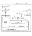
図2は、実施例の電源制御装置の構成を示すブロック図である。図2において、200はアイドルストップ車、201は発電機、202は負荷、203は12V、50Ahの液式鉛蓄電池、204は電流センサ、205は電流計測部、206は電圧計測部、210はエンジン、211は蓄電池充放電制御部である。蓄電池充放電制御部211は、SOC算出部207、アイドルストップ頻度算出部208、発電機制御部209を有する。
【0022】
アイドルストップ車200は、駐停車にアイドリング状態にすることなく自動的にエンジンを停止する又は短時間のアイドリングの後自動的にエンジンを停止する、アイドルストップ機能を有する。発電機201はアイドルストップ車200のエンジン210によって駆動されて発電を行う。発電された電力は負荷202及び液式鉛蓄電池203に供給される。負荷202は、具体的にはオーディオ装置、エアコン、ランプ等の電装品、エンジン始動用のセルモータである。液式鉛蓄電池203は走行中はほとんど常に、発電機201からの電力によって定電圧充電されている。アイドルストップ等によりエンジン210が停止している間は、液式鉛蓄電池203は負荷202(オーディオ装置、エアコン、ランプ等)に電力を供給するために放電する。エンジン210が始動する時、液式鉛蓄電池203が放電して発電機201を電動機として駆動し且つ負荷202(エンジン始動用のセルモータ)に電力を供給する。アイドルストップ車200の減速及びブレーキ時に、発電機201に回生電流(回生エネルギー)が発生する。液式鉛蓄電池203は、この回生電流によって充電される。
【0023】
電流センサ204は液式鉛蓄電池203に流れる電流を検出する。電流センサ204の出力は電流計測部205に入力され、更にSOC算出部207に電流値として入力される。電圧計測部206は液式鉛蓄電池203の電圧を測定し、測定した電圧値を発電機制御部209に出力する。
蓄電池充放電制御部211は、液式鉛蓄電池203のSOCが所定の範囲内になるように、液式鉛蓄電池203の充放電を制御する。SOC算出部207は、液式鉛蓄電池203の満充電時の電池容量に充放電電気量の積算値を加算することによりSOCを算出し、発電機制御部209に出力する。
【0024】
発電機制御部209は、発電機201の励磁電流を制御することにより、発電機201の出力電圧を制御する。
アイドルストップ頻度算出部208は、10分当たりのアイドルストップの発生回数(発生頻度)を算出し、発電機制御部209に出力する。
【0025】
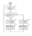
図1は、実施例の電源制御装置の制御方法を示すフローチャートである。ステップ101でアイドルストップ頻度算出部208は、10分当たりのアイドルストップの頻度を算出する。発電機制御部209は、10分当たりのアイドルストップの頻度が2回以上か否か判断する(ステップ102)。2回以上の場合はステップ103に進み、SOCの目標値(蓄電池の放電容量の制御範囲の上限値)を100%(満充電)に設定する。発電機制御部209は発電機201の出力電圧を15Vに設定し、SOCを100%に近づける充電を行う(ステップ105)。ステップ101に戻る。
【0026】
ステップ102で、10分当たりのアイドルストップの頻度が2回未満の場合はステップ104に進み、SOCの目標値を95%に設定する。発電機制御部209は発電機201の出力電圧を13Vに設定し、SOCを95%に近づける制御を行う(ステップ105)。ステップ101に戻る。
【0027】
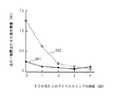
図3は、従来例と本発明の電源制御装置をそれぞれ有するアイドルストップ車において、10分当たりのアイドルストップの頻度と走行1時間当たりの過充電量との関係を示す図である。電圧が12V、電池容量が50Ahの液式鉛蓄電池をアイドルストップ車200及び従来の電源制御装置を有するアイドルストップ車にそれぞれ搭載し、10分当たりのアイドルストップの頻度を様々に変え、走行1時間当たりの過充電量を調べる実験を行った。アイドルストップ1回当たりの平均放電量は、電池容量の0.5%とした。実線301は、図1のフローチャートに示した方法で蓄電池の充放電制御を行う本発明の電源制御装置を有するアイドルストップ車の実験結果である。破線302は、常にSOCを100%に近づける定電圧充電(充電電圧は14V)を行う従来例の電源制御装置を有するアイドルストップ車の実験結果である。
【0028】
液式鉛蓄電池203は、完全充電せずに使用され続けると、サルフェーションが発生する。つまり、放電生成物である硫酸鉛が蓄積して充電できなくなり、性能低下を引き起こす。サルフェーションが発生すると、液式鉛蓄電池203の寿命は急速に短くなる。市街地での走行のようにアイドルストップの頻度が高い場合は、アイドルストップ中の液式鉛蓄電池203の放電量が多くなるとともに、充電時間が短くなるのでSOCが低下しやすい。本実施例によれば、このような場合には発電機201を制御し、充電電圧を高く設定するので、液式鉛蓄電池203を短時間で充電するとともにSOCを高く保てる。これにより、液式鉛蓄電池203の電解液の成層化を抑え、長寿命化を図ることができる。
【0029】
高速走行時のようにアイドルストップの頻度が低い場合には、液式鉛蓄電池203が充電不足になる恐れが少ないため、SOCの設定値を下げる(実施例においては95%)。鉛蓄電池203は常に満充電されていない状態である故に、ブレーキや減速による回生エネルギーを効率的に液式鉛蓄電池203に蓄積できる。実施例において、回生エネルギーが無駄なく液式鉛蓄電池203の充電に使用されていることが図3(発生した過充電量の大きさが無駄に消費された回生エネルギーの大きさを示す。)より分かる。図3の破線302に示すように、常にSOCを100%に近づける充電を行った場合は、回生エネルギーのロスが発生する。本発明により、過充電による電池の劣化や電解液の減少を防止でき、且つ燃費が向上する。
【0030】
ステップ102で用いる、10分当たりのアイドルストップ頻度の閾値は走行条件及び使用する蓄電池の種類によって変更して良い。実施例では、アイドルストップの頻度に応じてSOCの目標値を2段階に設定したが、3段階以上設定しても良く、連続的に変化する値(例えばアイドルストップの発生頻度をパラメータとし、SOCの目標値を導出する関数を使用する。)にしても良い。
実施例においては、エンジンが停止する頻度が高い場合にSOCの目標値を高くし、頻度が低い場合にSOCの目標値を低くした。これに代えて、車が停止した状態が発生する頻度が高い場合にSOCの目標値を高くし、頻度が低い場合にSOCの目標値を低くしても良い。
【0031】
【発明の効果】
本発明によれば、回生エネルギーを蓄電池に回収して車の燃費を向上し排気ガスを減少させ、且つ渋滞した市街地での走行等において、蓄電池の過放電を防ぎ、鉛蓄電池等の蓄電池の寿命が短くなることを防止する電源制御装置及びその制御方法を実現できるという有利な効果が得られる。
【図面の簡単な説明】
【図1】本発明の実施例の電源制御装置の制御方法を示すフローチャート
【図2】本発明の実施例の電源制御装置の構成を示すブロック図
【図3】従来例と本発明の電源制御装置をそれぞれ有するアイドルストップ車において、10分当たりのアイドルストップの頻度と走行1時間当たりの過充電量との関係を示す図
【符号の説明】
200 アイドルストップ車
201 発電機
202 負荷
203 液式鉛蓄電池
204 電流センサ
205 電流計測部
206 電圧計測部
207 SOC算出部
208 アイドルストップ頻度算出部
209 発電機制御部
210 エンジン
211 蓄電池充放電制御部[0001]
TECHNICAL FIELD OF THE INVENTION
The present invention relates to a power supply control device and a control method thereof.
[0002]
[Prior art]
In recent years, due to the increasing interest in air pollution, in order to suppress unnecessary emission of exhaust gas, when a car is parked and stopped, the engine is automatically stopped in a short time or immediately (stopping the idling state) to reduce fuel consumption. (Hereinafter referred to as "idle-stop vehicle") having an idle-stop function for improving the vehicle speed. The frequency of restarting the engine from the stopped state (frequency of supplying power from the storage battery to the cell motor for starting the engine) is much higher in the idle stop vehicle than in the vehicle having no idle stop function. During idle stop, the storage battery supplies power to the vehicle control system, lights, audio, and the like. Inexpensive liquid lead-acid batteries that have been used in the past are being studied for such idle-stop storage batteries.
[0003]
In a liquid lead-acid battery, the SOC (State of Charge; meaning discharge capacity) is greatly reduced by discharging by idle stop, and if the state of insufficient charge continues, the electrolyte is stratified and sulfation occurs. Therefore, the life is sharply shortened. For this reason, when a conventional vehicle using an inexpensive liquid lead-acid battery is provided with an idle stop function, it is important to control the power supply to prevent battery deterioration. In a conventional vehicle that does not perform idle stop, the charging voltage is set high so as to keep the SOC close to 100% at all times, and control is performed so as not to cause insufficient charging.
[0004]
Japanese Patent No. 3211699 discloses a power output device of Conventional Example 1. The power output device of Conventional Example 1 sets the target value of the SOC of the battery according to the traveling conditions of the vehicle and the predicted traveling conditions, and controls the engine and the generator. The running conditions are quantified using at least one of the vehicle speed, acceleration, altitude, and map information stored in the navigation system.
[0005]
Japanese Patent Application Laid-Open No. H11-008909 discloses a power generation control device for a hybrid electric vehicle of Conventional Example 2. The power generation control device of the hybrid electric vehicle according to the second conventional example predicts the integrated regenerative energy obtained until the vehicle completes the descent when the vehicle goes up the slope. Then, the SOC target value of the battery is reduced by the amount of charge predicted when the battery is charged with the regenerative energy. Therefore, the regenerative energy at the time of descending the slope can be accepted in the form of charging the battery without waste.
[0006]
Japanese Patent Laying-Open No. 2001-268708 discloses a control device for a hybrid vehicle of Conventional Example 3. The control device for a hybrid vehicle according to Conventional Example 3 changes the target value of the charge level according to the degree of deterioration of the battery. Furthermore, the target value of the charge level is set lower during steady operation than during deceleration operation.
[0007]
[Patent Document 1]
Japanese Patent No. 3211699 [Patent Document 2]
JP-A-11-008909 [Patent Document 3]
JP 2001-268708 A
[Problems to be solved by the invention]
The idling stop vehicle discharges the storage battery at the time of starting or starting the engine during and after the stop, and thus reduces the SOC of the storage battery. When the SOC of the storage battery decreases, the storage battery is charged if the idle stop vehicle continues to run for a while, and the SOC increases again. However, an idle stop vehicle traveling in a congested city area or the like sometimes repeats stopping after traveling a short distance. In this case, the storage battery is repeatedly discharged without being charged. In such a case, the SOC of the storage battery may be less than the minimum required for starting the idle stop vehicle, and the idle stop vehicle may not be able to move. For this reason, a control has been proposed in which a lower limit value of the SOC is set and when the lower limit value is reached, the idle stop is canceled. However, the number of idle stops is reduced, so that the effect of improving fuel efficiency is reduced. In addition, since the battery is used with a low SOC, the liquid lead-acid battery has a possibility of short-life due to the occurrence of sulfation particularly due to stratification. On the other hand, when the vehicle is running on a highway or with few traffic lights, the frequency of idle stop is low, so that the storage battery is less discharged and the charging time is longer. Therefore, in the method of charging at a constant charging voltage and controlling the SOC to be close to 100% as in the conventional charge control, overcharging is performed, and the effect of improving fuel efficiency cannot be expected. Also, since the SOC is controlled close to 100%, regenerative charging cannot be accepted.
[0009]
The power output devices and the like of Conventional Examples 1 to 3 control charging / discharging of a storage battery in accordance with running conditions of a vehicle and a state of a battery. However, the power supply devices and the like of Conventional Examples 1 to 3 did not solve the above-described problem that the storage battery might have a short life when traveling in a congested city area or the like.
[0010]
The present invention solves the above-mentioned conventional problems, in which the frequency of idle stop is small, the regenerative energy is collected in a storage battery even when traveling on a highway or a traffic light is small, and the fuel efficiency of the vehicle is improved, the exhaust gas is reduced, and Provided is a power supply control device and a control method thereof that prevent a short life of a storage battery when traveling in a congested city area or the like.
[0011]
[Means for Solving the Problems]
In order to solve the above problems, the present invention has the following configurations. The invention according to claim 1 provides an engine, a generator driven by the engine, a storage battery charged by the generator, and charging of the storage battery such that a state of charge of the storage battery is within a predetermined range. A storage battery charge / discharge control unit that controls discharge, which is mounted on the vehicle, wherein the storage battery charge / discharge control unit detects a frequency at which the state in which the engine or the vehicle is stopped occurs; A power supply control apparatus, wherein an upper limit value of the predetermined range when the frequency is equal to or more than a predetermined threshold is set lower than the upper limit value when the frequency is less than the predetermined threshold.
[0012]
The invention according to
[0013]
In the invention according to
[0014]
The invention according to claim 4 is the power supply control device according to
[0015]
The invention according to claim 5 is a control method of a power supply control device mounted on a vehicle, comprising an engine, a generator driven by the engine, and a storage battery charged by the generator. A control step of controlling charging and discharging of the storage battery so that a state of charge of the storage battery is within a predetermined range, and a detection step of detecting a frequency at which a state in which the engine or the vehicle is stopped occurs, Power control, wherein the upper limit of the predetermined range in the control step when the frequency is equal to or higher than a predetermined threshold is set lower than the upper limit when the frequency is lower than the predetermined threshold. It is a control method of the device.
[0016]
In the invention according to claim 6, the generator can operate as an electric motor that assists the engine, and at least when the engine changes from a stopped state to an operating state, the storage battery discharges and the generator is operated. The power supply control device according to claim 5, wherein the power supply control device controls the charging and discharging of the storage battery such that the storage battery is charged by the generator after the engine is driven and the operating state is continued. It is a control method.
[0017]
The invention according to claim 7, wherein the upper limit value when the frequency is equal to or more than the predetermined threshold is set to a maximum rating of the storage battery, and when the frequency is less than the predetermined threshold or the predetermined threshold is set. The said upper limit in the case of being less than the other threshold value which is a lower value is set to the value with which the said storage battery can charge the regenerative energy from the said generator, The claim of Claim 5 or Claim 6 characterized by the above-mentioned. It is a control method of a power supply control device.
[0018]
The inventor of the present invention has proposed that the storage battery mounted on an idle stop vehicle is discharged when the engine is started or started. The quantity was found to be proportional to the number of engine or car stops. If the frequency at which the engine or the vehicle stops is high, the charged amount of the storage battery may not keep up with the discharged amount. In such a case, by controlling the SOC of the storage battery to be high, it is possible to prevent the life of the storage battery from being shortened. On the other hand, when the vehicle travels on an expressway, the frequency of occurrence of a state in which the engine or the vehicle is stopped is low. In such a case, regenerative energy can be reliably recovered by the storage battery by controlling the SOC of the storage battery to be low.
In an idle stop vehicle using a lead storage battery, if the storage battery is repeatedly discharged without being charged, the life of the lead storage battery is shortened.
The “frequency at which the state in which the engine or the vehicle stops” may be the frequency at which the state changes from the operating state to the stopped state, or the frequency at which the state changes from the stopped state to the operating state.
[0019]
The present invention recovers regenerative energy to a storage battery to improve the fuel efficiency of the vehicle, reduce exhaust gas, and prevent overdischarge of the storage battery, for example, when traveling in a congested city area, and shorten the life of a storage battery such as a lead storage battery. This has the effect of realizing a power supply control device and a control method therefor that can prevent the power supply from becoming unstable.
[0020]
BEST MODE FOR CARRYING OUT THE INVENTION
DETAILED DESCRIPTION OF THE PREFERRED EMBODIMENTS An embodiment specifically showing the best mode for carrying out the present invention will be described below with reference to the drawings.
[0021]
"Example"
A power supply control device and a control method thereof according to an embodiment of the present invention will be described with reference to FIGS. The power supply control device according to the embodiment is mounted on an idle stop vehicle.
FIG. 2 is a block diagram illustrating a configuration of the power supply control device according to the embodiment. 2, reference numeral 200 denotes an idle stop vehicle, 201 denotes a generator, 202 denotes a load, 203 denotes a 12 V, 50 Ah liquid lead storage battery, 204 denotes a current sensor, 205 denotes a current measuring unit, 206 denotes a voltage measuring unit, and 210 denotes an engine. , 211 are storage battery charge / discharge control units. The storage battery charge / discharge control unit 211 includes an
[0022]
The idle stop vehicle 200 has an idle stop function that automatically stops the engine without idling when parked or stopped, or automatically stops the engine after a short idling. The
[0023]
The current sensor 204 detects a current flowing through the liquid
The storage battery charge / discharge control unit 211 controls charging / discharging of the liquid
[0024]
The
The idle stop
[0025]
FIG. 1 is a flowchart illustrating a control method of the power supply control device according to the embodiment. In
[0026]
If the frequency of the idle stop per 10 minutes is less than 2 in
[0027]
FIG. 3 is a diagram showing the relationship between the frequency of idle stop per 10 minutes and the amount of overcharge per hour of running in the idle stop vehicle having the power supply control device of the conventional example and the power supply control device of the present invention. A liquid lead-acid battery having a voltage of 12 V and a battery capacity of 50 Ah is mounted on each of the idle stop vehicle 200 and the idle stop vehicle having the conventional power control device, and the frequency of the idle stop per 10 minutes is variously changed, and the travel time is one hour. An experiment was conducted to determine the amount of overcharge per battery. The average amount of discharge per idle stop was 0.5% of the battery capacity. A
[0028]
If the liquid
[0029]
If the frequency of idle stop is low, such as during high-speed running, the SOC of the liquid lead-
[0030]
The threshold value of the idle stop frequency per 10 minutes used in
In the embodiment, the target value of the SOC is increased when the frequency of stopping the engine is high, and the target value of the SOC is decreased when the frequency of the engine stop is low. Alternatively, the target value of SOC may be increased when the frequency of occurrence of the state in which the vehicle stops is high, and the target value of SOC may be decreased when the frequency of occurrence of the stopped state is low.
[0031]
【The invention's effect】
According to the present invention, the regenerative energy is recovered by the storage battery to improve the fuel efficiency of the vehicle, reduce the exhaust gas, and prevent over-discharge of the storage battery when traveling in a congested city area, etc., and reduce the life of the storage battery such as a lead storage battery. Has an advantageous effect of being able to realize a power supply control device and a control method for preventing power supply from becoming short.
[Brief description of the drawings]
FIG. 1 is a flowchart showing a control method of a power supply control device according to an embodiment of the present invention. FIG. 2 is a block diagram showing a configuration of a power supply control device according to an embodiment of the present invention. The figure which shows the relationship between the frequency of the idle stop per 10 minutes and the amount of overcharge per one hour in the idle stop vehicles each having the device.
200
Claims (7)
前記蓄電池充放電制御部は、前記エンジン又は前記車が停止した状態が発生する頻度を検出し、前記頻度が所定の閾値以上である場合における前記所定の範囲の上限値を、前記頻度が前記所定の閾値未満である場合における前記上限値より低く設定することを特徴とする電源制御装置。An engine, a generator driven by the engine, a storage battery charged by the generator, and a storage battery charge / discharge control unit that controls charging and discharging of the storage battery such that a state of charge of the storage battery is within a predetermined range. And is mounted on the car,
The storage battery charge / discharge control unit detects a frequency of occurrence of a state in which the engine or the vehicle is stopped, and sets an upper limit value of the predetermined range when the frequency is equal to or higher than a predetermined threshold, and sets the frequency to the predetermined value. The power supply control device is set to be lower than the upper limit value when the power supply control value is less than the threshold value.
前記蓄電池充放電制御部は、少なくとも前記エンジンが停止状態から動作状態に変化した時に前記蓄電池が放電して前記発電機を電動機として駆動し、前記エンジンが動作状態を継続した後は前記蓄電池が前記発電機によって充電されるように前記蓄電池の充放電を制御することを特徴とする請求項1に記載の電源制御装置。The generator can operate as an electric motor to assist the engine,
The storage battery charge / discharge control unit is configured to discharge the storage battery at least when the engine changes from a stopped state to an operating state and drive the generator as a motor, and after the engine continues operating state, the storage battery The power supply control device according to claim 1, wherein charging / discharging of the storage battery is controlled so as to be charged by a generator.
前記蓄電池の充電状態が所定の範囲内になるように前記蓄電池の充放電を制御する制御ステップと、
前記エンジン又は前記車が停止した状態が発生する頻度を検出する検出ステップと、
を有し、
前記頻度が所定の閾値以上である場合における前記制御ステップの前記所定の範囲の上限値を、前記頻度が前記所定の閾値未満である場合における前記上限値より低く設定することを特徴とする電源制御装置の制御方法。An engine, a generator driven by the engine, and a storage battery charged by the generator, a control method of a power supply control device mounted on the vehicle,
A control step of controlling charging and discharging of the storage battery so that the state of charge of the storage battery is within a predetermined range,
A detection step of detecting a frequency at which the state in which the engine or the vehicle is stopped occurs;
Has,
Power control, wherein the upper limit of the predetermined range in the control step when the frequency is equal to or higher than a predetermined threshold is set lower than the upper limit when the frequency is lower than the predetermined threshold. How to control the device.
少なくとも前記エンジンが停止状態から動作状態に変化した時に前記蓄電池が放電して前記発電機を電動機として駆動し、前記エンジンが動作状態を継続した後は前記蓄電池が前記発電機によって充電されるように前記蓄電池の充放電を制御することを特徴とする請求項5に記載の電源制御装置の制御方法。The generator can operate as an electric motor to assist the engine,
At least when the engine changes from a stopped state to an operating state, the storage battery is discharged and the generator is driven as a motor, and the storage battery is charged by the generator after the engine continues operating. The control method of the power supply control device according to claim 5, wherein charging / discharging of the storage battery is controlled.
Priority Applications (1)
| Application Number | Priority Date | Filing Date | Title |
|---|---|---|---|
| JP2002367054A JP3880924B2 (en) | 2002-12-18 | 2002-12-18 | Power supply control device and control method thereof |
Applications Claiming Priority (1)
| Application Number | Priority Date | Filing Date | Title |
|---|---|---|---|
| JP2002367054A JP3880924B2 (en) | 2002-12-18 | 2002-12-18 | Power supply control device and control method thereof |
Publications (3)
| Publication Number | Publication Date |
|---|---|
| JP2004201411A true JP2004201411A (en) | 2004-07-15 |
| JP2004201411A5 JP2004201411A5 (en) | 2005-11-04 |
| JP3880924B2 JP3880924B2 (en) | 2007-02-14 |
Family
ID=32764073
Family Applications (1)
| Application Number | Title | Priority Date | Filing Date |
|---|---|---|---|
| JP2002367054A Expired - Fee Related JP3880924B2 (en) | 2002-12-18 | 2002-12-18 | Power supply control device and control method thereof |
Country Status (1)
| Country | Link |
|---|---|
| JP (1) | JP3880924B2 (en) |
Cited By (11)
| Publication number | Priority date | Publication date | Assignee | Title |
|---|---|---|---|---|
| WO2010143628A1 (en) * | 2009-06-09 | 2010-12-16 | 住友重機械工業株式会社 | Hybrid excavator and manufacturing method therefor |
| JP2011183917A (en) * | 2010-03-08 | 2011-09-22 | Toyota Motor Corp | Hybrid vehicle |
| JP2011188597A (en) * | 2010-03-05 | 2011-09-22 | Denso Corp | Current detection device |
| JP2012076727A (en) * | 2010-09-30 | 2012-04-19 | Hyundai Motor Co Ltd | Device and method for idle charging of hybrid vehicle |
| JP2013166540A (en) * | 2012-01-17 | 2013-08-29 | Toyota Motor Corp | Travel environment estimation apparatus, vehicle control apparatus, vehicle, travel environment estimation method, and vehicle control method |
| JP2014036458A (en) * | 2012-08-07 | 2014-02-24 | Denso Corp | Vehicular power system |
| JP2014040223A (en) * | 2012-08-23 | 2014-03-06 | Toyota Motor Corp | Vehicle control device, vehicle, and vehicle control method |
| JPWO2013014772A1 (en) * | 2011-07-27 | 2015-02-23 | トヨタ自動車株式会社 | Control device and control method for hybrid vehicle |
| JPWO2013072974A1 (en) * | 2011-11-18 | 2015-04-02 | トヨタ自動車株式会社 | Vehicle control apparatus, vehicle, and vehicle control method |
| CN114123444A (en) * | 2021-11-26 | 2022-03-01 | 隆鑫通用动力股份有限公司 | Charging and discharging control method and device for storage battery and related equipment |
| CN115871579A (en) * | 2023-01-03 | 2023-03-31 | 重庆长安汽车股份有限公司 | Method, system, electronic device, and storage medium for vehicle electricity consumption monitoring |
Families Citing this family (1)
| Publication number | Priority date | Publication date | Assignee | Title |
|---|---|---|---|---|
| JP6515875B2 (en) | 2016-06-10 | 2019-05-22 | 株式会社デンソー | Automotive power system |
-
2002
- 2002-12-18 JP JP2002367054A patent/JP3880924B2/en not_active Expired - Fee Related
Cited By (18)
| Publication number | Priority date | Publication date | Assignee | Title |
|---|---|---|---|---|
| JP5198660B2 (en) * | 2009-06-09 | 2013-05-15 | 住友重機械工業株式会社 | Hybrid excavator and control method thereof |
| US8768578B2 (en) | 2009-06-09 | 2014-07-01 | Sumitomo Heavy Industries, Ltd. | Hybrid excavator and method of controlling hybrid excavator |
| WO2010143628A1 (en) * | 2009-06-09 | 2010-12-16 | 住友重機械工業株式会社 | Hybrid excavator and manufacturing method therefor |
| US8686692B2 (en) | 2010-03-05 | 2014-04-01 | Denso Corporation | Charge control system |
| JP2011188597A (en) * | 2010-03-05 | 2011-09-22 | Denso Corp | Current detection device |
| JP2011183917A (en) * | 2010-03-08 | 2011-09-22 | Toyota Motor Corp | Hybrid vehicle |
| JP2012076727A (en) * | 2010-09-30 | 2012-04-19 | Hyundai Motor Co Ltd | Device and method for idle charging of hybrid vehicle |
| US8742726B2 (en) | 2010-09-30 | 2014-06-03 | Hyundai Motor Company | System and method for idle charge of hybrid vehicle |
| US9008883B2 (en) | 2011-07-27 | 2015-04-14 | Toyota Jidosha Kabushiki Kaisha | Control device and control method for hybrid vehicle |
| JPWO2013014772A1 (en) * | 2011-07-27 | 2015-02-23 | トヨタ自動車株式会社 | Control device and control method for hybrid vehicle |
| JPWO2013072974A1 (en) * | 2011-11-18 | 2015-04-02 | トヨタ自動車株式会社 | Vehicle control apparatus, vehicle, and vehicle control method |
| US9199590B2 (en) | 2011-11-18 | 2015-12-01 | Toyota Jidosha Kabushiki Kaisha | Vehicle control device, vehicle, and vehicle control method |
| JP2013166540A (en) * | 2012-01-17 | 2013-08-29 | Toyota Motor Corp | Travel environment estimation apparatus, vehicle control apparatus, vehicle, travel environment estimation method, and vehicle control method |
| JP2014036458A (en) * | 2012-08-07 | 2014-02-24 | Denso Corp | Vehicular power system |
| JP2014040223A (en) * | 2012-08-23 | 2014-03-06 | Toyota Motor Corp | Vehicle control device, vehicle, and vehicle control method |
| CN114123444A (en) * | 2021-11-26 | 2022-03-01 | 隆鑫通用动力股份有限公司 | Charging and discharging control method and device for storage battery and related equipment |
| CN115871579A (en) * | 2023-01-03 | 2023-03-31 | 重庆长安汽车股份有限公司 | Method, system, electronic device, and storage medium for vehicle electricity consumption monitoring |
| CN115871579B (en) * | 2023-01-03 | 2024-05-24 | 重庆长安汽车股份有限公司 | Vehicle power consumption monitoring method, system, electronic device and storage medium |
Also Published As
| Publication number | Publication date |
|---|---|
| JP3880924B2 (en) | 2007-02-14 |
Similar Documents
| Publication | Publication Date | Title |
|---|---|---|
| US6653817B2 (en) | State-of-charge detection device for a battery | |
| JP3772765B2 (en) | Refresh charge control device | |
| RU2524530C1 (en) | Charging capacity control system | |
| JP3736268B2 (en) | Control device for hybrid vehicle | |
| KR100896216B1 (en) | Predictive Control Method of Hybrid Electric Vehicle Battery | |
| EP2173018A1 (en) | Electric power source device for vehicle | |
| CN103660961B (en) | The control setup of vehicle power and control method | |
| JP3465293B2 (en) | Vehicle power control device | |
| JPH10295045A (en) | Power generation control device for hybrid electric vehicle | |
| JP2011230618A (en) | Power supply device | |
| JP2002369391A (en) | Method and apparatus for controlling remaining capacity of secondary battery | |
| CN109314399B (en) | Vehicle Power System | |
| US10406909B2 (en) | Control device for internal combustion engine | |
| JP3880924B2 (en) | Power supply control device and control method thereof | |
| CN103326648A (en) | Power generation control device | |
| JP2004166350A (en) | Battery control device | |
| JP2025505156A (en) | Battery device and method of operating same | |
| JP2004190604A (en) | Storage battery life determination device and life determination method | |
| JPH06296302A (en) | Controller for engine-driven generator for electirc vehicle | |
| JPH09252546A (en) | Vehicle deceleration energy regeneration method and apparatus thereof | |
| JP7324078B2 (en) | vehicle power system | |
| JP2001211507A (en) | Hybrid vehicle control device | |
| JP2009083566A (en) | Method for mounting battery for traveling on hybrid car | |
| JP3000758B2 (en) | Power supply for vehicles | |
| JP2013142568A (en) | Secondary battery and remaining capacity calculating device for the same |
Legal Events
| Date | Code | Title | Description |
|---|---|---|---|
| RD02 | Notification of acceptance of power of attorney |
Free format text: JAPANESE INTERMEDIATE CODE: A7422 Effective date: 20050525 |
|
| A521 | Request for written amendment filed |
Free format text: JAPANESE INTERMEDIATE CODE: A523 Effective date: 20050816 |
|
| A621 | Written request for application examination |
Free format text: JAPANESE INTERMEDIATE CODE: A621 Effective date: 20050816 |
|
| A977 | Report on retrieval |
Free format text: JAPANESE INTERMEDIATE CODE: A971007 Effective date: 20061025 |
|
| TRDD | Decision of grant or rejection written | ||
| A01 | Written decision to grant a patent or to grant a registration (utility model) |
Free format text: JAPANESE INTERMEDIATE CODE: A01 Effective date: 20061031 |
|
| A61 | First payment of annual fees (during grant procedure) |
Free format text: JAPANESE INTERMEDIATE CODE: A61 Effective date: 20061108 |
|
| R150 | Certificate of patent or registration of utility model |
Free format text: JAPANESE INTERMEDIATE CODE: R150 |
|
| FPAY | Renewal fee payment (event date is renewal date of database) |
Free format text: PAYMENT UNTIL: 20091117 Year of fee payment: 3 |
|
| FPAY | Renewal fee payment (event date is renewal date of database) |
Free format text: PAYMENT UNTIL: 20101117 Year of fee payment: 4 |
|
| LAPS | Cancellation because of no payment of annual fees |