JP2004201596A - Device for conveying jointed seedling group in transplanter - Google Patents
Device for conveying jointed seedling group in transplanter Download PDFInfo
- Publication number
- JP2004201596A JP2004201596A JP2002375473A JP2002375473A JP2004201596A JP 2004201596 A JP2004201596 A JP 2004201596A JP 2002375473 A JP2002375473 A JP 2002375473A JP 2002375473 A JP2002375473 A JP 2002375473A JP 2004201596 A JP2004201596 A JP 2004201596A
- Authority
- JP
- Japan
- Prior art keywords
- seedling
- belt
- group
- seedling group
- conveyor
- Prior art date
- Legal status (The legal status is an assumption and is not a legal conclusion. Google has not performed a legal analysis and makes no representation as to the accuracy of the status listed.)
- Granted
Links
- 230000007246 mechanism Effects 0.000 claims description 25
- 238000000926 separation method Methods 0.000 claims description 17
- 238000003780 insertion Methods 0.000 claims description 2
- 230000037431 insertion Effects 0.000 claims description 2
- 238000009434 installation Methods 0.000 abstract description 2
- 230000000694 effects Effects 0.000 description 2
- 238000000034 method Methods 0.000 description 2
- 238000005452 bending Methods 0.000 description 1
- 238000004519 manufacturing process Methods 0.000 description 1
Images


Landscapes
- Transplanting Machines (AREA)
Abstract
Description
【0001】
【発明の属する技術分野】
本発明は移植機における連結苗群搬送装置に関する。
【0002】
【従来の技術】
移植機における連結苗群搬送装置として、(1)特開平4−210508号公報に記載されているものは、紙筒苗等の苗を縦横に多数列設してなる連結苗群(整列苗)から個々の苗を分離するのに、その連結苗群を一対のローラからなる個別苗分離機構(分離部)に向けて搬送するベルトの搬送方向左右両側に、一対の板状苗案内体を、連結苗群の幅よりやや広い間隔で固定設置している。
【0003】
(2)特許第2652476号公報に記載されているものは、同じく、紙筒苗等の苗を縦横に多数列設してなる連結苗群(整列苗)から個々の苗を分離するのに、その連結苗群を一対のローラからなる個別苗分離機構(分離部)に向けて搬送するベルトの搬送方向左右両側に、一対の回転ベルトからなる苗案内体(苗案内回転体)を、連結苗群の側面に接する間隔で設けている。
【0004】
(3)特許第2853021号公報に記載されているものは、紙筒苗等の苗を縦横に多数列設してなる連結苗群から苗を列状にすなわち列苗の状態で分離するために、その連結苗群を列苗分離機構(苗列分離部)に向けて搬送するベルトの搬送方向左右両側に、対をなすガイドベルトからなる苗偏倚受け止め回転体を、連結苗群の幅よりやや広い間隔で設けている。
【0005】
【特許文献1】
特開平4−210508号公報
【特許文献2】
特許第2652476号公報
【特許文献3】
特許第2853021号公報
【0006】
【発明が解決しようとする課題】
しかし、上記(1)の板状苗案内体を連結苗群の幅よりやや広い間隔で固定設置している場合には、その間隔が広すぎると、連結苗群の個別苗分離機構に対する位置がずれたり、端の苗が倒れたりすることがあり、また、上記間隔を連結苗群の幅に合わせると、その板状苗案内体に連結苗群の側面が接するために、摩擦で苗が分離されるとかすり切れたりする。
【0007】
上記(2)の回転ベルトからなる苗案内体を設けている場合には、幅を異にする連結苗群すなわち幅広の連結苗群と幅狭の連結苗群が相前後したとき、その回転ベルトに接して案内されながら搬送される連結苗群と同回転ベルトに接せず、したがって案内されることなく搬送される連結苗群とが発生し、連結苗群の個別苗分離機構に対する位置がずれたり、端の苗が倒れたりするということがある。
【0008】
また、上記(3)のガイドベルトからなる苗偏倚受け止め回転体を連結苗群の幅よりやや広い間隔で設けている場合には、当該移植機が傾斜地を走行するとき、連結苗群を片側のガイドベルトにだけ接触させながら搬送することになり、その分、連結苗群が偏倚した状態で列苗分離機構に搬送されることになる。
【0009】
本発明は、上記板状苗案内体、回転ベルトからなる苗案内体または苗偏倚受け止め回転体の設置そのものを不要にして上記諸々の不都合の発生をなくし、連結苗群を個別苗分離機構または列苗分離機構に正確に搬送しようとするものである。
【0010】
【課題を解決するための手段】
請求項1記載の本発明移植機における連結苗群搬送装置は、連結苗群Pを苗分離機構eに向け搬送するベルトコンベアc,dの無端ベルト7,11の搬送方向の左右両側に、その無端ベルト7,11の水平走行区間における縁部を盛り上げるベルトガイド15,15,15′,15′を設置してなるものである。
【0011】
請求項2記載の発明は、上記ベルトガイド15,15,15′,15′が、傾斜板部体をなし、無端ベルト7,11と該無端ベルト7,11の水平走行区間を支持する底板8,12との間に、上記傾斜板部体を、その斜面により上記無端ベルト7,11の縁部が盛り上がる状態にして挿入位置させてなる請求項1記載の移植機における連結苗群搬送装置である。
【0012】
請求項3記載の本発明は、上記ベルトガイド15,15,15′,15′が、上記ベルトコンベアc,dを架設した機台aの側板1,1′ の上縁板13,13′に対し、内外方向への摺動を自在にして重合緊締した主板14,14′の内端に形成されている請求項1または2記載の移植機における連結苗群搬送装置である。
【0013】
請求項4記載の本発明は、連結苗群Pを所定の苗箱に収容したまま受入ローラコンベアbに搭載し、その受入ローラコンベアbの回転ローラ3の回転により、連結苗群Pだけを転載ベルトコンベアdに送出移載し、それを、さらに送出ベルトコンベアcにより苗分離機構eに向けて搬送するようにした請求項1,2または3記載の移植機における連結苗群搬送装置である。
【0014】
【発明の実施の形態】
以下本発明を図示の実施形態について説明する。
【0015】
aは左右の側板1,1′からなる機台、bはその機台aの受入端側2に複数本の回転ローラ3を列設して形成した受入ローラコンベア、cは同機台aの送出端側4に架設した送出ベルトコンベア、dはその送出ベルトコンベアcと上記受入ローラコンベアbとの間に架設した転載ベルトコンベア、eは、上記送出ベルトコンベアcの送出端前側上方に架設した列苗分離機構たる苗分離機構である。
【0016】
紙筒苗等の苗を縦横に多数列設してなる連結苗群Pは、所定の苗箱に収容されていて、その苗箱のまま受入ローラコンベアbに搭載され、列設している上記回転ローラ3の回転によりその連結苗群Pだけが転載ベルトコンベアdに送出移載され、さらに、送出ベルトコンベアcへと搬送されることにより、上記苗分離機構eに送給され、該苗分離機構eにおいて列苗に分離される。
列苗は、その後、図示していない個別苗分離機構で個々の苗に分離されるとともに選別機構において良苗と不良苗に選別され、不良苗は系外に排出され、良苗だけが植付け器に送給されて圃場に移植される。
【0017】
上記送出ベルトコンベアcは、機台aの上記側板1,1′間に横架した 前側ローラ5と後側ローラ5′およびテンションローラ6に無端ベルト7を回動自在に張架するとともに、その無端ベルト7の前,後側ローラ5,5′の間の水平走行区間を支える底板8を上記側板1,1′間に張架してなる。
【0018】
また、上記転載ベルトコンベアdは、送出ベルトコンベアcの場合と同じように、機台aの上記側板1,1′間に横架した前側ローラ9と後側ローラ9′およびテンションローラ10に無端ベルト11を回動自在に張架するとともに、 その無端ベルト11の前,後側ローラ9,9′の間の水平走行区間を支える底板12を上記側板1,1′間に張架してなる。
【0019】
f,f′は、送出ベルトコンベアcおよび転載ベルトコンベアdの搬送方向の左右両側において、機台aの側板1,1′に対し内外方向に摺動自在に設置したベルト縁盛り上げ部材である。
【0020】
このベルト縁盛り上げ部材f,f′は、機台aの上記側板1,1′ の上縁板13,13′に重合した細長な主板14,14′の内端であって、送出ベルトコンベアcおよび転載ベルトコンベアdに対向する部位に、該内端所要幅員を折曲して傾斜板部体としてなるベルトガイド15,15,15′,15′を備え、かつ、そのベルトガイド15,15,15′,15′を、送出ベルトコンベアcの無端ベルト7と底板8との間、および転載ベルトコンベアdの無端ベルト11と底板12との間に、上記傾斜板部体の斜面により、上記水平走行区間における各無端ベルト7,11の縁部が盛り上がる状態にして挿入位置させている。
【0021】
16,16′は、ベルト縁盛り上げ部材f,f′の主板14,14′を、機台aの上縁板13,13′に緊締固定するボルト,ナットからなる係止具で、この係止具16,16′により、主板14,14′に設けた長孔17,17′の範囲内において、該ベルト縁盛り上げ部材f,f′を側板1,1′に対し内外方向に適宜摺動した位置に緊締固定でき、かつ、それによって、上記ベルトガイド15,15,15′,15′の位置を一斉に調整確定できるものである。
【0022】
上記構成の本装置によれば、連結苗群Pを収容した所定の苗箱を受入ローラコンベアbに搭載すると、連結苗群Pは、回転ローラ3の回転により苗箱から転載ベルトコンベアdに、さらに、送出ベルトコンベアcへと搬送されるものであるが、転載ベルトコンベアdおよび送出ベルトコンベアcは、その無端ベルト7,11の縁部を、ベルトガイド15,15,15′,15′により盛り上げているので、当該移植機が傾斜地を走行するときに、連結苗群Pが片側に偏倚するようなことがあっても、その盛り上がりに接するところまでに留まる(図5)。
【0023】
なお、上記苗分離機構eとしては、列苗分離機構を採用した形態について示したが、これに限らず、連結苗群から直接個々苗を分離する個別苗分離機構であってもよいこと明らかである。
【0024】
【発明の効果】
以上述べたところから明らかなように、本発明によれば次の効果を奏する。
【0025】
すなわち、連結苗群を苗分離機構に向け搬送するベルトコンベアの無端ベルトの搬送方向の左右両側に、その無端ベルトの水平走行区間における縁部を盛り上げるベルトガイドを設置してなるから、当該移植機が傾斜地を走行するときにおいて、連結苗群が片側に偏倚するようなことがあっても、その縁部の盛り上がりに接するところで留まり、連結苗群の搬送に支障を来すことがないとともに上記苗分離機構に向け正確に搬送供給できる。
【0026】
したがって、従来のように、連結苗群を搬送するベルトとは別に、板状苗案内体、回転ベルトからなる苗案内体または苗偏倚受け止め回転体等を設置して、連結苗群が搬送中に偏倚するのを阻止する場合における前記のごとき諸々の不都合がない。
【0027】
また、請求項2のように、ベルトガイドが傾斜板部体からなり、その斜面により無端ベルの縁部が盛り上がる状態にして、そのベルトガイドを、該無端ベルトとそれの水平走行区間を支持する底板との間に挿入位置させたもの、さらに、請求項3のように、上記ベルトガイドを、ベルトコンベアを架設した機台の側板の上縁板に対し、内外方向への摺動を自在にして重合緊締した主板の内端に形成したものは、構成が簡単で、製造コストが安く、故障のおそれもなく、実施上きわめて好ましいものである。
【0028】
請求項4のものは、連結苗群を所定の苗箱に収容したまま受入ローラコンベアに搭載することにより、その後は、連結苗群だけを転載ベルトコンベアおよび送出ベルトコンベアにより所定の位置を保持しながら苗分離機構に向けて正確に搬送できる。
【図面の簡単な説明】
【図1】本発明の1実施形態に係る連結苗群搬送装置の平面図である。
【図2】同上の縦断面図である。
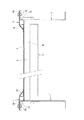
【図3】図1のI−I線一部省略断面図である。
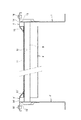
【図4】図1のII−II線一部省略断面図である。
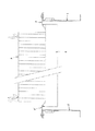
【図5】図1のIII−III線一部省略断面図である。
【符号の説明】
P 連結苗群
a 機台
b 受入ローラコンベア
c 送出ベルトコンベア
d 転載ベルトコンベア
e 列苗分離機構たる苗分離機構
f,f′ ベルト縁盛り上げ部材
1,1′ 側板
2 受入端側
3 回転ローラ
4 送出端側
5 前側ローラ
5′ 後側ローラ
6 テンションローラ
7 無端ベルト
8 底板
9 前側ローラ
9′ 後側ローラ
10 テンションローラ
11 無端ベルト
12 底板
13,13′ 上縁板
14,14′ 主板
15,15′ ベルトガイド
16,16′ 係止具
17,17′ 長孔[0001]
TECHNICAL FIELD OF THE INVENTION
TECHNICAL FIELD The present invention relates to a connected seedling group transfer device in a transplanter.
[0002]
[Prior art]
As the connected seedling group transport device in the transplanter, (1) Japanese Patent Application Laid-Open No. 4-210508 discloses a connected seedling group (aligned seedling) in which a number of seedlings such as a paper tube seedling are arranged in rows and columns. A pair of plate-shaped seedling guides are provided on both left and right sides in the conveying direction of a belt that conveys the connected seedling group toward an individual seedling separating mechanism (separating section) including a pair of rollers. It is fixed at a slightly wider interval than the width of the connected seedling group.
[0003]
(2) Japanese Patent No. 2652476 discloses a method for separating individual seedlings from a group of connected seedlings (aligned seedlings) in which a number of seedlings such as paper tube seedlings are arranged in rows and columns. A seedling guide (a seedling rotating body) composed of a pair of rotating belts is provided on both left and right sides in a transport direction of a belt for transporting the connected seedling group toward an individual seedling separating mechanism (separating unit) including a pair of rollers. It is provided at an interval in contact with the side surface of the group.
[0004]
(3) Japanese Patent No. 2853021 discloses a method for separating seedlings in a row, that is, a row of seedlings from a connected seedling group in which many seedlings such as paper tube seedlings are arranged in rows and columns. At the left and right sides in the transport direction of the belt for transporting the connected seedling group toward the row seedling separating mechanism (seed row separating section), a seedling biasing receiving rotating body composed of a pair of guide belts is slightly wider than the width of the linked seedling group. Provided at wide intervals.
[0005]
[Patent Document 1]
JP-A-4-210508 [Patent Document 2]
Japanese Patent No. 2652476 [Patent Document 3]
Japanese Patent No. 2853021
[Problems to be solved by the invention]
However, when the plate-shaped seedling guide of the above (1) is fixedly installed at an interval slightly wider than the width of the connected seedling group, if the interval is too wide, the position of the connected seedling group with respect to the individual seedling separation mechanism is reduced. The seedlings may shift or fall, and if the above interval is adjusted to the width of the connected seedling group, the seedlings are separated by friction because the side surface of the connected seedling group comes into contact with the plate-shaped seedling guide. It is worn out when it is done.
[0007]
In the case where the seedling guide composed of the rotating belt of the above (2) is provided, when the connecting seedling groups having different widths, that is, the wide connecting seedling group and the narrow connecting seedling group are arranged one after the other, the rotating belt is used. A group of connected seedlings that are conveyed while being guided in contact with the group and a group of connected seedlings that are not in contact with the rotating belt and are therefore conveyed without being guided are generated, and the position of the connected seedling group with respect to the individual seedling separation mechanism is shifted. Or the seedlings on the edge fall.
[0008]
Further, in the case where the seedling bias receiving and rotating body composed of the guide belt of the above (3) is provided at an interval slightly wider than the width of the connected seedling group, when the transplanter travels on the slope, the connected seedling group is moved to one side. The conveyed seedlings are conveyed while being brought into contact only with the guide belt, and consequently, the connected seedling group is conveyed to the row-seedling separating mechanism in a deviated state.
[0009]
The present invention eliminates the need for installation of the plate-shaped seedling guide, the seedling guide formed of a rotating belt or the seedling bias receiving rotating body itself, eliminates the above-mentioned various inconveniences, and separates the connected seedling group into individual seedling separating mechanisms or rows. It is intended to be accurately transported to the seedling separation mechanism.
[0010]
[Means for Solving the Problems]
The connected seedling group transfer device in the transplanting machine according to the first aspect of the present invention is provided on the left and right sides of the endless belts 7 and 11 of the belt conveyors c and d for transferring the connected seedling group P toward the seedling separation mechanism e.
[0011]
According to the second aspect of the present invention, the belt guides 15, 15, 15 ', 15' form an inclined plate body and support the endless belts 7, 11 and the bottom plate 8 for supporting the horizontal traveling section of the endless belts 7, 11. 2. The apparatus according to
[0012]
According to a third aspect of the present invention, the
[0013]
According to the fourth aspect of the present invention, the connected seedling group P is mounted on the receiving roller conveyor b while being housed in the predetermined seedling box, and only the connected seedling group P is reloaded by the rotation of the rotating
[0014]
BEST MODE FOR CARRYING OUT THE INVENTION
Hereinafter, the present invention will be described with reference to the illustrated embodiments.
[0015]
a is a machine composed of left and
[0016]
The connected seedling group P in which a large number of seedlings such as paper tube seedlings are arranged in rows and columns is accommodated in a predetermined seedling box, and the seedling box is mounted on the receiving roller conveyor b as it is and arranged in rows. Only the connected seedling group P is sent and transferred to the transfer belt conveyor d by the rotation of the rotating
The row seedlings are then separated into individual seedlings by an individual seedling separation mechanism (not shown), and are sorted into good seedlings and bad seedlings by a sorting mechanism.The bad seedlings are discharged out of the system, and only good seedlings are planted. And transplanted to the field.
[0017]
The endless belt 7 is rotatably stretched around a front roller 5, a rear roller 5 'and a tension roller 6 which are laterally stretched between the
[0018]
Further, the transfer belt conveyor d is endlessly connected to a front roller 9, a rear roller 9 'and a
[0019]
f and f 'are belt edge raising members slidably mounted on the left and right sides of the delivery belt conveyor c and the transfer belt conveyor d with respect to the
[0020]
The belt edge raising members f, f 'are the inner ends of the elongated
[0021]
[0022]
According to the present apparatus having the above configuration, when a predetermined seedling box containing the connected seedling group P is mounted on the receiving roller conveyor b, the connected seedling group P is moved from the seedling box to the transfer belt conveyor d by the rotation of the
[0023]
Although the above-described seedling separation mechanism e has been described in the form of adopting the row seedling separation mechanism, the present invention is not limited to this, and it is apparent that an individual seedling separation mechanism that directly separates individual seedlings from a connected seedling group may be used. is there.
[0024]
【The invention's effect】
As apparent from the above description, the present invention has the following effects.
[0025]
That is, a belt guide is provided on both the left and right sides of the endless belt in the conveying direction of the belt conveyor that conveys the connected seedling group toward the seedling separation mechanism, and a belt guide that raises the edge of the endless belt in the horizontal traveling section is provided. When traveling on a slope, even if the connected seedling group is deviated to one side, it stays in contact with the bulge of the edge, and does not hinder the transport of the connected seedling group, and It can be accurately transported and supplied to the separation mechanism.
[0026]
Therefore, as in the related art, a plate-shaped seedling guide, a seedling guide formed of a rotating belt, a seedling bias receiving rotating body, or the like is installed separately from the belt for transporting the linked seedling group, and the linked seedling group is transported during transport. There are no disadvantages as described above in preventing deviation.
[0027]
Further, as in claim 2, the belt guide is composed of an inclined plate body, and the edge of the endless bell is raised by the slope, and the belt guide supports the endless belt and its horizontal traveling section. The belt guide is inserted between the bottom plate and the belt guide, and the belt guide is slidable inward and outward relative to an upper edge plate of a side plate of a machine on which a belt conveyor is erected. The one formed at the inner end of the main plate which has been polymerized and tightened has a simple structure, is low in manufacturing cost, has no risk of failure, and is extremely preferable in practice.
[0028]
According to the fourth aspect, the connected seedling group is mounted on the receiving roller conveyor while being housed in the predetermined seedling box, and thereafter, only the connected seedling group is held at the predetermined position by the transfer belt conveyor and the sending belt conveyor. It can be transported accurately to the seedling separation mechanism.
[Brief description of the drawings]
FIG. 1 is a plan view of a connected seedling group transport device according to an embodiment of the present invention.
FIG. 2 is a longitudinal sectional view of the same.
FIG. 3 is a partially omitted sectional view taken along line II of FIG. 1;
FIG. 4 is a partially omitted sectional view taken along line II-II of FIG. 1;
FIG. 5 is a partially omitted sectional view taken along line III-III of FIG. 1;
[Explanation of symbols]
P Connected seedling group a Machine stand b Receiving roller conveyor c Sending belt conveyor d Transfer belt conveyor e Row seedling separating mechanism f, f 'Seedling
Claims (4)
Priority Applications (1)
| Application Number | Priority Date | Filing Date | Title |
|---|---|---|---|
| JP2002375473A JP3947929B2 (en) | 2002-12-25 | 2002-12-25 | Linked seedling transport device in transplanter |
Applications Claiming Priority (1)
| Application Number | Priority Date | Filing Date | Title |
|---|---|---|---|
| JP2002375473A JP3947929B2 (en) | 2002-12-25 | 2002-12-25 | Linked seedling transport device in transplanter |
Publications (2)
| Publication Number | Publication Date |
|---|---|
| JP2004201596A true JP2004201596A (en) | 2004-07-22 |
| JP3947929B2 JP3947929B2 (en) | 2007-07-25 |
Family
ID=32813216
Family Applications (1)
| Application Number | Title | Priority Date | Filing Date |
|---|---|---|---|
| JP2002375473A Expired - Fee Related JP3947929B2 (en) | 2002-12-25 | 2002-12-25 | Linked seedling transport device in transplanter |
Country Status (1)
| Country | Link |
|---|---|
| JP (1) | JP3947929B2 (en) |
Cited By (1)
| Publication number | Priority date | Publication date | Assignee | Title |
|---|---|---|---|---|
| CN117142078A (en) * | 2023-07-31 | 2023-12-01 | 益阳富佳科技有限公司 | An efficient production line for catching and placing seedling trays |
-
2002
- 2002-12-25 JP JP2002375473A patent/JP3947929B2/en not_active Expired - Fee Related
Cited By (1)
| Publication number | Priority date | Publication date | Assignee | Title |
|---|---|---|---|---|
| CN117142078A (en) * | 2023-07-31 | 2023-12-01 | 益阳富佳科技有限公司 | An efficient production line for catching and placing seedling trays |
Also Published As
| Publication number | Publication date |
|---|---|
| JP3947929B2 (en) | 2007-07-25 |
Similar Documents
| Publication | Publication Date | Title |
|---|---|---|
| US5983812A (en) | Seedling with soil selecting and transporting apparatus for transplanting machine | |
| EP1142465A2 (en) | Method and apparatus for regulating interval of seedlings | |
| US6945530B2 (en) | Device for conveying stacks of sheets of paper | |
| JP3947929B2 (en) | Linked seedling transport device in transplanter | |
| US7278250B2 (en) | Sliced bread packaging method and equipment | |
| JPH0638012Y2 (en) | Conveying device for fruits and vegetables | |
| EP0554100B1 (en) | Continuous belt | |
| JPH0325386B2 (en) | ||
| JPH0748007Y2 (en) | Transplanter seedling selection and transport device | |
| JPH0748006Y2 (en) | Transplanter seedling selection and transport device | |
| JPH0512U (en) | Transplanter seedling selection and transport device | |
| JP3071374B2 (en) | Seedling turning device | |
| JP3110723B2 (en) | Seedling supply device | |
| JP2823521B2 (en) | Transplanter seedling supply device | |
| JP3662397B2 (en) | Conveying device for integrated packaging of packaging sheets | |
| JPH0733610Y2 (en) | Paper tube seedling selection and transport device for transplanter | |
| JP2860196B2 (en) | Transplanter seedling alignment device | |
| JP3593173B2 (en) | Transplanter seedling supply device | |
| JPH0437372Y2 (en) | ||
| JP2899222B2 (en) | Agricultural and seedling supply equipment | |
| JP2819494B2 (en) | A device that supplies a group of linked seedlings to the seedling separation unit | |
| JP2001045813A (en) | Transplanter seedling supply device | |
| JPH05153812A (en) | Device for delivering seedling and stem of transplanter | |
| JPH09172820A (en) | Seeding machine | |
| JPH09118426A (en) | Device for feeding long agricultural product in alignment |
Legal Events
| Date | Code | Title | Description |
|---|---|---|---|
| A621 | Written request for application examination |
Free format text: JAPANESE INTERMEDIATE CODE: A621 Effective date: 20050530 |
|
| A977 | Report on retrieval |
Free format text: JAPANESE INTERMEDIATE CODE: A971007 Effective date: 20060929 |
|
| A131 | Notification of reasons for refusal |
Free format text: JAPANESE INTERMEDIATE CODE: A131 Effective date: 20061010 |
|
| A521 | Request for written amendment filed |
Free format text: JAPANESE INTERMEDIATE CODE: A523 Effective date: 20061120 |
|
| TRDD | Decision of grant or rejection written | ||
| A01 | Written decision to grant a patent or to grant a registration (utility model) |
Free format text: JAPANESE INTERMEDIATE CODE: A01 Effective date: 20070313 |
|
| A61 | First payment of annual fees (during grant procedure) |
Free format text: JAPANESE INTERMEDIATE CODE: A61 Effective date: 20070404 |
|
| R150 | Certificate of patent or registration of utility model |
Ref document number: 3947929 Country of ref document: JP Free format text: JAPANESE INTERMEDIATE CODE: R150 Free format text: JAPANESE INTERMEDIATE CODE: R150 |
|
| FPAY | Renewal fee payment (event date is renewal date of database) |
Free format text: PAYMENT UNTIL: 20100427 Year of fee payment: 3 |
|
| S111 | Request for change of ownership or part of ownership |
Free format text: JAPANESE INTERMEDIATE CODE: R313113 |
|
| FPAY | Renewal fee payment (event date is renewal date of database) |
Free format text: PAYMENT UNTIL: 20100427 Year of fee payment: 3 |
|
| R350 | Written notification of registration of transfer |
Free format text: JAPANESE INTERMEDIATE CODE: R350 |
|
| FPAY | Renewal fee payment (event date is renewal date of database) |
Free format text: PAYMENT UNTIL: 20100427 Year of fee payment: 3 |
|
| FPAY | Renewal fee payment (event date is renewal date of database) |
Free format text: PAYMENT UNTIL: 20110427 Year of fee payment: 4 |
|
| FPAY | Renewal fee payment (event date is renewal date of database) |
Free format text: PAYMENT UNTIL: 20120427 Year of fee payment: 5 |
|
| FPAY | Renewal fee payment (event date is renewal date of database) |
Free format text: PAYMENT UNTIL: 20120427 Year of fee payment: 5 |
|
| FPAY | Renewal fee payment (event date is renewal date of database) |
Free format text: PAYMENT UNTIL: 20130427 Year of fee payment: 6 |
|
| S111 | Request for change of ownership or part of ownership |
Free format text: JAPANESE INTERMEDIATE CODE: R313114 |
|
| FPAY | Renewal fee payment (event date is renewal date of database) |
Free format text: PAYMENT UNTIL: 20130427 Year of fee payment: 6 |
|
| R350 | Written notification of registration of transfer |
Free format text: JAPANESE INTERMEDIATE CODE: R350 |
|
| FPAY | Renewal fee payment (event date is renewal date of database) |
Free format text: PAYMENT UNTIL: 20130427 Year of fee payment: 6 |
|
| FPAY | Renewal fee payment (event date is renewal date of database) |
Free format text: PAYMENT UNTIL: 20140427 Year of fee payment: 7 |
|
| LAPS | Cancellation because of no payment of annual fees |