【0001】
【発明の属する技術分野】
本発明は、ビル、家屋等の屋上に植物生育環境を造成する屋上緑化に使用できる排水用基盤材、該基盤材を用いた屋上緑化設備および屋上緑化方法に関する。
【0002】
【従来の技術】
近年、都市部においてビルや家屋等の構造物の屋上(屋根を含む)に植物の生育環境を造成する屋上緑化が進められている。屋上緑化設備は、ビル等の屋上に敷設するものであるから、軽量であること、施工が容易であること、排水性が良好であること、培土の飛散が少ないこと等が要求される。これらの要求を満足するため、これまで数々の提案がなされている(例えば、特許文献1〜3)。
【0003】
特許文献1は、空隙率90%以上、見掛け密度5〜100kg/m3、厚さ20〜100mmの熱可塑性樹脂繊維構造体を植生基材とするものである。また、特許文献2は、熱可塑性樹脂重合体よりなる0.1〜5mm径の連続線上体の多数本が、互いに交差しながら各々水平方向ならびに厚み方向に不規則あるいは規則的に屈曲して一方側から他方側に向けて延び、互いに交差するポイントにおいて融着されてなる立体網状構造体からなる屋上緑化用マットに関するものである。
【0004】
しかし、上記特許文献1および特許文献2では、繊維構造体や網目状構造体に培土を充填するため、培土の流出や飛散は防止できるものの、繊維構造体や網目状構造体が目詰まりを起こし易く排水性が低下する。
【0005】
特許文献3では、繊度の異なる2種以上の捲縮繊維からなる混合ウェブがランダム配列して積層され、厚さ方向の一方側に主として細繊度繊維ウェブ層が分布し、他方側に太繊度繊維ウェブ層が分布し、その間に連続的に密度勾配が形成され、かつ繊維同士の接点が接着固定された繊維成形体と、ポリオレフィン樹脂製の排水層を備えた緑化構造物が提案されている。この特許文献3では、培土を充填した繊維成形体とは別に排水層を設けている点で雨水等の排出は確保されている。しかし、排水層については、実施例中で太デニールのポリエステル繊維にクリンプを施した繊維スプリング(カールロック;商品名、東亜紡績株式会社製)が使用されている以外は具体的構造は明示されていない。
【0006】
一方、ゴルフ練習場グランドの表層構造等として、表地組織が6角形あるいは菱形模様のハニカム状の組織であり、表裏の地組織が連結糸で連結されてなり、地組織および連結糸に合成繊維の原着糸を用いた立体布帛を用いることが提案されている(特許文献4、特許文献5)。しかし、これらの立体布帛を屋上緑化設備の資材として用いることは一切述べられていない。
【0007】
【特許文献1】
特開2002−10711号公報
【特許文献2】
特開2001−145422号公報
【特許文献3】
特開2002−125452号公報
【特許文献4】
実用新案登録第2572655号公報
【特許文献5】
実用新案登録第2517240号公報
【0008】
【発明が解決しようとする課題】
上記したように、従来の屋上緑化設備においては、繊維構造体を使用することが知られているが、その役割は培土を保持するというものである。培土からの排水を促すために繊維構造体を用いた排水層を設けている場合でも、その構造については深く検討されていない。
【0009】
しかし、屋上緑化設備において排水機能が低下すると、設備の荷重が大幅に増加して建造物にかかる負担が非常に大きくなるほか、植物や培土の腐敗を招き、屋上環境を台無しにしてしまうおそれもある。
【0010】
また、屋上緑化設備の排水性を確保するために、スノコのような硬い材質の骨格材を排水層に使用することも考えられるが、重量がかさむ上、地表面と同様の感触(例えば踏圧荷重に対する適度な弾性)を与えることができない。他方、排水層に柔らか過ぎる骨格材を用いた場合、培土表面の弾性は得られても土圧や踏圧に対する耐性がなくなり、荷重によって培土が移動したり、崩壊したりして植物の根が損傷し、枯死させてしまうおそれがある。
【0011】
本発明は、上記実情に鑑みてなさたものであり、十分な排水性を確保しながら、軽量化を図ることが可能な屋上緑化設備を提供することを課題とするものである。
【0012】
【課題を解決するための手段】
上記課題を解決するため、本発明の第1の態様に係る屋上緑化設備の排水用基盤材は、表側または裏側の地組織のうち、少なくとも片側がメッシュ状に形成されており、かつ表側と裏側の地組織が連結糸で連結されることにより厚みをもって形成された、内部に空隙を有する三次元編織物であることを特徴とする。
【0013】
この屋上緑化設備の排水用基盤材の発明によれば、空隙を有する三次元編織物により、これを配備した屋上緑化設備において十分な排水性を確保できるとともに、軽量化を図ることができる。
【0014】
本発明の第2の態様に係る屋上緑化設備の排水用基盤材の発明は、第1の態様において、前記表側および/または裏側の地組織をバインダー樹脂により溶融固着させたことを特徴とする。この特徴によれば、地組織をバインダー樹脂により溶融固着したので、押圧に対する抵抗性を大幅に高めることができる。よって、バインダー樹脂による補強度合いを調整することにより、所望の弾力性を持つ屋上緑化設備を作り出すことができる。
【0015】
本発明の第3の態様に係る屋上緑化設備の発明は、第1の態様または第2の態様の排水用基盤材を備えたことを特徴とする。この特徴によれば、屋上緑化設備において第1の態様または第2の態様と同様の作用効果が得られる。
【0016】
本発明の第4の態様に係る屋上緑化方法の発明は、屋上面に、防根シートを敷設し、その上層に請求項1または請求項2に記載の排水用基盤材を敷設した後、さらにその上層に培土層を設け、該培土層において植物を育成することを特徴とする。この特徴によれば、屋上緑化方法において、上記第1の態様または第2の態様と同様の作用効果が得られる。また、本発明方法で使用する排水用基盤材は、軽量である上、ロール状に巻回して持ち運びでき、施工場所において展延するだけでよいため、施工が極めて容易で、短時間での作業を可能にする。
【0017】
本発明の第5の態様に係る屋上緑化設備の発明は、植物を植え込む土壌を備えた培土層と、該培土層からの水分の排出を促すための空隙を有する排水層と、を備えた屋上緑化設備であって、前記排水層に、柔軟性を有する排水用基盤材を備えたことを特徴とする。この特徴によれば、柔軟性を有する排水用基盤材を備えたので、屋上緑化設備において十分な排水性を確保できるとともに、表面に適度な弾力感を与えることができる。
【0018】
本発明の第6の態様に係る屋上緑化設備の発明は、第5の態様において、前記排水用基盤材は、表側あるいは裏側の地組織のうち、少なくとも片側がメッシュ状に形成され、かつ表側と裏側の地組織が連結糸で連結されることにより厚みをもって形成された、内部に空隙を有する三次元編織物であることを特徴とする。この特徴によれば、内部に空隙を有する三次元編織物の排水用基盤材により、排水性を確保しながら屋上緑化設備の軽量化を図ることができる。
【0019】
本発明の第7の態様に係る屋上緑化設備の発明は、第6の態様において、前記培土層が、キトサン圧入シラスを含有することを特徴とする。この特徴によればキトサン圧入シラスを含有する培土層により、軽量化を図りつつ植物の生長を促すことができる。
【0020】
【発明の実施の形態】
以下、図面に基づき本発明の実施の形態を説明する。
図1は、本発明の一実施形態にかかる屋上緑化設備100の断面構造を模式的に示す図面である。この屋上緑化設備100は、屋上のコンクリート地50の表面に防根シート40を敷設し、その上に排水層として排水性基盤材30が敷設され、排水性基盤材30の上には、セパレーター20が設けられ、さらにその上に培土層としてシラス軽量土10が盛土されている。植物60はシラス軽量土10に定植されている。
【0021】
シラス軽量土10は、シラスを主成分として含有する培土組成物である。シラスは、日本国宮崎県南部から鹿児島県東部の大隈半島に至る地域に形成された、4700km2に及ぶ広大なシラス台地を構成する発泡性ケイ酸岩で、多孔質で比重が軽いという特徴を持つ土壌である。シラスを主成分とする培土組成物を用いることによって、後記するように屋上緑化設備の大幅な軽量化が可能になる。
【0022】
本実施形態では、シラスに天然多糖類であるキトサンを圧入処理したキトサン圧入シラスを用いている。キトサンは、周知のとおりカニやエビなどの甲殻類、昆虫、貝類、きのこなどの菌類の細胞壁に多く含まれる多糖類の天然高分子であり、植物の発芽、生長を促し、健全な植物を育てる効果があるので、土壌改良材、活力促進剤として市場で販売されている。
【0023】
キトサン圧入シラスは、例えば粒径3〜8mm程度のシラスに、減圧真空圧入法によりキトサンを圧入処理したものである。減圧真空圧入は以下に例示する方法により行われる。すなわち、注入用コンテナに500リットルのシラスを投入し、注入機本体にセットし、キトサン液を入れ、一気に減圧し真空状態にしてシラスの気孔中にキトサンを注入する。このとき、シラスの気孔から気泡が排出されて気孔自体が真空状態となるので、空気の替りに気孔の奥深くまでキトサンが侵入する。キトサンの圧入は、シラス500リットルに対し3時間程度かけて行うことが好ましい。使用するキトサン溶液の濃度は、例えば0.002モル/リットル(原液の500倍に相当)程度が好ましい。
【0024】
キトサンを圧入処理することにより、シラスに乏しい有機物を補うことができるとともに、圧入によって多孔質のシラスの気孔中にキトサンが侵入し、粒子の中心部までキトサンが充填される。これにより、通常の浸漬処理に比べてキトサンの含有量を各段に高めることができるとともに、単にシラス培土中にキトサンを添加する場合に比べて徐放作用が得られ、雨水等により一度にキトサンが流出してしまう事態を防ぐことができる。つまり、キトサンを持続的に作用させることができる。
【0025】
シラス軽量土10は、キトサン圧入シラスを主成分とするものであればよいが、これ以外の成分として、例えば鹿沼土、バーク堆肥、木炭等を配合することが好ましい。これらの成分は、いずれも軽量でありなから植物体を支持する培土としての機能を果たし得るものであるため、軽量化が最優先課題である屋上緑化設備に適したものである。シラス軽量土10における各成分の配合比は任意であるが、軽量化と植物の生育状態とを比較考量した結果では、キトサン圧入シラスと鹿沼土とバーク堆肥と木炭とを、6:2:1:1の割合で配合したものが特に好ましいことが判明している。かかる配合比において、シラス軽量土10の湿潤密度は0.67g/cm3、乾燥密度は0.39g/cm3となる。自然土壌の通常時密度は1.6〜1.8g/cm3、市販の軽量土でも0.6〜0.8g/cm3であるから、本発明のシラス軽量土10は、屋上緑化用の培土として望ましい軽量土壌であることが理解される。また、上記組成におけるシラス軽量土10のpH(H2O)は6.89程度、有効水分量は165リットル/m3、透水係数は4.5×10−3cm/sec程度となり、培土として適度な保水/透水性能を持つものとなる。
【0026】
シラス軽量土10を用いた培土層の厚みは、育成する植物の種類により異なるが、概ね5〜50cm程度とすることができる。
【0027】
セパレーター20は、シラス軽量土10が排水用基盤材30の空隙へ落下し、排水層の目詰まりを引き起こすことを防止する役割を果たす網目状のシート部材であり、その材質は問わないが、腐蝕や劣化が起こり難い材質として一般に使用されているポリエステル、ナイロン、ポリエチレンもしくはポリプロピレンから構成されたもの、またはこれらの表面に被覆樹脂加工が施された合成樹脂製の材質が好ましい。セパレーター20の網目の目合いは、シラス軽量土10の粒径に応じて選択すればよい。セパレーター20の厚みは、0.15〜0.50mm程度とすることができる。
【0028】
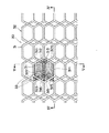
排水用基盤材30は、表側または裏側の地組織のうち、少なくとも片面がメッシュ状もしくは溝状の空隙を形成し、かつ表側と裏側の地組織が連結糸で連結されて厚みを形成する三次元編織物である。この三次元編織物としては、図2〜図5に詳細を例示するように、表側および裏側の地組織が六角形のメッシュ状に形成され、連結糸が表裏の六角形の地組織を連結する構造のものが好ましく用いられる。
【0029】
図2は、排水用基盤材30の要部斜視図であり、図3は同要部平面図、図4は図3のIV−IV線矢視の断面図、図5は図3のV−V線矢視の断面図である。なお、図2および図3では、説明の便宜上、表裏の地組織31、32を架橋するように連結している連結糸33は、部分的にのみ図示している。
【0030】
表側の地組織31を構成する地糸311および地糸314は、主に裏側の地組織32を構成する地糸322との間で複数本の弓状の連結糸33により結ばれている(図4参照)。換言すれば、裏側の地糸322から連結糸33が二方向に延び、表側の地糸311および314に接続している(図5参照)。また、表側の地糸315と裏側の地糸325、表側の地糸316と裏側の地糸323が、それぞれ連結糸33により接続されている。同様にして、連結糸により表裏のメッシュ状の地組織31と32とが架橋されハニカム状の空隙を持つ複雑な立体網目構造が形成されている。かかる構造により、土壌や植物の荷重が加えられても、立体網目内部の空隙が十分に確保され排水性が損なわれることなく維持される。また、柔軟性を持つ立体網目構造により、踏圧に対する適度な弾性を与えることができるようになる。さらに、排水用基盤材30は空隙率が85〜98%と高いため、例えば0.5〜3.5cmの厚みで十分に排水機能を持つことから、排水層を薄層化できるようになる。従って、所要の排水機能を維持しながら屋上緑化設備100を低層化することができるとともに、強風に対する耐久性も高めることができる。また、排水用基盤材30が柔軟性に富み、かつ薄型であれば、ロール状に巻回して屋上ヘ搬入し、そこで展延することにより容易に施工できるという利点もある。
【0031】
排水用基盤材30の材質は、腐蝕や劣化し難い合成樹脂繊維が好ましく、特にポリエステル繊維が好ましい。排水用基盤材30としての三次元編織物を構成する糸の径は、0.15〜0.5mm程度(220〜2,350デニール)が好ましく、地組織のメッシュの開口径(目合い)は10〜50mm程度が好ましい。また、三次元編織物の高さ(すなわち、表裏の地組織間の距離;厚さ)は、前記したように緑化設備の低層化や巻回のし易さを考慮すると8〜40cm程度、好ましくは10〜30cm程度にすることができる。
【0032】
また、本実施形態の排水用基盤材30においては、裏側の地組織32をバインダー繊維により溶融固着させている。より具体的には、裏側の地組織32を構成する繊維中に、バインダー繊維として、図6に示すように低融点のポリエステル繊維132を外周に有し、内側に通常の融点を持つポリエステル樹脂133を入れた芯鞘構造の繊維を挿入している。ここで、低融点のポリエステル樹脂132としては、例えば160℃程度の融点を有する共重合ポリエチレンテレフタレートを挙げることができ、通常の融点を有するポリエステル樹脂133としては、例えば260℃程度の融点を持つポリエチレンテレフタレートを挙げることができる。この芯鞘構造の複合繊維は、モノフィラメント、マルチフィラメントおよび短繊維糸条のいずれで構成されてもよい。複合繊維の太さは、100デニール以上〜1000デニール以下が編み立て性が良好で使用し易いこと、および交点部の接着力に優れている点で好適である。なお、芯鞘比は、期待する物性に応じて設定できるが、本発明においては1:4〜4:1の範囲とすることが好ましい。なお、バインダー繊維は裏側の地組織32だけでなく、表側の地組織31に導入してもよく、あるいは表裏両側に導入してもよい。
【0033】
かかる芯鞘構造の繊維を表側および/または裏側の地組織31、32に混入して三次元編織物を形成した後、例えば160℃以上の温度を加えた後冷却する熱セット加工を行うことにより、鞘の部分の低融点ポリエチレン樹脂132が一旦溶融し、周囲の繊維との接点において固着するので地組織が強固なものとなる。これにより踏圧に対する抵抗性を大幅に向上させることができる。これは、地組織が強固になると、三次元編織物への重力方向の押圧に対して連結糸33が横倒しにくくなり、適度な弾性を維持した状態で荷重に耐え得るようになるためである。また、排水用基盤材30が土圧や踏圧に対して十分な耐性を有する結果として、植物への悪影響(軽量土の崩れや移動による根の損傷など)も防ぐことができる。
【0034】
防根シート40は、排水層まで到達した植物根が屋上のコンクリート地50に定着することを防ぐ役割を果たすものであり、水分を透過しない合成樹脂等の材質のシート部材を用いることが好ましい。防根シート40の厚みは0.2〜1.5mm程度とすることができる。
【0035】
本発明の屋上緑化設備100において生育させ得る植物は、特に限定されるものではないが、例えば、芝などの低草類、セダムなどの多肉植物、本格緑化用の中低木類などから、目的に応じて選択することができる。
【0036】
本発明の屋上緑化方法は、例えばロール状に巻回した状態の防根シート40、排水性基盤材30、セパレーター20を屋上面で順次展開、積層していき、セパレーター20の上にシラス軽量土10を盛土、あるいは充填した後、植物を植え込むことにより行うことができる。
【0037】
また、栽培する植物種が芝の場合は、別の栽培地でシラス軽量土10と一体に育成したマット状の芝をロール状に巻回して搬入し、セパレーター20上に展開することによって施工することもできる。
【0038】
以上、本発明を種々の実施形態に関して述べたが、本発明は上記実施形態に制約されるものではなく、特許請求の範囲に記載された発明の範囲内で、他の実施形態についても適用可能である。
【0039】
例えば、図1の屋上緑化設備100では、培土層であるシラス軽量土10が表層を形成しているが、例えば低木植物61などを植える本格緑化の場合には、図7に例示するように、培土層の上に、さらに水分蒸発抑制や雑草の発芽抑制の目的で砂利やバークチップ等で覆うマルチング層70を設けることができる。
【0040】
また、排水層は、培土層と積層する構成とは限らず、図7のように排水用基盤材30の側部をシラス軽量土10で覆うようにしてもよい。図7では、排水用基盤材30は、水の排出路が形成できるように勾配方向に沿って複数並列配備されている。この場合、排水性基盤材30内への培土の侵入を防ぐため、排水性基盤材30の上部だけでなく側部もセパレーター20で覆うことが好ましい。
【0041】
【発明の効果】
本発明の空隙をする三次元編織物である排水用基盤材により、これを配備した屋上緑化設備において十分な排水性を確保できるとともに、軽量化を図ることができる。
【図面の簡単な説明】
【図1】本発明の一実施形態に係る屋上緑化設備の断面構造を示す模式図。
【図2】本発明の一実施形態に係る排水性基盤材の要部斜視図。
【図3】本発明の一実施形態に係る排水性基盤材の要部平面図。
【図4】本発明の一実施形態に係る排水性基盤材の要部断面図。
【図5】本発明の一実施形態に係る排水性基盤材の要部断面図。
【図6】芯鞘型複合繊維の断面構造を示す模式図。
【図7】本発明の別の実施形態に係る屋上緑化設備の断面構造を示す模式図。
【符号の説明】
10 シラス軽量土
20 セパレーター
30 排水性基盤材
40 防根シート
50 コンクリート
60 植物
70 マルチング層
100、101 屋上緑化設備[0001]
TECHNICAL FIELD OF THE INVENTION
The present invention relates to a drainage base material that can be used for rooftop greening for creating a plant growth environment on a rooftop of a building, a house, and the like, a rooftop greening facility using the base material, and a rooftop greening method.
[0002]
[Prior art]
BACKGROUND ART In recent years, rooftop greening has been promoted to create a plant growth environment on the rooftop (including the roof) of structures such as buildings and houses in urban areas. Since the rooftop greening equipment is laid on the rooftop of a building or the like, it is required that the rooftop greenery be lightweight, easy to construct, have good drainage properties, and have little scattering of soil. In order to satisfy these requirements, various proposals have been made so far (for example, Patent Documents 1 to 3).
[0003]
Patent Literature 1 uses a thermoplastic resin fiber structure having a porosity of 90% or more, an apparent density of 5 to 100 kg / m 3 , and a thickness of 20 to 100 mm as a vegetation base material. Further, Patent Document 2 discloses that a large number of continuous linear bodies each having a diameter of 0.1 to 5 mm made of a thermoplastic resin polymer are bent irregularly or regularly in a horizontal direction and a thickness direction while intersecting each other. The present invention relates to a rooftop greening mat formed of a three-dimensional net-like structure extending from one side to the other side and fused at points crossing each other.
[0004]
However, in Patent Document 1 and Patent Document 2, since the fibrous structure and the mesh-like structure are filled with the cultivation soil, the outflow and scattering of the cultivation soil can be prevented, but the fibrous structure and the mesh-like structure are clogged. Easily drained.
[0005]
In Patent Document 3, a mixed web composed of two or more types of crimped fibers having different finenesses is randomly arranged and laminated, and a fine fineness fiber web layer is mainly distributed on one side in a thickness direction, and a large fineness fiber is distributed on the other side. A greening structure having a fiber molded body in which web layers are distributed, a density gradient is continuously formed between the web layers, and a contact point between fibers is fixedly adhered, and a drainage layer made of a polyolefin resin has been proposed. In Patent Literature 3, the drainage layer is provided separately from the fiber molded body filled with the cultivated soil, thereby ensuring the discharge of rainwater and the like. However, the specific structure of the drainage layer is specified except for the use of a fiber spring (Curl Rock; trade name, manufactured by Toa Boseki Co., Ltd.) in which crimped thick denier polyester fiber is used in the examples. Absent.
[0006]
On the other hand, as the surface layer structure of the golf driving range ground, the surface fabric is a hexagonal or rhombic honeycomb-like structure, and the ground fabrics on the front and back are connected by connecting yarns. It has been proposed to use a three-dimensional fabric using original yarn (Patent Documents 4 and 5). However, there is no mention of using these three-dimensional fabrics as materials for rooftop greening equipment.
[0007]
[Patent Document 1]
Japanese Patent Application Laid-Open No. 2002-10711 [Patent Document 2]
JP 2001-145422 A [Patent Document 3]
Japanese Patent Application Laid-Open No. 2002-125452 [Patent Document 4]
Japanese Utility Model Registration No. 2572655 [Patent Document 5]
Japanese Utility Model Registration No. 2517240
[Problems to be solved by the invention]
As described above, in a conventional rooftop greening facility, it is known to use a fibrous structure, but its role is to maintain soil cultivation. Even when a drainage layer using a fibrous structure is provided to encourage drainage from the soil, its structure has not been studied in depth.
[0009]
However, if the drainage function of the rooftop greening equipment deteriorates, the load on the equipment will increase significantly, and the burden on the building will become extremely large.In addition, the plants and cultivated soil will rot, and the rooftop environment may be ruined. is there.
[0010]
In order to ensure the drainage performance of the rooftop greening equipment, it is conceivable to use a skeletal material made of a hard material such as snowboard for the drainage layer. However, the weight increases and the feel similar to the ground surface (for example, treading load) (Appropriate elasticity to On the other hand, if the drainage layer is made of too soft skeletal material, the soil on the cultivation surface will have elasticity, but will not be resistant to earth pressure or tread pressure. And may die.
[0011]
The present invention has been made in view of the above circumstances, and has as its object to provide a rooftop greening facility capable of reducing the weight while ensuring sufficient drainage.
[0012]
[Means for Solving the Problems]
In order to solve the above-mentioned problem, the drainage base material of the rooftop greening facility according to the first aspect of the present invention has at least one side of a ground structure on a front side or a back side formed in a mesh shape, and has a front side and a back side. Characterized in that it is a three-dimensional knitted fabric having voids inside formed by connecting the ground textures with connecting yarns.
[0013]
According to the invention of the drainage base material for the rooftop greening facility, the three-dimensional knitted fabric having the voids can ensure sufficient drainage in the rooftop greening facility in which the three-dimensional knitted fabric is provided, and can reduce the weight.
[0014]
The invention of a drainage base material for a rooftop greening facility according to a second aspect of the present invention is characterized in that, in the first aspect, the ground structure on the front side and / or the back side is melt-fixed with a binder resin. According to this feature, since the ground structure is melted and fixed by the binder resin, the resistance to pressing can be greatly increased. Therefore, by adjusting the degree of reinforcement by the binder resin, a rooftop greening facility having a desired elasticity can be created.
[0015]
The invention of a rooftop greening facility according to a third aspect of the present invention is characterized by including the drainage base material of the first aspect or the second aspect. According to this feature, the same effect as the first or second aspect can be obtained in the rooftop greening facility.
[0016]
The invention of the rooftop greening method according to the fourth aspect of the present invention is that, after laying a root protection sheet on the rooftop surface and laying the drainage base material according to claim 1 or 2 on the upper layer, A cultivation layer is provided as an upper layer, and plants are grown in the cultivation layer. According to this feature, in the rooftop greening method, the same operation and effect as those in the first or second embodiment can be obtained. In addition, the drainage base material used in the method of the present invention is lightweight, can be carried around in a roll, can be carried around, and needs only to be spread at a construction site. Enable.
[0017]
The invention of the rooftop greening equipment according to the fifth aspect of the present invention is a rooftop comprising: a cultivation layer provided with soil into which plants are planted; and a drainage layer having a void for promoting the discharge of moisture from the cultivation layer. A greening facility, wherein the drainage layer is provided with a flexible drainage base material. According to this feature, since the drainage base material having flexibility is provided, a sufficient drainage property can be secured in the rooftop greening facility, and a suitable elasticity can be given to the surface.
[0018]
The invention of the rooftop greening equipment according to the sixth aspect of the present invention, in the fifth aspect, in the drainage base material, at least one side of the ground texture on the front side or the back side is formed in a mesh shape, and It is characterized by being a three-dimensional knitted fabric having a space inside, formed with a thickness by connecting the ground structure on the back side with a connecting yarn. According to this feature, the drainage base material of the three-dimensional knitted fabric having voids therein can reduce the weight of the rooftop greening facility while ensuring drainage.
[0019]
The invention of a rooftop greening facility according to a seventh aspect of the present invention, in the sixth aspect, is characterized in that the cultivation layer contains chitosan press-fitted shirasu. According to this feature, the cultivation layer containing chitosan press-fitted shirasu can promote the growth of plants while reducing the weight.
[0020]
BEST MODE FOR CARRYING OUT THE INVENTION
Hereinafter, embodiments of the present invention will be described with reference to the drawings.
FIG. 1 is a drawing schematically showing a cross-sectional structure of a rooftop greening facility 100 according to one embodiment of the present invention. In this rooftop greening facility 100, a root protection sheet 40 is laid on the surface of a concrete ground 50 on the roof, a drainage base material 30 is laid thereon as a drainage layer, and a separator 20 is placed on the drainage base material 30. Is provided thereon, and a shirasu lightweight soil 10 is embanked thereon as a cultivation layer. The plant 60 is planted on the shirasu lightweight soil 10.
[0021]
The shirasu lightweight soil 10 is a cultivated soil composition containing shirasu as a main component. Silas, was formed in the area leading to the Okuma peninsula of eastern Kagoshima Prefecture from southern Miyazaki Prefecture, Japan, in the foaming silicate rock that make up the vast Shirasu plateau of up to 4700km 2, characterized in that the specific gravity of a porous The soil that has. By using the soil cultivation composition containing shirasu as a main component, the rooftop greening equipment can be significantly reduced in weight as described later.
[0022]
In the present embodiment, chitosan-injected shirasu is used in which chitosan, which is a natural polysaccharide, is injected into shirasu. As is well known, chitosan is a natural polymer of polysaccharides abundant in the cell walls of crustaceans such as crabs and shrimps, insects, shellfish, fungi such as mushrooms, and promotes germination and growth of plants and grows healthy plants. Because it is effective, it is sold on the market as a soil conditioner and a vitality enhancer.
[0023]
The chitosan press-fitting shirasu is obtained by press-fitting chitosan into a shirasu having a particle diameter of, for example, about 3 to 8 mm by a reduced-pressure vacuum press-fitting method. The reduced pressure vacuum injection is performed by the method exemplified below. That is, 500 liters of shirasu is put into an infusion container, set in the main body of the injecting machine, a chitosan solution is put into the container, and the pressure is reduced at a stretch to make a vacuum and chitosan is injected into pores of the shirasu. At this time, air bubbles are exhausted from the pores of the shirasu, and the pores themselves are in a vacuum state, so that chitosan penetrates deep into the pores instead of air. It is preferable that the injection of chitosan is performed for about 3 hours with respect to 500 liters of Shirasu. The concentration of the chitosan solution used is preferably, for example, about 0.002 mol / liter (corresponding to 500 times the stock solution).
[0024]
By injecting chitosan, organic substances poor in shirasu can be supplemented, and chitosan penetrates into pores of porous shirasu by injection and fills the center of the particles with chitosan. As a result, the content of chitosan can be increased in each step as compared with the ordinary immersion treatment, and a sustained release effect can be obtained as compared with a case where chitosan is simply added to the shirasu culture, and the chitosan is simultaneously exposed to rainwater or the like. Can be prevented from flowing out. That is, chitosan can be made to act continuously.
[0025]
The shirasu lightweight soil 10 may be one having chitosan press-in shirasu as a main component, but it is preferable to mix other components such as Kanuma soil, bark compost, and charcoal. Since all of these components are light in weight, they can function as cultivation soil for supporting plants, and are therefore suitable for rooftop greening equipment where weight reduction is a top priority. The mixing ratio of each component in the shirasu lightweight soil 10 is arbitrary, but as a result of comparing and weighing the reduction in weight and the growth state of the plant, 6: 2: 1: chitosan-injected shirasu, Kanuma soil, bark compost, and charcoal. : 1 has been found to be particularly preferred. In such blending ratio, wet density is 0.67 g / cm 3 shirasu lightweight soil 10, dry density becomes 0.39 g / cm 3. Since the normal density of natural soil is 1.6 to 1.8 g / cm 3 , and even a commercially available lightweight soil is 0.6 to 0.8 g / cm 3 , the shirasu lightweight soil 10 of the present invention is used for rooftop greening. It is understood that this is a lightweight soil that is desirable as a cultivation soil. The pH (H 2 O) of the Shirasu lightweight soil 10 in the above composition is about 6.89, the effective water content is 165 liters / m 3 , and the water permeability is about 4.5 × 10 −3 cm / sec. It has appropriate water retention / permeability.
[0026]
The thickness of the cultivation layer using the shirasu lightweight soil 10 varies depending on the type of plant to be grown, but can be approximately 5 to 50 cm.
[0027]
The separator 20 is a mesh-shaped sheet member that plays a role in preventing the shirasu lightweight soil 10 from dropping into the voids of the drainage base material 30 and causing the drainage layer to be clogged. It is preferable to use a material made of polyester, nylon, polyethylene, or polypropylene which is generally used as a material which is unlikely to cause deterioration, or a synthetic resin material whose surface is coated with a coating resin. The mesh of the separator 20 may be selected according to the particle size of the shirasu lightweight soil 10. The thickness of the separator 20 can be about 0.15 to 0.50 mm.
[0028]
The drainage base material 30 has a three-dimensional structure in which at least one surface of the front side or the back side ground structure forms a mesh-like or groove-shaped void, and the front side and the back side ground structure are connected by a connecting yarn to form a thickness. It is a knitted fabric. As illustrated in detail in FIGS. 2 to 5, the three-dimensional knitted fabric has front and back ground structures formed in a hexagonal mesh shape, and connecting yarns connect the front and back hexagonal ground structures. Those having a structure are preferably used.
[0029]
2 is a perspective view of a main part of the drainage base material 30, FIG. 3 is a plan view of the main part, FIG. 4 is a cross-sectional view taken along the line IV-IV of FIG. 3, and FIG. It is sectional drawing of the V line arrow. In FIGS. 2 and 3, for convenience of description, the connecting yarn 33 that connects the front and back ground structures 31 and 32 so as to bridge them is only partially illustrated.
[0030]
The ground yarn 311 and the ground yarn 314 forming the front ground structure 31 are mainly connected to the ground yarn 322 forming the back ground structure 32 by a plurality of arcuate connecting yarns 33 (FIG. 4). In other words, the connection yarn 33 extends in two directions from the back ground yarn 322 and is connected to the front ground yarns 311 and 314 (see FIG. 5). Further, the ground yarn 315 on the front side and the ground yarn 325 on the back side, and the ground yarn 316 on the front side and the ground yarn 323 on the back side are connected by the connecting yarn 33, respectively. Similarly, the ground yarns 31 and 32 on the front and back sides are cross-linked by the connecting yarn to form a complicated three-dimensional network structure having honeycomb-shaped voids. With such a structure, even when a load of soil or a plant is applied, voids inside the three-dimensional mesh are sufficiently ensured and drainage is maintained without being impaired. In addition, a three-dimensional network structure having flexibility can provide appropriate elasticity against tread pressure. Furthermore, since the drainage base material 30 has a high porosity of 85 to 98%, and has a sufficient drainage function with a thickness of, for example, 0.5 to 3.5 cm, the drainage layer can be made thin. Accordingly, the rooftop greenery 100 can be lowered while maintaining the required drainage function, and the durability against strong winds can be increased. Further, if the drainage base material 30 is rich in flexibility and thin, there is an advantage that it can be easily constructed by winding it into a roll, carrying it to the rooftop, and spreading it there.
[0031]
The material of the drainage base material 30 is preferably a synthetic resin fiber which is hardly corroded or deteriorated, and particularly preferably a polyester fiber. The diameter of the yarn constituting the three-dimensional knitted fabric as the drainage base material 30 is preferably about 0.15 to 0.5 mm (220 to 2,350 denier), and the opening diameter (mesh size) of the ground tissue mesh is It is preferably about 10 to 50 mm. In addition, the height of the three-dimensional knitted fabric (that is, the distance between the top and bottom ground structures; thickness) is preferably about 8 to 40 cm in consideration of the lowering of the greening equipment and the ease of winding as described above. Can be about 10 to 30 cm.
[0032]
Moreover, in the drainage base material 30 of the present embodiment, the ground structure 32 on the back side is melted and fixed by the binder fiber. More specifically, as shown in FIG. 6, a polyester resin 133 having a low melting point polyester fiber 132 on the outer periphery and having a normal melting point on the inner side as a binder fiber in the fibers constituting the back side ground structure 32. The core-sheath structure fiber containing the is inserted. Here, as the polyester resin 132 having a low melting point, for example, copolymerized polyethylene terephthalate having a melting point of about 160 ° C. can be mentioned. As the polyester resin 133 having a normal melting point, for example, polyethylene having a melting point of about 260 ° C. Terephthalate can be mentioned. The conjugate fiber having a core-sheath structure may be composed of any of a monofilament, a multifilament and a short fiber yarn. The thickness of the conjugate fiber is preferably 100 denier or more and 1000 denier or less because the knitting property is good and the knitting property is easy to use, and the adhesive strength at the intersections is excellent. The core-sheath ratio can be set according to the expected physical properties, but is preferably in the range of 1: 4 to 4: 1 in the present invention. The binder fiber may be introduced not only into the ground structure 32 on the back side, but also into the ground structure 31 on the front side, or may be introduced into both the front and back sides.
[0033]
After mixing the fibers having the core-sheath structure into the front and / or back ground structures 31 and 32 to form a three-dimensional knitted fabric, for example, a heat setting process of applying a temperature of 160 ° C. or more and then cooling is performed. Then, the low melting point polyethylene resin 132 in the sheath portion is once melted and fixed at the contact point with the surrounding fibers, so that the ground structure becomes strong. Thereby, the resistance to tread pressure can be greatly improved. This is because, when the ground structure is strengthened, the connecting yarn 33 is less likely to fall down due to the gravitational pressure on the three-dimensional knitted fabric, and can withstand a load while maintaining appropriate elasticity. In addition, as a result of the drainage base material 30 having sufficient resistance to earth pressure and tread pressure, adverse effects on plants (such as collapse of lightweight soil and damage to roots due to movement) can be prevented.
[0034]
The root prevention sheet 40 serves to prevent the plant roots reaching the drainage layer from being fixed on the rooftop concrete ground 50, and it is preferable to use a sheet member made of a material such as a synthetic resin that does not transmit moisture. The thickness of the root protection sheet 40 can be about 0.2 to 1.5 mm.
[0035]
Plants that can be grown in the rooftop greening equipment 100 of the present invention are not particularly limited, for example, from grasses such as turf, succulents such as sedum, middle shrubs for full-scale greening, etc. Can be selected accordingly.
[0036]
In the rooftop greening method of the present invention, for example, the root protection sheet 40, the drainage base material 30, and the separator 20 in a rolled state are sequentially developed and laminated on the rooftop surface, and the shirasu lightweight soil is placed on the separator 20. After embankment or filling 10, planting can be carried out.
[0037]
When the plant species to be cultivated is turf, the construction is performed by winding a mat-shaped turf, which has been grown integrally with the shirasu lightweight soil 10 in a different cultivation site, into a roll shape, loading the turf into a roll, and developing it on the separator 20. You can also.
[0038]
As described above, the present invention has been described with respect to various embodiments, but the present invention is not limited to the above embodiments, and can be applied to other embodiments within the scope of the invention described in the claims. It is.
[0039]
For example, in the rooftop greening facility 100 of FIG. 1, the shirasu lightweight soil 10 as a cultivation layer forms a surface layer. For example, in the case of full-scale greening in which a shrub plant 61 or the like is planted, as illustrated in FIG. A mulching layer 70 covered with gravel, bark chips, or the like can be further provided on the cultivated soil layer for the purpose of suppressing moisture evaporation and germination of weeds.
[0040]
Further, the drainage layer is not limited to the configuration in which the drainage layer is laminated with the cultivation layer, and the side portion of the drainage base material 30 may be covered with the shirasu lightweight soil 10 as shown in FIG. In FIG. 7, a plurality of drainage base materials 30 are arranged in parallel along the gradient direction so that a water discharge passage can be formed. In this case, it is preferable that not only the upper part but also the side part of the drainage base material 30 be covered with the separator 20 in order to prevent infiltration of the soil into the drainage base material 30.
[0041]
【The invention's effect】
The drainage base material, which is a three-dimensional knitted fabric having voids according to the present invention, can ensure sufficient drainage in a rooftop greening facility provided with the drainage base material, and can reduce the weight.
[Brief description of the drawings]
FIG. 1 is a schematic diagram showing a cross-sectional structure of a rooftop greening facility according to an embodiment of the present invention.
FIG. 2 is a perspective view of a main part of a drainage base material according to one embodiment of the present invention.
FIG. 3 is a plan view of a main part of the drainage base material according to the embodiment of the present invention.
FIG. 4 is a sectional view of a main part of a drainage base material according to an embodiment of the present invention.
FIG. 5 is a sectional view of a main part of a drainage base material according to an embodiment of the present invention.
FIG. 6 is a schematic view showing a cross-sectional structure of a core-sheath composite fiber.
FIG. 7 is a schematic diagram showing a cross-sectional structure of a rooftop greening facility according to another embodiment of the present invention.
[Explanation of symbols]
DESCRIPTION OF SYMBOLS 10 Shirasu lightweight soil 20 Separator 30 Drainage base material 40 Root prevention sheet 50 Concrete 60 Plant 70 Mulching layer 100, 101 Rooftop greening equipment