JP2004201868A - Blood pressure measurement device and blood pressure measurement method - Google Patents
Blood pressure measurement device and blood pressure measurement method Download PDFInfo
- Publication number
- JP2004201868A JP2004201868A JP2002373433A JP2002373433A JP2004201868A JP 2004201868 A JP2004201868 A JP 2004201868A JP 2002373433 A JP2002373433 A JP 2002373433A JP 2002373433 A JP2002373433 A JP 2002373433A JP 2004201868 A JP2004201868 A JP 2004201868A
- Authority
- JP
- Japan
- Prior art keywords
- blood
- blood flow
- flow velocity
- blood pressure
- measurement
- Prior art date
- Legal status (The legal status is an assumption and is not a legal conclusion. Google has not performed a legal analysis and makes no representation as to the accuracy of the status listed.)
- Granted
Links
Images




Landscapes
- Ultra Sonic Daignosis Equipment (AREA)
- Measuring Pulse, Heart Rate, Blood Pressure Or Blood Flow (AREA)
Abstract
【課題】容易に低拘束でカフを用いずに精度良く血圧を測定する血圧測定装置、及び血圧測定方法を提供すること。
【解決手段】生体の血流速度を測定する血流速度測定部と、前記血流速度測定部を制御する制御部、前記血流速度測定部から得られた情報から血流速度を算出する処理部を有し、前記血流速度を生体の少なくとも異なる2箇所の部位で測定し、2箇所の血流速度から血圧を測定する構成とした。
【選択図】 図1A blood pressure measurement device and a blood pressure measurement method for easily and accurately measuring a blood pressure without using a cuff with a low constraint.
A blood flow velocity measuring unit that measures a blood flow velocity of a living body, a control unit that controls the blood flow velocity measuring unit, and a process that calculates a blood flow velocity from information obtained from the blood flow velocity measuring unit The blood flow velocity is measured at least at two different portions of the living body, and the blood pressure is measured from the two blood flow velocities.
[Selection diagram] Fig. 1
Description
【0001】
【発明の属する技術分野】
本発明は、人体の血圧を測定する方法の技術分野に属するものである。
【0002】
【従来の技術】
今日、血圧を測定する方法として、カフ(圧迫帯)を用いないで測定する方法が提唱されている。このものは、一対の心電位電極と、該心電位電極からの心電位信号を処理する心電位処理手段と、指尖光電脈波検出センサと、該脈波信号を処理する脈波処理手段と、該処理された脈波をさらに二次微分する二次微分処理手段と、これら処理された心電位信号、脈波信号、脈波の二次微分信号に基づいて血圧を演算する演算手段と、この演算結果を表示する表示手段とを備えて構成し、そして演算手段が、心電位波形と脈波波形とから脈波伝播時間、脈波インターバル、そして心拍数を求め、これに基づいて血圧を演算するようにしている(例えば、特許文献1参照。)。
【0003】
また、人体の血液循環により生じる脈波を検出する脈波検出手段と、該検出された脈波信号から脈波伝播時間、脈波伝播速度の少なくとも一つを特徴量として演算する特徴量演算手段と、該演算された特徴量から血圧を演算する血圧演算手段とを備えて構成したものがある(例えば、特許文献2参照。)。
【0004】
さらに、血液循環によって生じる脈波から実測した実血圧値と、脈波検出手段から検出された脈波のセンサ値とを、異なる複数の血圧状態でそれぞれ測定してこれを標準関数として算出し、以降は、脈波検出手段で検出されるセンサ値を標準関数に代入して血圧値を算出するようにしたことを特徴とする血圧測定方法も提唱されている。異なる複数の血圧状態での測定は、検出部位を心臓に対して上下高さ変化させて測定することで測定を行うものもある(例えば、特許文献3参照。)。
【0005】
【特許文献1】
特開平8−140948号公報 (第2−3頁)
【0006】
【特許文献2】
特開平10−295657号公報 (第2−3頁)
【0007】
【特許文献3】
特開2001−275998号広報 (第2−3頁)
【0008】
【発明が解決しようとする課題】
しかしながら、後述する通り血圧は血流量と血管抵抗の積で決定される。上記血圧測定方法のいずれもが、血流量(特許文献3などでは血管径に起因する情報)あるいは末梢抵抗(脈波伝搬速度、脈波伝搬時間を利用する方法)のいずれか一方についてしか着目しておらず、特定の測定条件(一定温度、一定時刻等)であればある程度、実測血圧値との相関が得られるが、運動などで血流量は大きく変化し、また末梢血管抵抗はストレス、環境温度などで大きく変化するため、従来の血圧測定法では正確な血圧値を得ることが出来なかった。
【0009】
そこで、本発明の血圧測定方法、及び血圧測定装置における課題は、末梢抵抗および血流量の変化を利用して血圧値を概算し、カフを使用せずに容易に非侵襲的で正確な血圧の測定を可能にすることである。
【0010】
【課題を解決するための手段】
そこで、上記課題を解決するため、本発明の血圧測定装置、及び血圧測定方法においては、血流速度を測定する血流速度測定部を少なくとも2つ有し、血流速度測定部を制御する血流速度測定制御部、血流速度測定部から得られた情報から血流速度を算出し、血流速度を生体の異なる2箇所の部位で測定し、処理部によって前記2箇所の血流速度から血圧を算出する構成とすることにより前記目的を達成する。
【0011】
さらに血圧の測定精度を向上させるため、血管径を測定する血管径測定部、血管径測定部を制御する血管径測定制御部を有し、異なる2箇所の両方で血流速度と血管径を測定し、2箇所の血流速度と血管径から血圧を算出する構成とすることにより前記目的を達成する。
【0012】
また測定精度を向上させるため、血管径を測定する血管径測定部、血流量を測定する血流量測定部、血管径測定部を制御する血管径測定制御部、血流量測定部を制御する血流量測定制御部を有し、異なる2箇所の部位のうち、一方の血管では血流速度と血管径を他方の血管では血流速度と血流量を測定し、血流速度、血管径および血流量から血圧を算出する構成とすることにより前記目的を達成する。
【0013】
また生体表面から生体内部に波動を送受信し、血流量を測定する血流量測定部、血流量測定部を制御する血流量測定制御部を有し、異なる2箇所の部位のうち、一方の血管では血流速度と血流量を他方の血管では血流速度を測定し、処理部によって血流速度、および血流量から血圧を算出する構成とするとさらに測定精度を向上させることができる。
【0014】
異なる2箇所の部位は前記一方が橈骨動脈、前記他方は指先の血管としたり、血流速度センサと容積脈波センサと、前記血流速度センサを制御する血流速度センサ制御部、前記容積脈波センサを制御する容積脈波センサ制御部、前記血流速度センサ、容積脈波センサからの信号を処理する処理部を有し、橈骨動脈付近と指先の血管周辺に前記血流速度センサと前記容積脈波センサを設けた構成とすることもできる。
【0015】
さらに、カフを用いる従来の血圧計を用いて収縮期実血圧と拡張期実血圧を測定し、その測定と同時期に前記血流速度、前記血管径などから前記収縮期血圧と拡張期血圧を求め、収縮期血圧から収縮期実血圧を計算する補正係数と、拡張期血圧から拡張期実血圧を計算する補正係数をそれぞれ求め、以降は前記カフを用いる血圧計を使用しないで、前記血流速度や前記血管径を用いて測定したときには、前記収縮期血圧と前記補正係数を用いて収縮期実血圧を求め、前記拡張期血圧と補正係数を用いて拡張期実血圧を算出することで実血圧値を求めることもできる。
【0016】
詳細は以下の発明の実施の形態で説明する。
【0017】
【発明の実施の形態】
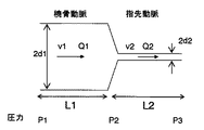
上腕部の血液循環状態を図9のようにモデル化する。
【0018】
ただし、図9においてv1、Q1,d1,L1は橈骨動脈での血流速度、血流量、血管半径、管の長さv2、Q2,d2,L2は指先の動脈での血流速度、血流量、血管半径、管の長さである。
【0019】
また、P1は橈骨動脈での血圧、P2は橈骨動脈と指先動脈の中間の部位での血圧、P3は指先動脈末端での血圧である。ここでP3は末梢での血圧値で数mmHgと小さいため、P1―P3が上腕での血圧値であると考えられる。すなわちこのP1−P3が測定したい血圧値となる。P1,P2,P3の関係は、ハーゲン−ポワズイユの法則から、ρを血液粘度として
P1−P2=(8ρL1Q1)/(πd1 4) ・・・(1)
P2−P3=(8ρL2Q2)/(πd2 4) ・・・(2)
という関係が成り立つ。なお、式1,2の右辺のうち、Q1,Q2が電気回路に置き換えた場合の電流に、また8ρL1/πd1 4、8ρL2/πd2 4が抵抗に該当する。8ρL1/πd1 4、8ρL2/πd2 4は血管の血管抵抗(末梢抵抗、粘性抵抗)に相当する。そのため、血圧は血流量と血管抵抗の積で表されることになる。
橈骨動脈での血圧値P1−P3は、式1,2から
P1−P3=(8ρL1Q1)/(πd1 4)+(8ρL2Q2/πd2 4)・(3)
一方血流量Q1,Q2は
Q1=(πd1 2v2)/8 ・・・・(4)
Q2=(πd2 2v2)/8 ・・・・(5)
という関係(生体計測とセンサ コロナ社 75項参照)があるため、式3は、
【0020】
また式6において、血管径d2の測定は指先の血管の径が細く、また血管が多数存在するため、測定が困難な場合が多い。そのため、d2をQ2とv2で置き換えることを考える。そのため、式5を変形して、
d2 2=8Q2/(πv2) ・・・・(7)
この式7を式6に代入すると、
【0021】
さらに、血流量Q1.Q2において、Q1=aQ2 a:定数と仮定すると、式4,5から
d1 2=av2d2 2/v1 ・・・・・(9)
この式9を式8に代入して、
【0022】
また、式6において、血管径d1、d2の変化が(脈拍ごとにおける血管径の最大値、最小値の変動が)それほど大きくないと仮定することも可能であり、この場合、生体内の2箇所の血流速度v1、v2によって血圧が概算できる。
以上をまとめると、
1、橈骨動脈の血管径と血流速度、指先の血管での血流速度と血管径
2、橈骨動脈の血管径と血流速度、指先の血管での血流速度と血流量
3、橈骨動脈の血流速度、指先の血管での血流速度と血流量
4、橈骨動脈の血流速度と指先の血管での血流速度
のいずれかによって血圧の測定が可能である。
【0023】
ただし、3に関してはQ1=aQ2という仮定が、4に関してはさらに血流量変化が大きくないという仮定が入っているため、装置自体は簡便なものとすることができるが、測定精度としてはやや落ちる。1,2に関しては測定する情報が多く、センサの保持構造、センサと血管との位置あわせ等を考慮しなければならないため、装置が大掛かりとなりやすい。
【0024】
そのため、使用形態、必要とされる測定精度、使用環境などを考慮していずれの方法を採用するか決定する必要がある。例えば、もっぱら室内での測定であり、環境温度が一定とみなせたり、激しい運動の前後などでは測定しないなどの条件を満たす場合には3,4などの簡便な方法によって血圧を測定し、それ以外の条件においては1,2などの基本的な方法によって血圧を測定するなどである。
【0025】
なお、本実施の形態では、橈骨動脈と指先の血管を対象としたが、一方が末梢部位(たとえば耳朶)で他方が比較的太い血管(頚動脈など)であれば上記関係とほぼ同じ関係が成立すると考えられるため、他の部位、血管での測定でも可能である。ただし、身体への装着性、測定の利便性を考慮すると、橈骨動脈と指先での測定が最適である。
【0026】
詳細な装置構成などについては以下の実施例で述べる。
【0027】
(実施例1)
本発明の血圧測定装置の一実施例について図1〜図5を用いて説明する。本実施例において本発明の血圧測定装置の基本構成を説明する。
【0028】
図1は、本発明の実施例にかかわる血圧測定装置の実施例の外観上の構成を示す図であり、図2は図1の指先測定部10の断面図、図3は手首測定部20の断面図、図4は信号処理部、図5は測定された血流速、光センサ出力から換算した血管径、血流量の波形を示す説明図である。
【0029】
図1に示すように、本実施例の血圧測定装置は、指先測定部10、手首測定部20、図示しない信号処理部50、図示しない出力部5658、ケーブル60から構成されている。
【0030】
図2は、図1上の指の長手方向(A−A‘)の断面図を図示したものである。
【0031】
図2に示すように、指先測定部10は指サック16の内側に血流速度センサ11,血流速度センサ12、光センサ13が存在する。光センサ13はLED14とフォトダイオード15によって構成される。
【0032】
血流速度センサ11,血流速度センサ12はそれぞれ所定の周波数の超音波を送受信する超音波センサである。超音波を血流に向けて照射すると、血流によって反射した超音波の周波数がドップラ効果を受けて変化する。この周波数の変化を検知することにより、血流速度を測定する。ここで、超音波センサと指先の血管との設置角度がずれると、測定される血流速度が変化するため、図2のように血流速度センサを二つ設けている。
【0033】
ドップラシフト周波数Δfは超音波送信角度と血管のなす角度θより次の式11を用いて血流速度を求めている。
【0034】
v=bΔf/2fcosθ (11)
ここで、bは生体内の音速、fは送信超音波の周波数である。
【0035】
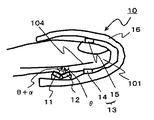
前記の方法で式11を用いて血流速度を求めるためには、動脈と波動のなす角θが既知である必要がある。しかしながら、動脈の位置が正確に把握できている場合は少ないので、図2に示すような複数個の血流速度センサを用いてθが未知な場合についても血流速度が求められるようなセンサを作製した。生体表面から内部に波動を送受信する血流速度センサ11,12を1対にした。この時、血流速度センサがそれぞれ受信するドップラシフト信号Δf及びΔf'、そして2個の血流速度センサのなす角をαとすると式12を用いてθを求めることができる。
【0036】
θ=tan-1(Δf'/Δf−cosα)/sinα (12)
そして、ここで求めたθとΔfを式11に代入することにより、血流速度vを求めることができる。また、ここで、血流速度センサを2個以上にし、θを数多く算出して平均をとる方法を用いても、θの測定精度が上がるのでさらに良い。
【0037】
なお、本実施例では血流速度センサ11,血流速度センサ12は、送信用、受信用に圧電素子(PZT)を1枚ずつ用いた連続式ドップラ血流センサを使用しており、制御する周波数としては9.6MHzの周波数を使用した。この場合、橈骨動脈を流れる血液に反射した超音波のドップラシフト周波数は最高で4K〜5KHzあり、血流速度は最高速度のピーク値で1.0m/s程度であった。
【0038】
次に、光センサ13について説明する。光センサ13はフォトダイオード15、LED14から構成される。
本実施例ではLED14によって照射された光が指先の毛細血管などを通過してきた光をフォトダイオード15によって検出する透過型の構成とした。
【0039】
ヘモグロビンの吸収係数が660nm付近で高くなるという吸光特性を利用するため、LED14の発光する波長は600〜850nmが適当である。
以上の血流速度センサ、光センサを指サック16内に配置して指先測定部10を構成する。
【0040】
次に手首測定部20の構成を説明する。
図3に示すように手首測定部20は血流速度センサ22、血流速度センサ23、光センサ24、リストバンド21で構成される。
【0041】
血流速度センサ22、血流速度センサ23は、指先測定部10の血流速度センサ11、血流速度センサ12と同じものを利用することもできるし、使用するPZTの形状、周波数を変更して使用することも可能である。指先にくらべ、橈骨動脈の血流速度は速く、また指先の血管より深い位置に血管が存在する。超音波の送信周波数と減衰率は比例関係にあり、超音波の送信周波数が高くなると生体内部で減衰する割合が大きくなる。一方、ドップラシフト周波数も送信周波数に比例する。
【0042】
そのため、超音波の減衰を抑えるため、血流によるドップラシフト周波数は低下するが、制御する周波数を指先の血流速度センサより低く設定することも有効であるが、本実施例では血流速度センサ11、12と同じ駆動周波数のセンサを使用した。
【0043】
光センサ24はLED26、フォトダイオード25から構成される。光センサについても、指先測定部10と同様の光センサを使用することもできるし、また使用する光の波長、強度を変更することも可能である。
【0044】
指先の血管は極めて多数存在し、その血管径を測定することは難しいが、後述するとおり、おおよその血流量の測定は比較的容易である。これに対して橈骨動脈へは光を正確に血管にあわせて照射する必要があるため、一般に指先よりも手首の橈骨動脈の測定の方が難しい。そのため、LED、フォトダイオードを複数個用いて、強度が最も大きいLED、フォトダイオードの組み合わせを利用することで、手首測定部のずれを補正することが有効となる。
【0045】
なお、LED26とフォトダイオード25の離間距離は測定できる生体内部の深さに比例し、広いほど深い部位の測定が可能となるが、受光される光の強度も低下してしまうため、最適な間隔とする必要があり、本実施例では5mmとした。
【0046】
以上の光センサ24、血流速度センサ22、23をリストバンド21内側に設けることで手首測定部20を構成している。
【0047】
指サック16,リストバンド21ともに、外乱光を遮断する保持の仕方などの構造を工夫すると、さらに測定精度を向上させることができる。
【0048】
次に本実施例の血圧計の信号処理部50について説明する。
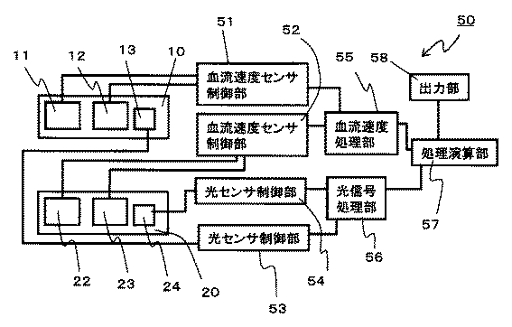
図4に示すように、信号処理部50は血流速度センサ制御部51,52,光センサ制御部53,54,血流速度処理部55,光信号処理部56、処理演算部57,出力部58とから構成される。
【0049】
血流速度センサ制御部51,52は血流速度センサ11,12,22,23の制御信号を送信し、その出力を受信する。そして血流速度処理部55によって出力が処理される。
【0050】
そして、血流速度処理部55によって指先、橈骨動脈の各血流速度が求められ、処理演算部57に処理された信号が送られる。
光センサ13,24は光センサ制御部53,54によって内部のLEDを発光しフォトダイオードによって受信された信号を出力する。受信信号は光信号処理部56によって処理される。
【0051】
光センサは、LEDによって発光した光が、血液にその強度の一部を吸収されフォトダイオードによって検出されることになる。そのため、LEDによって発光し、フォトダイオードによって検出される領域の血液量が多いほど受信信号(ここでは電圧値となる)は小さくなり、逆に血液量が少ないほど受信信号は大きくなる。
【0052】
この際、指先については毛細血管が極めて細いため、上記光の反射領域に毛細血管が無数に存在することになる。そのため、指先測定部10内の光センサ13の出力は複数の毛細血管を通過する血液量、すなわち血流量と同一視することができる。血流速度についても、複数の血管の血流速度を混合した形で検出されることになるが、(1)測定するのは複数の血管の血流速度分布であり、その最高流速あるいは平均流速を指先での血流速度とみなせばよいこと、(2)指先の血管それぞれにおいて、血流速度に大きな差がないとみなせること から血流速度に関しては、指先に血流速度センサを大まかにとりつけることで血流速度の測定が可能である。
【0053】
一方、手首測定部20内に設けられた光センサ24の場合、手首の橈骨動脈103の血管径は2〜3mm程度と大きく、上記光の反射領域には橈骨動脈103が大部分の割合を占めているものと見なせる。この場合、光センサ24の信号は、橈骨動脈103の径が大きいほど光の吸収が大きくなって信号強度が小さくなり、橈骨動脈103の径が小さいほど光の吸収が小さくなって信号強度が大きくなる。そのため、手首測定部20内に設けられた光センサ24によって橈骨動脈103の血管径変化を測定できることになる。
【0054】
このように血流速度処理部55,光信号処理部56によってそれぞれ橈骨動脈の血流速度v1,血管径d1、指先の血流速度v2、血流量Q2が求められ、処理演算部57によって式8を使用し、これらの情報から血圧を概算する。
【0055】
次に、実施例1の血圧測定方法について説明する。図5に手首の血流速度v1(図5(a)),手首の光信号出力の逆数(血管径d1と相似、図5(b))、指先の血流速度v2(図5(c))、指先の光信号出力の逆数(血流量Qと相似、図5(d))の脈拍拍動に伴う時間変化のグラフを示した。
【0056】
図5中のv1max、v2max、d1max、Q2maxのとき、式8によって求められる血圧が収縮期血圧であり、v1min、v2min、d1min、Q2minのとき、式8によって求められる血圧が拡張期血圧である。
【0057】
処理演算部57は式8に基づいて血圧変化を概算する。
なお、この場合血圧(拡張期、収縮期)の相対変化を概算することは可能であるが、血管径d1、血流量Q2ともに絶対値ではないこと、また式8内のL1,L2,ρが未定であることから、血圧の絶対値を求めることは出来ない。
【0058】
そのため、カフを使用して血圧の絶対値を測定できる血圧計によって一度血圧値を測定し、そのときの血流量、血流速度などを計測し、補正することで、血圧の絶対値を概算することが可能となる。
【0059】
通常の血圧計(コロトコフ法)と比較実験(日内変動を30分刻みで測定)を行った。血圧が収縮期で110〜130mmHg、拡張期で75〜90mmHgの範囲で変動したが、相関係数r2=0.7で良好な相関関係を得ることができた。式(10)をもとに補正係数を求め、実血圧値に換算したところ、実際の血圧値との最大誤差は5%以内(120mmHgで5mmHg以内)であり、十分な測定精度を得ることができた。また、運動時(自転車に20分乗った前後、及びクールダウン時)においても、相関係数r2=0.66と良好な関係が得られた。なお、通常の血圧計では、カフで加圧して止血する際の血圧値が測定されるのに対して、本発明の血圧測定装置においては脈拍ごとの血圧の測定ができる。
【0060】
血圧値は1拍1拍で異なる値を示すため、上記実験においては脈拍5拍分の平均値(拡張期、収縮期のそれぞれの状態における)から血圧を算出した。
【0061】
血流量Qが脈拍ごとにあまり変化せず、ほぼ一定と見なせるとすると、式10から、指先、手首の橈骨動脈の2カ所の血流速度を求めるだけで、血圧変動の測定が可能となる。
【0062】
この場合、上記のような運動を伴わない安静時の日内変動では良好な相関関係が得られが、運動など、血流量Qが増大する場合では相関関係がくずれ、r2=0.35となった。そのため、使用条件によって使用する関係式を使い分ける必要がある。
【0063】
なお、血圧測定装置の構成は、適宜変更することが可能であり、たとえば、血流速度センサをレーザドップラ方式のセンサに変更したり、フォトダイオードをフォトトランジスタに変更するなどの変更は当然可能である。
【0064】
また、指先の血流量の代わりに指先の血管の血管径を超音波エコー法などによって測定し、これから式6を使用して血圧を測定することも可能である。
【0065】
(実施例2)
本発明の血圧測定装置の一実施例について図6を用いて説明する。本実施例は、実施例1における手首測定部20の変形例を示す。
【0066】
図6は、図3の光センサ24の代わりに超音波を送受信することで橈骨動脈の血管径を測定する血管径センサ31を設けた実施例である。
【0067】
前述したとおり、血管径は光センサでも測定できるが、径を求めるためには、光センサのLEDの光照射範囲や、受光感度などをあらかじめ調べておく必要があり、センサごとの感度ばらつきなどを考慮すると、精度良く求めることは難しかった。一方、本実施例のような、超音波センサの場合、超音波の送信時間と受信時間の差を求めることで容易に血管径の測定が可能となる。そのため、本実施例の用に、超音波を利用した血管径センサを設けることで、血圧測定の制度を更に向上させることができる。
【0068】
(実施例3)
本発明の血圧測定装置の一実施例について図7を用いて説明する。本実施例は、実施例1における指先測定部10の変形例を示す。
【0069】
図7は、指先測定部10、手首測定部20(図示省略)を時計部40に設けた例である。指先測定部10に指先をあてて、時計のバンドに設けた図示しない手首測定部20によって血流速、血流量などの測定を行う。使用時には、手首に時計40のバンドを巻き付け、測定したいときに反対の手の人差し指(図7の例だと右手の)を測定部に押しあてることで測定が可能となる。
このような構成にすることで、手首測定部から指先測定部へよけいな配線などが不要となり、持ち運び、使用方法が容易となる。
【0070】
(実施例4)
本発明の血圧測定装置の一実施例について図8を用いて説明する。
本実施例は指先測定部10をマウス型の支持体に設けた例である。このように指先測定部10を据え置き型にすることで、指先測定部10がずれにくくなり、指先101と指先測定部10の接触状態を一定に保ちやすくなる。
指先測定部10と指先101の接触状態の再現性を向上させるため、指先測定部10の下部に圧力センサを設けて接触圧力を一定に保ったり、指先10との位置ずれを防止するため、指先測定部10の周囲をくぼませるなどをするとさらに測定精度を向上させることができる。
前述のような通常の血圧計との比較実験を行ったところ、相関係数r2=0.68と良好な相関を得ることができた。
【0071】
【発明の効果】
以上のように、本発明の血圧測定方法、及び血圧測定装置によれば、カフを使用せず、精度良く血圧を測定することができる。
【図面の簡単な説明】
【図1】実施例1に係る指先測定部、手首測定部を腕に装着した状態である。
【図2】図1における指先測定部のA―A‘ 断面である。
【図3】図1における手首測定部の断面図である。
【図4】実施例1に係る信号処理部の説明図である。
【図5】血流速度、光強度の変動を示した説明図である。
【図6】実施例2に係る手首測定部の変形例である。
【図7】実施例3に係る手首測定部、指先測定部の変形例である。
【図8】実施例3に係る手首測定部、指先測定部の変形例である。
【図9】上腕部のモデル図を示す。
【符号の説明】
10 指先測定部
20 手首測定部
11 血流速度センサ
12 血流速度センサ
13 光センサ
14 LED
15 フォトダイオード
16 指サック
21 リストバンド
22 血流速度センサ
23 血流速度センサ
24 光センサ
25 LED
26 フォトダイオード
31 血管径センサ
50 信号処理部
51、52 血流速度センサ制御部
53、54 光センサ制御部
55 血流速度処理部
56 光信号処理部
57 処理演算部
58 出力部
60 ケーブル
100 手
101 指先
102 手首
103 橈骨動脈
104 指先の血管
v1,v2 血流速度
d1,d2 血管径
V 血圧
Q,Q1,Q2 血流量
ρ 血液粘度
R1,R2 血管抵抗[0001]
TECHNICAL FIELD OF THE INVENTION
The present invention belongs to the technical field of a method for measuring blood pressure of a human body.
[0002]
[Prior art]
Today, a method of measuring blood pressure without using a cuff (compression band) has been proposed. This includes a pair of cardiac potential electrodes, a cardiac potential processing means for processing a cardiac potential signal from the cardiac potential electrode, a fingertip photoelectric pulse wave detection sensor, and a pulse wave processing means for processing the pulse wave signal. A second derivative processing means for further secondarily differentiating the processed pulse wave, and a processing means for calculating the blood pressure based on these processed cardiac potential signal, pulse wave signal, and second derivative signal of the pulse wave, Display means for displaying the calculation result, and the calculation means obtains a pulse wave transit time, a pulse wave interval, and a heart rate from the cardiac potential waveform and the pulse wave waveform, and the blood pressure is determined based on the pulse wave transit time, the pulse wave interval, and the heart rate. The calculation is performed (for example, see Patent Document 1).
[0003]
A pulse wave detecting means for detecting a pulse wave generated by blood circulation of a human body; and a characteristic amount calculating means for calculating at least one of a pulse wave propagation time and a pulse wave propagation speed from the detected pulse wave signal as a characteristic amount. And a blood pressure calculating means for calculating a blood pressure from the calculated characteristic amount (for example, see Patent Document 2).
[0004]
Furthermore, the actual blood pressure value actually measured from the pulse wave generated by the blood circulation, and the sensor value of the pulse wave detected from the pulse wave detecting means, each measured in a plurality of different blood pressure states, and calculated as a standard function, Hereinafter, a blood pressure measurement method characterized by calculating a blood pressure value by substituting a sensor value detected by a pulse wave detecting means into a standard function has been proposed. In some measurement in a plurality of different blood pressure states, measurement is performed by changing the detection site with respect to the heart in the vertical direction (for example, see Patent Document 3).
[0005]
[Patent Document 1]
JP-A-8-140948 (pages 2-3)
[0006]
[Patent Document 2]
JP-A-10-295657 (pages 2-3)
[0007]
[Patent Document 3]
JP 2001-275998 public information (page 2-3)
[0008]
[Problems to be solved by the invention]
However, as described later, the blood pressure is determined by the product of the blood flow and the vascular resistance. In any of the above blood pressure measurement methods, attention is paid only to one of the blood flow (information caused by the blood vessel diameter in Patent Document 3 and the like) and the peripheral resistance (a method using the pulse wave propagation speed and the pulse wave propagation time). However, under certain measurement conditions (constant temperature, constant time, etc.), a certain degree of correlation with the measured blood pressure value can be obtained, but blood flow significantly changes due to exercise, and peripheral vascular resistance is affected by stress, environment, etc. Since the blood pressure greatly changes depending on the temperature or the like, an accurate blood pressure value cannot be obtained by the conventional blood pressure measurement method.
[0009]
Therefore, a problem in the blood pressure measurement method and the blood pressure measurement device of the present invention is to estimate a blood pressure value using a change in peripheral resistance and blood flow, and to easily and noninvasively and accurately measure a blood pressure without using a cuff. It is to enable measurement.
[0010]
[Means for Solving the Problems]
Therefore, in order to solve the above problem, the blood pressure measurement device and the blood pressure measurement method of the present invention include at least two blood flow velocity measurement units that measure a blood flow velocity, and control the blood flow velocity measurement unit. The blood flow velocity is calculated from the information obtained from the blood flow velocity measurement control unit and the blood flow velocity measurement unit, and the blood flow velocity is measured at two different parts of the living body. The above object is achieved by a configuration for calculating blood pressure.
[0011]
In order to further improve blood pressure measurement accuracy, it has a blood vessel diameter measurement unit that measures the blood vessel diameter, and a blood vessel diameter measurement control unit that controls the blood vessel diameter measurement unit, and measures the blood flow velocity and the blood vessel diameter at two different locations. The object is achieved by calculating the blood pressure from the blood flow velocity and the blood vessel diameter at two locations.
[0012]
Also, in order to improve the measurement accuracy, a blood vessel diameter measuring unit for measuring a blood vessel diameter, a blood flow measuring unit for measuring a blood flow, a blood vessel diameter measuring control unit for controlling the blood vessel diameter measuring unit, and a blood flow for controlling the blood flow measuring unit. It has a measurement control unit, of two different parts, measures the blood flow velocity and blood vessel diameter in one blood vessel and the blood flow velocity and blood flow in the other blood vessel, and measures the blood flow velocity, blood vessel diameter and blood flow. The above object is achieved by a configuration for calculating blood pressure.
[0013]
In addition, it has a blood flow measurement unit that transmits and receives waves from the inside of the living body to the inside of the living body and measures the blood flow, and a blood flow measurement control unit that controls the blood flow measurement unit. If the blood flow velocity and the blood flow are measured in the other blood vessel, and the blood pressure is calculated from the blood flow velocity and the blood flow by the processing unit, the measurement accuracy can be further improved.
[0014]
The two different portions are one of which is a radial artery, the other is a blood vessel of a fingertip, a blood flow velocity sensor and a volume pulse wave sensor, a blood flow velocity sensor control unit for controlling the blood flow velocity sensor, and the volume pulse. A volume pulse wave sensor control unit for controlling a wave sensor, the blood flow velocity sensor, a processing unit for processing a signal from the volume pulse wave sensor, the blood flow velocity sensor near the radial artery and around the blood vessel at the fingertip, A configuration in which a plethysmogram sensor is provided may be employed.
[0015]
Further, the systolic blood pressure and the diastolic blood pressure are measured using a conventional sphygmomanometer using a cuff, and the systolic blood pressure and the diastolic blood pressure are measured from the blood flow velocity, the blood vessel diameter, and the like at the same time as the measurement. The correction coefficient for calculating the actual systolic blood pressure from the systolic blood pressure, and the correction coefficient for calculating the diastolic actual blood pressure from the diastolic blood pressure, respectively, and thereafter, without using a sphygmomanometer using the cuff, the blood flow When the measurement is performed using the speed and the blood vessel diameter, the actual systolic blood pressure is obtained using the systolic blood pressure and the correction coefficient, and the diastolic actual blood pressure is calculated using the diastolic blood pressure and the correction coefficient. Blood pressure values can also be determined.
[0016]
Details will be described in the following embodiments of the invention.
[0017]
BEST MODE FOR CARRYING OUT THE INVENTION
The blood circulation state of the upper arm is modeled as shown in FIG.
[0018]
However, in FIG. 9, v1, Q1, d1, and L1 represent the blood flow velocity and blood flow in the radial artery, the blood vessel radius, and the length of the tube v2, and Q2, d2, and L2 represent the blood flow velocity and the blood flow in the fingertip artery. , Radius of blood vessel, length of tube.
[0019]
P1 is the blood pressure in the radial artery, P2 is the blood pressure in the middle part between the radial artery and the fingertip artery, and P3 is the blood pressure in the distal end of the fingertip artery. Here, since P3 is a small peripheral blood pressure value of several mmHg, P1-P3 is considered to be the upper arm blood pressure value. That is, P1-P3 is the blood pressure value to be measured. P1, P2, the relationship P3 is Hagen - from the law of Poiseuille, P 1 and ρ as blood viscosity -P 2 = (8ρL 1 Q 1 ) / (πd 1 4) ··· (1)
P 2 -P 3 = (8ρL 2 Q 2) / (πd 2 4) ··· (2)
The relationship holds. Of the right side of expression 1, 2, Q1, Q2 is the current in the case of replacing the electric circuit, also 8ρL 1 / πd 1 4, 8ρL 2 / πd 2 4 corresponds to the resistance. 8ρL 1 / πd 1 4, 8ρL 2 / πd 2 4 corresponds to vascular resistance of blood vessels (peripheral resistance, viscous resistance). Therefore, blood pressure is represented by the product of blood flow and vascular resistance.
Blood pressure value P1-P3 at radial artery, P 1 -P formulas 1,2 3 = (8ρL 1 Q 1 ) / (πd 1 4) + (8ρL 2 Q 2 / πd 2 4) · (3)
On the other hand, the blood flow rates Q1 and Q2 are Q 1 = (πd 1 2 v 2 ) / 8 (4)
Q 2 = (πd 2 2 v 2 ) / 8 (5)
Equation (3) (Equipment 3)
[0020]
In Equation 6, the measurement of the blood vessel diameter d2 is often difficult because the diameter of the blood vessel at the fingertip is small and there are many blood vessels. Therefore, consider replacing d2 with Q2 and v2. Therefore, by transforming Equation 5,
d 2 2 = 8Q 2 / ( πv 2) ···· (7)
By substituting
[0021]
Further, the blood flow Q1. In Q2, Q1 = aQ2 a: Assuming a constant, from equation 4,5 d 1 2 = av 2 d 2 2 / v 1 ····· (9)
Substituting Equation 9 into Equation 8,
[0022]
Further, in Equation 6, it is also possible to assume that changes in the blood vessel diameters d 1 and d 2 are not so large (fluctuations in the maximum value and the minimum value of the blood vessel diameter for each pulse). The blood pressure can be roughly estimated from the two blood flow velocities v 1 and v 2 .
To summarize the above,
1. Blood vessel diameter and blood flow velocity in radial artery, blood flow velocity and blood diameter in blood vessel at fingertip 2, blood vessel diameter and blood flow velocity in radial artery, blood flow velocity and blood flow in blood vessel at fingertip 3, radial artery The blood pressure can be measured by any one of the blood flow velocity of the fingertip, the blood flow velocity and blood flow in the fingertip blood vessel 4, and the blood flow velocity of the radial artery and the blood flow velocity in the fingertip blood vessel.
[0023]
However, since the assumption of Q1 = aQ2 for 3 and the assumption that the change in blood flow is not large for 4 are included, the apparatus itself can be simplified, but the measurement accuracy is slightly reduced. Since there is much information to be measured for 1 and 2, and the sensor holding structure, the alignment between the sensor and the blood vessel, and the like must be taken into account, the apparatus tends to be large-scale.
[0024]
Therefore, it is necessary to determine which method is to be used in consideration of the usage form, required measurement accuracy, usage environment, and the like. For example, when measuring only indoors, if the environmental temperature can be regarded as constant, or if conditions such as not measuring before and after strenuous exercise are met, blood pressure is measured by a simple method such as 3 or 4, and otherwise Under these conditions, blood pressure is measured by a basic method such as 1 or 2.
[0025]
In the present embodiment, the radial artery and the blood vessel at the fingertip are targeted. However, if one is a peripheral part (for example, an earlobe) and the other is a relatively thick blood vessel (such as a carotid artery), the above relation is almost the same. Therefore, it is also possible to measure at other sites and blood vessels. However, in consideration of the wearability to the body and the convenience of the measurement, the measurement with the radial artery and the fingertip is optimal.
[0026]
Detailed device configuration and the like will be described in the following embodiments.
[0027]
(Example 1)
One embodiment of the blood pressure measurement device of the present invention will be described with reference to FIGS. In this embodiment, the basic configuration of the blood pressure measurement device of the present invention will be described.
[0028]
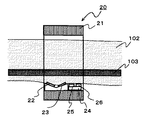
FIG. 1 is a diagram showing an external configuration of an embodiment of a blood pressure measurement device according to an embodiment of the present invention. FIG. 2 is a cross-sectional view of a
[0029]
As shown in FIG. 1, the blood pressure measurement device of the present embodiment includes a
[0030]
FIG. 2 is a cross-sectional view of the finger in FIG. 1 in the longitudinal direction (AA ′).
[0031]
As shown in FIG. 2, the
[0032]
The blood
[0033]
The Doppler shift frequency Δf determines the blood flow velocity from the ultrasonic transmission angle and the angle θ formed by the blood vessel using the following
[0034]
v = bΔf / 2fcosθ (11)
Here, b is the speed of sound in the living body, and f is the frequency of the transmitted ultrasonic wave.
[0035]
In order to obtain the blood flow velocity by using the
[0036]
θ = tan-1 (Δf ′ / Δf−cosα) / sinα (12)
Then, the blood flow velocity v can be obtained by substituting θ and Δf obtained here into
[0037]
In this embodiment, the blood
[0038]
Next, the
In the present embodiment, a transmission type configuration is used in which light emitted by the
[0039]
The wavelength of light emitted by the
The
[0040]
Next, the configuration of the
As shown in FIG. 3, the
[0041]
The blood
[0042]
Therefore, the Doppler shift frequency due to the blood flow is reduced in order to suppress the attenuation of the ultrasonic wave, but it is also effective to set the frequency to be controlled lower than the blood flow velocity sensor at the fingertip. Sensors having the same driving frequency as 11 and 12 were used.
[0043]
The
[0044]
There are a large number of blood vessels at the fingertip, and it is difficult to measure the diameter of the blood vessels. However, as will be described later, the measurement of the approximate blood flow is relatively easy. On the other hand, it is generally more difficult to measure the radial artery at the wrist than at the fingertip because it is necessary to irradiate the light to the blood vessel accurately to the radial artery. Therefore, it is effective to correct the displacement of the wrist measurement unit by using a plurality of LEDs and photodiodes and using the combination of the LED and photodiode having the highest intensity.
[0045]
Note that the distance between the
[0046]
The
[0047]
If both the
[0048]
Next, the
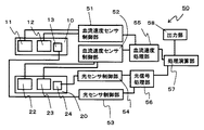
As shown in FIG. 4, the
[0049]
The blood flow velocity
[0050]
Then, the blood flow
The
[0051]
In the light sensor, the light emitted by the LED is partially absorbed by blood and detected by the photodiode. Therefore, the received signal (in this case, the voltage value) becomes smaller as the blood volume in the region emitted by the LED and detected by the photodiode becomes larger, and conversely, the received signal becomes larger as the blood volume becomes smaller.
[0052]
At this time, since the capillaries of the fingertip are extremely thin, there are countless capillaries in the light reflection area. Therefore, the output of the
[0053]
On the other hand, in the case of the
[0054]
As described above, the blood flow velocity v1, the blood vessel diameter d1, the finger blood flow velocity v2, and the blood flow Q2 are obtained by the blood flow
[0055]
Next, a blood pressure measurement method according to the first embodiment will be described. FIG. 5 shows the blood flow velocity v1 of the wrist (FIG. 5 (a)), the reciprocal of the optical signal output of the wrist (similar to the blood vessel diameter d1, FIG. 5 (b)), and the blood flow velocity v2 of the fingertip (FIG. 5 (c)). 5), and the reciprocal of the optical signal output of the fingertip (similar to the blood flow Q, FIG. 5D) is a graph showing the time change with the pulsation.
[0056]
5 in v 1max, v 2max, d 1max , when Q 2max, blood pressure is determined by equation 8 is systolic blood pressure, v 1min, v 2min, d 1min, when Q 2min, given by Equation 8 Blood pressure is diastolic blood pressure.
[0057]
The
In this case, it is possible to roughly estimate the relative change in the blood pressure (diastole, systole), but neither the blood vessel diameter d1 nor the blood flow Q2 are absolute values. Since it is undecided, the absolute value of the blood pressure cannot be obtained.
[0058]
Therefore, the blood pressure is measured once by a sphygmomanometer that can measure the absolute value of blood pressure using a cuff, and the blood flow rate, blood flow velocity, etc. at that time are measured and corrected, and the absolute value of the blood pressure is roughly estimated. It becomes possible.
[0059]
Comparative experiments (measured daily fluctuations every 30 minutes) were performed with a normal blood pressure monitor (Korotkov method). Although the blood pressure fluctuated in the range of 110 to 130 mmHg in the systole and 75 to 90 mmHg in the diastole, a good correlation could be obtained with a correlation coefficient r 2 = 0.7. When a correction coefficient was obtained based on the equation (10) and converted into an actual blood pressure value, the maximum error from the actual blood pressure value was within 5% (within 5 mmHg at 120 mmHg), and sufficient measurement accuracy could be obtained. did it. Also during exercise (before and after riding the bicycle for 20 minutes and during cool down), a good correlation was obtained with a correlation coefficient r 2 = 0.66. It should be noted that while a normal sphygmomanometer measures a blood pressure value when stopping blood by pressurizing with a cuff, the blood pressure measurement device of the present invention can measure a blood pressure for each pulse.
[0060]
Since the blood pressure value shows different values for each pulse, in the above experiment, the blood pressure was calculated from the average value of the five pulses (in each state of diastole and systole).
[0061]
Assuming that the blood flow Q does not change much for each pulse and can be regarded as substantially constant, it is possible to measure the blood pressure fluctuation only by obtaining the blood flow velocity at the two places of the finger art and the radial artery of the wrist from
[0062]
In this case, a good correlation is obtained in the above-mentioned circadian variation at rest without exercise, but when the blood flow Q increases, such as in exercise, the correlation is broken, and r 2 = 0.35. Was. Therefore, it is necessary to properly use the relational expression to be used depending on the use condition.
[0063]
The configuration of the blood pressure measurement device can be changed as appropriate. For example, it is naturally possible to change the blood flow velocity sensor to a laser Doppler sensor or change the photodiode to a phototransistor. is there.
[0064]
Alternatively, the blood vessel diameter of the blood vessel at the fingertip may be measured by an ultrasonic echo method or the like instead of the blood flow volume at the fingertip, and the blood pressure may be measured using Expression 6 from this.
[0065]
(Example 2)
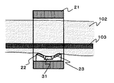
One embodiment of the blood pressure measurement device of the present invention will be described with reference to FIG. This embodiment shows a modification of the
[0066]
FIG. 6 shows an embodiment in which a blood
[0067]
As described above, the blood vessel diameter can also be measured with an optical sensor, but in order to determine the diameter, it is necessary to check the light irradiation range of the LED of the optical sensor, the light receiving sensitivity, etc. in advance. Considering this, it was difficult to determine the accuracy. On the other hand, in the case of the ultrasonic sensor as in the present embodiment, it is possible to easily measure the blood vessel diameter by obtaining the difference between the transmission time and the reception time of the ultrasonic wave. Therefore, by providing a blood vessel diameter sensor using ultrasonic waves for the present embodiment, the accuracy of blood pressure measurement can be further improved.
[0068]
(Example 3)
One embodiment of the blood pressure measurement device of the present invention will be described with reference to FIG. This embodiment shows a modification of the
[0069]
FIG. 7 shows an example in which a
With such a configuration, extra wiring or the like from the wrist measuring unit to the fingertip measuring unit is not required, and the portable device can be easily carried and used.
[0070]
(Example 4)
One embodiment of the blood pressure measurement device of the present invention will be described with reference to FIG.
This embodiment is an example in which the
In order to improve the reproducibility of the contact state between the
As a result of a comparative experiment with a normal blood pressure monitor as described above, a good correlation was obtained with a correlation coefficient r 2 = 0.68.
[0071]
【The invention's effect】
As described above, according to the blood pressure measurement method and the blood pressure measurement device of the present invention, blood pressure can be accurately measured without using a cuff.
[Brief description of the drawings]
FIG. 1 illustrates a state in which a fingertip measurement unit and a wrist measurement unit according to a first embodiment are mounted on an arm.
FIG. 2 is a sectional view taken along the line AA ′ of the fingertip measuring unit in FIG. 1;
FIG. 3 is a cross-sectional view of a wrist measuring unit in FIG.
FIG. 4 is an explanatory diagram of a signal processing unit according to the first embodiment.
FIG. 5 is an explanatory diagram showing changes in blood flow velocity and light intensity.
FIG. 6 is a modified example of the wrist measuring unit according to the second embodiment.
FIG. 7 is a modified example of the wrist measurement unit and the fingertip measurement unit according to the third embodiment.
FIG. 8 is a modification example of the wrist measurement unit and the fingertip measurement unit according to the third embodiment.
FIG. 9 shows a model diagram of an upper arm.
[Explanation of symbols]
15
26
Claims (16)
前記血流速度測定部を制御する血流速度測定制御部と、
前記血流速度測定部で測定された血流速度から、生体の血圧を算出する演算部と、から構成される血圧測定装置。Measuring blood flow velocity at two or more parts of the living body, at least two or more blood flow velocity measurement unit,
A blood flow velocity measurement control unit that controls the blood flow velocity measurement unit,
A blood pressure measurement device comprising: a calculation unit configured to calculate a blood pressure of a living body from the blood flow velocity measured by the blood flow velocity measurement unit.
前記血管径測定部を制御する血管径測定制御部と、を有し、
前記血管径測定部で測定された血管径と前記血流速度測定部で測定された血流速度から、前記演算部によって生体の血圧を算出することを特徴とする請求項1記載の血圧測定装置。A blood vessel diameter measuring unit for measuring a blood vessel diameter of a living body,
A blood vessel diameter measurement control unit that controls the blood vessel diameter measurement unit,
The blood pressure measurement device according to claim 1, wherein the blood pressure of the living body is calculated by the calculation unit from the blood vessel diameter measured by the blood vessel diameter measurement unit and the blood flow velocity measured by the blood flow velocity measurement unit. .
前記血管径測定部を制御する血管径測定制御部と、
生体の血流量を測定する血流量測定部と、
前記血流量測定部を制御する血流量測定制御部と、を有し、
生体の二箇所の部位において、一方の部位では血流速度と血管径を測定し、他方の部位では血流速度と血流量を測定し、前記演算部においてこれらの測定結果から生体の血圧を算出することを特徴とする請求項1記載の血圧測定装置。A blood vessel diameter measuring unit for measuring a blood vessel diameter of a living body,
A blood vessel diameter measurement control unit that controls the blood vessel diameter measurement unit,
A blood flow measurement unit that measures the blood flow of the living body,
A blood flow measurement control unit that controls the blood flow measurement unit,
In two parts of a living body, one part measures a blood flow velocity and a blood vessel diameter, and the other part measures a blood flow velocity and a blood flow, and calculates the blood pressure of the living body from these measurement results in the arithmetic unit. The blood pressure measurement device according to claim 1, wherein the measurement is performed.
前記血流量測定部を制御する血流量測定制御部と、を有し、
生体の二箇所の部位において、一方の部位では血流速度と血流量を測定し、他方の部位では血流速度を測定し、前記演算部によってこれらの測定結果から生体の血圧を算出することを特徴とする請求項1記載の血圧測定装置。A blood flow measurement unit that measures the blood flow of the living body,
A blood flow measurement control unit that controls the blood flow measurement unit,
In two parts of the living body, one part measures the blood flow velocity and the blood flow rate, the other part measures the blood flow velocity, and calculates the blood pressure of the living body from these measurement results by the arithmetic unit. The blood pressure measurement device according to claim 1, wherein
前記血流センサを制御する血流センサ制御部と、
生体の脈波を測定する容積脈波センサと、
前記容積脈波センサを制御する容積脈波センサ制御部と、
前記血流速度センサ及び前記容積脈波センサからの信号を処理する信号処理部と、を有し、
生体の動脈付近で血流速度を測定し、指先の末梢血管周辺で血流速度と脈波を測定し、これらの測定結果から生体の血圧を算出することを特徴とする血圧測定装置。A blood flow velocity sensor for measuring a blood flow velocity of a living body,
A blood flow sensor control unit that controls the blood flow sensor,
A volume pulse wave sensor for measuring a pulse wave of a living body,
A volume pulse wave sensor control unit that controls the volume pulse wave sensor,
A signal processing unit that processes signals from the blood flow velocity sensor and the volume pulse wave sensor,
A blood pressure measurement device that measures a blood flow velocity near an artery of a living body, measures a blood flow velocity and a pulse wave around a peripheral blood vessel at a fingertip, and calculates a blood pressure of the living body from the measurement results.
前記血流センサを制御する血流速度センサ制御部と、
生体の脈波を測定する容積脈波センサと、
前記容積脈波センサを制御する容積脈波センサ制御部と、
前記血流速度センサ及び前記容積脈波センサからの信号を処理する信号処理部と、を有し、
生体の動脈付近と指先の末梢血管周辺で血流速度と脈波を測定し、これらの測定結果から生体の血圧を算出することを特徴とする血圧測定装置。A blood flow velocity sensor for measuring a blood flow velocity of a living body,
A blood flow velocity sensor control unit that controls the blood flow sensor,
A volume pulse wave sensor for measuring a pulse wave of a living body,
A volume pulse wave sensor control unit that controls the volume pulse wave sensor,
A signal processing unit that processes signals from the blood flow velocity sensor and the volume pulse wave sensor,
A blood pressure measuring device that measures a blood flow velocity and a pulse wave near an artery of a living body and around a peripheral blood vessel at a fingertip, and calculates a blood pressure of the living body from the measurement results.
以降は前記血流速度、前記血管径、あるいは前記血流量を測定し、前記血流速度と前記血管径、前記血流量及び前記補正係数を用いて収縮期実血圧と拡張期実血圧を算出することを特徴とする血圧測定方法。In the blood pressure measurement method according to any one of claims 8 to 13, the systolic real blood pressure and the diastolic real blood pressure are measured by a conventional sphygmomanometer using a cuff, and at the same time as the measurement, the blood flow velocity, The blood vessel diameter, or measure the blood flow, the blood flow velocity, the blood vessel diameter, a correction coefficient for calculating the systolic actual blood pressure from the blood flow, and a correction coefficient for calculating the diastolic actual blood pressure, respectively.
Thereafter, the blood flow velocity, the blood vessel diameter, or the blood flow is measured, and the systolic blood pressure and the diastolic blood pressure are calculated using the blood flow velocity and the blood vessel diameter, the blood flow, and the correction coefficient. A method for measuring blood pressure, characterized in that:
Priority Applications (1)
| Application Number | Priority Date | Filing Date | Title |
|---|---|---|---|
| JP2002373433A JP3908660B2 (en) | 2002-12-25 | 2002-12-25 | Blood pressure measurement device |
Applications Claiming Priority (1)
| Application Number | Priority Date | Filing Date | Title |
|---|---|---|---|
| JP2002373433A JP3908660B2 (en) | 2002-12-25 | 2002-12-25 | Blood pressure measurement device |
Publications (2)
| Publication Number | Publication Date |
|---|---|
| JP2004201868A true JP2004201868A (en) | 2004-07-22 |
| JP3908660B2 JP3908660B2 (en) | 2007-04-25 |
Family
ID=32811712
Family Applications (1)
| Application Number | Title | Priority Date | Filing Date |
|---|---|---|---|
| JP2002373433A Expired - Fee Related JP3908660B2 (en) | 2002-12-25 | 2002-12-25 | Blood pressure measurement device |
Country Status (1)
| Country | Link |
|---|---|
| JP (1) | JP3908660B2 (en) |
Cited By (18)
| Publication number | Priority date | Publication date | Assignee | Title |
|---|---|---|---|---|
| JP2006102250A (en) * | 2004-10-06 | 2006-04-20 | Terumo Corp | Circulation index measurement device, circulation index measurement method, control program, and computer-readable storage medium |
| JP2006204722A (en) * | 2005-01-31 | 2006-08-10 | Seiko Instruments Inc | Blood viscosity measuring device |
| JP2006204432A (en) * | 2005-01-26 | 2006-08-10 | Seiko Instruments Inc | Biological information measuring device |
| JP2008114037A (en) * | 2006-10-12 | 2008-05-22 | Nippon Telegr & Teleph Corp <Ntt> | Blood pressure measuring device and blood pressure measuring device control method |
| JP2008536545A (en) * | 2005-03-21 | 2008-09-11 | ヘルス−スマート リミテッド | System for continuous blood pressure monitoring |
| JP2009153832A (en) * | 2007-12-27 | 2009-07-16 | Toshiba Corp | Pulse wave measuring device |
| KR101038434B1 (en) * | 2009-07-31 | 2011-06-01 | 주식회사 바이오넷 | Heart rate systolic blood pressure measurement device using belt type ECG and band type pulse wave measuring device |
| JP2012061131A (en) * | 2010-09-16 | 2012-03-29 | Seiko Epson Corp | Fluid pressure measuring apparatus, fluid pressure measuring method, blood pressure measuring apparatus, and blood pressure measuring method |
| JP2012065747A (en) * | 2010-09-22 | 2012-04-05 | Seiko Epson Corp | Device and method for measuring fluid pulsation pressure, and device and method for measuring pulse pressure |
| JP2012223375A (en) * | 2011-04-20 | 2012-11-15 | Seiko Epson Corp | Ultrasonic measuring apparatus and ultrasonic measuring method |
| WO2014102860A1 (en) * | 2012-12-26 | 2014-07-03 | テルモ株式会社 | Peripheral vascular resistance measurement device and method for controlling the same |
| CN104523260A (en) * | 2014-12-08 | 2015-04-22 | 北京工业大学 | Microcirculatory blood flow velocity measuring device and method |
| EP3033990A1 (en) | 2014-12-17 | 2016-06-22 | Seiko Epson Corporation | Blood pressure measurement device, electronic device, and blood pressure measurement method |
| WO2016126445A1 (en) * | 2015-02-02 | 2016-08-11 | Midmark Corporation | System and method for non-invasive blood pressure measurement |
| JP2019033902A (en) * | 2017-08-16 | 2019-03-07 | セイコーエプソン株式会社 | Biological analysis apparatus, biological analysis method, and program |
| JP2019208616A (en) * | 2018-05-31 | 2019-12-12 | セイコーエプソン株式会社 | Organism analyzer, organism analysis method and program |
| CN112367913A (en) * | 2018-07-18 | 2021-02-12 | 索尼公司 | Measuring device and measuring method |
| CN114587309A (en) * | 2022-03-16 | 2022-06-07 | 皖南医学院第一附属医院(皖南医学院弋矶山医院) | Blood pressure measurement method and system |
-
2002
- 2002-12-25 JP JP2002373433A patent/JP3908660B2/en not_active Expired - Fee Related
Cited By (27)
| Publication number | Priority date | Publication date | Assignee | Title |
|---|---|---|---|---|
| JP2006102250A (en) * | 2004-10-06 | 2006-04-20 | Terumo Corp | Circulation index measurement device, circulation index measurement method, control program, and computer-readable storage medium |
| JP2006204432A (en) * | 2005-01-26 | 2006-08-10 | Seiko Instruments Inc | Biological information measuring device |
| JP2006204722A (en) * | 2005-01-31 | 2006-08-10 | Seiko Instruments Inc | Blood viscosity measuring device |
| JP2008536545A (en) * | 2005-03-21 | 2008-09-11 | ヘルス−スマート リミテッド | System for continuous blood pressure monitoring |
| JP2008114037A (en) * | 2006-10-12 | 2008-05-22 | Nippon Telegr & Teleph Corp <Ntt> | Blood pressure measuring device and blood pressure measuring device control method |
| JP2009153832A (en) * | 2007-12-27 | 2009-07-16 | Toshiba Corp | Pulse wave measuring device |
| US8920331B2 (en) | 2007-12-27 | 2014-12-30 | Kabushiki Kaisha Toshiba | Pulse wave measuring device |
| KR101038434B1 (en) * | 2009-07-31 | 2011-06-01 | 주식회사 바이오넷 | Heart rate systolic blood pressure measurement device using belt type ECG and band type pulse wave measuring device |
| JP2012061131A (en) * | 2010-09-16 | 2012-03-29 | Seiko Epson Corp | Fluid pressure measuring apparatus, fluid pressure measuring method, blood pressure measuring apparatus, and blood pressure measuring method |
| JP2012065747A (en) * | 2010-09-22 | 2012-04-05 | Seiko Epson Corp | Device and method for measuring fluid pulsation pressure, and device and method for measuring pulse pressure |
| JP2012223375A (en) * | 2011-04-20 | 2012-11-15 | Seiko Epson Corp | Ultrasonic measuring apparatus and ultrasonic measuring method |
| JPWO2014102860A1 (en) * | 2012-12-26 | 2017-01-12 | テルモ株式会社 | Peripheral vascular resistance measuring device and control method thereof |
| WO2014102860A1 (en) * | 2012-12-26 | 2014-07-03 | テルモ株式会社 | Peripheral vascular resistance measurement device and method for controlling the same |
| CN104822315A (en) * | 2012-12-26 | 2015-08-05 | 泰尔茂株式会社 | Peripheral blood vessel resistance measuring device and control method thereof |
| US10159414B2 (en) | 2012-12-26 | 2018-12-25 | Terumo Kabushiki Kaisha | Peripheral vascular resistance measuring device and method for controlling the same |
| CN104822315B (en) * | 2012-12-26 | 2017-05-03 | 泰尔茂株式会社 | Peripheral vascular resistance measurement device and method for controlling same |
| CN104523260A (en) * | 2014-12-08 | 2015-04-22 | 北京工业大学 | Microcirculatory blood flow velocity measuring device and method |
| US9737218B2 (en) | 2014-12-17 | 2017-08-22 | Seiko Epson Corporation | Blood pressure measurement device, electronic device, and blood pressure measurement method |
| EP3033990A1 (en) | 2014-12-17 | 2016-06-22 | Seiko Epson Corporation | Blood pressure measurement device, electronic device, and blood pressure measurement method |
| WO2016126445A1 (en) * | 2015-02-02 | 2016-08-11 | Midmark Corporation | System and method for non-invasive blood pressure measurement |
| JP2019033902A (en) * | 2017-08-16 | 2019-03-07 | セイコーエプソン株式会社 | Biological analysis apparatus, biological analysis method, and program |
| JP7069598B2 (en) | 2017-08-16 | 2022-05-18 | セイコーエプソン株式会社 | Bioanalyzers, bioanalysis methods and programs |
| JP2019208616A (en) * | 2018-05-31 | 2019-12-12 | セイコーエプソン株式会社 | Organism analyzer, organism analysis method and program |
| JP7187824B2 (en) | 2018-05-31 | 2022-12-13 | セイコーエプソン株式会社 | Biological analysis device, biological analysis method and program |
| CN112367913A (en) * | 2018-07-18 | 2021-02-12 | 索尼公司 | Measuring device and measuring method |
| CN114587309A (en) * | 2022-03-16 | 2022-06-07 | 皖南医学院第一附属医院(皖南医学院弋矶山医院) | Blood pressure measurement method and system |
| CN114587309B (en) * | 2022-03-16 | 2024-03-01 | 皖南医学院第一附属医院(皖南医学院弋矶山医院) | Blood pressure measurement method and system |
Also Published As
| Publication number | Publication date |
|---|---|
| JP3908660B2 (en) | 2007-04-25 |
Similar Documents
| Publication | Publication Date | Title |
|---|---|---|
| JP3908660B2 (en) | Blood pressure measurement device | |
| EP2291111B1 (en) | Contactless respiration monitoring of a patient and optical sensor for a photoplethysmography measurement | |
| JP3910521B2 (en) | Blood pressure measurement device | |
| EP2462864B1 (en) | Optical vital sign detection method and measurement device | |
| US7179228B2 (en) | Cuffless system for measuring blood pressure | |
| US8277388B2 (en) | Blood rheology measuring apparatus | |
| JP2011239972A (en) | Blood pressure measuring device and method | |
| US20080071180A1 (en) | Vital Sign Detection Method and Measurement Device | |
| WO2012101951A1 (en) | Blood vessel pulse-wave measuring system | |
| JP2002360530A (en) | Pulse wave sensor and pulse rate detector | |
| JP2006239114A (en) | Cuff-less electronic blood pressure monitor | |
| US20250072836A1 (en) | Pulse wave signal processor, physiological information measurement device, and contact-pressure abnormality determination method | |
| JP2011167424A (en) | Blood pressure monitoring apparatus | |
| JP5552982B2 (en) | Pulse pressure measuring device and pulse pressure measuring method | |
| KR20100048359A (en) | Ultrasound system for providing ultrasound image with additional information | |
| CN112512416A (en) | Device and method for automatic identification of Korotkoff sounds and/or bioacoustic signals using an optical stethoscope | |
| KR20200129811A (en) | Blood Pressure Meter And Method For Measuring Blood Pressure Using The Same | |
| KR102214774B1 (en) | Cardiovascular and Cerebrovascular Disease Risk Assessment System Using Adsorption Cup Type Blood Flow Measurement Sensor | |
| JP2002320593A (en) | Method and apparatus for measuring arterial blood pressure | |
| JP5552984B2 (en) | Pulse pressure measuring device and pulse pressure measuring method | |
| JP4502537B2 (en) | Bath sphygmomanometer | |
| JP2018130227A (en) | Vascular pulse wave measurement system | |
| JP2003260032A (en) | Pulse wave measuring apparatus and bathtub hemomanometer having the same | |
| JP2007075482A (en) | Pulse rate measuring instrument | |
| JP2005021347A (en) | Blood pressure monitor and blood pressure measurement method |
Legal Events
| Date | Code | Title | Description |
|---|---|---|---|
| A621 | Written request for application examination |
Free format text: JAPANESE INTERMEDIATE CODE: A621 Effective date: 20050913 |
|
| A977 | Report on retrieval |
Free format text: JAPANESE INTERMEDIATE CODE: A971007 Effective date: 20061023 |
|
| A131 | Notification of reasons for refusal |
Free format text: JAPANESE INTERMEDIATE CODE: A131 Effective date: 20061031 |
|
| A521 | Written amendment |
Free format text: JAPANESE INTERMEDIATE CODE: A523 Effective date: 20061212 |
|
| TRDD | Decision of grant or rejection written | ||
| A01 | Written decision to grant a patent or to grant a registration (utility model) |
Free format text: JAPANESE INTERMEDIATE CODE: A01 Effective date: 20070116 |
|
| A61 | First payment of annual fees (during grant procedure) |
Free format text: JAPANESE INTERMEDIATE CODE: A61 Effective date: 20070118 |
|
| R150 | Certificate of patent or registration of utility model |
Ref document number: 3908660 Country of ref document: JP Free format text: JAPANESE INTERMEDIATE CODE: R150 Free format text: JAPANESE INTERMEDIATE CODE: R150 |
|
| RD01 | Notification of change of attorney |
Free format text: JAPANESE INTERMEDIATE CODE: A7421 Effective date: 20091108 |
|
| FPAY | Renewal fee payment (event date is renewal date of database) |
Free format text: PAYMENT UNTIL: 20110126 Year of fee payment: 4 |
|
| FPAY | Renewal fee payment (event date is renewal date of database) |
Free format text: PAYMENT UNTIL: 20110126 Year of fee payment: 4 |
|
| RD03 | Notification of appointment of power of attorney |
Free format text: JAPANESE INTERMEDIATE CODE: R3D03 |
|
| FPAY | Renewal fee payment (event date is renewal date of database) |
Free format text: PAYMENT UNTIL: 20110126 Year of fee payment: 4 |
|
| FPAY | Renewal fee payment (event date is renewal date of database) |
Free format text: PAYMENT UNTIL: 20120126 Year of fee payment: 5 |
|
| FPAY | Renewal fee payment (event date is renewal date of database) |
Free format text: PAYMENT UNTIL: 20130126 Year of fee payment: 6 |
|
| FPAY | Renewal fee payment (event date is renewal date of database) |
Free format text: PAYMENT UNTIL: 20140126 Year of fee payment: 7 |
|
| R250 | Receipt of annual fees |
Free format text: JAPANESE INTERMEDIATE CODE: R250 |
|
| R250 | Receipt of annual fees |
Free format text: JAPANESE INTERMEDIATE CODE: R250 |
|
| R250 | Receipt of annual fees |
Free format text: JAPANESE INTERMEDIATE CODE: R250 |
|
| LAPS | Cancellation because of no payment of annual fees |